EP0659243B2 - Pad wear detector for a disc brake - Google Patents
Pad wear detector for a disc brake Download PDFInfo
- Publication number
- EP0659243B2 EP0659243B2 EP93918897A EP93918897A EP0659243B2 EP 0659243 B2 EP0659243 B2 EP 0659243B2 EP 93918897 A EP93918897 A EP 93918897A EP 93918897 A EP93918897 A EP 93918897A EP 0659243 B2 EP0659243 B2 EP 0659243B2
- Authority
- EP
- European Patent Office
- Prior art keywords
- pad wear
- wear detector
- housing
- detector according
- brake
- Prior art date
- Legal status (The legal status is an assumption and is not a legal conclusion. Google has not performed a legal analysis and makes no representation as to the accuracy of the status listed.)
- Expired - Lifetime
Links
Images

Classifications
-
- F—MECHANICAL ENGINEERING; LIGHTING; HEATING; WEAPONS; BLASTING
- F16—ENGINEERING ELEMENTS AND UNITS; GENERAL MEASURES FOR PRODUCING AND MAINTAINING EFFECTIVE FUNCTIONING OF MACHINES OR INSTALLATIONS; THERMAL INSULATION IN GENERAL
- F16D—COUPLINGS FOR TRANSMITTING ROTATION; CLUTCHES; BRAKES
- F16D66/00—Arrangements for monitoring working conditions, e.g. wear, temperature
- F16D66/02—Apparatus for indicating wear
- F16D66/021—Apparatus for indicating wear using electrical detection or indication means
Definitions
- the invention relates to a lining wear detector according to the preamble of claim 1, further from the DE 39 21 2 94 A1 is known.
- Disc brakes for which the invention Pad wear detector in particular is also suitable, for example, from DE-A-37 16 202, DE-A-40 32 885 and from the unpublished DE-A-42 12 387 known.
- a brake disc is displaceable in the axial direction stored caliper includes, on the on one side a compressed air operated clamping device is provided, the one on this when actuated Brake shoe on the side of the brake disc against the brake disc prints, whereupon the brake caliper shifts in the opposite direction due to the reaction forces and consequently one on the opposite Side brake shoe also against the brake disc presses.
- the application device has in these known Disc brakes as a tensioning element a traverse on, in which at least one adjusting spindle in a corresponding Thread is stored. Consequently, Air gap, i.e. the distance between the brake shoes and Brake disc in the unactuated state, under compensation the covering thickness which changes due to abrasion by means of an adjusting device are kept constant, which is rotatably coupled to each adjusting spindle and then always rotates it by a certain angle if the brake shoes after overcoming the target air gap do not yet touch the brake disc.
- Each Adjustment spindle is therefore from the adjusting device with increasing lining wear further to Bolted brake disc.
- Such an adjusting spindle thus represents an actuator acting in the axial direction represents.
- the lining wear detector is fixed in the housing and with this a corresponding integral unit forms. This ensures that when Remove the casing of the pad wear detector uncoupled from the adjusting device at the same time is, so that fewer steps are required.
- This Integration of the lining wear detector in the housing is preferably done in that the lining wear detector in the housing by means of a snap fastening is attached. This makes it possible to Manufacturing cost of this integrated detector unit to keep comparatively low: nevertheless it is possible, for maintenance work only the pad wear detector replace and continue to use the housing.
- a particularly simple assembly and disassembly of the lining wear detector according to the invention results itself according to claim 6 when the housing by means of a snap fastening on the cover part of the Disc brake is attached.
- this case there is namely the possibility of replacing the lining wear detector possibly without additional Make tools.
- this type of attachment the advantage that the lining wear detector can still be exchanged, if the disc brake is in a confined space is difficult to access.
- a sealing element This can be, for example around an O-ring, a square ring or a similar one, made of rubber or silicone Act part.
- Pad wear detector housing should preferably be made of plastic: on the one hand, this material enables the manufacture the aforementioned snap fasteners, and on the other hand offers the advantages of a very inexpensive Manufacturing as well as the corrosion resistance.
- the lining wear detector where this is a rotation angle sensor for example in the form of a rotary potentiometer is, it is recommended according to claim 10, as a coupling element one attached to the adjuster To provide the pinion in a corresponding internal toothing of the rotation angle sensor or rotary potentiometer intervenes. In this way, the required Driving the potentiometer at the same time Perform coupling function for assembly and disassembly.
- Fig.1 shows schematically the essential components the adjustment device of a disc brake, whose exact structure, for example, that from the DE-OS 37 16 202 correspond to known disc brakes can.
- a disc brake has one (Not shown in more detail) application device, which at Compressed air pressure by means of a rotary lever Traverse 2 moved towards a brake disc; the direction this application is in Fig.1 with a Arrow indicated. In this traverse 2 are in corresponding Internal threads screwed two adjusting spindles, of which only the right adjusting spindle in FIG. 1 1 is shown.
- Such an application device is therefore referred to as "two-spindle”: however, it is noted that the invention goes without saying also for a “single-spindle” clamping device is usable.
- this expresses lower end 1b of the adjusting spindle 1 (and accordingly the lower end of the second, not shown Adjusting spindle) via a (also not shown) Pressure piece against the brake shoe on this side, so that their brake pads in contact with the brake disc reached. If the clamping device continues to tighten, the disc brake caliper moves in its storage in the axial direction, so that finally the opposite brake shoe touches the brake disc. At this point it starts the actual braking process, the strength of which means of the pressure exerted on the application device can be controlled.
- the lining wear detector according to the invention sits in a housing 11 which is on a housing cover or a cover part 5b of the application device is releasably attached.
- a housing cover or a cover part 5b of the application device is releasably attached.
- the attachment of the housing 11 on the cover part 5b by means of a Snap fastener, made up of several, down facing noses 41 is formed, the inner edges a suitably shaped bore of the cover part 5b reach around.
- an annular seal 60 in the form of an O-ring or a square ring made of silicone, for example or rubber is arranged.
- a lining wear detector in the form of a rotary potentiometer 12 arranged inside the housing 11 .
- the rotary potentiometer 12 is a Reduction gear 13 driven, which in turn driven by a pinion 21 via an internal toothing 22 becomes.
- the pinion 21 is at the rear end of the Adjustment device 3 attached so that the reduction gear 13 driven proportional to lining wear becomes.
- the reduction factor of the reduction gear 13 chosen so that the adjustment device 1 in total during the entire readjustment cycle performed revolutions to at most one Revolution can be reduced.
- the reduction gear 13 preferably a so-called Cycloid gear.
- the lining wear detector according to the invention or the combination shown in the embodiment from a reduction gear 13 and the Rotary potentiometers 12 are fastened in the housing 11 and thus form an integral unit with it.
- the Attachment in the housing 11 is carried out by means of a Snap device by several, associated with each other Noses 31 and 32 is formed.
- On the housing 11 is also a cable feed 71 in the form of a essentially tubular, sloping upward Approach trained. Through this cable feed takes place via at least one signal line 73 of the Signal tap on the rotary potentiometer 12, with a corresponding sealing element 72 is ensured that no moisture or dirt can get inside can.
- the connection of the signal line (s) 73 to the rotary potentiometer 12 can be done, for example, by soldering.
- a raster toothing on the circumference of the housing 11 52 provided with one down facing nose 51 is engaged. This is it possible to change the mounting direction of the housing 11 in certain angular distances. this makes possible es, the signal line (s) 73 via the cable feed 71 so that depending on the optimal installation of the disc brake cable routing is guaranteed.
- the housing 11 can then together with that located in its interior Rotary potentiometer / gear arrangement according to deducted above, the pinion 21 except Engagement with the internal toothing 22 of the reduction gear 13 devices. Assembling a new or refurbished one Detector happens on just as simple Way in reverse order.
Abstract
Description
Die Erfindung betrifft einen Belagverschleißdetektor nach dem Oberbegriff des Anspruches 1, weiter aus der DE 39 21 2 94 A1 bekannt ist.The invention relates to a lining wear detector according to the preamble of claim 1, further from the DE 39 21 2 94 A1 is known.
Scheibenbremsen, für die der erfindungsgemäße Belagverschleißdetektor insbesondere geeignet ist, sind beispielsweise auch aus der DE-A-37 16 202, der DE-A-40 32 885 sowie aus der nicht vorveröffentlichten DE-A-42 12 387 bekannt. Bei diesen bekannten Scheibenbremsen, die durch Druckluft bzw. pneumatisch betätigt werden und deren hauptsächlicher Einsatzbereich daher bei Nutzfahrzeugen liegt, wird eine Bremsscheibe von einem in Axialrichtung verschiebbar gelagerten Bremssattel umfaßt, auf dessen einer Seite eine druckluftbetätigte Zuspannvorrichtung vorgesehen ist, die bei ihrer Betätigung eine auf dieser Seite der Bremsscheibe befindliche Bremsbacke gegen die Bremsscheibe druckt, worauf sich der Bremssattel aufgrund der Reaktionskräfte in Gegenrichtung verschiebt und infolgedessen eine auf der gegenüberliegenden Seite befindliche Bremsbacke gleichfalls gegen die Bremsscheibe preßt.Disc brakes for which the invention Pad wear detector in particular is also suitable, for example, from DE-A-37 16 202, DE-A-40 32 885 and from the unpublished DE-A-42 12 387 known. With these known Disc brakes that are affected by compressed air or pneumatically operated and their main Area of application is therefore in commercial vehicles, a brake disc is displaceable in the axial direction stored caliper includes, on the on one side a compressed air operated clamping device is provided, the one on this when actuated Brake shoe on the side of the brake disc against the brake disc prints, whereupon the brake caliper shifts in the opposite direction due to the reaction forces and consequently one on the opposite Side brake shoe also against the brake disc presses.
Die Zuspannvorrichtung weist bei diesen bekannten Scheibenbremsen als Zuspannelement eine Traverse auf, in der mindestens eine Stellspindel in einem entsprechenden Gewinde gelagert ist. Folglich kann das Lüftspiel, das heißt der Abstand der Bremsbacken zur Bremsscheibe im unbetätigten Zustand, unter Ausgleich der sich durch Abrieb ändernden Belagstärke mittels einer Nachstelleinrichtung konstant gehalten werden, die mit jeder Stellspindel drehfest gekoppelt ist und diese immer dann um einen bestimmten Winkel dreht wenn die Bremsbacken nach Überwindung des Soll-Lüftspiels noch nicht an der Bremsscheibe anliegen. Jede Stellspindel wird demzufolge von der Nachstelleinrichtung mit zunehmendem Belagverschleiß weiter zur Bremsscheibe hin verschraubt. Eine derartige Stellspindel stellt somit ein in axialer Richtung wirkendes Stellelement dar.The application device has in these known Disc brakes as a tensioning element a traverse on, in which at least one adjusting spindle in a corresponding Thread is stored. Consequently, Air gap, i.e. the distance between the brake shoes and Brake disc in the unactuated state, under compensation the covering thickness which changes due to abrasion by means of an adjusting device are kept constant, which is rotatably coupled to each adjusting spindle and then always rotates it by a certain angle if the brake shoes after overcoming the target air gap do not yet touch the brake disc. Each Adjustment spindle is therefore from the adjusting device with increasing lining wear further to Bolted brake disc. Such an adjusting spindle thus represents an actuator acting in the axial direction represents.
Um den Fahrer jederzeit über die restliche Belagstärke in Kenntnis zu setzen, so daß ein gegebenenfalls erforderlicher Belagwechsel nicht übersehen werden kann, wird in den eingangs genannten DE-A-40 41 318 und DE-A-42 12 387 vorgeschlagen, einen Belagverschleißdetektor vorzusehen, der einen von der Nachstelleinrichtung betätigten Drehwinkelgeber aufweist, dessen Ausgangssignal als entsprechendes Verschleißmaß ausgewertet werden kann. Diese Art der Verschleißerfassung basiert auf der Überlegung, daß die Drehbewegung der Nachstelleinrichtung, die unmittelbar auf die betreffende Spindel bzw. das Stellelement übertragen wird, proportional zur Nachstellbewegung und damit zum verschleißmaß des Bremsbelags ist. Die bekannten Belagverschleißdetektoren erfassen demnach zur Erfassung eines Verschleißsignals im Grunde die axiale Relativlage des Stellelements der Nachstelleinrichtung. To the driver at all times about the remaining surface thickness to be informed, so that, if necessary the necessary change of covering must not be overlooked can, is in the aforementioned DE-A-40 41 318 and DE-A-42 12 387 proposed a pad wear detector to provide the one from the adjusting device has actuated rotary encoder, its output signal as a corresponding measure of wear can be evaluated. That kind of Wear detection is based on the consideration that the rotary movement of the adjusting device, the immediate on the relevant spindle or the control element is transmitted, proportional to the readjustment movement and therefore the degree of wear of the brake pad. The Known lining wear detectors therefore detect basically to detect a wear signal the axial relative position of the adjusting element of the adjusting device.
Da bei den bekannten Belagverschleißdetektoren unmittelbar die Drehbewegung der Nachstelleinrichtung ausgewertet werden kann, ist es möglich, als Detektor bzw. Signalgeber ein Drehpotentiometer zu verwenden. Derartige Drehpotentiometer sind in zahlreichen Ausführungsformen erhältlich und dementsprechend billig; auch die Zuverlässigkeit solcher Drehpotentiometer ist aufgrund ihrer häufigen Anwendung in zahlreichen Gebieten der Elektrotechnik mittlerweile ziemlich weit entwickelt. Jedoch sind die gattungsgemäßen Scheibenbremsen ständigen Vibrationen und Erschütterungen ausgesetzt und entwickeln darüberhinaus eine nicht unerhebliche Hitze (beispielsweise kann die Temperatur der Scheibe mehrere 100 Grad erreichen). Diese hohen Belastungen haben zur Folge, daß selbst hochwertige Drehpotentiometer hier nur eine begrenzte Lebensdauer aufweisen, so daß ein Ausfall des Drehpotentiometers nicht ausgeschlossen werden kann.As with the known lining wear detectors immediately the rotary movement of the adjusting device can be evaluated, it is possible as a detector or signal transmitter to use a rotary potentiometer. Such rotary potentiometers are numerous Embodiments available and accordingly cheap; also the reliability of such rotary potentiometers is in due to their frequent use numerous areas of electrical engineering meanwhile quite developed. However, they are generic Disc brakes constant vibrations and shocks exposed and further develop a not inconsiderable heat (for example, the temperature of the disc can reach several 100 degrees). These high loads have the consequence that even high-quality rotary potentiometers here are only a limited one Have lifespan, so that a failure of the Rotary potentiometers cannot be excluded can.
Um in einem solchen Fall das schadhafte Drehpotentiometer gegen ein neues austauschen zu können, ist es bei den bekannten Scheibenbremsen erforderlich, die bremsscheibenabgewandte Abdeckung der Zuspannvorrichtung ab- und anschließend wieder anzuschrauben. Aufgrund des beengten Einbauraums derartiger Scheibenbremsen ist es häufig nicht möglich, diese Abdeckung ohne Demontage der gesamten Scheibenbremse zu entfernen. Somit stellt der Einbau eines neuwertigen Belagverschleißdetektors einen höchst komplizierten und aufwendigen Vorgang dar, der entsprechend kostenintensiv ist.In such a case, the defective rotary potentiometer to be able to exchange for a new one it is necessary with the known disc brakes, the cover of the application device facing away from the brake disc unscrew and then screw on again. Because of the cramped installation space Disc brakes are often not possible this cover without disassembling the whole Remove disc brake. Thus, the installation poses a new pad wear detector highly complicated and time-consuming process is correspondingly expensive.
Die DE 3921294 A1 schlägt vor, den Belagverschleißdetektor in einem separaten, an der Scheibenbremse lösbar befestigbaren Gehäuse anzuordnen. wobei der Belagverschleißdetektor von der Nachstelleinrichtung über ein lösbares Kupplungselement betätigt wird. Infolgedessen kann die Demontage eines schadhaften Detektors äußerst einfach durchgeführt werden, indem das Gehäuse von der Scheibenbremse entfernt wird, wobei im Laufe dieses Vorgangs die Kupplung gelöst wird, so daß der Detektor gleichzeitig von der Nachstelleinrichtung abgekoppelt wird. Die Montage eines neuen Detektors kann in umgekehrter Reihenfolge auf genauso einfache Weise durchgeführt werden. Aufgrund der vergleichsweise geringen Abmessungen des Gehäuses bzw. des Detektors können diese Wartungsarbeiten selbst im beengten Einbauraum der Scheibenbremse problemlos durchgeführt werden, so daß keine anderen Teile der Scheibenbremse entfernt werden müssen und die gesamten Reparaturkosten entsprechend niedrig sind. DE 3921294 A1 suggests the pad wear detector in a separate, on the disc brake Arrange detachably attachable housing. the lining wear detector from the adjusting device actuated via a releasable coupling element becomes. As a result, disassembly of one defective detector carried out extremely easily by removing the housing from the disc brake is removed, during this process the clutch is solved so that the detector at the same time by the adjusting device is uncoupled. The assembly a new detector can be done in reverse order can be done just as easily. Because of the comparatively small dimensions the housing or the detector can do this maintenance even in the cramped installation space of the Disc brakes can be carried out easily, so that no other parts of the disc brake are removed and the total repair costs are correspondingly low.
Scheibenbremsen der gattungsgemäßen Art weisen in Abhängigkeit vom jeweiligen Fahrzeug eine jeweils andere Einbaulage auf: hierdurch ergibt sich das Problem, daß die Signalleitungen des Detektors, mittels denen das von diesem erzeugte Verschleißsignal einer externen Auswertungseinrichtung zugeführt wird, jeweils in einer anderen Richtung vom Bremsengehäuse wegzuführen sind: andererseits gibt die zur Abdichtung erforderliche Kabelzuführung der Signalleitungen bei den bekannten Scheibenbremsen eine bestimmte Anfangsrichtung für die Signalleitungen vor. Bei bestimmten Einbaulagen der Scheibenbremse ergibt sich daher zwangsläufig eine ungünstige Kabelführung, die gegebenenfalls sogar zu einem Kabelbruch führen kann.Disc brakes of the generic type have depending on the vehicle in question other installation position: this is the result Problem that the signal lines of the detector, by means of which the wear signal generated by this one external evaluation device is supplied, in each case in a different direction from the brake housing are to be carried away: on the other hand there is a seal required cable feed for the signal lines the known disc brakes a certain starting direction for the signal lines. With certain The disc brake is therefore installed in the following positions inevitably an unfavorable cable routing, which if necessary can even lead to a cable break.
Es ist die Aufgabe der Erfindung, dieses Problem der Kabelbruchgefahr zu beheben.It is the object of the invention to remedy this problem of cable breakage.
Diese Aufgabe kann mittels des erfindungsgemäßen Belagverschleißdetektors auf einfache und kostengünstige Weise dadurch gelöst werden, daß das Gehäuse drehbar an einem Deckelteil der Scheibenbremse befestigt wird. Hierdurch ist es möglich, in Abhängigkeit von der jeweiligen Einbaulage der Scheibenbremse diejenige Richtung einzustellen, die für die Kabelführung jeweils optimal geeignet ist. In diesem Zusammenhang empfiehlt es sich, eine freie Drehbarkeit um 360° vorzusehen, wobei es gemäß Anspruch 5 weiterhin von Vorteil ist, mittels einer Rasterverzahnung lediglich eine stufenweise Verdrehung zuzufassen. Hierdurch wird erreicht, daß die Signalleitungen gegebenenfalls in einer bevorzugten Richtung fest ausgerichtet werden können.This object can be achieved by means of the Pad wear detector on simple and inexpensive Way be solved in that the housing rotatable on a cover part of the disc brake is attached. This makes it possible to Depends on the respective installation position of the disc brake to set the direction for the Cable routing is optimally suited in each case. In this context it is recommended to have a free rotation to provide 360 °, wherein it further according to claim 5 is advantageous only by means of a grid toothing to allow a gradual twist. Hereby is achieved that the signal lines if necessary firmly aligned in a preferred direction can be.
Gemäß der im Anspruch 2 angegebenen Weiterbildung
der Erfindung ist es von besonderem Vorteil, wenn
der Belagverschleißdetektor im Gehäuse befestigt ist
und mit diesem eine entsprechende integrale Baueinheit
bildet. Hierdurch wird nämlich erreicht, daß beim
Entfernen des Gehäuses der Belagverschleißdetektor
gleichzeitig von der Nachstelleinrichtung abgekoppelt
wird, so daß weniger Handgriffe erforderlich sind. Diese
Integration des Belagverschleißdetektors im Gehäuse
erfolgt vorzugsweise dadurch, daß der Belagverschleißdetektor
im Gehäuse mittels einer Schnappbefestigung
befestigt wird. Hierdurch ist es möglich, die
Herstellungskosten dieser integrierten Detektoreinheit
vergleichsweise niedrig zu halten: gleichwohl ist es
möglich, bei Wartungsarbeiten lediglich den Belagverschleißdetektor
auszutauschen und das Gehäuse weiterzuverwenden.According to the training specified in
Eine besonders einfache Montage und Demontage
des erfindungsgemäßen Belagverschleißdetektors ergibt
sich gemäß Anspruch 6 dann, wenn das Gehäuse
mittels einer Schnappbefestigung am Deckelteil der
Scheibenbremse befestigt wird. In diesein Fall besteht
nämlich die Möglichkeit, einen Austausch des Belagverschleißdetektors
gegebenenfalls ohne zusätzliche
Werkzeuge vorzunehmen. Darüberhinaus hat diese Befestigungsart
den Vorteil, daß der Belagverschleißdetektor
selbst dann noch ausgetauscht werden kann,
wenn die Scheibenbremse in einem engen Einbauraum
nur schwer zugänglich ist.A particularly simple assembly and disassembly
of the lining wear detector according to the invention results
itself according to
Um zu verhindern, daß die sichere Funktionsweise der Scheibenbremse durch eintretende Feuchtigkeit oder dergleichen beeinträchtigt wird, empfiehlt es sich zwischen dem Gehäuse und seinem Sitz an der Scheibenbremse bzw. am Deckelteil der Nachstelleinrichtung ein Dichtelement anzuordnen. Hierbei kann es sich beispielsweise um einen O-Ring, einen Vierkant-Ring oder um ein ähnliches, aus Gummi oder Silikon bestehendes Teil handeln.To prevent the safe functioning the disc brake due to moisture or the like is recommended, it is recommended between the housing and its seat on the disc brake or on the cover part of the adjusting device to arrange a sealing element. This can be, for example around an O-ring, a square ring or a similar one, made of rubber or silicone Act part.
Untersuchungen haben gezeigt, daß das erfindungsgemäße Gehäuse des Belagverschleißdetektors vorzugsweise aus Kunststoff hergestellt werden sollte: dieses Material ermöglicht es einerseits, problemlos die vorgenannten Schnappbefestigungen herzustellen, und bietet andererseits die Vorteile einer sehr preisgünstigen Herstellung sowie der Korrosionsfestigkeit.Studies have shown that the invention Pad wear detector housing should preferably be made of plastic: on the one hand, this material enables the manufacture the aforementioned snap fasteners, and on the other hand offers the advantages of a very inexpensive Manufacturing as well as the corrosion resistance.
Bei der bevorzugten Ausführungsform des Belagverschleißdetektors, bei dem dieser ein Drehwinkelsensor beispielsweise in Form eines Drehpotentiometers ist, empfiehlt es sich gemäß Anspruch 10, als Kupplungselement ein an der Nachstelleinrichtung befestigtes Ritzel vorzusehen das in eine entsprechende Innenverzahnung des Drehwinkelsensors bzw. Drehpotentiometers eingreift. Auf diese Weise kann der erforderliche Antrieb des Potentiometers gleichzeitig die Kupplungsfunktion für die Montage und Demontage erfüllen.In the preferred embodiment of the lining wear detector, where this is a rotation angle sensor for example in the form of a rotary potentiometer is, it is recommended according to claim 10, as a coupling element one attached to the adjuster To provide the pinion in a corresponding internal toothing of the rotation angle sensor or rotary potentiometer intervenes. In this way, the required Driving the potentiometer at the same time Perform coupling function for assembly and disassembly.
Bezüglich noch anderer vorteilhafter Weiterbildungen der Erfindung wird auf die verbleibenden Unterensprüche verwiesen.Regarding other advantageous further developments the invention is based on the remaining sub-claims referred.
Die Erfindung wird nachstehend anhand der Beschreibung
eines Ausführungsbeispiels unter Bezugnahme
auf die Zeichnung näher erläutert. Es zeigen:
Fig.1 zeigt schematisch die wesentlichen Komponenten
der Nachstelleinrichtung einer Scheibenbremse,
deren genauer Aufbau beispielsweise der aus der
DE-OS 37 16 202 bekannten Scheibenbremse entsprechen
kann. Eine derartige Scheibenbremse weist eine
(nicht näher gezeigte) Zuspannvorrichtung auf, die bei
Druckluftbeaufschlagung mittels eines Drehhebels eine
Traverse 2 zu einer Bremsscheibe hin bewegt; die Richtung
dieser Zuspannbewegung ist in Fig.1 mit einem
Pfeil angedeutet. In dieser Traverse 2 sind in entsprechenden
Innengewinden zwei Stellspindeln verschraubt,
von denen in Fig. 1 lediglich die rechte Stellspindel
1 gezeigt ist. Eine derartige Zuspannvorrichtung
wird daher als "zweispindelig" bezeichnet: es sei jedoch
darauf hingewiesen, daß die Erfindung selbstverständlich
auch für eine "einspindelige" Zuspannvorrichtung
verwendbar ist.Fig.1 shows schematically the essential components
the adjustment device of a disc brake,
whose exact structure, for example, that from the
DE-OS 37 16 202 correspond to known disc brakes
can. Such a disc brake has one
(Not shown in more detail) application device, which at
Compressed air pressure by means of a rotary lever
Traverse 2 moved towards a brake disc; the direction
this application is in Fig.1 with a
Arrow indicated. In this
Bei dem genannten Zuspannvorgang drückt das
untere Ende 1b der Stellspindel 1 (und dementsprechend
das untere Ende der nicht dargestellten zweiten
Stellspindel) über ein (ebenfalls nicht dargestelltes)
Druckstück gegen die diesseitige Bremsbacke, so daß
deren Bremsbelag mit der Bremsscheibe in Berührung
gelangt. Wenn die Zuspannvorrichtung weiter zuspannt,
verschiebt sich der Bremssattel der Scheibenbremse
in seiner Lagerung in Axialrichtung, so daß
schließlich auch die gegenüberliegende Bremsbacke
die Bremsscheibe berührt. Zu diesem Zeitpunkt beginnt
der eigentliche Bremsvorgang, dessen Stärke mittels
des auf die Zuspannvorrichtung ausgeübten Druckes
gesteuert werden kann.In the case of the application process, this expresses
Wenn die beiden gegenüberliegenden Bremsbacken
der Scheibenbremse im verlauf des vorstehend erläuterten
Zuspannvorgangs um eine vorbestimmte einem
Soll-Lüftspiel entsprechende Strecke verschoben
worden sind, wird eine im Inneren der Stellspindel 1 angeordnete
Nachstelleinrichtung 3 durch die über eine
Kette 6 ausgeübte Antriebskraft um einen bestimmten
Winkel gedreht. Da die Nachstelleinrichtung über eine
Axialverzahnung drehfest mit der Stellspindel 1 gekoppelt
ist, wird diese um einen entsprechenden Winkel gedreht.
Eine derartige Drehung findet jedoch nur dann
statt, wenn beide Bremsbacken nach Überwindung des
Soll-Lüftspiels noch nicht an der Bremsscheibe anliegen.
Andernfalls wird die auf die Nachstelleinrichtung 3
ausgeübte Drehkraft über eine Rutschkupplung abgebaut.If the two opposite brake shoes
the disc brake in the course of the above
Application by a predetermined one
Target air gap corresponding route shifted
have been arranged in the interior of the adjusting spindle 1
Adjustment device 3 through the
Aus der vorstehend erläuterten Funktionsweise einer derartigen Nachstelleinrichtung wird deutlich, daß der von der Stellspindel 1 ausgeführte Axialversatz unmittelbar proportional zum Belagverschleiß der Bremsbacken ist. Der Axialversatz der Stellspindel 1 ist seinerseits proportional zur Drehbewegung der Nachstelleinrichtung, so daß durch Erfassen der Drehbewegung der Nachstelleinrichtung 3 ein entsprechendes Verschleißsignal abgeleitet werden kann. Es sei jedoch darauf hingewiesen, daß die Erfindung auch bei solchen Belagverschleißdetektoren anwendbar ist, die unmittelbar den Axialversatz der Nachstelleinrichtung erfassen.From the above-described functioning of a such adjustment device it is clear that the axial offset carried out by the adjusting spindle 1 immediately proportional to the lining wear of the brake shoes is. The axial offset of the adjusting spindle 1 is in turn proportional to the rotary movement of the adjusting device, so that by detecting the rotational movement the adjusting device 3 a corresponding wear signal can be derived. However, it is noted that the invention also in such Pad wear detectors can be used immediately detect the axial offset of the adjustment device.
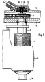
Der erfindungsgemäße Belagverschleißdetektor
sitzt in einem Gehäuse 11, das an einer Gehäuseabdeckung
bzw. einem Deckelteil 5b der Zuspannvorrichtung
lösbar befestigt ist. Wie insbesondere der Querschnittsansicht
der Fig.2 zu entnehmen ist, erfolgt die Befestigung
des Gehäuses 11 am Deckelteil 5b mittels einer
Schnappbefestigung, die aus mehreren, nach unten
weisenden Nasen 41 gebildet ist, die die Innenränder
einer geeignet geformten Bohrung des Deckelteils 5b
umgreifen. Um zu erreichen, daß ins Innere der Zuspannvorrichtung
kein Schmutz und keine Feuchtigkeit
eindringen kann, ist am Außenumfang des Gehäuses
11 eine ringförmige Dichtung 60 in Form eine O-Rings
oder eines Vierkant-Rings, der beispielsweise aus Silikon
oder Gummi besteht, angeordnet.The lining wear detector according to the invention
sits in a
Im Inneren des Gehäuses 11 ist ein Belagverschleißdetektor
in Form eines Drehpotentiometers 12
angeordnet. Das Drehpotentiometer 12 wird über ein
Untersetzungsgetriebe 13 angetrieben, das seinerseits
über eine Innenverzahnung 22 von einem Ritzel 21 angetrieben
wird. Das Ritzel 21 ist am hinteren Ende der
Nachstelleinrichtung 3 befestigt, so daß das Untersetzungsgetriebe
13 proportional zum Belagverschleiß angetrieben
wird. Um zu erreichen, daß das Ausgangssignal
des Drehpotentiometers 12 trotz mehrerer Umdrehungen
der Stellspindel 1 einen eindeutigen Wert darstellt,
ist der Untersetzungsfaktor des Untersetzungsgetriebes
13 so gewählt, daß die von der Nachstelleinrichtung
1 während des gesamten Nachstellzyklus' insgesamt
durchgeführten Umdrehungen auf höchstens eine
Umdrehung reduziert werden. Zur Erzielung einer möglichst
kompakten Bauweise handelt es sich bei dem Untersetzungsgetriebe
13 vorzugsweise um ein sogenanntes
Zykloidengetriebe. Im übrigen wird bezüglich
näherer Einzelheiten eines derartigen, mit einem Untersetzungsgetriebe
versehenen Drehpotentiometers auf
die nicht vorveröffentlichte DE-A-42 12 387 verwiesen.
auf deren Offenbarung voll inhaltlich Bezug genommen
wird. Wie aus dieser älteren Anmeldung hervorgeht,
empfiehlt es sich bei einer derartigen Getriebe/Potentiometer-Anordnung,
das Untersetzungsgetriebe in einer
(nicht näher gezeigten) Lagerungsvorrichtung zu lagern,
die derart aufgebaut ist, daß das Untersetzungsgetriebe
13 zwar drehfest, jedoch unter Aufrechterhallung
einer Längs- und Querschiebbarkeit getragen wird.
Hierdurch wird erreicht. daß nicht zu vermeidende
Schwenk- und Nickbewegungen der Nachstelleinrichtung
ohne Einfluß auf die erzielbare Meßgenauigkeit
kompensiert werden können.Inside the
Der erfindungsgemäße Belagverschleißdetektor
bzw. die in der Ausführungsform dargestellte Kombination
aus einem Untersetzungsgetriebe 13 und dem
Drehpotentiometer 12 sind im Gehäuse 11 befestigt und
bilden somit mit diesem eine integrale Baueinheit. Die
Befestigung im Gehäuse 11 erfolgt dabei mittels einer
Schnappvorrichtung, die durch mehrere, einander zugeordnete
Nasen 31 und 32 gebildet ist. Am Gehäuse
11 ist weiterhin eine Kabel zuführung 71 in Form eines
im wesentlichen rohrartigen, schräg nach oben verlaufenden
Ansatzes ausgebildet. Durch diese Kabelzuführung
erfolgt über mindestens eine Signalleitung 73 der
Signalabgriff am Drehpotentiometer 12, wobei über ein
entsprechendes Dichtelement 72 sichergestellt ist, daß
keine Feuchtigkeit oder Schmutz ins Innere gelangen
kann. Der Anschluß der Signalleitung(en) 73 am Drehpotentiometer
12 kann beispielsweise durch Löten erfolgen.The lining wear detector according to the invention
or the combination shown in the embodiment
from a
Wie insbesondere aus der Draufsicht der Fig.3 zu
erkennen ist, ist am Umfang des Gehäuses 11 eine Rasterverzahnung
52 vorgesehen, die mit einer nach unten
weisenden Nase 51 in Eingriff steht. Hierdurch ist
es möglich, die Montagerichtung des Gehäuses 11 in
bestimmten Winkelabständen festzulegen. Dies ermöglicht
es, die Signalleitung(en) 73 über die Kabelzuführung
71 so auszurichten, daß in Abhängigkeit von der
jeweiligen Einbaulage der Scheibenbremse ein optimaler
kabelverlauf gewährleistet ist.As can be seen in particular from the top view in FIG
can be seen is a raster toothing on the circumference of the
Zur Demontage des erfindungsgemäßen Belagverschleißdetektors
wird von Hand oder gegebenenfalls
unter Zuhilfenahme eines Schraubenziehers oder dergleichen
solange nach oben ein gewisser Druck ausgeübt,
bis die Nasen 41 außer Eingriff mit dem unteren
Rand 42 der Gehäusebohrung geraten: das Gehäuse
11 kann dann mitsamt der in seinem Inneren befindlichen
Drehpotentiometer/Getriebe-Anordnung nach
oben abgezogen werden, wobei das Ritzel 21 außer
Eingriff mit der Innenverzahnung 22 des Untersetzungsgetriebes
13 gerät. Das Montieren eines neuen oder generalüberholten
Detektors geschieht auf ebenso einfache
Weise in umgekehrter Reihenfolge.For dismantling the lining wear detector according to the invention
is done by hand or if necessary
with the help of a screwdriver or the like
as long as there is some pressure
until the lugs 41 disengage from the lower one
Edge 42 of the housing bore: the
Bezüglich weiterer, nicht näher erläuterter Vorteile und Wirkungen der Erfindung wird auf die Zeichnung verwiesenRegarding further, not explained advantages and effects of the invention will be on the drawing referred
Claims (13)
- Pad wear detector (10) for a disk brake, comprising an adjusting means (3, 6) which maintains the ventilation gap of the brake shoes substantially constant by means of at least one adjuster (1) acting in the axial direction and coupled to the pad wear detector (10) in such a way that the latter detects the relative axial position of said adjuster (1) and derives therefrom a corresponding wear signal, with the pad wear detector (10) being arranged in a separate housing (11) detachably secured to a lid element (5b) of the disk brake by means of a snap-on fastening means (41, 42) and being adapted for being actuated by said adjusting means (3, 6) via a releasable coupling component (21, 22),
characterised in that
said housing (11) is fastened for rotation on said lid element (5b) of the disk brake. - Pad wear detector according to Claim 1, characterised in that the pad wear detector (10) is fastened inside said housing (11) and co-operates therewith for forming an integral component.
- Pad wear detector according to Claim 2, characterised in that the pad wear detector (10) is fastened inside said housing (11) by means of a snap-on fastening means (31, 32).
- Pad wear detector according to Claim 1, characterised in that said housing (11) is rotatable through 360°.
- Pad wear detector according to Claim 1 or 4, characterised in that said housing (11) is rotatable in steps by means of a latching means, preferably in the form of a locking serration means (51, 52).
- Pad wear detector according to any of the Claims 1 to 5, characterised in that a sealing member (60) in the form of an O-ring, a square ring or the like is disposed between said housing (11) and its seat on the disk brake.
- Pad wear detector according to any of the Claims 1 to 7, characterised in that a cable duct (71) formed in said housing (11) comprises a seal (72) for the signal line(s) of the detector.
- Pad wear detector according to any of the Claims 1 to 7, characterised in that said housing (11) is made of a plastic material.
- Pad wear detector according to any of the Claims 1 to 8, characterised in that said adjusting means (3, 6) adjusts said adjuster(s) (1) by way of a rotating movement, with the pad wear detector (10) comprising a rotational drive for detecting the respective angle of rotation, and wherein said coupling component consists of a pinion (21) which engages in a corresponding internal toothing (22) of the pad wear detector (10).
- Pad wear detector according to Claim 9, characterised in that the pad wear detector (10) comprises a revolving potentiometer (12).
- Pad wear detector according to Claim 10, characterised in that a reduction gear (13), preferably in the form of a cycloid-type gearing, is disposed between said revolving potentiometer (12) and said coupling component (21, 22).
- Pad wear detector according to Claim 11, characterised in that said reduction gear (13) is supported in a bearing device which carries said reduction gear (13) so as to prevent it from rotation whilst displaceability in the longitudinal and transverse directions is maintained.
- Pad wear detector according to Claim 12, characterised in that said reduction gear (13) and its bearing device co-operate with said revolving potentiometer (12) so as to form an integral component, and are fastened inside said housing (11) together with said potentiometer.
Applications Claiming Priority (3)
| Application Number | Priority Date | Filing Date | Title |
|---|---|---|---|
| DE4230831A DE4230831B4 (en) | 1992-09-15 | 1992-09-15 | Pad wear detector for a disc brake |
| DE4230831 | 1992-09-15 | ||
| PCT/DE1993/000754 WO1994007050A1 (en) | 1992-09-15 | 1993-08-18 | Pad wear detector for a disc brake |
Publications (3)
| Publication Number | Publication Date |
|---|---|
| EP0659243A1 EP0659243A1 (en) | 1995-06-28 |
| EP0659243B1 EP0659243B1 (en) | 1996-06-12 |
| EP0659243B2 true EP0659243B2 (en) | 2000-02-09 |
Family
ID=6467998
Family Applications (1)
| Application Number | Title | Priority Date | Filing Date |
|---|---|---|---|
| EP93918897A Expired - Lifetime EP0659243B2 (en) | 1992-09-15 | 1993-08-18 | Pad wear detector for a disc brake |
Country Status (5)
| Country | Link |
|---|---|
| EP (1) | EP0659243B2 (en) |
| JP (1) | JPH08504251A (en) |
| BR (1) | BR9307052A (en) |
| DE (2) | DE4230831B4 (en) |
| WO (1) | WO1994007050A1 (en) |
Families Citing this family (12)
| Publication number | Priority date | Publication date | Assignee | Title |
|---|---|---|---|---|
| GB9320369D0 (en) * | 1993-10-02 | 1993-11-24 | Lucas Ind Plc | Brake wear sensor |
| GB9411477D0 (en) * | 1994-06-08 | 1994-07-27 | Lucas Ind Plc | Brake lining wear sensing system |
| JP3880626B2 (en) * | 1996-02-07 | 2007-02-14 | メリター・オートモーティヴ・インコーポレーテッド | Brake wear sensor |
| DE19907938B4 (en) * | 1999-02-24 | 2018-07-19 | Knorr-Bremse Systeme für Nutzfahrzeuge GmbH | Sealing element for two or more housing parts of a pneumatic disc brake device |
| AU2003206297A1 (en) | 2002-02-06 | 2003-09-02 | Haldex Brake Products Ab | Digital sensor |
| DE10233844B4 (en) * | 2002-07-25 | 2007-06-14 | Knorr-Bremse Systeme für Schienenfahrzeuge GmbH | Device and method for monitoring the functional and / or wear state of brake pads and brake discs of a vehicle brake |
| DE102006042777B3 (en) * | 2006-09-12 | 2007-10-18 | Knorr-Bremse Systeme für Nutzfahrzeuge GmbH | Disc brake for commercial vehicle has brake lining wear sensor and concentric wear sender coupled to brake adjustment spindle |
| EP2203659B1 (en) | 2007-09-24 | 2011-06-22 | KNORR-BREMSE Systeme für Nutzfahrzeuge GmbH | Disc brake, in particlar for a utility vehicle |
| DE202012001863U1 (en) | 2012-02-22 | 2012-03-19 | Haldex Brake Products Ab | Disc brake and sensor device for this |
| DE102012006088B4 (en) * | 2012-03-26 | 2017-11-16 | Knorr-Bremse Systeme für Nutzfahrzeuge GmbH | Sliding caliper disc brake of a motor vehicle |
| CH706551A2 (en) | 2012-05-23 | 2013-11-29 | Schwanden Kunststoff | Housing shell for a Verschleisssensor a vehicle brake system. |
| DE102012012830A1 (en) | 2012-06-28 | 2014-01-02 | Knorr-Bremse Systeme für Nutzfahrzeuge GmbH | Disc brake of a motor vehicle |
Citations (1)
| Publication number | Priority date | Publication date | Assignee | Title |
|---|---|---|---|---|
| DE3921294A1 (en) † | 1989-06-29 | 1991-01-10 | Hella Kg Hueck & Co | Brake lining wear sensor for saddle disc brake - has latching connections and folding bellows giving multiple stage or continuous indication |
Family Cites Families (7)
| Publication number | Priority date | Publication date | Assignee | Title |
|---|---|---|---|---|
| DE3716202C3 (en) * | 1987-05-14 | 2000-03-09 | Knorr Bremse Systeme | Disc brake for vehicles |
| DE4017953A1 (en) * | 1990-06-05 | 1991-12-12 | Wabco Westinghouse Fahrzeug | BRAKE ACTUATING DEVICE WITH A DEVICE FOR REALIZING A BRAKE |
| DE4032885A1 (en) * | 1990-10-17 | 1992-04-23 | Knorr Bremse Ag | DISC BRAKE FOR VEHICLES, IN PARTICULAR ROAD VEHICLES |
| SE468136B (en) * | 1990-11-28 | 1992-11-09 | Volvo Ab | DEVICE FOR INDICATING BRAKE COATING |
| DE4041318A1 (en) * | 1990-12-21 | 1992-06-25 | Knorr Bremse Ag | PAD WEAR INDICATOR DEVICE FOR PRESSURE MEDIUM, PREFERABLY PNEUMATICALLY OPERABLE DISC BRAKES OF COMMERCIAL VEHICLES |
| DE4212387B4 (en) * | 1992-04-13 | 2004-08-26 | Knorr-Bremse Ag | Pad wear detector for a compressed air operated disc brake |
| DE4212407A1 (en) * | 1992-04-13 | 1993-10-14 | Knorr Bremse Gmbh | Air gap detector for a compressed air operated disc brake |
-
1992
- 1992-09-15 DE DE4230831A patent/DE4230831B4/en not_active Expired - Fee Related
-
1993
- 1993-08-18 BR BR9307052A patent/BR9307052A/en unknown
- 1993-08-18 WO PCT/DE1993/000754 patent/WO1994007050A1/en active IP Right Grant
- 1993-08-18 EP EP93918897A patent/EP0659243B2/en not_active Expired - Lifetime
- 1993-08-18 JP JP6507646A patent/JPH08504251A/en active Pending
- 1993-08-18 DE DE59302942T patent/DE59302942D1/en not_active Expired - Fee Related
Patent Citations (1)
| Publication number | Priority date | Publication date | Assignee | Title |
|---|---|---|---|---|
| DE3921294A1 (en) † | 1989-06-29 | 1991-01-10 | Hella Kg Hueck & Co | Brake lining wear sensor for saddle disc brake - has latching connections and folding bellows giving multiple stage or continuous indication |
Also Published As
| Publication number | Publication date |
|---|---|
| EP0659243B1 (en) | 1996-06-12 |
| JPH08504251A (en) | 1996-05-07 |
| EP0659243A1 (en) | 1995-06-28 |
| DE4230831B4 (en) | 2004-02-26 |
| DE4230831A1 (en) | 1994-03-17 |
| DE59302942D1 (en) | 1996-07-18 |
| WO1994007050A1 (en) | 1994-03-31 |
| BR9307052A (en) | 1999-06-29 |
Similar Documents
| Publication | Publication Date | Title |
|---|---|---|
| DE102006042777B3 (en) | Disc brake for commercial vehicle has brake lining wear sensor and concentric wear sender coupled to brake adjustment spindle | |
| EP3071861B1 (en) | Sensor device and disc brake comprising a sensor device | |
| EP0566006B1 (en) | Lining wear detector for an air operated disc brake | |
| EP0544851B1 (en) | Pressure-controlled adjusting device for a vehicle brake | |
| EP0659243B2 (en) | Pad wear detector for a disc brake | |
| DE4239947C1 (en) | DRIVE UNIT FOR CONTROLLING AND CONTROLLING FITTINGS OR THE LIKE | |
| EP2203659A1 (en) | Disc brake, in particlar for a utility vehicle | |
| DE19600819A1 (en) | Wear monitoring device | |
| WO2004071244A3 (en) | Electromotive linear drive unit | |
| EP0271864A2 (en) | Actuating mechanism with an automatic adjustment for brakes, especially for juggernauts | |
| DE2402469B2 (en) | Automatic readjusting device for a mechanically actuated partially-lined disc brake, in particular a floating-caliper disc brake | |
| DE202012001863U1 (en) | Disc brake and sensor device for this | |
| EP2766628B1 (en) | Disk brake for a utility vehicle | |
| DE4243875C2 (en) | Device for detecting the wear of a lining in a disc brake | |
| EP0565997B1 (en) | Air pressure operated disc brake | |
| EP0545358A1 (en) | Actuating mechanism with an automatic adjustment for brakes, especially in trucks and omnibuses | |
| WO1993021458A1 (en) | Clearance detector for a pneumatically operated disc brake | |
| DE102005053303B4 (en) | Device for displaying the state of wear of vehicle brakes | |
| DE102015114440B4 (en) | Disc brake with synchronization unit | |
| DE102012007019A1 (en) | Disk brake for commercial vehicle, has housing formed as multipart and comprising housing lower part connected with brake caliper and housing upper part attached to housing lower part, and liner wear sensor arranged in housing upper part | |
| EP0636220B1 (en) | Pneumatically operated disc brake | |
| EP2546541B1 (en) | Composants d'un frein à disque | |
| DE102006005297B3 (en) | Disc brake, in particular for commercial vehicles | |
| DE60005496T2 (en) | DIFFERENTIAL LOCK | |
| EP1606527B1 (en) | Actuating unit for an electromechanical disc brake |
Legal Events
| Date | Code | Title | Description |
|---|---|---|---|
| PUAI | Public reference made under article 153(3) epc to a published international application that has entered the european phase |
Free format text: ORIGINAL CODE: 0009012 |
|
| 17P | Request for examination filed |
Effective date: 19950307 |
|
| AK | Designated contracting states |
Kind code of ref document: A1 Designated state(s): DE FR GB IT SE |
|
| 17Q | First examination report despatched |
Effective date: 19951031 |
|
| GRAH | Despatch of communication of intention to grant a patent |
Free format text: ORIGINAL CODE: EPIDOS IGRA |
|
| GRAA | (expected) grant |
Free format text: ORIGINAL CODE: 0009210 |
|
| AK | Designated contracting states |
Kind code of ref document: B1 Designated state(s): DE FR GB IT SE |
|
| PG25 | Lapsed in a contracting state [announced via postgrant information from national office to epo] |
Ref country code: IT Free format text: LAPSE BECAUSE OF FAILURE TO SUBMIT A TRANSLATION OF THE DESCRIPTION OR TO PAY THE FEE WITHIN THE PRE;WARNING: LAPSES OF ITALIAN PATENTS WITH EFFECTIVE DATE BEFORE 2007 MAY HAVE OCCURRED AT ANY TIME BEFORE 2007. THE CORRECT EFFECTIVE DATE MAY BE DIFFERENT FROM THE ONE RECORDED.SCRIBED TIME-LIMIT Effective date: 19960612 Ref country code: GB Effective date: 19960612 Ref country code: FR Effective date: 19960612 |
|
| REF | Corresponds to: |
Ref document number: 59302942 Country of ref document: DE Date of ref document: 19960718 |
|
| GRAH | Despatch of communication of intention to grant a patent |
Free format text: ORIGINAL CODE: EPIDOS IGRA |
|
| PG25 | Lapsed in a contracting state [announced via postgrant information from national office to epo] |
Ref country code: SE Effective date: 19960912 |
|
| EN | Fr: translation not filed | ||
| GBV | Gb: ep patent (uk) treated as always having been void in accordance with gb section 77(7)/1977 [no translation filed] |
Effective date: 19960612 |
|
| PLBQ | Unpublished change to opponent data |
Free format text: ORIGINAL CODE: EPIDOS OPPO |
|
| PLBI | Opposition filed |
Free format text: ORIGINAL CODE: 0009260 |
|
| PLBF | Reply of patent proprietor to notice(s) of opposition |
Free format text: ORIGINAL CODE: EPIDOS OBSO |
|
| 26 | Opposition filed |
Opponent name: LUCAS INDUSTRIES PUBLIC LIMITED COMPANY Effective date: 19970312 |
|
| PLBF | Reply of patent proprietor to notice(s) of opposition |
Free format text: ORIGINAL CODE: EPIDOS OBSO |
|
| PLBF | Reply of patent proprietor to notice(s) of opposition |
Free format text: ORIGINAL CODE: EPIDOS OBSO |
|
| PLAW | Interlocutory decision in opposition |
Free format text: ORIGINAL CODE: EPIDOS IDOP |
|
| PLAW | Interlocutory decision in opposition |
Free format text: ORIGINAL CODE: EPIDOS IDOP |
|
| PUAH | Patent maintained in amended form |
Free format text: ORIGINAL CODE: 0009272 |
|
| STAA | Information on the status of an ep patent application or granted ep patent |
Free format text: STATUS: PATENT MAINTAINED AS AMENDED |
|
| 27A | Patent maintained in amended form |
Effective date: 20000209 |
|
| AK | Designated contracting states |
Kind code of ref document: B2 Designated state(s): DE FR GB IT SE |
|
| PGFP | Annual fee paid to national office [announced via postgrant information from national office to epo] |
Ref country code: DE Payment date: 20080829 Year of fee payment: 16 |
|
| PG25 | Lapsed in a contracting state [announced via postgrant information from national office to epo] |
Ref country code: DE Free format text: LAPSE BECAUSE OF NON-PAYMENT OF DUE FEES Effective date: 20100302 |