EP3071861B1 - Sensor device and disc brake comprising a sensor device - Google Patents
Sensor device and disc brake comprising a sensor device Download PDFInfo
- Publication number
- EP3071861B1 EP3071861B1 EP14802835.0A EP14802835A EP3071861B1 EP 3071861 B1 EP3071861 B1 EP 3071861B1 EP 14802835 A EP14802835 A EP 14802835A EP 3071861 B1 EP3071861 B1 EP 3071861B1
- Authority
- EP
- European Patent Office
- Prior art keywords
- sensor
- sensor device
- variable
- brake
- gear
- Prior art date
- Legal status (The legal status is an assumption and is not a legal conclusion. Google has not performed a legal analysis and makes no representation as to the accuracy of the status listed.)
- Active
Links
- 230000007246 mechanism Effects 0.000 claims description 8
- 230000007480 spreading Effects 0.000 claims description 7
- 230000005540 biological transmission Effects 0.000 description 18
- 230000008878 coupling Effects 0.000 description 16
- 238000010168 coupling process Methods 0.000 description 16
- 238000005859 coupling reaction Methods 0.000 description 16
- 230000000903 blocking effect Effects 0.000 description 5
- 238000001514 detection method Methods 0.000 description 5
- 210000001331 nose Anatomy 0.000 description 5
- 230000002441 reversible effect Effects 0.000 description 5
- 238000013519 translation Methods 0.000 description 5
- 230000008859 change Effects 0.000 description 3
- 238000013461 design Methods 0.000 description 3
- 230000001360 synchronised effect Effects 0.000 description 3
- 230000004323 axial length Effects 0.000 description 2
- 238000006243 chemical reaction Methods 0.000 description 2
- 238000010276 construction Methods 0.000 description 2
- 230000000694 effects Effects 0.000 description 2
- 230000001939 inductive effect Effects 0.000 description 2
- 238000009434 installation Methods 0.000 description 2
- 230000002427 irreversible effect Effects 0.000 description 2
- 239000000463 material Substances 0.000 description 2
- 230000003287 optical effect Effects 0.000 description 2
- 238000012546 transfer Methods 0.000 description 2
- 230000006978 adaptation Effects 0.000 description 1
- 230000015572 biosynthetic process Effects 0.000 description 1
- 230000008094 contradictory effect Effects 0.000 description 1
- 238000011156 evaluation Methods 0.000 description 1
- 230000006870 function Effects 0.000 description 1
- 230000008571 general function Effects 0.000 description 1
- 230000000670 limiting effect Effects 0.000 description 1
- 238000005259 measurement Methods 0.000 description 1
- 239000002184 metal Substances 0.000 description 1
- 238000000034 method Methods 0.000 description 1
- 230000036961 partial effect Effects 0.000 description 1
- 238000003825 pressing Methods 0.000 description 1
- 230000008569 process Effects 0.000 description 1
- 238000012545 processing Methods 0.000 description 1
- 238000003908 quality control method Methods 0.000 description 1
- 230000002829 reductive effect Effects 0.000 description 1
- 238000007789 sealing Methods 0.000 description 1
- 230000035945 sensitivity Effects 0.000 description 1
Images


Classifications
-
- F—MECHANICAL ENGINEERING; LIGHTING; HEATING; WEAPONS; BLASTING
- F16—ENGINEERING ELEMENTS AND UNITS; GENERAL MEASURES FOR PRODUCING AND MAINTAINING EFFECTIVE FUNCTIONING OF MACHINES OR INSTALLATIONS; THERMAL INSULATION IN GENERAL
- F16D—COUPLINGS FOR TRANSMITTING ROTATION; CLUTCHES; BRAKES
- F16D65/00—Parts or details
- F16D65/38—Slack adjusters
- F16D65/40—Slack adjusters mechanical
- F16D65/52—Slack adjusters mechanical self-acting in one direction for adjusting excessive play
- F16D65/56—Slack adjusters mechanical self-acting in one direction for adjusting excessive play with screw-thread and nut
- F16D65/567—Slack adjusters mechanical self-acting in one direction for adjusting excessive play with screw-thread and nut for mounting on a disc brake
- F16D65/568—Slack adjusters mechanical self-acting in one direction for adjusting excessive play with screw-thread and nut for mounting on a disc brake for synchronous adjustment of actuators arranged in parallel
-
- F—MECHANICAL ENGINEERING; LIGHTING; HEATING; WEAPONS; BLASTING
- F16—ENGINEERING ELEMENTS AND UNITS; GENERAL MEASURES FOR PRODUCING AND MAINTAINING EFFECTIVE FUNCTIONING OF MACHINES OR INSTALLATIONS; THERMAL INSULATION IN GENERAL
- F16D—COUPLINGS FOR TRANSMITTING ROTATION; CLUTCHES; BRAKES
- F16D55/00—Brakes with substantially-radial braking surfaces pressed together in axial direction, e.g. disc brakes
- F16D55/02—Brakes with substantially-radial braking surfaces pressed together in axial direction, e.g. disc brakes with axially-movable discs or pads pressed against axially-located rotating members
- F16D55/22—Brakes with substantially-radial braking surfaces pressed together in axial direction, e.g. disc brakes with axially-movable discs or pads pressed against axially-located rotating members by clamping an axially-located rotating disc between movable braking members, e.g. movable brake discs or brake pads
- F16D55/224—Brakes with substantially-radial braking surfaces pressed together in axial direction, e.g. disc brakes with axially-movable discs or pads pressed against axially-located rotating members by clamping an axially-located rotating disc between movable braking members, e.g. movable brake discs or brake pads with a common actuating member for the braking members
- F16D55/225—Brakes with substantially-radial braking surfaces pressed together in axial direction, e.g. disc brakes with axially-movable discs or pads pressed against axially-located rotating members by clamping an axially-located rotating disc between movable braking members, e.g. movable brake discs or brake pads with a common actuating member for the braking members the braking members being brake pads
- F16D55/2255—Brakes with substantially-radial braking surfaces pressed together in axial direction, e.g. disc brakes with axially-movable discs or pads pressed against axially-located rotating members by clamping an axially-located rotating disc between movable braking members, e.g. movable brake discs or brake pads with a common actuating member for the braking members the braking members being brake pads in which the common actuating member is pivoted
-
- F—MECHANICAL ENGINEERING; LIGHTING; HEATING; WEAPONS; BLASTING
- F16—ENGINEERING ELEMENTS AND UNITS; GENERAL MEASURES FOR PRODUCING AND MAINTAINING EFFECTIVE FUNCTIONING OF MACHINES OR INSTALLATIONS; THERMAL INSULATION IN GENERAL
- F16D—COUPLINGS FOR TRANSMITTING ROTATION; CLUTCHES; BRAKES
- F16D66/00—Arrangements for monitoring working conditions, e.g. wear, temperature
- F16D66/02—Apparatus for indicating wear
- F16D66/021—Apparatus for indicating wear using electrical detection or indication means
- F16D66/026—Apparatus for indicating wear using electrical detection or indication means indicating different degrees of lining wear
-
- F—MECHANICAL ENGINEERING; LIGHTING; HEATING; WEAPONS; BLASTING
- F16—ENGINEERING ELEMENTS AND UNITS; GENERAL MEASURES FOR PRODUCING AND MAINTAINING EFFECTIVE FUNCTIONING OF MACHINES OR INSTALLATIONS; THERMAL INSULATION IN GENERAL
- F16D—COUPLINGS FOR TRANSMITTING ROTATION; CLUTCHES; BRAKES
- F16D66/00—Arrangements for monitoring working conditions, e.g. wear, temperature
- F16D2066/003—Position, angle or speed
-
- F—MECHANICAL ENGINEERING; LIGHTING; HEATING; WEAPONS; BLASTING
- F16—ENGINEERING ELEMENTS AND UNITS; GENERAL MEASURES FOR PRODUCING AND MAINTAINING EFFECTIVE FUNCTIONING OF MACHINES OR INSTALLATIONS; THERMAL INSULATION IN GENERAL
- F16D—COUPLINGS FOR TRANSMITTING ROTATION; CLUTCHES; BRAKES
- F16D55/00—Brakes with substantially-radial braking surfaces pressed together in axial direction, e.g. disc brakes
- F16D55/02—Brakes with substantially-radial braking surfaces pressed together in axial direction, e.g. disc brakes with axially-movable discs or pads pressed against axially-located rotating members
- F16D55/22—Brakes with substantially-radial braking surfaces pressed together in axial direction, e.g. disc brakes with axially-movable discs or pads pressed against axially-located rotating members by clamping an axially-located rotating disc between movable braking members, e.g. movable brake discs or brake pads
- F16D55/224—Brakes with substantially-radial braking surfaces pressed together in axial direction, e.g. disc brakes with axially-movable discs or pads pressed against axially-located rotating members by clamping an axially-located rotating disc between movable braking members, e.g. movable brake discs or brake pads with a common actuating member for the braking members
- F16D55/225—Brakes with substantially-radial braking surfaces pressed together in axial direction, e.g. disc brakes with axially-movable discs or pads pressed against axially-located rotating members by clamping an axially-located rotating disc between movable braking members, e.g. movable brake discs or brake pads with a common actuating member for the braking members the braking members being brake pads
-
- F—MECHANICAL ENGINEERING; LIGHTING; HEATING; WEAPONS; BLASTING
- F16—ENGINEERING ELEMENTS AND UNITS; GENERAL MEASURES FOR PRODUCING AND MAINTAINING EFFECTIVE FUNCTIONING OF MACHINES OR INSTALLATIONS; THERMAL INSULATION IN GENERAL
- F16D—COUPLINGS FOR TRANSMITTING ROTATION; CLUTCHES; BRAKES
- F16D66/00—Arrangements for monitoring working conditions, e.g. wear, temperature
- F16D66/02—Apparatus for indicating wear
Definitions
- the invention relates to a sensor device for a disc brake, in particular for a motor vehicle, according to the preamble of claim 1.
- the invention also relates to a disc brake with such a sensor device.
- Such sensor devices are used for detecting a state of wear of brake pads and brake disc of a disc brake.
- sensor devices are also used to make a detection of an operating stroke of a brake disk application device in order to determine a current clearance.
- Such disc brakes are usually pneumatically actuated and equipped with automatic mechanical wear adjusters. These wear adjusting devices have a very reliable effect and reduce the clearance that has become too large. They are known in different designs, such as e.g. mechanical adjuster with automatic adjustment of a friction point. At each braking operation, the adjusting device, e.g. by a feed element of a brake disk application device, activated. In case of wear of brake pads and brake disc, an automatic readjustment of the pads by means of the wear adjusting device, e.g. by an adjusting movement of variable-length threaded pipes.
- an adjuster describes the document DE 10 2004 037 771 A1 ,
- a drive rotational movement for example, from a torque limiting device, for example, with a ball ramp, forwarded via a continuously acting clutch (slip clutch) to an adjusting spindle of a threaded pipe.
- a continuously acting clutch slip clutch
- the adjusting element eg an adjusting spindle
- An example of this is illustrated in the document EP 1 892 435 B1 , It is considered disadvantageous that the actuating stroke is significantly smaller than the wear path.
- Numerical examples are included a usual brake, for example, an operating stroke of about 4.5 mm and an adjustment of about 60 mm.
- a currently common interface of brake to a vehicle control system is an analog transmission in which an electrical voltage with respect to a common ground corresponds to the measured value. Since the adjustment path determines the amplitude of the transmission signal, this signal amplitude will be due to the Betuschistshubs in the same ratio as a maximum operating stroke to a maximum wear path. For this purpose, a numerical example of the above-mentioned conventional brake will be given.
- the voltage amplitude is 2.5 V.
- the actuation stroke can be determined at most to an accuracy of 0.48 mm.
- a clearance is usually in the order of 0.5 ... 1.2 mm and is thus very difficult to determine.
- the DE 102010032515 A1 describes a brake wear sensor of a disc brake.
- a superposition of Nachstellweg and Betchanistshub is realized by means of a planetary gear.
- the adjustment is initiated as a rotational movement on the sun gear of the planetary gear.
- the actuating stroke is introduced as a further rotational movement via the planet carrier of the planetary gear.
- the rotation of the ring gear of the planetary gear is detected with a suitable encoder, such as a Hall sensor, a potentiometer, an inductive, optical or acoustic encoder element.
- the object of the present invention is to provide an improved sensor device. Another object is to provide an improved disc brake.
- a sensor device which can be changed in its construction by a small number of parts for different tasks in a simple manner. Thereby, e.g. a storage quantity can be reduced and changed just before use for various purposes quickly and easily.
- a sensor device for a disc brake has a sensor gear which can be coupled to at least one sensor, wherein the sensor gear is arranged in a housing as a planetary gear and has an input for a first variable to be detected by the sensor device, which is assigned to a wear of the disc brake, and an input for a second size to be detected by the sensor device, which is assigned to an actuating stroke of the disc brake.
- the sensor device is of a first state for detecting the first size, which is associated with a wear of the disc brake, and the second size, which is associated with an actuating stroke of the disc brake, in a second state for detecting only the first size, the wear of the Disc brake is assigned, convertible.
- a disc brake according to the invention in particular for a motor vehicle, with a clamping device with a spreading mechanism, preferably with a brake rotary lever, a wear adjusting device, which has at least one mechanical adjusting device which is preferably used in a spindle unit of the disc brake and with the spreading mechanism, preferably with the brake rotary lever coupled is, is equipped with a sensor device according to the invention.
- the input of the sensor operation of the sensor device for the first variable to be detected is coupled to the at least one mechanical adjustment device, and the input of the sensor operation of the sensor device for the second variable to be detected is coupled to the expansion mechanism, preferably to the brake rotation lever, via a stroke sensor drive.
- the sensor gear is equipped with an interface for coupling a transmitter.
- This can e.g. be a non-rotatable connector.
- the spreading mechanism preferably the brake rotary lever, drives two drives, namely, on the one hand, the adjusting device and, on the other, the stroke sensor drive.
- the input of the sensor operation for the first variable to be detected is a sun gear of the sensor operation
- an input for the second variable to be detected is a planet carrier of the sensor gear with a planet carrier toothing.
- the planetary gear serves as a single sensor gear for superimposing both input variables and can be used without own changes.
- the input for the second variable to be detected is in the first state of the sensor device with a stroke sensor drive unit Intervention and in the second state of the sensor device, it is blocked.
- the Hubsensorantriebsaku at least one gear, which is in the first state of the sensor device with the planet carrier toothing, which is an external toothing, in an opening of the housing in engagement.
- the at least one gear transmission with a certain translation is possible, whereby the subsequent rotation of the ring gear due to the Betreliistshubs to that rotation of the ring gear as a result of the adjustment, i. is tunable through the first input.
- the transmission can be done with little play, wherein the actuating stroke is detected with a high accuracy and a high resolution in contrast to the prior art.
- the pivoting of the brake rotary lever e.g. designed as eccentric lever, used to initiate the operating stroke as a pivoting / twisting movement in the planetary gear.
- the problem that the pivot axes of brake lever and adjusting spindle or sensor axis of the sensor device are not in a plane and have an axial offset is solved by the gear, wherein the axial offset is compensated in a simple manner. This is advantageous because this axial offset is a consequence of the design of the brake rotary lever as an eccentric lever and can not be compensated for reasons of space.
- the at least one gear is rotatably mounted in a holder and the housing and axially limited. This allows a simple completion and installation of the gear.
- the gear can be installed quickly.
- the input for the second variable to be detected in the second state of the sensor device is rotationally blocked by at least one fixing tooth of a rotationally fixed to the housing holder, wherein the at least one fixing tooth with the planet carrier toothing, which is an external toothing, in an opening of the housing is engaged.
- the input of the sensor operation for the first variable to be detected is a drive shaft having at least one gear stage which is coupled to a sun gear of the sensor operation, and an input for the second variable to be detected is a planet carrier of the sensor gear with a planet carrier toothing.
- the above axial offset is compensated here by the distance from the drive shaft and sun gear.
- the sensor gear can maintain its space requirement.
- the input for the second variable to be detected in the first state of the sensor device is in engagement with a stroke sensor drive unit or is provided for direct engagement of a stroke sensor actuator of a disc brake to be assigned and blocked in the second state of the sensor device. Since the lever pivot axis and the axis of the input, i. of the planet carrier lie in one plane, the Hubsensorbetuschiger can be directly in engagement with the planet carrier. Of course, one or more gear stages can be interposed.
- the input for the second variable to be detected in the second state of the sensor device is rotationally blocked by at least one fixing arm, wherein the at least one fixing arm is in engagement with the planet carrier toothing, which is an outer toothing.
- the at least one fixing arm can be removably fastened to the housing again. This makes a reversible conversion possible. An irreversible change is of course also possible if the at least one fixing arm is detachably connected to the housing via a predetermined breaking section.
- the at least one fixing arm in the form of an insert in the housing is used rotationally fixed and removable again, as a simple and fast reversible changeover is possible.
- the above sensor device has at least one encoder, which is coupled to the sensor gear.
- the sensor device can be designed as a preassembled unit already together with an encoder.
- a disc brake is formed with at least two spindle units, wherein the at least one mechanical adjusting device is coupled to a driver via a synchronizing unit.
- the input of the sensor operation of the sensor device for the first variable to be detected is coupled to a driver shaft of the driver. This allows an effective space utilization.
- the stroke sensor drive Due to the orthogonal arrangement of the lever pivot axis and the axis of rotation of the adjusting spindle, the stroke sensor drive has an angle gear.
- An angular gear is, with a few exceptions, much more sensitive to tolerances than a spur gear.
- the axial offset between a plane of a lever pivot axis of the brake rotary lever and a plane of a sensor axis of the sensor device is compensated by at least one gear stage of the stroke sensor drive unit. So a bevel gear, even with a crown gear, possible.
- the crown gear is relatively insensitive to position tolerances. It is of course also e.g. a Hypoidgetriebe possible, with a sensitivity to positional tolerances is increased and a quality control could be more complex.
- the sensor device is arranged in the disc brake such that an axial offset between a plane of a lever pivot axis of the brake rotary lever, in which a sensor axis of the sensor device is located, and a plane of an axis of a spindle unit by at least one gear stage of a drive shaft, which is an input of Sensor operation of the sensor device for the first size to be detected is compensated.
- the Hubsensorbet2011iger example. with a crown gear directly with the planet carrier, or with the ring gear cooperate.
- the disc brake can also be operated by compressed air.
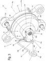
- Fig. 1 is a schematic perspective view of an embodiment of a disc brake 1 according to the invention with a sensor device according to the invention 15 and a wear adjustment device 10 is shown.
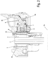
- Fig. 2 shows a schematic sectional view of the embodiment along the line II-II after Fig. 1 ,
- the disc brake 1 is shown in an embodiment as a two-stamp brake with a brake caliper 4, which engages over a brake disc 2.
- the brake disk 2 is rotatable about a brake disk axis 2a, wherein on both sides of the brake disk 2 in each case a brake pad 3 is arranged on a brake pad carrier 3a.
- the disc brake 1 is formed with a brake application device, which is designed here with a brake rotary lever 9, for tensioning the disc brake 1.
- the brake rotary lever 9 is also referred to as a spreading mechanism, is part of the application device, is pivotable about a lever pivot axis 9a and has a lever arm 9b, which e.g. can be actuated by a compressed air brake cylinder.
- the brake rotary lever 9 is pivotably mounted here about an unspecified bearing roller on the brake caliper 4 about the lever pivot axis 9a.
- a bridge 7 is in contact with the brake rotary lever 9 and can be actuated by the brake lever 2 when applying and releasing the brake in the direction of the brake disk axis 2 a back and forth.
- the bridge 7 is at its ends in each case with a spindle unit 5, 5 'via a respective threaded pipe 6, 6' coupled.
- Each spindle unit 5, 5 ' has an axis 5a, 5'a, the axis 5a of the spindle unit 5 being referred to as the adjuster axis 5a and the axis 5'a of the spindle unit 5' being referred to as the entrainment axis 5'a.
- the Nachstellerachse 5a and the driving axle 5'a are parallel and perpendicular to the brake disc axis 2a.
- the lever pivot axis 9a is parallel to the brake disk axis 2a and perpendicular to the Nachstellerachse 5a and the driving axle 5'a.
- the pressure pieces 6, 6 'a are in contact with a brake pad carrier 3 a of a brake application side 3, which is arranged on one side of the brake disk 2 of the disk brake 1.
- a further brake pad 3 with brake lining carrier 3a in the caliper 4 is fixed.
- This brake pad 3 is also called reaction-side brake pad 3.
- the caliper 4 may for example be a sliding caliper.
- a distance between a brake pad 3 and the brake disc 2 is referred to as a clearance.
- the clearance is first bridged when the disc brake 1 is actuated by the brake pad 3 being displaced by the bridge 7 operated by the brake lever 9 against the brake disc 2 of the disc brake 1. Due to the wear of the brake pads 3 and the brake disc 2, the clearance is increased.
- the term "friction point” is the point in which the brake pad 3 rests against the brake disc 2 of the disc brake 1. The friction point is reached when tightening after bridging the clearance. Further tightening then causes by pressing the brake pad 3 to the brake disc 2 braking. This of course also applies to the reaction-side brake pad 3. A release of the application device causes a reversal of the above-described process.
- the disc brake 1 comprises in the in Fig. 1
- a wear adjusting device 10 which serves to adjust the brake pad 3 / the brake pads 3 when worn, to restore the original clearance.
- the wear adjusting device 10 comprises an adjusting device 11 with a Nachstellerwelle 11 a, a driver 12 with a driving shaft 12 a and a synchronizing unit 13 for coupling of adjusting device 11 and driver 12th
- the adjusting device 11 is not explained here in detail, it can, for example, as in DE 10 2004 037 771 A1 be described and is used in the spindle unit 5 in the associated threaded tube 6 and coupled thereto.
- a longitudinal axis of the Nachstellerwelle 11a forms the Nachstellerachse 5a.
- the adjusting device 11 is coupled to the driver 12 such that a rotation of the Nachstellerwelle 11a and thus rotatably connected threaded tube 6 synchronously on the driver shaft 12a and thus on the rotatably connected to the driver shaft 12a threaded pipe 6 'is transmitted.
- the synchronizing unit 13 is shown only schematically, the Nachstellerwelle 11a with a synchronous wheel 13a, here a sprocket, the synchronizing unit 13 is rotatably connected.
- the synchronizing wheel 13a is connected via a synchronizing means 13b, here a chain, with a further synchronizing wheel 13'a, which is directly or indirectly non-rotatably coupled to the driving shaft 12a.
- This embodiment of the synchronizing unit 13 can only be seen as an example, other couplings, e.g. the threaded pipes 6, 6 'with each other, of course, are also possible.
- the adjusting device 11 is driven. This is done via a readjuster drive 14, which comprises a fixedly connected to the brake rotary lever 9 actuator 14a and a coupled to the adjusting device 11 Vietnamesestellerantriebselement 14b.
- the actuator 14a and the adjuster drive member 14b are engaged with each other.
- the actuator 14a may be formed as a pin, for example.
- the Nachstellerantriebselement 14b may be provided for example with a shift fork, which cooperates with the actuator 14a.
- the disc brake 1 is equipped with a sensor device 15.
- the sensor device 15 In a first state, the sensor device 15 for detecting a first size, namely the wear of the brake pads 3 including the brake disc 2, and for detecting a second size, namely an operating stroke of the application device is formed.
- the sensor device 15 can be switched from this first state to a second state.
- the sensor device 15 In the second state, the sensor device 15 detects only one size, namely the first size, the wear.
- the convertibility of the sensor device 15 will be described in detail below.
- the sensor device 15 with a donor, not shown, for example, a Hall sensor, a potentiometer, an inductive, and / or optical and / or acoustic encoder element is formed.
- the encoder not shown, is connected via a sensor connection line 15b to an evaluation unit, for example in a brake control unit.
- a sensor axis 15a of the sensor device 15 is arranged so that the driver axis 5'a coincides with the sensor axis 15a.
- the sensor device 15 is in this case arranged coaxially with the spindle unit 5 'and attached to the brake caliper 4 from the application side and fastened thereto, which will be described below (see Fig. 3-5 ). Furthermore, the sensor device 15 is coupled to the driver shaft 12a. Since the readjustment movement of the adjuster shaft 11a is transmitted to the driver shaft 12a by means of the synchronizer unit 13, here the adjuster movement of the driver shaft 12a can be used to detect the wear. The coupling with the driver shaft 12a with the sensor device 15 can take place in various ways. This will be further described below.
- the sensor device 15 is configured in this embodiment such that it can also detect the second variable, namely an actuating stroke of the application device of the disc brake 1, which here is the movement of the brake rotary lever 9.
- the second variable namely an actuating stroke of the application device of the disc brake 1, which here is the movement of the brake rotary lever 9.
- These detected two variables are transmitted by means of a sensor gear 16, which is formed for example as a superposition gear and has two inputs, superimposed on the encoder of the sensor device 15 transmitted.
- a sensor gear 16 which is formed for example as a superposition gear and has two inputs, superimposed on the encoder of the sensor device 15 transmitted.
- the actuating stroke is a linear movement (apart from the pivotal movement of the bridge 7) and is converted here into a pivoting movement for detection as a second variable for the sensor device 15. This is done by means of a Hubsensorantriebs 17, via which the sensor device 15 is coupled to the brake rotary lever 9.
- the stroke sensor drive 17 comprises a stroke sensor actuator 18 connected to the brake rotary lever 9 and a stroke sensor drive unit 19 coupled to the sensor device 15.
- FIG. 3 a schematic perspective view of a first embodiment of the sensor device according to the invention 15.
- Fig. 4 is a schematic, perspective sectional view of the first embodiment according to Fig. 3 shown.
- Fig. 5 shows a further schematic sectional view of the first embodiment according to Fig. 3 ,
- FIGS. 3 to 5 the Hubsensorantrieb 17 is shown with the Hubsensorbet2011iger 18 and the Hubsensorantriebstechnik 19 together with the sensor device 15 in different views and sections.
- Fig. 4 one to the lever pivot axis 9a vertical section through the coincident with the driver axis 5'a sensor axis 15a.
- the sectional view of Fig. 5 is a parallel to the plane coincident with the driving axis 5'a sensor axis 15a in the plane of the lever pivot axis 9a.
- the sensor device 15 with its sensor axis 15a has a housing 21 which accommodates both the encoder and the sensor gear 16.
- the senor device 15 can be executed either with a donor or without a donor.
- the encoder can also be retrofitted.
- the housing 21 in this example comprises a housing flange 21a and two gear receivers 21b and 21c.
- the housing flange 21a has at its periphery a kind of radially projecting eyes for attachment to the caliper 4 (see Fig. 1 ), in which case fastening elements 21e, eg screws, are used for fastening.
- the housing flange 21a is provided with unspecified rectangular retaining tabs, which are provided for fixing a lid with the donor, also not shown. These retaining tabs can, for example, cooperate with corresponding retaining lugs of this cover like a clip.
- the transmission receptacle 21b is cylindrical and has a wall which projects to the side toward the brake disk 2 and is partially closed on the brake disk side by a ring plate.
- the wall of the first gear housing 21b has an outer diameter which is smaller than an outer diameter of a shoulder which is arranged in the connection between the first gear housing 21b and the housing flange 21a.
- a seal 22 for example, an O-ring, applied, which is provided for sealing the housing 21 of the sensor device 15 relative to the caliper 4.
- the annular plate of the first transmission mount 21b has a bore.
- the edge of this bore is connected to a wall of the second gear housing 21c, which partially cylindrical with an opening 35 (see Fig. 5 and 6 ), whose function will be described below, is formed.
- this partially cylindrical wall stands out to the side of the brake disc 2 out and is partially closed on the brake disk side with a ring plate.
- the wall of the second gear housing 21c has an outer diameter which is smaller than the outer diameter of the wall of the first gear housing 21b.
- the annular plate of the second transmission mount 21c is provided with a bore, at the edge of which a cylindrical bearing section 21d projects toward the brake disk 2.
- the housing 21 with the housing flange 21a, the gear receivers 21b, 21c including the annular plates and the bearing portion 21d is for example made in one piece from a suitable material.
- This material may e.g. Plastic or a metal or a combination of both.
- the sensor gear 16 is formed here as a planetary gear and includes a sun gear 24, a planet carrier 25 with planetary gears 26 and a ring gear 27.
- the sensor gear 16 is always shown only up to its ring gear 27, wherein the encoder coupled thereto is not shown and depending on the selected Measuring principle may vary.
- the ring gear 27 and a portion of the planet carrier 25 are arranged with the planetary gears 26 and other gear stages, which will not be discussed further here.
- the planet carrier 25 is received via a shaft shoulder in the bore of the annular plate of the first gear receptacle 21b, wherein a brake disk 2 facing portion of the planet carrier 25 is arranged with a planet carrier toothing 25a in the second gear receptacle 21c.
- the planet carrier toothing 25a is an external toothing.
- the sun gear 24 is received within the planet carrier 25, wherein the sun gear 24 is mounted via a shaft shoulder in the bore of the annular plate of the second transmission mount 21c.
- a pinion of the sun gear 24 protrudes from a clamping side end portion of the sun gear 24 into the first gear housing 21b and engages with sun gears 26.
- the other, brake-disk-side end portion of the sun gear 24 is extended so as to be fully supported in the bearing portion 21d of the housing 21, extend therethrough, and project therefrom by a certain amount.
- this brake disk side end portion of the sun gear 24 is provided with an inner coupling portion 24a, which is provided with an internal toothing, such as a serration, from an opening on the brake-disk-side end of the sun gear 24 in this through the bearing portion 21d to the second transmission receptacle 21c extends therethrough.
- the coupling portion 24a in this case forms an input for the first quantity to be detected by the sensor device 15, namely the wear, and is for coupling the sensor device 15 to the carrier shaft 12a (or the adjuster shaft 11a, which is not shown, but conceivable, eg provided in a einst Ziigen embodiment of the disc brake 1).
- This coupling is used for wear detection, ie for detecting a first size, by the sensor device 15th
- the sensor gear 16 of the sensor device 15 is coupled to the stroke sensor drive unit 19 via the stroke sensor drive 17 for detecting the second variable, namely the actuation stroke.
- the Hubsensorantriebsaku 19 here has a gear stage with a gear 20 with a gear axis 20a.
- the gear 20 forms in this embodiment, a coupling between the Hubsensorbetuschiger 18 and the sensor gear 16, which will be explained in more detail below.
- the Hubsensorbet2011iger 18 is connected to the brake rotary lever 9.
- the brake rotary lever 9 is in the Figures 3-5 not shown to its lever pivot axis 9a for reasons of clarity. In connection with Fig. 1 However, the brake lever 9 is easy to imagine.
- the Hubsensorbet2011iger 18 is here designed as a kind of circular segment with a flange 18a and a flat segment body 18b and fixedly connected to the brake rotary lever 9 in a manner not shown, e.g. screwed.
- a center line of the flange 18a corresponds to the lever pivot axis 9a, wherein the lever pivot axis 9a forms the pivot axis of the Hubsensorbet2011igers 18 here. It can be clearly seen that the lever pivot axis 9a is not only perpendicular to the sensor axis 15a of the sensor device 15 but also offset in height to it, i. in another level.
- toothing 18c On the outer circumference of the segment body 18b of the Hubsensorbetuschigers 18 a toothing 18c is mounted, which protrudes axially in this example from the segment body 18b to the sensor device 15.
- the toothing 18 c is provided as Kronenradvertechnikung, which is in engagement with the gear 20 of the Hubsensorantriebsaku 19.
- the gear axis 20a of this gear 20 extends at right angles to the lever pivot axis 9a and at the same time parallel to the sensor axis 15a of the sensor device 15.
- the gear axis 20a lies in the same plane of the lever pivot axis 9a. In this way, the axial offset between the lever pivot axis 9a and the sensor axis 15a is balanced.
- the gear 20 is rotatably supported by a holder 23.
- the bracket 23 includes a body having a mounting portion 23a and a gear portion 23b.
- the mounting portion 23a and the gear portion 23b are cylindrical portions whose central axes are parallel and which are interconnected.
- the attachment portion 23a has a through-hole, an outer wall being equipped with flexible support arms 33 formed here in the outer wall.
- the gear portion 23b is the brake disk side flat and closed, wherein it is formed to the housing 21 out with a bearing pin unspecified, which forms a bearing and axial limit for the gear 20. This is in Fig. 5 clearly visible.
- the gear 20 is also held in the cover plate of the first gear housing 21 b of the housing 21. In this case, this cover plate forms a further axial boundary of the gear 20 with compliance with a required, certain axial play.
- the holder 23 is applied with its mounting portion 23a on the bearing portion 21d of the housing 21, wherein a centering of the holder 23 takes place by receiving a shaft shoulder of the brake-disk-side end portion of the sun gear 24 in the through hole of the mounting portion 23a.
- a fixation of the holder 23 on the bearing portion 21 d of the housing 21 is achieved by a cooperation of the flexible support arms 33 of the outer wall of the mounting portion 23 a of the holder 23 with the circumferential nose 34 of the bearing portion 21 d of the housing 21, wherein the flexible support arms 33 for locking with the nose 34 are formed with corresponding notches or noses.
- the flexible retaining arms 33 and the nose 34 form a clip connection here. Other types of connection are of course possible.
- the planetary carrier 25 forms an input for the second variable to be detected by the sensor device 15, namely the actuating stroke.
- the gear 20 is on the one hand with the teeth 18c of the Hubsensorbetuschigers 18 and on the other hand with a planet carrier toothing 25a of the planet carrier 25 into engagement. Since the planetary carrier 25 is disposed within the second gear housing 21c, its partially cylindrical wall has the opening 35, through which the engagement between the gear 20 and the planet carrier toothing 25a is made possible. This is in Fig. 5 shown schematically.
- an angular gear with a few exceptions, significantly more sensitive to tolerances than a spur gear.
- the angular gear formed by the crown teeth of the Hubsensorbetuschigers 18 and the gear 20 is relatively insensitive to positional tolerances.
- the sensor device 15 can be changed over from the first state to the second state.
- FIG. 6 a schematic perspective view of a variant of the first embodiment of the sensor device according to the invention 15.
- Fig. 7 is a schematic, perspective sectional view of the variant according to Fig. 6 shown.
- the sectional view of Fig. 7 is similar to Fig. 5 a to the coincident with the driver axis 5'a sensor axis 15a parallel section in the plane of the lever pivot axis 9a, which is not shown here, but conceivable.
- the sensor device 15 is accordingly convertible.
- Such a changeover is accomplished by blocking the input for the second size, i. the planet carrier 25 is fixed.
- the stroke sensor drive 17 with the stroke sensor actuator 18 and the stroke sensor drive unit 19 with the gear 20 is eliminated.
- Blocking of the input for the second size is achieved by preventing rotation of the planet carrier 25, which is no longer in engagement with the gear 20 .
- Such an anti-rotation device can be effected by a fixing part (not shown) which is used instead of the toothed wheel 20, this fixing part being connected in a rotationally fixed manner to the holder 23.
- This alternative bracket 23 ' has a mounting portion 23'a corresponding to the above-described mounting portion 23 of the bracket 23, and a gear portion 23'b.
- the gear portion 23'b is formed so that it zuspann notes extends into the opening 35 of the second gear housing 21c and cooperates with the edge of this opening 35 so that a pivoting of the holder 23 'is blocked around the sensor axis 15a.
- the gear section 23'b is provided with a fixing tooth 23'd, which engages with the planet carrier toothing 25a in the region of the opening 35 of the housing 21. Since the fixing tooth 23'd is firmly connected to the gear portion 23'b and thus to the fixed, alternative holder 23 ', the planet carrier 25 is thus blocked.
- Fig. 8 shows a schematic sectional view of a second embodiment of the sensor device 15 according to the invention
- Fig. 9 is a schematic perspective view of the second embodiment according to Fig. 8 shown.
- the sectional view of Fig. 8 is one to the driver axis 5'a and the with the Axial offset arranged sensor axis 15a parallel section in the plane of the lever pivot axis 9a.
- the sensor device 15 is first shown in the first state for detecting the first and the second size.
- the lever pivot axis 9a and the sensor axis 15a are on a common plane.
- the sensor axis 15a does not pass through the driving axis 5'a, which is arranged at a distance corresponding to the axial offset offset from the sensor axis 15a perpendicular to the plane of the lever pivot axis 9a of the sensor axis 15a above.
- the toothing 18c i. the crown gear teeth of the Hubsensorbetuschigers 18 can be directly connected to the planet carrier teeth 25a of the planet carrier 25 in engagement.
- the planet carrier 25 hereby forms the input for the second variable to be detected by the sensor device 15.
- the housing 21 of the sensor device 15 has a different construction to the first embodiment.
- An axial length of the wall of the first gear receptacle 21b here corresponds approximately to the sum of the axial lengths of the walls of the first gear receptacle 21b and the second gear receptacle 21c of the first embodiment, since in the second embodiment, the ring gear 27 with the planetary gears 26 and the planet carrier 25 together are arranged in the first transmission receptacle 21b.
- the second transmission mount 21c is closed by a plate 21f, which in its interior has an axis section 21g arranged centrally with respect to the sensor axis 15a for receiving the brake disk-side end of the sun gear 24.
- the sun gear 24 has at zuspann propertyen end within the first transmission receptacle 21b on its pinion and is formed without shaft heels in the region of the second gear housing 21c.
- an internal bore for receiving the axle section 21g and on the outside of the brake-disk-side end section a toothing 24b are provided in the brake-disk-side end region of the sun gear 24.
- a cup-shaped insert carrier 28 is inserted with a use bottom 28a.
- the open side of the insert carrier 28 faces the brake disc 2.
- the insert bottom 28a has a bore concentric with the sensor axis 15a, through which the sun gear 24 extends between the interior of the first gearbox mount 21b and the second gearbox mount 21c.
- On the insert bottom 28a is at a distance corresponding to the axial offset between the lever pivot axis 9a and the driving axis 5'a, vertically above the sensor axis 15a attached to the brake disc 2 out of the insert bottom 28a protruding bolt-like axle portion 28b.
- the axle section 28b serves to receive a drive shaft 29, which is placed with an internal bore on the axle section 28b.
- An application-side end of the drive shaft 29 is formed with a drive wheel 29a, the teeth of which mesh with the teeth 24b of the sun gear 24.
- the drive wheel 29a and the toothing 24b thus also form a gear stage (spur gear stage) similar to the gear 20 to compensate for the axial offset.
- the drive shaft 29 is held axially displaceably guided on the axle portion 28b, wherein the toothing of the drive wheel 29a in engagement with the toothing 24b, e.g. Spurradvertechnikung, the sun gear 24 is displaceable relative to the toothing 24b.
- the toothing of the drive wheel 29a in engagement with the toothing 24b, e.g. Spurradvertechnikung, the sun gear 24 is displaceable relative to the toothing 24b.
- a spring element 30 is arranged around the axle portion 28b, which exerts an axial biasing force on the drive shaft 29 in the direction of the brake disk 2, wherein the inside of the plate 21f an axial stop for the drive wheel 29a and thus forms for the drive shaft 29.
- the drive shaft 29 forms the input for the first size to be detected by the sensor device 15, namely the wear, wherein a brake disk side end of the drive shaft 29 has a drive coupling portion 29b which is for coupling with the application end of the drive shaft 12a or an intermediate component is designed for this purpose, for example with a hexagonal profile.
- the axial biasing force of the spring element 30 compensates axial distances between the coupled end of the cam shaft 12a and the drive shaft 29 and ensures a secure coupling.
- the drive shaft 29 extends toward the brake disk 2 through a bore of the plate 21f of the second transmission mount 21c, and the brake-disk-side end of the drive shaft 29 projects with the drive coupling portion 29b toward the brake disk 2 from the outside of the plate 21f.
- the wall of the second gear receptacle 21 c is not completely circular in this second embodiment, but provided with the lateral flattening, which forms the surface portion 31.
- the flattening with the surface portion 31 facilitates installation of the sensor device 15 in the axial direction such that the second transmission mount 21c can be moved past the toothing 18c of the stroke sensor actuator 18.
- the second embodiment of the sensor device 15 can be switched from the first state shown in the second state for detecting only one size, namely the first size (wear).
- FIG. 10 in a further schematic sectional view of the second embodiment according to Fig. 8 shown.
- the section extends in a plane perpendicular to the sensor axis 15a through the first gear receptacle 21b in the region of the planet carrier toothing 25a.
- the sensor device 15 is changed over from the first state to the second state for detecting only one, namely the first size, by blocking the input for the second variable, ie the planetary carrier 25.
- Blocking is achieved by fixing the planet carrier 25 in such a way that at least one fixing arm 32, which is firmly connected to the housing 21, ie the wall of the first gear receptacle 21b, engages with the planet carrier toothing 25a and thus rotatably blocks the planet carrier 25.
- the fixing arm 32 is designed such that it can be broken off for the variant of the sensor device 15 for detecting two variables for releasing the rotatability of the planetary carrier 25, e.g. due to a predetermined breaking point.
- the convertibility is irreversible.
- Another variant provides a reversible reversibility such that the fixing arm 32 can be attached and removed as a separate part, e.g. as a plug-in component in a guide of the wall of the first gear housing 21b.
- the fixing arm 32 can be attached and removed as a separate part, e.g. as a plug-in component in a guide of the wall of the first gear housing 21b.
- a plurality of fixing arms 32 are conceivable.
- the fixing arm 32 may also be part of an insert part, which may be e.g. can be clipped into the opening of the first transmission mount 21b and removed again.
- crown gear teeth 18c of Hubsensorbetvons 18 may be coupled instead of the planet carrier 25 with the ring gear 28, wherein the ring gear 28 has a corresponding toothing.
- the gear 20 for coupling with the sensor gear 16 has a further toothing, for example, spur gear teeth.
Description
Die Erfindung betrifft eine Sensoreinrichtung für eine Scheibenbremse, insbesondere für ein Kraftfahrzeug, nach dem Oberbegriff des Anspruchs 1. Die Erfindung bezieht sich auch auf eine Scheibenbremse mit einer solchen Sensoreinrichtung.The invention relates to a sensor device for a disc brake, in particular for a motor vehicle, according to the preamble of
Derartige Sensoreinrichtungen werden zur Erfassung eines Verschleißzustands von Bremsbelägen und Bremsscheibe einer Scheibenbremse verwendet. Außerdem werden Sensoreinrichtungen auch benutzt, um eine Erfassung eines Betätigungshubs einer Zuspannvorrichtung einer Scheibenbremse vorzunehmen, um damit ein aktuelles Lüftspiel zu bestimmen.Such sensor devices are used for detecting a state of wear of brake pads and brake disc of a disc brake. In addition, sensor devices are also used to make a detection of an operating stroke of a brake disk application device in order to determine a current clearance.
Solche Scheibenbremsen sind üblicherweise druckluftbetätigt und mit automatisch wirkenden, mechanischen Verschleißnachstellvorrichtungen ausgestattet. Diese Verschleißnachstellvorrichtungen wirken sehr zuverlässig und verkleinern ein zu groß gewordenes Lüftspiel. Sie sind in unterschiedlichen Ausführungen bekannt, wie z.B. mechanische Nachsteller mit automatischem Einregeln eines Reibepunkts. Dabei wird bei jeder Bremsbetätigung die Nachstellvorrichtung, z.B. durch ein Zustellelement einer Zuspannvorrichtung der Scheibenbremse, aktiviert. Bei Verschleiß von Bremsbelägen und Bremsscheibe erfolgt ein automatisches Nachstellen der Beläge mittels der Verschleißnachstellvorrichtung z.B. durch eine Verstellbewegung von längenveränderlichen Gewinderohren.Such disc brakes are usually pneumatically actuated and equipped with automatic mechanical wear adjusters. These wear adjusting devices have a very reliable effect and reduce the clearance that has become too large. They are known in different designs, such as e.g. mechanical adjuster with automatic adjustment of a friction point. At each braking operation, the adjusting device, e.g. by a feed element of a brake disk application device, activated. In case of wear of brake pads and brake disc, an automatic readjustment of the pads by means of the wear adjusting device, e.g. by an adjusting movement of variable-length threaded pipes.
Ein Beispiel einer Nachstellvorrichtung beschreibt das Dokument
Zur Erfassung des Verschleißes ist es möglich, eine lineare Bewegung eines Nachstellgliedes direkt zu erfassen. Das Nachstellglied, z.B. eine Nachstellspindel, erfährt den gesamten Betätigungshub und den Nachstellweg. Ein Beispiel dazu illustriert das Dokument
Somit muss ein Messgeber gleichzeitig einen großen Messbereich und eine hohe Auflösung besitzen. Da dies in der Regel widersprüchlich ist, führt dies zu einem kostenaufwändigen Sensor. Zudem wird die Übertragung zu einem Fahrzeugsteuersystem erschwert. Eine derzeit übliche Schnittstelle von Bremse zu einem Fahrzeugsteuersystem ist eine analoge Übertragung, bei welcher eine elektrische Spannung in Bezug auf eine gemeinsame Masse dem Messwert entspricht. Da der Nachstellweg die Amplitude des Übertragungssignals bestimmt, wird diese Signalamplitude infolge des Betätigungshubs im gleichen Verhältnis wie ein maximaler Betätigungshub zu einem maximalen Verschleißweg stehen. Dazu soll ein Zahlenbeispiel der oben erwähnten üblichen Bremse angegeben werden. Die Spannungsamplitude beträgt 2,5 V. Bei einem Verschleißweg von 60 mm muss die Kennlinie des Sensors somit auf 2,5 V / 60 mm = 47,7 V/m ausgelegt sein, um den ganzen Messbereich abzudecken. Wenn man ein Rauschen mit einer Amplitude von 20 mV annimmt, kann somit der Betätigungshub höchstens mit einer Genauigkeit von 0,48 mm bestimmt werden. Ein Lüftspiel liegt in der Regel in der Größenordnung von 0,5...1,2 mm und ist auf diese Weise sehr schwierig zu bestimmen.Thus, a transmitter must simultaneously have a large measuring range and a high resolution. Since this is usually contradictory, this leads to a costly sensor. In addition, the transfer to a vehicle control system is made more difficult. A currently common interface of brake to a vehicle control system is an analog transmission in which an electrical voltage with respect to a common ground corresponds to the measured value. Since the adjustment path determines the amplitude of the transmission signal, this signal amplitude will be due to the Betätigungshubs in the same ratio as a maximum operating stroke to a maximum wear path. For this purpose, a numerical example of the above-mentioned conventional brake will be given. The voltage amplitude is 2.5 V. With a wear path of 60 mm, the characteristic curve of the sensor must therefore be designed for 2.5 V / 60 mm = 47.7 V / m in order to cover the entire measuring range. Thus, assuming noise with an amplitude of 20 mV, the actuation stroke can be determined at most to an accuracy of 0.48 mm. A clearance is usually in the order of 0.5 ... 1.2 mm and is thus very difficult to determine.
Eine Möglichkeit zur Umgehung der oben gezeigten Problematik bietet sich in der Verwendung eines separaten linearen Sensors oder eines Verdrehsensors für den Betätigungshub. Dieser zweite Sensor kann dann eine höhere Auflösung in einem kleineren Messbereich aufweisen. Nachteilig hierbei ist der Teileaufwand mit verbundenem Arbeitsaufwand aufgrund von zusätzlichem Sensor, zusätzlicher Leitungen oder Signalverarbeitungselektronik, um die zwei Signale elektrisch zu übertragen.One way to circumvent the problems presented above is the use of a separate linear sensor or a Verdrehsensors for the actuating stroke. This second sensor can then have a higher resolution in a smaller measuring range. The disadvantage here is the parts expense associated with workload due to additional sensor, additional lines or signal processing electronics to transmit the two signals electrically.
Die
Aufgrund der ständig wachsenden Anforderungen, Teilezahlen und somit Kosten zu reduzieren, wobei gleichzeitig Qualität und Nutzen nicht nur beibehalten sondern erhöht werden sollen und außerdem eine erhöhte Anpassungsfähigkeit an unterschiedliche Einsatzbedingungen gefordert ist, ergibt sich ein dementsprechender Bedarf für eine verbesserte Sensoreinrichtung.Due to the ever-increasing demands to reduce parts numbers and thus costs, while at the same time quality and benefits not only maintained but to be increased and also an increased adaptability to different conditions of use is required, there is a corresponding need for an improved sensor device.
Die Aufgabe der vorliegenden Erfindung besteht darin, eine verbesserte Sensoreinrichtung bereitzustellen. Eine weitere Aufgabe ist es, eine verbesserte Scheibenbremse zu schaffen.The object of the present invention is to provide an improved sensor device. Another object is to provide an improved disc brake.
Die Aufgabe wird durch eine Sensoreinrichtung mit den Merkmalen des Anspruchs 1 gelöst.The object is achieved by a sensor device having the features of
Die Aufgabe wird auch durch eine Scheibenbremse mit den Merkmalen des Anspruchs 15 gelöst.The object is also achieved by a disc brake with the features of
Es wird eine Sensoreinrichtung geschaffen, welche in ihrem Aufbau durch eine geringe Teileanzahl für unterschiedliche Aufgaben in einfacher Weise umstellbar ist. Dadurch kann z.B. eine Lagermenge reduziert werden und kurz vor dem Einsatz noch für verschiedene Zwecke einfach und schnell umgestellt werden.A sensor device is provided which can be changed in its construction by a small number of parts for different tasks in a simple manner. Thereby, e.g. a storage quantity can be reduced and changed just before use for various purposes quickly and easily.
Eine erfindungsgemäße Sensoreinrichtung für eine Scheibenbremse, weist ein mit mindestens einem Geber koppelbares Sensorgetriebe auf, wobei das Sensorgetriebe in einem Gehäuse als ein Planetengetriebe angeordnet ist und einen Eingang für eine von der Sensoreinrichtung zu erfassende erste Größe, die einem Verschleiß der Scheibenbremse zugeordnet ist, und einen Eingang für eine von der Sensoreinrichtung zu erfassende zweite Größe, die einem Betätigungshub der Scheibenbremse zugeordnet ist, aufweist. Die Sensoreinrichtung ist aus einem ersten Zustand zur Erfassung der ersten Größe, die einem Verschleiß der Scheibenbremse zugeordnet ist, und der zweiten Größe, die einem Betätigungshub der Scheibenbremse zugeordnet ist, in einen zweiten Zustand zur Erfassung von nur der ersten Größe, die einem Verschleiß der Scheibenbremse zugeordnet ist, umstellbar.A sensor device according to the invention for a disc brake has a sensor gear which can be coupled to at least one sensor, wherein the sensor gear is arranged in a housing as a planetary gear and has an input for a first variable to be detected by the sensor device, which is assigned to a wear of the disc brake, and an input for a second size to be detected by the sensor device, which is assigned to an actuating stroke of the disc brake. The sensor device is of a first state for detecting the first size, which is associated with a wear of the disc brake, and the second size, which is associated with an actuating stroke of the disc brake, in a second state for detecting only the first size, the wear of the Disc brake is assigned, convertible.
Eine erfindungsgemäße Scheibenbremse, insbesondere für ein Kraftfahrzeug, mit einer Zuspannvorrichtung mit einer Spreizmechanik, vorzugsweise mit einem Bremsdrehhebel, einer Verschleißnachstellvorrichtung, welche mindestens eine mechanische Nachstelleinrichtung aufweist, die vorzugsweise in eine Spindeleinheit der Scheibenbremse einsetzbar und mit der Spreizmechanik, vorzugsweise mit dem Bremsdrehhebel, gekoppelt ist, ist mit einer erfindungsgemäßen Sensoreinrichtung ausgerüstet. Der Eingang des Sensorgetriebes der Sensoreinrichtung für die zu erfassende erste Größe ist mit der mindestens einen mechanischen Nachstelleinrichtung gekoppelt, und der Eingang des Sensorgetriebes der Sensoreinrichtung für die zu erfassende zweite Größe ist mit der Spreizmechanik, vorzugsweise mit dem Bremsdrehhebel, über einen Hubsensorantrieb gekoppelt.A disc brake according to the invention, in particular for a motor vehicle, with a clamping device with a spreading mechanism, preferably with a brake rotary lever, a wear adjusting device, which has at least one mechanical adjusting device which is preferably used in a spindle unit of the disc brake and with the spreading mechanism, preferably with the brake rotary lever coupled is, is equipped with a sensor device according to the invention. The input of the sensor operation of the sensor device for the first variable to be detected is coupled to the at least one mechanical adjustment device, and the input of the sensor operation of the sensor device for the second variable to be detected is coupled to the expansion mechanism, preferably to the brake rotation lever, via a stroke sensor drive.
Auf diese Weise wird es ermöglicht, dass der Betätigungshub, der eine lineare, abgesehen von der Schwenkbewegung einer Brücke der Scheibenbremse, Bewegung ist, in eine Dreh- bzw. Schwenkbewegung umgewandelt wird und auf den zweiten Eingang des Sensorgetriebes übertragen wird.In this way it is possible that the actuating stroke, which is a linear, apart from the pivoting movement of a bridge of the disc brake, movement is converted into a pivotal movement and is transmitted to the second input of the sensor operation.
In dieser Ausführung der Sensoreinrichtung ist das Sensorgetriebe mit einer Schnittstelle zum Ankoppeln eines Gebers ausgerüstet. Dies kann z.B. eine drehfeste Steckverbindung sein. Dadurch ist ein nachträglicher Zusammenbau auch mit unterschiedlichen Gebern ermöglicht.In this embodiment of the sensor device, the sensor gear is equipped with an interface for coupling a transmitter. This can e.g. be a non-rotatable connector. As a result, a subsequent assembly is possible with different donors.
Weitere vorteilhafte Ausgestaltungen sind in den Unteransprüchen angegeben.Further advantageous embodiments are specified in the subclaims.
Die Spreizmechanik, vorzugsweise der Bremsdrehhebel, treibt zwei Antriebe an, nämlich zum Einen die Nachstelleinrichtung und zum Anderen den Hubsensorantrieb.The spreading mechanism, preferably the brake rotary lever, drives two drives, namely, on the one hand, the adjusting device and, on the other, the stroke sensor drive.
In einer Ausführung ist der Eingang des Sensorgetriebes für die zu erfassende erste Größe ein Sonnenrad des Sensorgetriebes, und ein Eingang für die zu erfassende zweite Größe ist ein Planetenträger des Sensorgetriebes mit einer Planetenträgerverzahnung. Das Planetengetriebe dient als ein einziges Sensorgetriebe zur Überlagerung beider Eingangsgrößen und kann ohne eigene Veränderungen verwendet werden.In one embodiment, the input of the sensor operation for the first variable to be detected is a sun gear of the sensor operation, and an input for the second variable to be detected is a planet carrier of the sensor gear with a planet carrier toothing. The planetary gear serves as a single sensor gear for superimposing both input variables and can be used without own changes.
In einer weiteren Ausführung steht der Eingang für die zu erfassende zweite Größe in dem ersten Zustand der Sensoreinrichtung mit einer Hubsensorantriebseinheit in Eingriff und in dem zweiten Zustand der Sensoreinrichtung ist er blockiert. Damit ist durch Umstellen eine einfache Anpassung an die beiden Zustände möglich.In a further embodiment, the input for the second variable to be detected is in the first state of the sensor device with a stroke sensor drive unit Intervention and in the second state of the sensor device, it is blocked. Thus, a simple adaptation to the two states is possible by switching.
Hierbei weist die Hubsensorantriebseinheit mindestens ein Zahnrad auf, welches in dem ersten Zustand der Sensoreinrichtung mit der Planetenträgerverzahnung, die eine Außenverzahnung ist, in einer Öffnung des Gehäuses in Eingriff steht. Mit dem mindestens einen Zahnrad ist eine Übertragung mit einer bestimmten Übersetzung möglich, wodurch die nachfolgende Verdrehung des Hohlrads infolge des Betätigungshubs zu derjenigen Verdrehung des Hohlrads infolge der Nachstellung, d.h. durch den ersten Eingang abstimmbar ist. Die Übertragung kann mit geringem Spiel erfolgen, wobei der Betätigungshub mit einer hohen Genauigkeit und einer hohen Auflösung im Gegensatz zum Stand der Technik erfassbar ist.Here, the Hubsensorantriebseinheit at least one gear, which is in the first state of the sensor device with the planet carrier toothing, which is an external toothing, in an opening of the housing in engagement. With the at least one gear transmission with a certain translation is possible, whereby the subsequent rotation of the ring gear due to the Betätigungshubs to that rotation of the ring gear as a result of the adjustment, i. is tunable through the first input. The transmission can be done with little play, wherein the actuating stroke is detected with a high accuracy and a high resolution in contrast to the prior art.
Weiterhin kann die Verschwenkung des Bremsdrehhebels, der z.B. als Exzenterhebel ausgeführt ist, verwendet werden, um den Betätigungshub als Verschwenk-/Verdrehbewegung in das Planetengetriebe einzuleiten. Das Problem, dass die Schwenkachsen von Bremsdrehhebel und Nachstellspindel bzw. Sensorachse der Sensoreinrichtung nicht in einer Ebene liegen und einen Achsversatz haben, wird durch das Zahnrad gelöst, wobei der Achsversatz auf einfache Weise ausgeglichen wird. Das ist vorteilhaft, da dieser Achsversatz eine Folge der Auslegung des Bremsdrehhebels als Exzenterhebel ist und sich aus Bauraumgründen nicht ausgleichen lässt.Furthermore, the pivoting of the brake rotary lever, e.g. designed as eccentric lever, used to initiate the operating stroke as a pivoting / twisting movement in the planetary gear. The problem that the pivot axes of brake lever and adjusting spindle or sensor axis of the sensor device are not in a plane and have an axial offset is solved by the gear, wherein the axial offset is compensated in a simple manner. This is advantageous because this axial offset is a consequence of the design of the brake rotary lever as an eccentric lever and can not be compensated for reasons of space.
In einer weiteren Ausführung ist vorgesehen, dass das mindestens eine Zahnrad in einer Halterung und dem Gehäuse drehbar gelagert und axial begrenzt ist. Damit ist eine einfache Ergänzung und Montage des Zahnrads ermöglicht.In a further embodiment it is provided that the at least one gear is rotatably mounted in a holder and the housing and axially limited. This allows a simple completion and installation of the gear.
Wenn die Halterung an dem Gehäuse wieder entfernbar befestigbar ist, kann das Zahnrad schnell eingebaut werden.If the holder is removably attachable to the housing, the gear can be installed quickly.
In einer anderen Ausführung ist der Eingang für die zu erfassende zweite Größe in dem zweiten Zustand der Sensoreinrichtung durch mindestens einen Fixierzahn einer mit dem Gehäuse verdrehfest verbundenen Halterung verdrehfest blockiert, wobei der mindestens eine Fixierzahn mit der Planetenträgerverzahnung, welche eine Außenverzahnung ist, in einer Öffnung des Gehäuses in Eingriff steht. Somit kann ein vorhandenes Zahnrad mit Halterung in einfacher Weise gegen eine Halterung mit integriertem Fixierzahn schnell getauscht werden, wodurch ein schnelles Umstellen möglich ist.In another embodiment, the input for the second variable to be detected in the second state of the sensor device is rotationally blocked by at least one fixing tooth of a rotationally fixed to the housing holder, wherein the at least one fixing tooth with the planet carrier toothing, which is an external toothing, in an opening of the housing is engaged. Thus, an existing gear with bracket in a simple manner can be quickly exchanged for a holder with an integrated fixation, whereby a quick changeover is possible.
Wenn die Halterung an dem Gehäuse wieder entfernbar befestigbar ist, ist ein reversibles Umstellen gegeben.If the holder is removably attachable to the housing, a reversible change is given.
In einer alternativen Ausführung ist der Eingang des Sensorgetriebes für die zu erfassende erste Größe eine Antriebswelle mit mindestens einer Getriebestufe, die mit einem Sonnenrad des Sensorgetriebes gekoppelt ist, und ein Eingang für die zu erfassende zweite Größe ist ein Planetenträger des Sensorgetriebes mit einer Planetenträgerverzahnung. Der oben genannte Achsversatz wird hier durch den Abstand von Antriebswelle und Sonnenrad ausgeglichen. Das Sensorgetriebe kann seinen Raumbedarf jedoch beibehalten.In an alternative embodiment, the input of the sensor operation for the first variable to be detected is a drive shaft having at least one gear stage which is coupled to a sun gear of the sensor operation, and an input for the second variable to be detected is a planet carrier of the sensor gear with a planet carrier toothing. The above axial offset is compensated here by the distance from the drive shaft and sun gear. However, the sensor gear can maintain its space requirement.
Weiterhin ist vorgesehen, dass der Eingang für die zu erfassende zweite Größe in dem ersten Zustand der Sensoreinrichtung mit einer Hubsensorantriebseinheit in Eingriff steht oder zum direkten Eingriff eines Hubsensorbetätigers einer zuzuordnenden Scheibenbremse vorgesehen ist und in dem zweiten Zustand der Sensoreinrichtung blockiert ist. Da die Hebelschwenkachse und die Achse des Eingangs, d.h. des Planetenträgers, in einer Ebene liegen, kann der Hubsensorbetätiger direkt mit dem Planetenträger in Eingriff stehen. Natürlich können auch eine oder mehrere Getriebestufen zwischengeschaltet werden.Furthermore, it is provided that the input for the second variable to be detected in the first state of the sensor device is in engagement with a stroke sensor drive unit or is provided for direct engagement of a stroke sensor actuator of a disc brake to be assigned and blocked in the second state of the sensor device. Since the lever pivot axis and the axis of the input, i. of the planet carrier lie in one plane, the Hubsensorbetätiger can be directly in engagement with the planet carrier. Of course, one or more gear stages can be interposed.
In einer anderen Ausführung ist der Eingang für die zu erfassende zweite Größe in dem zweiten Zustand der Sensoreinrichtung durch mindestens einen Fixierarm verdrehfest blockiert, wobei der mindestens eine Fixierarm mit der Planetenträgerverzahnung, welche eine Außenverzahnung ist, in Eingriff steht. Für eine schnelle Umstellung kann der mindestens eine Fixierarm an dem Gehäuse wieder entfernbar befestigbar sein. Damit ist eine reversible Umstellung möglich. Eine irreversible Umstellung ist natürlich auch möglich, wenn der mindestens eine Fixierarm mit dem Gehäuse über einen Sollbruchabschnitt trennbar verbunden ist.In another embodiment, the input for the second variable to be detected in the second state of the sensor device is rotationally blocked by at least one fixing arm, wherein the at least one fixing arm is in engagement with the planet carrier toothing, which is an outer toothing. For a quick changeover, the at least one fixing arm can be removably fastened to the housing again. This makes a reversible conversion possible. An irreversible change is of course also possible if the at least one fixing arm is detachably connected to the housing via a predetermined breaking section.
Es ist vorteilhaft, wenn der mindestens eine Fixierarm in Gestalt eines Einsetzteils in das Gehäuse verdrehfest einsetzbar und wieder entfernbar ist, da so eine einfache und schnelle reversible Umstellung möglich ist.It is advantageous if the at least one fixing arm in the form of an insert in the housing is used rotationally fixed and removable again, as a simple and fast reversible changeover is possible.
In einer weiteren Ausführung weist die oben Sensoreinrichtung mindestens einen Geber auf, der mit dem Sensorgetriebe gekoppelt ist. So kann die Sensoreinrichtung als vormontierte Baueinheit schon zusammen mit einem Geber ausgeführt sein.In a further embodiment, the above sensor device has at least one encoder, which is coupled to the sensor gear. Thus, the sensor device can be designed as a preassembled unit already together with an encoder.
Eine Scheibenbremse ist mit mindestens zwei Spindeleinheiten, wobei die mindestens eine mechanische Nachstelleinrichtung mit einem Mitnehmer über eine Synchroneinheit gekoppelt ist, ausgebildet. Dabei ist der Eingang des Sensorgetriebes der Sensoreinrichtung für die zu erfassende erste Größe mit einer Mitnehmerwelle des Mitnehmers gekoppelt. Dadurch lässt sich eine effektive Bauraumausnutzung ermöglichen.A disc brake is formed with at least two spindle units, wherein the at least one mechanical adjusting device is coupled to a driver via a synchronizing unit. In this case, the input of the sensor operation of the sensor device for the first variable to be detected is coupled to a driver shaft of the driver. This allows an effective space utilization.
Aufgrund der rechtwinkligen Anordnung von Hebelschwenkachse und Drehachse der Nachstellspindel weist der Hubsensorantrieb ein Winkelgetriebe auf. Ein Winkelgetriebe ist, mit wenigen Ausnahmen, deutlich toleranzempfindlicher als ein Stirnradgetriebe.Due to the orthogonal arrangement of the lever pivot axis and the axis of rotation of the adjusting spindle, the stroke sensor drive has an angle gear. An angular gear is, with a few exceptions, much more sensitive to tolerances than a spur gear.
In einer anderen Ausführung ist der Achsversatz zwischen einer Ebene einer Hebelschwenkachse des Bremsdrehhebels und einer Ebene einer Sensorachse der Sensoreinrichtung durch mindestens eine Getriebestufe der Hubsensorantriebseinheit ausgeglichen. So ist ein Winkelgetriebe, sogar mit einer Kronenverzahnung, möglich. Die Kronenradverzahnung ist bezüglich Positionstoleranzen relativ unempfindlich. Es ist natürlich auch z.B. ein Hypoidgetriebe möglich, wobei eine Empfindlichkeit gegenüber Positionstoleranzen erhöht ist und eine Qualitätskontrolle aufwändiger werden könnte.In another embodiment, the axial offset between a plane of a lever pivot axis of the brake rotary lever and a plane of a sensor axis of the sensor device is compensated by at least one gear stage of the stroke sensor drive unit. So a bevel gear, even with a crown gear, possible. The crown gear is relatively insensitive to position tolerances. It is of course also e.g. a Hypoidgetriebe possible, with a sensitivity to positional tolerances is increased and a quality control could be more complex.
In einer alternativen Ausführung ist die Sensoreinrichtung in der Scheibenbremse so angeordnet, dass ein Achsversatz zwischen einer Ebene einer Hebelschwenkachse des Bremsdrehhebels, in welcher eine Sensorachse der Sensoreinrichtung liegt, und einer Ebene einer Achse einer Spindeleinheit durch mindestens eine Getriebestufe einer Antriebswelle, welche ein Eingang des Sensorgetriebes der Sensoreinrichtung für die zu erfassende erste Größe ist, ausgeglichen. Dabei kann der Hubsensorbetätiger z.B. mit einer Kronenradverzahnung direkt mit dem Planetenträger, oder auch mit dem Hohlrad, zusammenwirken.In an alternative embodiment, the sensor device is arranged in the disc brake such that an axial offset between a plane of a lever pivot axis of the brake rotary lever, in which a sensor axis of the sensor device is located, and a plane of an axis of a spindle unit by at least one gear stage of a drive shaft, which is an input of Sensor operation of the sensor device for the first size to be detected is compensated. In this case, the Hubsensorbetätiger example. with a crown gear directly with the planet carrier, or with the ring gear, cooperate.
Die Scheibenbremse kann auch druckluftbetätigt sein.The disc brake can also be operated by compressed air.
Für eine Variantenbildung der Sensoreinrichtung ist es besonders vorteilhaft, dass möglichst viele Gleichteile verwendet werden können und nur sehr wenige Teile zur Umstellung notwendig sind. Im Stand der Technik kann eine Variante lediglich nur mit Nachstellwegerfassung nur dadurch erreicht werden, dass der Planetenträger fixiert wird.For a variant of the sensor device, it is particularly advantageous that as many identical parts can be used and only a very few parts are necessary for conversion. In the prior art, a variant can only be achieved only with Nachstellwegerfassung only by the fact that the planet carrier is fixed.
Im Gegensatz dazu kann durch Ersetzen des Zahnrads mit einem Fixierbauteil, d.h. mit der Halterung mit integriertem Fixierzahn, die Sensorvariante ohne Betätigungshuberfassung in einfacher Weise, sogar reversibel, umgestellt werden. Der Anteil an Gleichteilen ist besonders vorteilhaft groß.In contrast, by replacing the gear with a fixing member, i. with the holder with integrated fixing tooth, the sensor variant without Betätigungshuberfassung in a simple manner, even reversible, be changed. The proportion of identical parts is particularly advantageous large.
Die Erfindung wird nun anhand einer beispielhaften Ausführung mit Bezug auf die beigefügten Zeichnungen näher erläutert. Hierbei zeigen:
- Fig. 1
- eine schematische Teilschnittansicht eines Ausführungsbeispiels einer erfindungsgemäßen Scheibenbremse mit einer erfindungsgemäßen Sensoreinrichtung;
- Fig. 2
- eine schematische Schnittansicht des Ausführungsbeispiels längs der Linie II-II nach
Fig. 1 ; - Fig. 3
- eine schematische Perspektivansicht eines ersten Ausführungsbeispiels der erfindungsgemäßen Sensoreinrichtung;
- Fig. 4
- eine schematische, perspektivische Schnittansicht des ersten Ausführungsbeispiels nach
Fig. 3 ; - Fig. 5
- eine weitere schematische Schnittansicht des ersten Ausführungsbeispiels nach
Fig. 3 ; - Fig. 6
- eine schematische Perspektivansicht einer Variante des ersten Ausführungsbeispiels der erfindungsgemäßen Sensoreinrichtung;
- Fig. 7
- eine schematische, perspektivische Schnittansicht der Variante nach
Fig. 6 ; - Fig. 8
- eine schematische Schnittansicht eines zweiten Ausführungsbeispiels der erfindungsgemäßen Sensoreinrichtung;
- Fig. 9
- eine schematische Perspektivansicht des zweiten Ausführungsbeispiels nach
Fig. 8 ; und - Fig. 10
- eine weitere schematische Schnittansicht des zweiten Ausführungsbeispiels nach
Fig. 8 .
- Fig. 1
- a schematic partial sectional view of an embodiment of a disc brake according to the invention with a sensor device according to the invention;
- Fig. 2
- a schematic sectional view of the embodiment along the line II-II according to
Fig. 1 ; - Fig. 3
- a schematic perspective view of a first embodiment of the sensor device according to the invention;
- Fig. 4
- a schematic, perspective sectional view of the first embodiment according to
Fig. 3 ; - Fig. 5
- a further schematic sectional view of the first embodiment according to
Fig. 3 ; - Fig. 6
- a schematic perspective view of a variant of the first embodiment of the sensor device according to the invention;
- Fig. 7
- a schematic, perspective sectional view of the variant according to
Fig. 6 ; - Fig. 8
- a schematic sectional view of a second embodiment of the sensor device according to the invention;
- Fig. 9
- a schematic perspective view of the second embodiment according to
Fig. 8 ; and - Fig. 10
- a further schematic sectional view of the second embodiment according to
Fig. 8 ,
In
In diesem Ausführungsbeispiel ist die Scheibenbremse 1 in einer Ausführung als zweistempelige Bremse mit einem Bremssattel 4 gezeigt, welcher eine Bremsscheibe 2 übergreift. Die Bremsscheibe 2 ist um eine Bremscheibenachse 2a drehbar, wobei beidseitig der Bremsscheibe 2 jeweils ein Bremsbelag 3 auf einem Bremsbelagträger 3a angeordnet ist. Weiterhin ist die Scheibenbremse 1 mit einer Zuspannvorrichtung, die hier mit einem Bremsdrehhebel 9 ausgeführt ist, zur Zuspannung der Scheibenbremse 1 ausgebildet. Der Bremsdrehhebel 9 wird auch als Spreizmechanik bezeichnet, ist Teil der Zuspannvorrichtung, ist um eine Hebelschwenkachse 9a verschwenkbar und weist einen Hebelarm 9b auf, welcher z.B. von einem Druckluftbremszylinder betätigbar ist. Der Bremsdrehhebel 9 ist hier über eine nicht näher bezeichnete Lagerwalze am Bremssattel 4 um die Hebelschwenkachse 9a verschwenkbar gelagert.In this embodiment, the
Eine Brücke 7 steht mit dem Bremsdrehhebel 9 in Kontakt und ist von diesem beim Zuspannen und Lösen der Bremse in Richtung der Bremsscheibenachse 2a auf die Bremsscheibe 2 hin und zurück betätigbar. Die Brücke 7 ist an ihren Enden jeweils mit einer Spindeleinheit 5, 5' über jeweils ein Gewinderohr 6, 6' gekoppelt. Jede Spindeleinheit 5, 5' weist eine Achse 5a, 5'a auf, wobei die Achse 5a der Spindeleinheit 5 als Nachstellerachse 5a und die Achse 5'a der Spindeleinheit 5' als Mitnehmerachse 5'a bezeichnet werden. Die Nachstellerachse 5a und die Mitnehmerachse 5'a verlaufen parallel und liegen rechtwinklig zu der Bremsscheibenachse 2a. Die Hebelschwenkachse 9a liegt parallel zu der Bremsscheibenachse 2a und rechtwinklig zu der Nachstellerachse 5a und der Mitnehmerachse 5'a.A
Die in
Ein Abstand zwischen einem Bremsbelag 3 und der Bremsscheibe 2 wird als Lüftspiel bezeichnet. Bei einem Bremsvorgang wird bei Betätigung der Scheibenbremse 1 zunächst das Lüftspiel überbrückt, indem der Bremsbelag 3 durch die vom Bremshebel 9 betätigte Brücke 7 gegen die Bremsscheibe 2 der Scheibenbremse 1 verstellt wird. Aufgrund des Verschleißes der Bremsbeläge 3 und auch der Bremsscheibe 2 wird das Lüftspiel vergrößert.A distance between a
Der Begriff "Reibepunkt" ist der Punkt, in welchem der Bremsbelag 3 an der Bremsscheibe 2 der Scheibenbremse 1 anliegt. Der Reibepunkt wird beim Zuspannen nach Überbrückung des Lüftspiels erreicht. Weiteres Zuspannen bewirkt dann durch Anpressen des Bremsbelags 3 an die Bremsscheibe 2 eine Bremsung. Dies gilt natürlich auch für den reaktionsseitigen Bremsbelag 3. Ein Lösen der Zuspannvorrichtung bewirkt eine Umkehrung des oben beschriebenen Vorgangs.The term "friction point" is the point in which the
Die Scheibenbremse 1 umfasst in der in
Die Verschleißnachstellvorrichtung 10 umfasst eine Nachstelleinrichtung 11 mit einer Nachstellerwelle 11a, einen Mitnehmer 12 mit einer Mitnehmerwelle 12a und eine Synchroneinheit 13 zur Kopplung von Nachstelleinrichtung 11 und Mitnehmer 12.The
Die Nachstelleinrichtung 11 wird hier nicht näher erläutert, sie kann z.B. wie in
Mittels der Synchroneinrichtung 13 ist die Nachstelleinrichtung 11 mit dem Mitnehmer 12 derart gekoppelt, dass eine Verdrehung der Nachstellerwelle 11a und des damit drehfest verbundenen Gewinderohrs 6 synchron auf die Mitnehmerwelle 12a und somit auf das mit der Mitnehmerwelle 12a drehfest verbundene Gewinderohr 6' übertragen wird. In
Diese Ausbildung der Synchroneinheit 13 ist nur beispielhaft zu sehen, andere Kopplungen, z.B. der Gewinderohre 6, 6' untereinander, sind natürlich auch möglich.This embodiment of the synchronizing
Durch jede Zustellbewegung des Bremsdrehhebels 9, bei welcher der Bremsdrehhebel 9 um seine Hebelschwenkachse 9a im Gegenuhrzeigersinn (
Wenn bei der Zustellbewegung des Bremsdrehhebels 9 (noch) kein Verschleiß vorliegt, dann erfolgt aufgrund z.B. einer Überlastkupplung der Nachstelleinrichtung 11 keine Übertragung einer Antriebsbewegung auf die Nachstellerwelle 11a. Liegt jedoch ein Verschleiß vor, so wird die Antriebsbewegung auf die Nachstellerwelle 11a der Nachstelleinrichtung 11 übertragen, um den Bremsbelag 3 nachzustellen, wodurch das Lüftspiel auf den ursprünglichen Wert eingestellt wird. Mit der Synchroneinheit 13 wird diese Antriebsbewegung der Nachstellerwelle 11a auf die Mitnehmerwelle 12a übertragen.If there is (still) no wear during the advancing movement of the brake
Die Scheibenbremse 1 ist mit einer Sensoreinrichtung 15 ausgerüstet. In einem ersten Zustand ist die Sensoreinrichtung 15 zur Erfassung einer ersten Größe, nämlich des Verschleißes der Bremsbeläge 3 einschließlich der Bremsscheibe 2, und zur Erfassung einer zweiten Größe, nämlich eines Betätigungshubs der Zuspannvorrichtung, ausgebildet. Die Sensoreinrichtung 15 kann von diesem ersten Zustand in einen zweiten Zustand umgestellt werden. In dem zweiten Zustand erfasst die Sensoreinrichtung 15 nur eine Größe, nämlich die erste Größe, den Verschleiß. Die Umstellbarkeit der Sensoreinrichtung 15 wird unten noch ausführlich beschrieben.The
Die Erfassung der ersten Größe, nämlich des Verschleißes, erfolgt z.B. durch die Erfassung der Nachstellbewegung der Nachstellerwelle 11a bzw. der Mitnehmerwelle 12a. Dazu ist die Sensoreinrichtung 15 mit einem nicht gezeigten Geber, z.B. einem Hall-Sensor, einem Potentiometer, einem induktiven, oder/und optischen oder/und akustischen Geberelement, ausgebildet. Der nicht gezeigte Geber ist über eine Sensoranschlussleitung 15b mit einer Auswerteeinheit, beispielsweise in einem Bremssteuergerät, verbunden. In dem in
Außerdem ist die Sensoreinrichtung 15 in diesem Ausführungsbeispiel derart ausgestaltet, dass sie auch die zweite Größe erfassen kann, nämlich einen Betätigungshub der Zuspannvorrichtung der Scheibenbremse 1, welcher hier die Bewegung des Bremsdrehhebels 9 ist. Diese erfassten zwei Größen werden mittels eines Sensorgetriebes 16, das z.B. als ein Überlagerungsgetriebe ausgebildet ist und dazu zwei Eingänge aufweist, überlagert auf den Geber der Sensoreinrichtung 15 übertragen. Zur allgemeinen Funktion einer solchen Sensoreinrichtung 15 wird auf die Beschreibung in dem Dokument
Der Betätigungshub ist eine lineare Bewegung (abgesehen von der Schwenkbewegung der Brücke 7) und wird hier zur Erfassung als zweite Größe für die Sensoreinrichtung 15 in eine Dreh- bzw. Schwenkbewegung umgewandelt. Dies erfolgt mittels eines Hubsensorantriebs 17, über welchen die Sensoreinrichtung 15 mit dem Bremsdrehhebel 9 gekoppelt ist. Der Hubsensorantrieb 17 umfasst einen mit dem Bremsdrehhebel 9 verbundenen Hubsensorbetätiger 18 und eine mit der Sensoreinrichtung 15 gekoppelte Hubsensorantriebseinheit 19.The actuating stroke is a linear movement (apart from the pivotal movement of the bridge 7) and is converted here into a pivoting movement for detection as a second variable for the
Hierzu zeigt
In den
Die Sensoreinrichtung 15 mit ihrer Sensorachse 15a weist ein Gehäuse 21 auf, welches sowohl den Geber als auch das Sensorgetriebe 16 aufnimmt.The
Es ist möglich, dass die Sensoreinrichtung 15 entweder mit einem Geber oder ohne einen Geber ausgeführt werden kann. Der Geber kann auch nachträglich eingebaut werden.It is possible that the
Das Gehäuse 21 umfasst in diesem Beispiel einen Gehäuseflansch 21a und zwei Getriebeaufnahmen 21b und 21c. Der Gehäuseflansch 21a weist an seinem Umfang eine Art radial abstehender Augen zur Befestigung am Bremssattel 4 (siehe
An dem Gehäuseflansch 21a ist auf der Seite zur Bremsscheibe 2 hin (siehe
Die Ringplatte der ersten Getriebeaufnahme 21b weist eine Bohrung auf. Der Rand dieser Bohrung ist mit einer Wand der zweiten Getriebeaufnahme 21c verbunden, welche teilzylinderförmig mit einer Öffnung 35 (siehe
Das Gehäuse 21 mit dem Gehäuseflansch 21a, den Getriebeaufnahmen 21b, 21c einschließlich der Ringplatten und dem Lagerabschnitt 21d ist beispielsweise einstückig aus einem geeigneten Werkstoff hergestellt. Dieser Werkstoff kann z.B. Kunststoff oder ein Metall oder eine Kombination aus beiden sein.The
Das Sensorgetriebe 16 ist hier als Planetengetriebe ausgebildet und umfasst ein Sonnenrad 24, einen Planetenträger 25 mit Planetenrädern 26 und ein Hohlrad 27. Das Sensorgetriebe 16 ist immer nur bis zu seinem Hohlrad 27 gezeigt, wobei der damit gekoppelte Geber nicht dargestellt ist und je nach gewähltem Messprinzip variieren kann.The
In der ersten Getriebeaufnahme 21b sind das Hohlrad 27 und ein Abschnitt des Planetenträgers 25 mit den Planetenrädern 26 und weiteren Getriebestufen angeordnet, auf die hier nicht weiter eingegangen wird. Der Planetenträger 25 ist über einen Wellenabsatz in der Bohrung der Ringplatte der ersten Getriebeaufnahme 21b aufgenommen, wobei ein zur Bremsscheibe 2 weisender Abschnitt des Planetenträgers 25 mit einer Planetenträgerverzahnung 25a in der zweiten Getriebeaufnahme 21c angeordnet ist. Die Planetenträgerverzahnung 25a ist eine Außenverzahnung.In the
Das Sonnenrad 24 ist innerhalb des Planetenträgers 25 aufgenommen, wobei das Sonnenrad 24 über einen Wellenabsatz in der Bohrung der Ringplatte der zweiten Getriebeaufnahme 21c gelagert ist. Ein Ritzel des Sonnenrads 24 steht an einem zuspannseitigen Endabschnitt des Sonnenrads 24 in die erste Getriebeaufnahme 21b hervor und steht mit Sonnenrädern 26 in Eingriff. Der andere, bremsscheibenseitige Endabschnitt des Sonnenrads 24 ist so verlängert, dass er in dem Lagerabschnitt 21d des Gehäuses 21 vollständig gelagert ist, sich durch diesen hindurch erstreckt und aus diesem um ein bestimmtes Maß hervorsteht. Außerdem ist dieser bremsscheibenseitige Endabschnitt des Sonnenrads 24 mit einem innenliegenden Kopplungsabschnitt 24a versehen, der sich mit einer Innenverzahnung, z.B. eine Kerbverzahnung, von einer Öffnung am bremsscheibenseitigen Ende des Sonnenrads 24 in diesem durch den Lagerabschnitt 21d bis in die zweite Getriebeaufnahme 21c hindurch erstreckt. Der Kopplungsabschnitt 24a bildet in diesem Fall einen Eingang für die erste von der Sensoreinrichtung 15 zu erfassende Größe, nämlich den Verschleiß, und ist zur Kopplung der Sensoreinrichtung 15 mit der Mitnehmerwelle 12a (oder der Nachstellerwelle 11a, was nicht gezeigt, aber vorstellbar ist, z.B. bei einer einstempeligen Ausführung der Scheibenbremse 1) vorgesehen. Dazu weist das zugehörige Ende der Mitnehmerwelle 12a (oder der Nachstellerwelle 11a) oder eines Zwischenteils ein entsprechende Profilierung auf. Diese Kopplung dient zur Verschleißerfassung, d.h. zur Erfassung einer ersten Größe, durch die Sensoreinrichtung 15.The
Das Sensorgetriebe 16 der Sensoreinrichtung 15 ist mit der Hubsensorantriebseinheit 19 über den Hubsensorantrieb 17 zur Erfassung der zweiten Größe, nämlich des Betätigungshubs, gekoppelt.The
Die Hubsensorantriebseinheit 19 weist hier eine Getriebestufe mit einem Zahnrad 20 mit einer Zahnradachse 20a auf. Das Zahnrad 20 bildet in diesem Ausführungsbeispiel eine Kopplung zwischen dem Hubsensorbetätiger 18 und dem Sensorgetriebe 16, was unten noch ausführlicher erläutert wird.The
Der Hubsensorbetätiger 18 ist mit dem Bremsdrehhebel 9 verbunden. Der Bremsdrehhebel 9 ist in den
Der Hubsensorbetätiger 18 ist hier als eine Art Kreissegment mit einem Flansch 18a und einem flachen Segmentkörper 18b ausgebildet und mit dem Bremsdrehhebel 9 in nicht dargestellter Weise fest verbunden, z.B. verschraubt. Eine Mittellinie des Flansches 18a entspricht dabei der Hebelschwenkachse 9a, wobei die Hebelschwenkachse 9a hier die Schwenkachse des Hubsensorbetätigers 18 bildet. Es ist deutlich zu erkennen, dass die Hebelschwenkachse 9a nicht nur rechtwinklig zu der Sensorachse 15a der Sensoreinrichtung 15 sondern auch höhenversetzt zu ihr liegt, d.h. in einer anderen Ebene.The
Ein Achsversatz, wie hier zwischen der Hebelschwenkachse 9a und der Sensorachse 15a, welche hier mit der Mitnehmerachse 5'a übereinstimmt, ist eine Folge der Auslegung des Bremsdrehhebels 9 als Exzenterhebel und lässt sich aus Bauraumgründen nicht ausgleichen. Eine Abhilfe schafft das Zahnrad 20 wie unten erläutert wird.An axial offset, as here between the
Am Außenumfang des Segmentkörpers 18b des Hubsensorbetätigers 18 ist eine Verzahnung 18c angebracht, welche in diesem Beispiel axial von dem Segmentkörper 18b zur Sensoreinrichtung 15 hervorsteht. Hier ist die Verzahnung 18c als Kronenradverzahnung vorgesehen, welche mit dem Zahnrad 20 der Hubsensorantriebseinheit 19 in Eingriff steht. Die Zahnradachse 20a dieses Zahnrads 20 verläuft rechtwinklig zur Hebelschwenkachse 9a und gleichzeitig parallel zur Sensorachse 15a der Sensoreinrichtung 15. Außerdem liegt die Zahnradachse 20a in der gleichen Ebene der Hebelschwenkachse 9a. Auf diese Weise ist der Achsversatz zwischen der Hebelschwenkachse 9a und der Sensorachse 15a ausgeglichen.On the outer circumference of the
Das Zahnrad 20 ist mittels einer Halterung 23 drehbar gehalten. Die Halterung 23 umfasst einen Körper mit einem Befestigungsabschnitt 23a und einem Getriebeabschnitt 23b. Der Befestigungsabschnitt 23a und der Getriebeabschnitt 23b sind zylinderförmige Abschnitte, deren Mittelachsen parallel verlaufen und die untereinander verbunden sind. Der Befestigungsabschnitt 23a weist eine Durchgangsbohrung auf, wobei eine Außenwand mit flexiblen Haltearmen 33 ausgerüstet ist, die hier in die Außenwand eingeformt sind. Der Getriebeabschnitt 23b ist bremsscheibenseitig flach und geschlossen, wobei er zum Gehäuse 21 hin mit einem nicht näher bezeichneten Lagerbolzen ausgebildet ist, welcher eine Lagerung und axiale Begrenzung für das Zahnrad 20 bildet. Dies ist in
Die Halterung 23 ist mit ihrem Befestigungsabschnitt 23a auf dem Lagerabschnitt 21d des Gehäuses 21 aufgebracht, wobei eine Zentrierung der Halterung 23 durch Aufnahme eines Wellenabsatzes des bremsscheibenseitigen Endabschnitts des Sonnenrads 24 in der Durchgangsbohrung des Befestigungsabschnitts 23a erfolgt. Eine Fixierung der Halterung 23 auf dem Lagerabschnitt 21d des Gehäuses 21 wird durch eine Zusammenwirkung der flexiblen Haltearme 33 der Außenwand des Befestigungsabschnitts 23a der Halterung 23 mit der umlaufenden Nase 34 des Lagerabschnitts 21d des Gehäuses 21 erreicht, wobei die flexiblen Haltearme 33 für eine Verrastung mit der Nase 34 mit damit korrespondierenden Kerben oder Nasen ausgebildet sind. Die flexiblen Haltearme 33 und die Nase 34 bilden hier eine Klipsverbindung. Andere Verbindungsarten sind natürlich auch möglich.The
Das Zahnrad 20 ist hier ein Stirnrad und bildet in diesem Ausführungsbeispiel eine Übersetzungsstufe zwischen dem Hubsensorbetätiger 18 und dem Planetenträger 25 des Sensorgetriebes 16. In diesem Fall bildet der Planetenträger 25 einen Eingang für die zweite von der Sensoreinrichtung 15 zu erfassende Größe, nämlich den Betätigungshub. Dabei steht das Zahnrad 20 einerseits mit der Verzahnung 18c des Hubsensorbetätigers 18 und andererseits mit einer Planetenträgerverzahnung 25a des Planetenträgers 25 in Eingriff. Da der Planetenträger 25 innerhalb der zweiten Getriebeaufnahme 21c angeordnet ist, weist deren teilzylinderförmige Wand die Öffnung 35 auf, durch welche der Eingriff zwischen dem Zahnrad 20 und der Planetenträgerverzahnung 25a ermöglicht wird. Dies ist in
Mittels des Zahnrads 20 ist es möglich, dass die Übertragung des Betätigungshubs in Form einer Verschwenkung des Bremsdrehhebels 9 und somit des mit dem Bremsdrehhebel 9 fest verbundenen Hubsensorbetätigers 18 um die Hebelschwenkachse 9a mit einer bestimmten Übersetzung auf den Planetenträger 25 als Eingang und somit auf das Hohlrad 27 und weiter auf den Geber der Sensoreinrichtung 15 erfolgt. Die Übersetzungsstufe mit dem Zahnrad 20 oder auch mit weiteren Zahnrädern (nicht gezeigt, aber vorstellbar) ermöglicht es außerdem, dass eine Verdrehbewegung des Hohlrads 27 so abgestimmt ist, dass ein Messeffekt des Betätigungshubs ausreichend "mechanisch verstärkt" wird. Für eine exakte Erfassung des Betätigungshubs erfolgt die Übertragung möglichst spielarm.By means of the
Üblicherweise ist ein Winkelgetriebe, mit wenigen Ausnahmen, deutlich toleranzempfindlicher als ein Stirnradgetriebe. In diesem Ausführungsbeispiel ist das durch die Kronenverzahnung des Hubsensorbetätigers 18 und das Zahnrad 20 gebildete Winkelgetriebe bezüglich Positionstoleranzen relativ unempfindlich.Usually, an angular gear, with a few exceptions, significantly more sensitive to tolerances than a spur gear. In this embodiment, the angular gear formed by the crown teeth of the
Weiterhin ist eine Variantenbildung, d.h. Erfassung von nur einer Größe (Verschleiß) oder von zwei Größen (Verschleiß und Betätigungshub) mit der gleichen Sensoreinrichtung 15 auf einfache Weise möglich. Für diesen Zweck ist die Sensoreinrichtung 15 aus dem ersten Zustand in den zweiten Zustand umstellbar.Furthermore, a variant formation, i. Detecting only one size (wear) or two sizes (wear and actuation stroke) with the
Dazu zeigt
Im Falle der Verwendung der Sensoreinrichtung 15 in dem zweiten Zustand für nur eine zu erfassende Größe, nämlich für den Verschleiß, ist die Sensoreinrichtung 15 dazu entsprechend umstellbar. Eine solche Umstellung erfolgt dadurch, dass der Eingang für die zweite Größe blockiert wird, d.h. der Planetenträger 25 wird fixiert. Für eine solche Einstellung entfällt der Hubsensorantrieb 17 mit dem Hubsensorbetätiger 18 und der Hubsensorantriebseinheit 19 mit dem Zahnrad 20. Eine Blockierung des Eingangs für die zweite Größe wird dadurch erreicht, dass eine Verdrehsicherung des nun nicht mehr mit dem Zahnrad 20 in Eingriff stehenden Planetenträgers 25 erfolgt. Eine solche Verdrehsicherung kann durch ein Fixierteil (nicht gezeigt), welches anstelle des Zahnrads 20 eingesetzt wird, erfolgen, wobei dieses Fixierteil drehfest mit der Halterung 23 verbunden ist.In the case of the use of the
Eine weitere Verdrehsicherung ist mit einer alternativen Halterung 23' möglich.Another anti-rotation is possible with an alternative holder 23 '.
Diese alternative Halterung 23' weist einen Befestigungsabschnitt 23'a, welcher dem oben beschriebenen Befestigungsabschnitt 23 der Halterung 23 entspricht, und einen Getriebeabschnitt 23'b auf. Der Getriebeabschnitt 23'b ist so ausgebildet, dass er sich zuspannseitig in die Öffnung 35 der zweiten Getriebeaufnahme 21c erstreckt und mit dem Rand dieser Öffnung 35 so zusammenwirkt, dass eine Verschwenkung der Halterung 23' um die Sensorachse 15a blockiert ist. Weiterhin ist der Getriebeabschnitt 23'b mit einem Fixierzahn 23'd versehen, welcher mit der Planetenträgerverzahnung 25a im Bereich der Öffnung 35 des Gehäuses 21 in Eingriff steht. Da der Fixierzahn 23'd fest mit dem Getriebeabschnitt 23'b und somit mit der feststehenden, alternativen Halterung 23' verbunden ist, wird auf diese Weise der Planetenträger 25 blockiert.This alternative bracket 23 'has a mounting portion 23'a corresponding to the above-described mounting
Auf diese einfache Weise ist es möglich, die Sensoreinrichtung 15 durch Verwendung der Halterung 23 mit Zahnrad 20 oder der alternativen Halterung 23' ohne Zahnrad 20 von dem ersten Zustand zur Erfassung von sowohl zwei Größen in den zweiten Zustand zur Erfassung von nur einer Größe, nämlich der ersten Größe, umzustellen. Diese Umstellung kann natürlich auch wieder rückgängig gemacht werden, indem das Zahnrad 20 mit der zugehörigen Halterung 23 verwendet wird.In this simple manner, it is possible to use the
In dem zweiten Ausführungsbeispiel befinden sich die Hebelschwenkachse 9a und die Sensorachse 15a auf einer gemeinsamen Ebene. Die Sensorachse 15a verläuft hier nicht durch die Mitnehmerachse 5'a, welche in einem Abstand, der dem Achsversatz entspricht, versetzt von der Sensorachse 15a senkrecht zur Ebene der Hebelschwenkachse 9a der der Sensorachse 15a darüber angeordnet ist. Somit besteht der Achsversatz zwischen der Hebelschwenkachse 9a und der Mitnehmerachse 5'a.In the second embodiment, the
Dadurch ist es möglich, dass die Verzahnung 18c, d.h. die Kronenradverzahnung, des Hubsensorbetätigers 18 direkt mit der Planetenträgerverzahnung 25a des Planetenträgers 25 in Eingriff stehen kann. Natürlich kann zur Erzielung einer bestimmten Übersetzung auch eine Zwischengetriebestufe vorgesehen sein. Auch in diesem Fall bildet hiermit der Planetenträger 25 den Eingang für die von der Sensoreinrichtung 15 zu erfassende zweite Größe.Thereby, it is possible that the
In diesem zweiten Ausführungsbeispiel weist das Gehäuse 21 der Sensoreinrichtung 15 einen zu dem ersten Ausführungsbeispiel unterschiedlichen Aufbau auf. Eine axiale Länge der Wand der ersten Getriebeaufnahme 21b entspricht hier etwa der Summe aus den axialen Längen der Wände der ersten Getriebeaufnahme 21b und der zweiten Getriebeaufnahme 21c des ersten Ausführungsbeispiels, da in dem zweiten Ausführungsbeispiel das Hohlrad 27 mit den Planetenrädern 26 und dem Planetenträger 25 zusammen in der ersten Getriebeaufnahme 21b angeordnet sind.In this second embodiment, the
Der Eingriff der Verzahnung 18c, d.h. Kronenradverzahnung, des Hubsensorbetätigers 18 mit der Planetenträgerverzahnung 25a, z.B. eine Stirnradverzahnung, des Planetenträgers 25 erfolgt in einer Öffnung der Wand der ersten Getriebeaufnahme 21b, die in einem planen Flächenabschnitt 31 eingebracht ist (siehe
Die zweite Getriebeaufnahme 21c ist mit einer Platte 21f verschlossen, welche in ihrem Innenraum einen zentrisch zur Sensorachse 15a angeordneten Achsabschnitt 21g zur Aufnahme des bremsscheibenseitigen Endes des Sonnenrads 24 aufweist. Das Sonnenrad 24 weist am zuspannseitigen Ende innerhalb der ersten Getriebeaufnahme 21b sein Ritzel auf und ist ohne Wellenabsätze im Bereich der zweiten Getriebeaufnahme 21c ausgebildet. Im bremsscheibenseitigen Endbereich des Sonnenrads 24 ist eine Innenbohrung zur Aufnahme des Achsabschnitt 21g und an der Außenseite des bremsscheibenseitigen Endbereichs eine Verzahnung 24b vorgesehen.The
Innerhalb der zweiten Getriebeaufnahme 21c ist ein topfförmiger Einsatzträger 28 mit einem Einsatzboden 28a eingesetzt. Die offene Seite des Einsatzträgers 28 weist zur Bremsscheibe 2 hin. Der Einsatzboden 28a besitzt eine zu der Sensorachse 15a konzentrische Bohrung, durch welche sich das Sonnenrad 24 zwischen dem Innenraum der ersten Getriebeaufnahme 21b und der zweiten Getriebeaufnahme 21c hindurch erstreckt. Auf dem Einsatzboden 28a ist in einem Abstand, der dem Achsversatz zwischen der Hebelschwenkachse 9a und der Mitnehmerachse 5'a entspricht, senkrecht über der Sensorachse 15a ein sich zur Bremsscheibe 2 hin vom Einsatzboden 28a hervorstehender bolzenartiger Achsabschnitt 28b angebracht. Der Achsabschnitt 28b dient zur Aufnahme einer Antriebswelle 29, die mit einer Innenbohrung auf dem Achsabschnitt 28b aufgesetzt ist.Within the
Ein zuspannseitiges Ende der Antriebswelle 29 ist mit einem Antriebsrad 29a ausgebildet, dessen Verzahnung mit der Verzahnung 24b des Sonnenrads 24 in Eingriff steht. Das Antriebsrad 29a und die Verzahnung 24b bilden somit auch eine Getriebestufe (Stirnradstufe) ähnlich dem Zahnrad 20 zum Ausgleich des Achsversatzes.An application-side end of the
Die Antriebswelle 29 ist auf dem Achsabschnitt 28b axial verschiebbar geführt gehalten, wobei die Verzahnung des Antriebsrads 29a im Eingriff mit der Verzahnung 24b, z.B. Stirnradverzahnung, des Sonnenrads 24 relativ zu der Verzahnung 24b verschiebbar ist.The
Zwischen dem zuspannseitigen Ende dieser Antriebswelle 29 und dem Einsatzboden 28a ist um den Achsabschnitt 28b herum ein Federelement 30 angeordnet, welches eine axiale Vorspannkraft auf die Antriebswelle 29 in Richtung zur Bremsscheibe 2 hin ausübt, wobei die Innenseite der Platte 21f einen axialen Anschlag für das Antriebsrad 29a und somit für die Antriebswelle 29 bildet.Between the clamping end of this
In diesem Fall bildet die Antriebswelle 29 den Eingang für die von der Sensoreinrichtung 15 zu erfassende erste Größe, nämlich den Verschleiß, wobei ein bremsscheibenseitiges Ende der Antriebswelle 29 einen Antriebskopplungsabschnitt 29b aufweist, der zur Kopplung mit dem zuspannseitigen Ende der Mitnehmerwelle 12a oder einem Zwischenbauteil für diesen Zweck ausgebildet ist, z.B. mit einem Sechskantprofil. Die axiale Vorspannkraft des Federelementes 30 gleicht axiale Abstände zwischen dem anzukoppelnden Ende der Mitnehmerwelle 12a und der Antriebswelle 29 aus und gewährleistet eine sichere Kopplung. Die Antriebswelle 29 erstreckt sich in Richtung auf die Bremsscheibe 2 hin durch eine Bohrung der Platte 21f der zweiten Getriebeaufnahme 21c hindurch, wobei das bremsscheibenseitige Ende der Antriebswelle 29 mit dem Antriebskopplungsabschnitt 29b von der Außenseite der Platte 21f in Richtung auf die Bremsscheibe 2 hin hervorsteht.In this case, the
Die Wand der zweiten Getriebeaufnahme 21c ist in diesem zweiten Ausführungsbeispiel nicht vollständig kreisförmig umlaufend, sondern mit der seitlichen Abflachung versehen, welche den Flächenabschnitt 31 bildet. Somit weist ein Querschnitt der zweiten Getriebeaufnahme 21c seitlich eine Gerade auf, wodurch der topfförmige Einsatzträger 28, der mit einem damit korrespondierenden Querschnitt ausgeführt ist, eindeutig und nicht um seine Achse verdrehbar in die zweite Getriebeaufnahme 21c einsetzbar ist.The wall of the
Weiterhin erleichtert die Abflachung mit dem Flächenabschnitt 31 einen Einbau der Sensoreinrichtung 15 in axialer Richtung derart, dass die zweite Getriebeaufnahme 21c an der Verzahnung 18c des Hubsensorbetätigers 18 vorbei bewegt werden kann.Furthermore, the flattening with the
Auch das zweite Ausführungsbeispiel der Sensoreinrichtung 15 kann von dem gezeigten ersten Zustand in den zweiten Zustand zur Erfassung von nur einer Größe, nämlich der ersten Größe (Verschleiß), umgestellt werden.Also, the second embodiment of the
Dies ist in
Auch in diesem Fall wird die Sensoreinrichtung 15 von dem ersten Zustand in den zweiten Zustand zur Erfassung von nur einer, nämlich der ersten Größe, dadurch umgestellt, indem der Eingang für die zweite Größe, d.h. der Planetenträger 25, blockiert wird. Eine Blockierung wird durch die Fixierung des Planetenträgers 25 dergestalt erreicht, dass mindestens ein Fixierarm 32, der mit dem Gehäuse 21, d.h. der Wand der ersten Getriebeaufnahme 21b fest verbunden ist, mit der Planetenträgerverzahnung 25a in Eingriff steht und somit den Planetenträger 25 drehfest blockiert.Also in this case, the
In einer Variante ist der Fixierarm 32 so gestaltet, dass er für die Variante der Sensoreinrichtung 15 zur Erfassung von zwei Größen zur Freigabe des Drehbarkeit des Planetenträgers 25 abgebrochen werden kann, z.B. aufgrund einer Sollbruchstelle. Damit ist die Umstellbarkeit irreversibel.In a variant, the fixing
Eine andere Variante sieht eine reversible Umstellbarkeit derart vor, dass der Fixierarm 32 als separates Teil anbringbar und wieder entfernbar ist, z.B. als Steckbauteil in einer Führung der Wand der ersten Getriebeaufnahme 21b. Natürlich sind mehrere Fixierarme 32 denkbar.Another variant provides a reversible reversibility such that the fixing
Die oben beschriebenen Ausführungsbeispiele schränken die Erfindung nicht ein. Sie ist im Rahmen der beigefügten Ansprüche modifizierbar.The embodiments described above do not limit the invention. It is modifiable within the scope of the appended claims.
Es ist beispielsweise denkbar, dass die Blockierung des Planetenträgers 25 im zweiten Zustand der Sensoreinrichtung 15 dadurch erfolgt, dass das Zahnrad 20 durch einen Fixierstift mit der Halterung 23 verdrehfest blockiert wird, in dem dieser Fixierstift durch eine Bohrung der Halterung 23 in eine dafür vorgesehen Bohrung des Zahnrads 20 eingesteckt wird.It is for example conceivable that the blocking of the
Der Fixierarm 32 kann auch Bestandteil eines Einsetzteils sein, das z.B. in die Öffnung der ersten Getriebeaufnahme 21b einklipsbar und wieder entfernbar ist.The fixing
So kann z.B. die Kronenradverzahnung 18c des Hubsensorbetätigers 18 anstelle des Planetenträgers 25 mit dem Hohlrad 28 gekoppelt sein, wobei das Hohlrad 28 eine dazu entsprechende Verzahnung aufweist.Thus, e.g. the
Zwischengetriebestufen zwischen Kronenradverzahnung 18c des Hubsensorbetätigers 18 und dem Planetenträger 25 bzw. Hohlrad 28 sind selbstverständlich möglich.Intermediate gear stages between
Es ist denkbar, dass anstelle eines Potentiometers eine andere Einheit in der Sensoreinrichtung vorgesehen ist, z.B. ein Winkelsensor mit Hall-Elementen.It is conceivable that instead of a potentiometer another unit is provided in the sensor device, e.g. an angle sensor with Hall elements.
Anstelle der Kronenradverzahnung der Verzahnung 18c des Hubsensorbetätigers 18 und des Zahnrads 20 sind auch Kegelradverzahnungen denkbar, wobei das Zahnrad 20 zur Kopplung mit dem Sensorgetriebe 16 eine weitere Verzahnung, z.B. Stirnradverzahnung aufweist.Instead of the
- 11
- Scheibenbremsedisc brake
- 22
- Bremsscheibebrake disc
- 2a2a
- Bremsscheibenachsebrake disc axis
- 33
- Bremsbelagbrake lining
- 3a3a
- BremsbelagträgerBrake lining carrier
- 44
- Bremssattelcaliper
- 5, 5'5, 5 '
- SpindeleinheitSpindles
- 5a5a
- NachstellerachseNachstellerachse
- 5'a5 'a
- Mitnehmerachsedriver axle
- 6, 6'6, 6 '
- Gewinderohrthreaded pipe
- 6a, 6'a6a, 6'a
- DruckstückPressure piece
- 77
- Brückebridge
- 88th
- RückstellfederReturn spring
- 99
- BremsdrehhebelBrake Lever
- 9a9a
- HebelschwenkachseLever pivot axis
- 9b9b
- Hebelarmlever arm
- 1010
- Verschleißnachstellvorrichtungup wear
- 1111
- Nachstelleinrichtungreadjustment
- 11a11a
- NachstellerwelleNachstellerwelle
- 1212
- Mitnehmertakeaway
- 12a12a
- Mitnehmerwelleclutch shaft
- 1313
- Synchroneinheitsynchronous unit
- 13a, 13'a13a, 13'a
- SynchronradSynchronrad
- 13b13b
- Synchronmittelsynchronous means
- 1414
- NachstellerantriebNachstellerantrieb
- 14a14a
- Betätigeractuator
- 14b14b
- NachstellerantriebselementNachstellerantriebselement
- 1515
- Sensoreinrichtungsensor device
- 15a15a
- Sensorachsesensor axis
- 15b15b
- SensoranschlussleitungSensor connection cable
- 1616
- Sensorgetriebesensor gear
- 1717
- HubsensorantriebHubsensorantrieb
- 1818
- HubsensorbetätigerHubsensorbetätiger
- 18a18a
- Flanschflange
- 18b18b
- Segmentkörpersegment body
- 18c18c
- Verzahnunggearing
- 1919
- HubsensorantriebseinheitHubsensorantriebseinheit
- 2020
- Zahnradgear
- 20a20a
- Zahnradachsegear axis
- 2121
- Gehäusecasing
- 21a21a
- Gehäuseflanschhousing flange
- 21b, 21c21b, 21c
- Getriebeaufnahmegearbox mount
- 21d21d
- Lagerabschnittbearing section
- 21e21e
- Befestigungselementfastener
- 21f21f
- Bodenground
- 21g21g
- Achsabschnittintercept
- 2222
- Dichtungpoetry
- 23, 23'23, 23 '
- Halterungbracket
- 23a, 23'a23a, 23'a
- Befestigungsabschnittattachment section
- 23b, 23'b23b, 23'b
- Getriebeabschnittgear section
- 23'c23'c
- Fixierabschnittfixing
- 23'd23'd
- Fixierzahnanchorage tooth
- 2424
- Sonnenradsun
- 24a24a
- Kopplungsabschnittcoupling portion
- 24b24b
- Verzahnunggearing
- 2525
- Planetenträgerplanet carrier
- 25a25a
- PlanetenträgerverzahnungPlanet carrier teeth
- 2626
- Planetenradplanet
- 2727
- Hohlradring gear
- 2828
- Einsatzträgerinsert carrier
- 28a28a
- Einsatzbodenuse ground
- 28b28b
- Achsabschnittintercept
- 2929
- Antriebswelledrive shaft
- 29a29a
- Antriebsraddrive wheel
- 29b29b
- AntriebskopplungsabschnittDrive coupling portion
- 3030
- Federelementspring element
- 3131
- Flächenabschnittsurface section
- 3232
- Fixierarmfixing arm
- 3333
- Haltearmholding arm
- 3434
- Nasenose
- 3535
- Öffnungopening
Claims (21)
- Sensor device (15) for a disc brake (1), having a sensor gearing (16) which can be coupled to at least one encoder, wherein the sensor gearing (16) is arranged in a housing (21) as a planetary gearing and has an input for a first variable to be detected by the sensor device (15), which first variable is associated with wear of the disc brake (1), and an input for a second variable to be detected by the sensor device (15), which second variable is associated with an actuation stroke of the disc brake (1),
characterised in that the sensor device (15) is capable of being converted from a first state, for detecting the first variable which is associated with wear of the disc brake (1) and detecting the second variable which is associated with an actuation stroke of the disc brake (1), into a second state for detecting only the first variable which is associated with wear of the disc brake (1). - Sensor device (15) according to claim 1, characterised in that the input of the sensor gearing (16) for the first variable to be detected is a sun gear (24) of the sensor gearing (16), and an input for the second variable to be detected is a planet carrier (25) of the sensor gearing (16) with a planet carrier toothing (25a).
- Sensor device (15) according to claim 2, characterised in that, in the first state of the sensor device (15), the input for the second variable to be detected is in engagement with a stroke sensor drive unit (19), and in the second state of the sensor device (15), said input is blocked.
- Sensor device (15) according to claim 3, characterised in that the stroke sensor drive unit (19) has at least one gear (20) which, in the first state of the sensor device (15), engages with the planet carrier toothing (25a), which is an external toothing, in an opening (35) of the housing (21).
- Sensor device (15) according to claim 4, characterised in that the at least one gear (20) is rotatably mounted, and axially delimited, in a bracket (23) and in the housing (21).
- Sensor device (15) according to claim 5, characterised in that the bracket (23) can be fastened in a removable fashion to the housing (21).
- Sensor device (15) according to claim 3, characterised in that the input for the second variable to be detected is, in the second state of the sensor device (15), non-rotatably blocked by at least one fixing tooth (23'd) of a bracket (23') which is non-rotatable connected to the housing (21), wherein the at least one fixing tooth (23'd) is in engagement with the planet carrier toothing (25a), which is an external toothing, in an opening (35) of the housing (21).
- Sensor device (15) according to claim 7, characterised in that the bracket (23') can be fastened in a removable fashion to the housing (21).
- Sensor device (15) according to claim 1, characterised in that the input of the sensor gearing (16) for the first variable to be detected is a drive shaft (29) with at least one gearing stage which is coupled to a sun gear (24) of the sensor gearing (16), and an input for the second variable to be detected is a planet carrier (25) of the sensor gearing (16) with a planet carrier toothing (25a).
- Sensor device (15) according to claim 9, characterised in that, in the first state of the sensor device (15), the input for the second variable to be detected is in engagement with a stroke sensor drive unit (19) or is provided for direct engagement of a stroke sensor actuator (18) of an associated disc brake (1), and in the second state of the sensor device (15), said input is blocked.
- Sensor device (15) according to claim 10, characterised in that, in the second state of the sensor device (15), the input for the second variable to be detected is non-rotatably blocked by at least one fixing arm (32), wherein the at least one fixing arm (32) is in engagement with the planet carrier toothing (25a), which is an external toothing.
- Sensor device (15) according to claim 11, characterised in that the at least one fixing arm (32) can be fastened in a removable fashion to the housing (21) or is connected in a separable manner to the housing (21) by way of a predetermined breaking section.
- Sensor device (15) according to claim 11, characterised in that the at least one fixing arm (32), in the form of an insert part, is non-rotatably insertable into, and removable from, the housing (21).
- Sensor device (15) according to any of the preceding claims, further comprising at least one encoder which is coupled to the sensor gearing (16).
- Disc brake (1), in particular for a motor vehicle, comprising an application device with a spreading mechanism, preferably with a brake rotary lever (2), a wear-compensating readjustment apparatus (10) which has at least one mechanical readjustment device (11) which is preferably insertable into a spindle unit (6, 6') of the disc brake (1) and coupled to the spreading mechanism, preferably to the brake rotary lever (9), and further comprising a sensor device (15) according to any of the preceding claims,
characterised in that the input of the sensor gearing (16) of the sensor device (15) for the first variable to be detected is coupled to the at least one mechanical readjustment device (11), and the input of the sensor gearing (16) of the sensor device (15) for the second variable to be detected is coupled to the spreading mechanism, preferably to the brake rotary lever (2), by way of a stroke sensor drive (17). - Disc brake (1) according to claim 15, comprising at least two spindle units (5, 5'), wherein the at least one mechanical readjustment device (11) is coupled to a driver (12) by way of a synchronising unit (13), characterised in that the input of the sensor gearing (16) of the sensor device (15) for the first variable to be detected is coupled to a driver shaft (12a) of the driver (12).
- Disc brake (1) according to claim 15 or 16, characterised in that the stroke sensor drive (17) has an angular gearing.
- Disc brake (1) according to claim 17, characterised in that the stroke sensor drive (17) has, as an angular gearing, a stroke sensor actuator (18) with a toothing (18c) which is a crown gear toothing.
- Disc brake (1) according to any of claims 15 to 18, characterised in that an axial offset between a plane of a lever pivot axis (9a) of the brake rotary lever (9) and a plane of a sensor axis (15a) of the sensor device (15) is compensated by way of at least one gearing stage of the stroke sensor drive unit (19).
- Disc brake (1) according to any of claims 15 to 18, characterised in that the sensor device (15) is arranged in the disc brake (1) such that an axial offset between a plane of a lever pivot axis (9a) of the brake rotary lever (9), in which a sensor axis (15a) of the sensor device (15) lies, and a plane of an axis (5a, 5'a) of a spindle unit is compensated by at least one gearing stage of a drive shaft (29) which is an input of the sensor gearing (16) of the sensor device (15) for the first variable to be detected.
- Disc brake (1) according to any of claims 15 to 20, characterised in the disc brake (1) is actuated by compressed air.
Applications Claiming Priority (2)
| Application Number | Priority Date | Filing Date | Title |
|---|---|---|---|
| DE102013112813.0A DE102013112813A1 (en) | 2013-11-20 | 2013-11-20 | Sensor device and disc brake with a sensor device |
| PCT/EP2014/074507 WO2015074948A1 (en) | 2013-11-20 | 2014-11-13 | Sensor device and disc brake comprising a sensor device |
Publications (2)
| Publication Number | Publication Date |
|---|---|
| EP3071861A1 EP3071861A1 (en) | 2016-09-28 |
| EP3071861B1 true EP3071861B1 (en) | 2018-01-10 |
Family
ID=51982533
Family Applications (1)
| Application Number | Title | Priority Date | Filing Date |
|---|---|---|---|
| EP14802835.0A Active EP3071861B1 (en) | 2013-11-20 | 2014-11-13 | Sensor device and disc brake comprising a sensor device |
Country Status (5)
| Country | Link |
|---|---|
| US (1) | US9890826B2 (en) |
| EP (1) | EP3071861B1 (en) |
| CN (1) | CN105874236B (en) |
| DE (1) | DE102013112813A1 (en) |
| WO (1) | WO2015074948A1 (en) |
Families Citing this family (14)
| Publication number | Priority date | Publication date | Assignee | Title |
|---|---|---|---|---|
| DE102013012104B4 (en) * | 2013-07-12 | 2022-10-06 | Knorr-Bremse Systeme für Nutzfahrzeuge GmbH | Method for determining a clearance of a vehicle brake and vehicle brake with a device for determining a clearance |
| DE102016103187A1 (en) | 2016-02-24 | 2017-08-24 | Knorr-Bremse Systeme für Nutzfahrzeuge GmbH | Disc brake with a quick-loading device |
| DE102016011190A1 (en) * | 2016-09-15 | 2018-03-15 | Wabco Europe Bvba | Wear monitoring device and disc brake with such Verschleissüberwachungsvorrichtung |
| DE102017128594A1 (en) | 2017-12-01 | 2019-06-06 | Knorr-Bremse Systeme für Nutzfahrzeuge GmbH | Combined wear and bridge stroke sensor of a disc brake and a corresponding disc brake |
| DE102017128595A1 (en) | 2017-12-01 | 2019-06-06 | Knorr-Bremse Systeme für Nutzfahrzeuge GmbH | Disc brake with a condition monitoring arrangement and method for condition monitoring of such a disc brake |
| CN108006116B (en) * | 2017-12-26 | 2023-12-05 | 隆中控股集团股份有限公司 | Angle sensor for adjusting arm |
| JP2019132754A (en) * | 2018-02-01 | 2019-08-08 | アイシン精機株式会社 | Sensor unit |
| DE102018104231A1 (en) * | 2018-02-26 | 2019-08-29 | Knorr-Bremse Systeme für Nutzfahrzeuge GmbH | Sensor device and disc brake with a sensor device |
| JP6736596B2 (en) * | 2018-03-16 | 2020-08-05 | 本田技研工業株式会社 | vehicle |
| WO2019206577A1 (en) | 2018-04-25 | 2019-10-31 | Knorr-Bremse Systeme für Nutzfahrzeuge GmbH | Method for indicating a pending brake pad change of a motor vehicle brake |
| DE112019002574B4 (en) * | 2018-05-22 | 2021-09-23 | Mann+Hummel Gmbh | Brake dust particle filter, lighting housing part for a brake dust particle filter and vehicle with brake dust particle filter |
| US11215252B2 (en) * | 2019-03-29 | 2022-01-04 | Bendix Commercial Vehicle Systems Llc | Wheel end brake pad wear sensor |
| DE102019115397A1 (en) * | 2019-06-06 | 2020-12-10 | Knorr-Bremse Systeme für Nutzfahrzeuge GmbH | Wheel speed sensor for a commercial vehicle |
| US11460083B2 (en) | 2020-02-03 | 2022-10-04 | Haldex Brake Products Corporation | Systems and methods for sensing a brake component with an acoustic sensor |
Family Cites Families (12)
| Publication number | Priority date | Publication date | Assignee | Title |
|---|---|---|---|---|
| AU2001293771A1 (en) * | 2000-08-17 | 2002-02-25 | Knorr-Bremse Systeme Fur Nutzfahrzeuge Gmbh | Brake disk comprising a tensing system with a rotating lever |
| US6481542B2 (en) * | 2001-02-19 | 2002-11-19 | Meritor Heavy Vehicle Systems, Llc. | Brake adjuster |
| SE526946C2 (en) | 2003-06-13 | 2005-11-22 | Haldex Brake Prod Ab | Sensor system |
| DE102004037771A1 (en) | 2004-08-04 | 2006-03-16 | Knorr-Bremse Systeme für Nutzfahrzeuge GmbH | Adjustment device for a pneumatically actuated disc brake |
| EP2134982B1 (en) * | 2006-06-07 | 2012-01-25 | Preh GmbH | Improved brake lining wear sensor |
| DE102006042777B3 (en) * | 2006-09-12 | 2007-10-18 | Knorr-Bremse Systeme für Nutzfahrzeuge GmbH | Disc brake for commercial vehicle has brake lining wear sensor and concentric wear sender coupled to brake adjustment spindle |
| JP5158817B2 (en) * | 2007-09-24 | 2013-03-06 | クノール−ブレミゼ ジュステーメ フューア ヌッツファーツォィゲ ゲーエムベーハー | Disc brake device for transportation vehicles |
| DE102010032515A1 (en) | 2010-07-28 | 2012-02-02 | Knorr-Bremse Systeme für Nutzfahrzeuge GmbH | Brake brake sensor of a disc brake |
| DE102011100726A1 (en) * | 2011-05-06 | 2012-11-08 | Man Truck & Bus Ag | Method and device for monitoring the brake pad wear and clearance of a service brake in motor vehicles |
| DE202012001863U1 (en) * | 2012-02-22 | 2012-03-19 | Haldex Brake Products Ab | Disc brake and sensor device for this |
| EP2639473A1 (en) * | 2012-03-16 | 2013-09-18 | Meritor Heavy Vehicle Braking Systems (UK) Limited | Disc brake caliper |
| DE102012102582A1 (en) * | 2012-03-26 | 2013-09-26 | Knorr-Bremse Systeme für Nutzfahrzeuge GmbH | DISC BRAKE WITH A SENSOR DEVICE AND METHOD FOR DETERMINING WEAR AND ACTUATOR HUB OF A CORRESPONDING DISC BRAKE |
-
2013
- 2013-11-20 DE DE102013112813.0A patent/DE102013112813A1/en not_active Withdrawn
-
2014
- 2014-11-13 WO PCT/EP2014/074507 patent/WO2015074948A1/en active Application Filing
- 2014-11-13 CN CN201480071745.5A patent/CN105874236B/en not_active Expired - Fee Related
- 2014-11-13 EP EP14802835.0A patent/EP3071861B1/en active Active
-
2016
- 2016-05-16 US US15/155,291 patent/US9890826B2/en not_active Expired - Fee Related
Also Published As
| Publication number | Publication date |
|---|---|
| US20160258501A1 (en) | 2016-09-08 |
| US9890826B2 (en) | 2018-02-13 |
| DE102013112813A1 (en) | 2015-05-21 |
| CN105874236A (en) | 2016-08-17 |
| EP3071861A1 (en) | 2016-09-28 |
| WO2015074948A1 (en) | 2015-05-28 |
| CN105874236B (en) | 2018-02-23 |
Similar Documents
| Publication | Publication Date | Title |
|---|---|---|
| EP3071861B1 (en) | Sensor device and disc brake comprising a sensor device | |
| EP3097319B1 (en) | Sensor device and disk brake having a sensor device | |
| EP3135948B1 (en) | Device for fixing a wear sensor to a brake lever of a vehicle brake | |
| DE202011106746U1 (en) | Brake lever for a drum brake | |
| EP3244085A1 (en) | Disc brake with a synchronous device | |
| DE10260597B4 (en) | Brake mechanism for a disc brake | |
| DE102015114440B4 (en) | Disc brake with synchronization unit | |
| WO2013143994A1 (en) | Brake application device for a disk brake actuated by a rotary lever | |
| DE2354322C2 (en) | Hydraulically and mechanically acting brake actuation device | |
| WO2013053637A1 (en) | Disk brake for a utility vehicle | |
| EP2878844B1 (en) | Disc brake | |
| EP2981730B1 (en) | Wear adjustment device for a disc brake, and corresponding disk brake | |
| EP2831461B1 (en) | Brake rotary lever of a disc brake and corresponding disc brake | |
| DE102014113055B4 (en) | Disc brake with an adjustment device | |
| DE102005053303B4 (en) | Device for displaying the state of wear of vehicle brakes | |
| DE102015114111B4 (en) | Disc brake for a commercial vehicle | |
| DE102014112662B4 (en) | Adjustment device for a lever-operated disc brake, and disc brake with such an adjusting device | |
| EP2766627B1 (en) | Disk brake for a utility vehicle | |
| EP2581624A2 (en) | Disc brake for a vehicle | |
| DE102016013849A1 (en) | Adjustment device for a disc brake | |
| WO2016023697A1 (en) | Brake application device for a disc brake actuated by a rotary lever | |
| EP2847485A1 (en) | Disc brake |
Legal Events
| Date | Code | Title | Description |
|---|---|---|---|
| PUAI | Public reference made under article 153(3) epc to a published international application that has entered the european phase |
Free format text: ORIGINAL CODE: 0009012 |
|
| 17P | Request for examination filed |
Effective date: 20160620 |
|
| AK | Designated contracting states |
Kind code of ref document: A1 Designated state(s): AL AT BE BG CH CY CZ DE DK EE ES FI FR GB GR HR HU IE IS IT LI LT LU LV MC MK MT NL NO PL PT RO RS SE SI SK SM TR |
|
| AX | Request for extension of the european patent |
Extension state: BA ME |
|
| DAX | Request for extension of the european patent (deleted) | ||
| GRAP | Despatch of communication of intention to grant a patent |
Free format text: ORIGINAL CODE: EPIDOSNIGR1 |
|
| INTG | Intention to grant announced |
Effective date: 20170628 |
|
| GRAS | Grant fee paid |
Free format text: ORIGINAL CODE: EPIDOSNIGR3 |
|
| GRAA | (expected) grant |
Free format text: ORIGINAL CODE: 0009210 |
|
| AK | Designated contracting states |
Kind code of ref document: B1 Designated state(s): AL AT BE BG CH CY CZ DE DK EE ES FI FR GB GR HR HU IE IS IT LI LT LU LV MC MK MT NL NO PL PT RO RS SE SI SK SM TR |
|
| REG | Reference to a national code |
Ref country code: CH Ref legal event code: EP Ref country code: AT Ref legal event code: REF Ref document number: 962757 Country of ref document: AT Kind code of ref document: T Effective date: 20180115 |
|
| REG | Reference to a national code |
Ref country code: IE Ref legal event code: FG4D Free format text: LANGUAGE OF EP DOCUMENT: GERMAN |
|
| REG | Reference to a national code |
Ref country code: DE Ref legal event code: R096 Ref document number: 502014006957 Country of ref document: DE |
|
| REG | Reference to a national code |
Ref country code: NL Ref legal event code: FP |
|
| REG | Reference to a national code |
Ref country code: SE Ref legal event code: TRGR |
|
| PG25 | Lapsed in a contracting state [announced via postgrant information from national office to epo] |
Ref country code: FI Free format text: LAPSE BECAUSE OF FAILURE TO SUBMIT A TRANSLATION OF THE DESCRIPTION OR TO PAY THE FEE WITHIN THE PRESCRIBED TIME-LIMIT Effective date: 20180110 Ref country code: NO Free format text: LAPSE BECAUSE OF FAILURE TO SUBMIT A TRANSLATION OF THE DESCRIPTION OR TO PAY THE FEE WITHIN THE PRESCRIBED TIME-LIMIT Effective date: 20180410 Ref country code: ES Free format text: LAPSE BECAUSE OF FAILURE TO SUBMIT A TRANSLATION OF THE DESCRIPTION OR TO PAY THE FEE WITHIN THE PRESCRIBED TIME-LIMIT Effective date: 20180110 Ref country code: HR Free format text: LAPSE BECAUSE OF FAILURE TO SUBMIT A TRANSLATION OF THE DESCRIPTION OR TO PAY THE FEE WITHIN THE PRESCRIBED TIME-LIMIT Effective date: 20180110 Ref country code: LT Free format text: LAPSE BECAUSE OF FAILURE TO SUBMIT A TRANSLATION OF THE DESCRIPTION OR TO PAY THE FEE WITHIN THE PRESCRIBED TIME-LIMIT Effective date: 20180110 Ref country code: CY Free format text: LAPSE BECAUSE OF FAILURE TO SUBMIT A TRANSLATION OF THE DESCRIPTION OR TO PAY THE FEE WITHIN THE PRESCRIBED TIME-LIMIT Effective date: 20180110 |
|
| PG25 | Lapsed in a contracting state [announced via postgrant information from national office to epo] |
Ref country code: BG Free format text: LAPSE BECAUSE OF FAILURE TO SUBMIT A TRANSLATION OF THE DESCRIPTION OR TO PAY THE FEE WITHIN THE PRESCRIBED TIME-LIMIT Effective date: 20180410 Ref country code: GR Free format text: LAPSE BECAUSE OF FAILURE TO SUBMIT A TRANSLATION OF THE DESCRIPTION OR TO PAY THE FEE WITHIN THE PRESCRIBED TIME-LIMIT Effective date: 20180411 Ref country code: PL Free format text: LAPSE BECAUSE OF FAILURE TO SUBMIT A TRANSLATION OF THE DESCRIPTION OR TO PAY THE FEE WITHIN THE PRESCRIBED TIME-LIMIT Effective date: 20180110 Ref country code: RS Free format text: LAPSE BECAUSE OF FAILURE TO SUBMIT A TRANSLATION OF THE DESCRIPTION OR TO PAY THE FEE WITHIN THE PRESCRIBED TIME-LIMIT Effective date: 20180110 Ref country code: LV Free format text: LAPSE BECAUSE OF FAILURE TO SUBMIT A TRANSLATION OF THE DESCRIPTION OR TO PAY THE FEE WITHIN THE PRESCRIBED TIME-LIMIT Effective date: 20180110 Ref country code: IS Free format text: LAPSE BECAUSE OF FAILURE TO SUBMIT A TRANSLATION OF THE DESCRIPTION OR TO PAY THE FEE WITHIN THE PRESCRIBED TIME-LIMIT Effective date: 20180510 |
|
| PG25 | Lapsed in a contracting state [announced via postgrant information from national office to epo] |
Ref country code: MT Free format text: LAPSE BECAUSE OF FAILURE TO SUBMIT A TRANSLATION OF THE DESCRIPTION OR TO PAY THE FEE WITHIN THE PRESCRIBED TIME-LIMIT Effective date: 20180110 |
|
| REG | Reference to a national code |
Ref country code: DE Ref legal event code: R097 Ref document number: 502014006957 Country of ref document: DE |
|
| PG25 | Lapsed in a contracting state [announced via postgrant information from national office to epo] |
Ref country code: EE Free format text: LAPSE BECAUSE OF FAILURE TO SUBMIT A TRANSLATION OF THE DESCRIPTION OR TO PAY THE FEE WITHIN THE PRESCRIBED TIME-LIMIT Effective date: 20180110 Ref country code: IT Free format text: LAPSE BECAUSE OF FAILURE TO SUBMIT A TRANSLATION OF THE DESCRIPTION OR TO PAY THE FEE WITHIN THE PRESCRIBED TIME-LIMIT Effective date: 20180110 Ref country code: RO Free format text: LAPSE BECAUSE OF FAILURE TO SUBMIT A TRANSLATION OF THE DESCRIPTION OR TO PAY THE FEE WITHIN THE PRESCRIBED TIME-LIMIT Effective date: 20180110 Ref country code: AL Free format text: LAPSE BECAUSE OF FAILURE TO SUBMIT A TRANSLATION OF THE DESCRIPTION OR TO PAY THE FEE WITHIN THE PRESCRIBED TIME-LIMIT Effective date: 20180110 |
|
| PLBE | No opposition filed within time limit |
Free format text: ORIGINAL CODE: 0009261 |
|
| STAA | Information on the status of an ep patent application or granted ep patent |
Free format text: STATUS: NO OPPOSITION FILED WITHIN TIME LIMIT |
|
| PG25 | Lapsed in a contracting state [announced via postgrant information from national office to epo] |
Ref country code: CZ Free format text: LAPSE BECAUSE OF FAILURE TO SUBMIT A TRANSLATION OF THE DESCRIPTION OR TO PAY THE FEE WITHIN THE PRESCRIBED TIME-LIMIT Effective date: 20180110 Ref country code: SK Free format text: LAPSE BECAUSE OF FAILURE TO SUBMIT A TRANSLATION OF THE DESCRIPTION OR TO PAY THE FEE WITHIN THE PRESCRIBED TIME-LIMIT Effective date: 20180110 Ref country code: DK Free format text: LAPSE BECAUSE OF FAILURE TO SUBMIT A TRANSLATION OF THE DESCRIPTION OR TO PAY THE FEE WITHIN THE PRESCRIBED TIME-LIMIT Effective date: 20180110 Ref country code: SM Free format text: LAPSE BECAUSE OF FAILURE TO SUBMIT A TRANSLATION OF THE DESCRIPTION OR TO PAY THE FEE WITHIN THE PRESCRIBED TIME-LIMIT Effective date: 20180110 |
|
| 26N | No opposition filed |
Effective date: 20181011 |
|
| PG25 | Lapsed in a contracting state [announced via postgrant information from national office to epo] |
Ref country code: SI Free format text: LAPSE BECAUSE OF FAILURE TO SUBMIT A TRANSLATION OF THE DESCRIPTION OR TO PAY THE FEE WITHIN THE PRESCRIBED TIME-LIMIT Effective date: 20180110 |
|
| REG | Reference to a national code |
Ref country code: CH Ref legal event code: PL |
|
| PG25 | Lapsed in a contracting state [announced via postgrant information from national office to epo] |
Ref country code: LU Free format text: LAPSE BECAUSE OF NON-PAYMENT OF DUE FEES Effective date: 20181113 Ref country code: MC Free format text: LAPSE BECAUSE OF FAILURE TO SUBMIT A TRANSLATION OF THE DESCRIPTION OR TO PAY THE FEE WITHIN THE PRESCRIBED TIME-LIMIT Effective date: 20180110 |
|
| REG | Reference to a national code |
Ref country code: BE Ref legal event code: MM Effective date: 20181130 |
|
| REG | Reference to a national code |
Ref country code: IE Ref legal event code: MM4A |
|
| PG25 | Lapsed in a contracting state [announced via postgrant information from national office to epo] |
Ref country code: CH Free format text: LAPSE BECAUSE OF NON-PAYMENT OF DUE FEES Effective date: 20181130 Ref country code: LI Free format text: LAPSE BECAUSE OF NON-PAYMENT OF DUE FEES Effective date: 20181130 |
|
| PG25 | Lapsed in a contracting state [announced via postgrant information from national office to epo] |
Ref country code: IE Free format text: LAPSE BECAUSE OF NON-PAYMENT OF DUE FEES Effective date: 20181113 Ref country code: FR Free format text: LAPSE BECAUSE OF NON-PAYMENT OF DUE FEES Effective date: 20181130 |
|
| PG25 | Lapsed in a contracting state [announced via postgrant information from national office to epo] |
Ref country code: BE Free format text: LAPSE BECAUSE OF NON-PAYMENT OF DUE FEES Effective date: 20181130 |
|
| PGFP | Annual fee paid to national office [announced via postgrant information from national office to epo] |
Ref country code: DE Payment date: 20191125 Year of fee payment: 6 Ref country code: NL Payment date: 20191121 Year of fee payment: 6 |
|
| PGFP | Annual fee paid to national office [announced via postgrant information from national office to epo] |
Ref country code: TR Payment date: 20191108 Year of fee payment: 6 |
|
| PGFP | Annual fee paid to national office [announced via postgrant information from national office to epo] |
Ref country code: GB Payment date: 20191126 Year of fee payment: 6 |
|
| PG25 | Lapsed in a contracting state [announced via postgrant information from national office to epo] |
Ref country code: PT Free format text: LAPSE BECAUSE OF FAILURE TO SUBMIT A TRANSLATION OF THE DESCRIPTION OR TO PAY THE FEE WITHIN THE PRESCRIBED TIME-LIMIT Effective date: 20180110 |
|
| PG25 | Lapsed in a contracting state [announced via postgrant information from national office to epo] |
Ref country code: MK Free format text: LAPSE BECAUSE OF NON-PAYMENT OF DUE FEES Effective date: 20180110 Ref country code: HU Free format text: LAPSE BECAUSE OF FAILURE TO SUBMIT A TRANSLATION OF THE DESCRIPTION OR TO PAY THE FEE WITHIN THE PRESCRIBED TIME-LIMIT; INVALID AB INITIO Effective date: 20141113 |
|
| REG | Reference to a national code |
Ref country code: AT Ref legal event code: MM01 Ref document number: 962757 Country of ref document: AT Kind code of ref document: T Effective date: 20191113 |
|
| PG25 | Lapsed in a contracting state [announced via postgrant information from national office to epo] |
Ref country code: AT Free format text: LAPSE BECAUSE OF NON-PAYMENT OF DUE FEES Effective date: 20191113 |
|
| REG | Reference to a national code |
Ref country code: DE Ref legal event code: R119 Ref document number: 502014006957 Country of ref document: DE |
|
| REG | Reference to a national code |
Ref country code: NL Ref legal event code: MM Effective date: 20201201 |
|
| GBPC | Gb: european patent ceased through non-payment of renewal fee |
Effective date: 20201113 |
|
| PG25 | Lapsed in a contracting state [announced via postgrant information from national office to epo] |
Ref country code: NL Free format text: LAPSE BECAUSE OF NON-PAYMENT OF DUE FEES Effective date: 20201201 |
|
| PG25 | Lapsed in a contracting state [announced via postgrant information from national office to epo] |
Ref country code: DE Free format text: LAPSE BECAUSE OF NON-PAYMENT OF DUE FEES Effective date: 20210601 Ref country code: GB Free format text: LAPSE BECAUSE OF NON-PAYMENT OF DUE FEES Effective date: 20201113 |
|
| PG25 | Lapsed in a contracting state [announced via postgrant information from national office to epo] |
Ref country code: TR Free format text: LAPSE BECAUSE OF NON-PAYMENT OF DUE FEES Effective date: 20201113 |
|
| P01 | Opt-out of the competence of the unified patent court (upc) registered |
Effective date: 20230607 |
|
| PGFP | Annual fee paid to national office [announced via postgrant information from national office to epo] |
Ref country code: SE Payment date: 20231123 Year of fee payment: 10 |