EP0657573B1 - Dispositif de fermeture de sécurité pour battants de tambour de machine à laver le linge - Google Patents
Dispositif de fermeture de sécurité pour battants de tambour de machine à laver le linge Download PDFInfo
- Publication number
- EP0657573B1 EP0657573B1 EP94402800A EP94402800A EP0657573B1 EP 0657573 B1 EP0657573 B1 EP 0657573B1 EP 94402800 A EP94402800 A EP 94402800A EP 94402800 A EP94402800 A EP 94402800A EP 0657573 B1 EP0657573 B1 EP 0657573B1
- Authority
- EP
- European Patent Office
- Prior art keywords
- door
- flap
- drum
- leaf
- zone
- Prior art date
- Legal status (The legal status is an assumption and is not a legal conclusion. Google has not performed a legal analysis and makes no representation as to the accuracy of the status listed.)
- Expired - Lifetime
Links
- 238000010412 laundry washing Methods 0.000 title claims 2
- 238000005452 bending Methods 0.000 claims description 2
- 230000000873 masking effect Effects 0.000 claims description 2
- 230000000149 penetrating effect Effects 0.000 claims 1
- 238000005406 washing Methods 0.000 description 9
- 241001417494 Sciaenidae Species 0.000 description 5
- 241000206607 Porphyra umbilicalis Species 0.000 description 3
- 241001415961 Gaviidae Species 0.000 description 2
- 238000003825 pressing Methods 0.000 description 2
- 230000004888 barrier function Effects 0.000 description 1
- 238000010009 beating Methods 0.000 description 1
- 238000005520 cutting process Methods 0.000 description 1
- 238000009826 distribution Methods 0.000 description 1
- 230000000694 effects Effects 0.000 description 1
- 239000004744 fabric Substances 0.000 description 1
- 238000004519 manufacturing process Methods 0.000 description 1
- 239000000463 material Substances 0.000 description 1
- 239000002184 metal Substances 0.000 description 1
- 238000000034 method Methods 0.000 description 1
- 238000009987 spinning Methods 0.000 description 1
Images


Classifications
-
- D—TEXTILES; PAPER
- D06—TREATMENT OF TEXTILES OR THE LIKE; LAUNDERING; FLEXIBLE MATERIALS NOT OTHERWISE PROVIDED FOR
- D06F—LAUNDERING, DRYING, IRONING, PRESSING OR FOLDING TEXTILE ARTICLES
- D06F37/00—Details specific to washing machines covered by groups D06F21/00 - D06F25/00
- D06F37/02—Rotary receptacles, e.g. drums
- D06F37/04—Rotary receptacles, e.g. drums adapted for rotation or oscillation about a horizontal or inclined axis
- D06F37/10—Doors; Securing means therefor
Definitions
- the present invention relates to a device for closing safety for washing machine drum leaves.
- Closing devices for hinged drum hinges washing machine usually have one or more hooks in protrusion. These hooks present a risk to the user's hand little attentive (hooking by the projecting part when handling the drum) and for laundry that is introduced into or taken out of the drum (hanging buttons, loops of fabric, coins or woolen ). In furthermore, these closing devices are relatively unsightly. Such devices are known for example from document FR-A-1,535,335. Furthermore, we know from document DE-A-2 135 396 a closing device for single-leaf drum.
- the subject of the present invention is a device for closing practically harmless washing machine drum neither for the user nor for the linen, while being simple and inexpensive to manufacture and relatively aesthetic.
- the closure device according to the present invention of the type with two interlocking parts, one of which is integral with one of the leaves, and the other of the second leaf, is characterized in that one of the leaves have a convex part at least partially masking the hooks.
- FIGS. 1 and 2. One of the two leaves is shown in FIGS. 1 and 2.
- This drum is of the top loading, and the leaves are of the hinged type.
- the edge free 2 (the one opposite the end with the hinge 1A) of the leaf 1 covers, in the closed leaf position, the free end of the other leaf 3 ( Figures 3 to 12).
- Leaf 1 is the leaf on which the user presses to lock the whole of the two leaves, and he presses the leaf 3 to unlock the leaves.
- Leaf 1 has, approximately in its center, a zone concave stamped 4, which for example has a semicircle shape, the straight edge 5 is closest to the free edge 2 and parallel to it.
- the depth of the stamped area 4 gradually increases from the top 6 of the semi-circular part towards the straight edge 5.
- the depth of this zone 4 varies from approximately 5 mm at the apex 6 to approximately 10 mm near of the straight edge 5.
- the length of the straight edge 5 is approximately the half the width of the leaf 1.
- This zone 4 serves as a gripping zone for bringing the drum closed, at the end of the washing and / or spinning cycle, in the unloading position of the laundry, if, for example, due to uneven distribution of laundry in the drum, the drum stop mechanism did not work correctly, and serves as a support zone for opening and closing the leaves of the way explained below.
- zones 8 and 9 are for example, as shown in the drawing, in form of spherical caps whose centers 8A, 9A of the openings are located on a line 10 parallel to edge 5 and slightly behind (towards the hinge 1A) thereof.
- the maximum depth of these zones 8 and 9 is substantially equal to the depth of zone 4 near edge 5.
- the centers 8A, 9A of the circular edges of zones 8 and 9 are each substantially equidistant from the edge closest to zone 4 and the edge side closest to leaf 1.
- the shapes and dimensions zones 8 and 9 may be different from those described above, except provided that these areas fulfill their role of "barrier" without harming the rigidity and solidity of the leaf 1.
- leaf 1 At its free end, between edge 2 and zone 4, leaf 1 comprises another stamped zone 11 convex.
- the notions of concave and convex zones of the leaves are to be understood at direction of areas as seen from the outside of the closed drum.
- the edge of this area 11 has for example a oblong shape whose axis is parallel to the edge 2.
- the length of the area 11 is for example, but not necessarily, substantially equal to the length of edge 5 of zone 4, and its width is such that it leaves subsist between this zone 11 and zone 4 on the one hand, and edge 2 on the other hand, non-stamped strips of the wing having a width of at least 5 mm approximately, in order to keep the leaf 1 sufficient rigidity.
- Zone 11 is advantageously centered with respect to the lateral edges of the leaf 1.
- a cut is made in the leaf 1.
- This cut can have the same shape and dimensions as the edge of zone 11.
- this cutting of a convex part which is fixed for example by riveting.
- This part can be metal or plastic.
- Zone 11 is used to house one of the parts, for example the part "male" 12 of the leaf 1 and 3 locking device.
- This part 12 has for example a general form of rectangular strip, one of the large edges is bent at an angle of about 20 °, along a line parallel to its major axis, the width of the folded part being equal to approximately 1/4 of the width of part 12. This folded edge is directed towards the inside of the drum when the part 12 is fixed to the leaf 1.
- the length of this strip 12 is greater than the length of zone 11, and its ends are fixed, by example by riveting, at the non-stamped border of zone 11 (holes of passage 14 for the fixing rivets in the leaf 1), so that the folded edge 13 is directed towards the interior of the machine.
- Part 12 of the leaf locking device cooperates with a "female" part 15 fixed on the leaf 3, near its end.
- This part 15 has for example a general shape of rectangular strip one of the long sides of which is bent to form a sort of gutter 16, having in section a shape of "V" with rounded elbow.
- This part 15 is fixed, for example by riveting, near the free end of the outer face of the leaf 3, so that in the locked position of the two leaves ( Figures 7 and 8), the edge 13 is inside the elbow connecting the flat part of the part 15 at the edge 16.
- an opening is made, and attaches to this opening a bowl-shaped, metallic or plastic material, which is used to house and hide the two parts of the device closing.
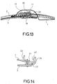
- the variant of the closure device shown in FIG. 13 comprises, for example on the end of the internal face of the leaf 1, under the zone 11, a part 17 having the general shape of a rectangular strip whose major axis is parallel to the axis of the drum, and whose lined end by the long side facing the hinge of this leaf is rolled up on itself to form a kind of tube 18 whose axis is in the same plane as the plane part 17.
- the outside diameter of this tube 18 is for example between 5 and 10 mm approximately.
- Exhibit 19 integral with the end of the outer face of the leaf 3, is in the form general of a rectangular strip whose major axis is parallel to the axis of the drum, the end of which, bordered by the long side facing the leaf 1 hinge, is rolled up on itself to form a sort of gutter 20 having, in section, a semi-circular shape.
- the diameter of the gutter 20 is practically equal to the outside diameter of tube 18.
- the dimensions of parts 17 and 19 and their relative arrangements are such that in the closed state of leaves 1 and 3 the tube 18 penetrates to the bottom of the hollow formed by the gutter 20.
- the operation of this device closure is similar to that described above with reference to Figures 3 to 12.
- the leaf 1 door a part 21 formed from a rectangular bar, one of which is folded large edges 22 or both at an angle of about 120 ° along a radius curvature of about 3 to 5 mm.
- the leaf 3 carries a part 23 formed at from a rectangular bar (whose axis is parallel to the axis of the drum when it is fixed on the leaf 3) of which one of the large edges is folded towards the outside of the leaf 3 to form a gutter 24 which comes to marry the face outer edge 22 in the locked position of the closure device.
- the device of the invention makes it possible to hide perfectly, in the closed state of the leaves, the elements of the device for closing the , which not only ensures a more aesthetic appearance to the drum closed, but avoids accidental contact of the user's hands or the laundry with the closing device when handling the drum.
Landscapes
- Engineering & Computer Science (AREA)
- Textile Engineering (AREA)
- Main Body Construction Of Washing Machines And Laundry Dryers (AREA)
- Detail Structures Of Washing Machines And Dryers (AREA)
- Wing Frames And Configurations (AREA)
Description
- les figures 1 et 2 sont respectivement une vue de dessus, et une vue en coupe selon II-II de la figure 1, de l'un des battants d'un tambour de machine à laver comportant une partie emboutie conformément à l'invention ;
- les figures 3 à 7 sont des vues en coupe simplifiées des deux battants d'un tambour de machine à laver conformes à l'invention, montrant diverses étapes successives de la fermeture de ce tambour ;
- les figures 8 à 12 sont des vues en coupe simplifiées des deux battants d'un tambour de machine à laver, conformes à l'invention, montrant diverses étapes successives de l'ouverture de ce tambour ; et
- les figures 13 et 14 sont des vues partielles de battants conformes à l'invention, munis de variantes de dispositifs de fermeture à encliquetage.
Claims (7)
- Dispositif de fermeture de sécurité pour battants (1, 3) de tambour de machine à laver le linge, du type à deux parties (13, 16 - 18, 20 - 22, 23) à encliquetage mutuel, dont l'une (13, 18, 22) est solidaire de l'un des battants (1), et l'autre (16, 20, 23) du second battant (3), caractérisé par le fait que l'un au moins des battants (1) comporte une partie en relief (11) masquant, lorsque le tambour est fermé, le dispositif de fermeture, et que l'extrémité (2) de ce battant recouvre l'extrémité de l'autre battant à l'état fermé du tambour.
- Dispositif selon la revendication 1, caractérisé par le fait que la partie en relief est une partie convexe obtenue par emboutissage d'une zone délimitée (11) du battant recouvrant partiellement l'autre (1) lorsque le tambour est fermé.
- Dispositif selon la revendication 1, caractérisé par le fait que la partie en relief est une partie concave obtenue par emboutissage d'une zone délimitée du battant (3) partiellement recouvert par l'autre lorsque le tambour est fermé.
- Dispositif selon la revendication 1, caractérisé par le fait que la partie en relief est une partie convexe de l'extrémité du battant recouvrant partiellement l'autre, et une partie concave de l'extrémité de l'autre battant, ces parties concave et convexe étant obtenues par cintrage des extrémités des deux battants.
- Dispositif selon la revendication 1, caractérisé par le fait que la partie en relief est une pièce rapportée masquant une ouverture pratiquée dans le battant, l'une des deux parties du dispositif de fermeture, fixée sur ce battant, pénétrant partiellement dans l'ouverture.
- Dispositif selon l'une des revendications précédentes, caractérisé par le fait que le battant recouvrant partiellement l'autre comporte une zone concave (4) servant de zone d'appui pour fermer les deux battants.
- Dispositif selon la revendication 6, caractérisé par le fait que la zone d'appui est sensiblement centrée par rapport à la largeur du battant et que sa largeur est inférieure à celle du battant, et par le fait que le battant comporte d'autres zones embouties concaves (8, 9) de part et d'autre de la zone d'appui pour empêcher l'éjection d'objets entre les deux battants.
Applications Claiming Priority (2)
| Application Number | Priority Date | Filing Date | Title |
|---|---|---|---|
| FR9314866 | 1993-12-10 | ||
| FR9314866A FR2713676B1 (fr) | 1993-12-10 | 1993-12-10 | Dispositif de fermeture de sécurité pour battants de tambour de machine à laver le linge. |
Publications (2)
| Publication Number | Publication Date |
|---|---|
| EP0657573A1 EP0657573A1 (fr) | 1995-06-14 |
| EP0657573B1 true EP0657573B1 (fr) | 1999-01-27 |
Family
ID=9453801
Family Applications (1)
| Application Number | Title | Priority Date | Filing Date |
|---|---|---|---|
| EP94402800A Expired - Lifetime EP0657573B1 (fr) | 1993-12-10 | 1994-12-06 | Dispositif de fermeture de sécurité pour battants de tambour de machine à laver le linge |
Country Status (4)
| Country | Link |
|---|---|
| EP (1) | EP0657573B1 (fr) |
| DE (1) | DE69416281T2 (fr) |
| ES (1) | ES2126726T3 (fr) |
| FR (1) | FR2713676B1 (fr) |
Families Citing this family (1)
| Publication number | Priority date | Publication date | Assignee | Title |
|---|---|---|---|---|
| DE102011055090B3 (de) * | 2011-11-07 | 2012-12-27 | Miele & Cie. Kg | Wäschebehandlungsmaschine wie Waschmaschine oder Wäschetrockner |
Family Cites Families (4)
| Publication number | Priority date | Publication date | Assignee | Title |
|---|---|---|---|---|
| DE1249207B (fr) * | 1967-09-07 | |||
| FR1535335A (fr) * | 1966-08-31 | 1968-08-02 | Philips Nv | Dispositif de fermeture auto-verrouillant muni de charnières |
| DE2135396A1 (de) * | 1971-07-15 | 1973-01-25 | Licentia Gmbh | Trommeldeckelverschluss |
| IT1174951B (it) * | 1983-08-01 | 1987-07-01 | Zanussi A Spa Industrie | Cesto per macchina lavabiancheria a caricamento dall'alto |
-
1993
- 1993-12-10 FR FR9314866A patent/FR2713676B1/fr not_active Expired - Fee Related
-
1994
- 1994-12-06 EP EP94402800A patent/EP0657573B1/fr not_active Expired - Lifetime
- 1994-12-06 ES ES94402800T patent/ES2126726T3/es not_active Expired - Lifetime
- 1994-12-06 DE DE69416281T patent/DE69416281T2/de not_active Expired - Fee Related
Also Published As
| Publication number | Publication date |
|---|---|
| HK1010744A1 (en) | 1999-06-25 |
| DE69416281T2 (de) | 1999-06-02 |
| ES2126726T3 (es) | 1999-04-01 |
| EP0657573A1 (fr) | 1995-06-14 |
| DE69416281D1 (de) | 1999-03-11 |
| FR2713676B1 (fr) | 1996-01-05 |
| FR2713676A1 (fr) | 1995-06-16 |
Similar Documents
| Publication | Publication Date | Title |
|---|---|---|
| EP1861289B1 (fr) | Dispositif bistable d'ouverture-fermeture, et compartiment de rangement le comportant | |
| CH418523A (fr) | Boîte à fermeture inviolable | |
| FR2470578A1 (fr) | Pince pour crochets de cintres et housse a vetements ayant une telle pince | |
| EP3718429A1 (fr) | Insert pour un bracelet de montre | |
| FR2713896A1 (fr) | Monture de barrette. | |
| FR2513578A1 (fr) | Pare-soleil, notamment pour vehicule automobile | |
| FR2970239A1 (fr) | Emballage equipe d'un dispositif d'ouverture et de fermeture etanche | |
| FR2694872A1 (fr) | Barrette à cheveux. | |
| FR2898928A1 (fr) | Tente comportant une toile souple et des moyens d'armature et ensemble la comportant | |
| EP0657573A1 (fr) | Dispositif de fermeture de sécurité pour battants de tambour de machine à laver le linge | |
| BE1006311A3 (fr) | Boite de boisson comportant un fond superieur a fermeture semi-arrachable. | |
| EP0857448B1 (fr) | Grille de cuisson à panneaux articulés | |
| EP0608580A1 (fr) | Boucle de fermeture | |
| FR2700724A1 (fr) | Etui pour une série d'outils, notamment de clés mâles coudées. | |
| BE527046A (fr) | ||
| FR2635653A1 (fr) | Barrette a cheveux | |
| FR2715381A1 (fr) | Récipient muni d'une capsule de fermeture inviolable. | |
| CH319199A (fr) | Curseur pour fermeture à curseur | |
| EP1810584B1 (fr) | Passant-bloqueur de cordon | |
| CH435006A (fr) | Dispositif d'ouverture incorporé à un récipient | |
| FR2549124A1 (fr) | Charniere a systeme de rappel incorpore et organe quelconque equipe de cette charniere | |
| WO2000000054A1 (fr) | Dispositif d'extension pour sac | |
| BE503162A (fr) | ||
| EP1082264A1 (fr) | Ustensile pour deboucher des recipients a couvercle visse | |
| CH313278A (fr) | Boîte munie d'une poignée porteuse et d'un fermoir |
Legal Events
| Date | Code | Title | Description |
|---|---|---|---|
| PUAI | Public reference made under article 153(3) epc to a published international application that has entered the european phase |
Free format text: ORIGINAL CODE: 0009012 |
|
| AK | Designated contracting states |
Kind code of ref document: A1 Designated state(s): DE ES FR GB IT SE |
|
| 17P | Request for examination filed |
Effective date: 19951207 |
|
| 17Q | First examination report despatched |
Effective date: 19970127 |
|
| GRAG | Despatch of communication of intention to grant |
Free format text: ORIGINAL CODE: EPIDOS AGRA |
|
| GRAG | Despatch of communication of intention to grant |
Free format text: ORIGINAL CODE: EPIDOS AGRA |
|
| GRAG | Despatch of communication of intention to grant |
Free format text: ORIGINAL CODE: EPIDOS AGRA |
|
| GRAH | Despatch of communication of intention to grant a patent |
Free format text: ORIGINAL CODE: EPIDOS IGRA |
|
| GRAH | Despatch of communication of intention to grant a patent |
Free format text: ORIGINAL CODE: EPIDOS IGRA |
|
| GRAA | (expected) grant |
Free format text: ORIGINAL CODE: 0009210 |
|
| AK | Designated contracting states |
Kind code of ref document: B1 Designated state(s): DE ES FR GB IT SE |
|
| PG25 | Lapsed in a contracting state [announced via postgrant information from national office to epo] |
Ref country code: SE Free format text: THE PATENT HAS BEEN ANNULLED BY A DECISION OF A NATIONAL AUTHORITY Effective date: 19990127 |
|
| ITF | It: translation for a ep patent filed | ||
| REF | Corresponds to: |
Ref document number: 69416281 Country of ref document: DE Date of ref document: 19990311 |
|
| REG | Reference to a national code |
Ref country code: ES Ref legal event code: FG2A Ref document number: 2126726 Country of ref document: ES Kind code of ref document: T3 |
|
| GBT | Gb: translation of ep patent filed (gb section 77(6)(a)/1977) |
Effective date: 19990330 |
|
| PGFP | Annual fee paid to national office [announced via postgrant information from national office to epo] |
Ref country code: GB Payment date: 19991118 Year of fee payment: 6 |
|
| PLBE | No opposition filed within time limit |
Free format text: ORIGINAL CODE: 0009261 |
|
| STAA | Information on the status of an ep patent application or granted ep patent |
Free format text: STATUS: NO OPPOSITION FILED WITHIN TIME LIMIT |
|
| 26N | No opposition filed | ||
| PG25 | Lapsed in a contracting state [announced via postgrant information from national office to epo] |
Ref country code: GB Free format text: LAPSE BECAUSE OF NON-PAYMENT OF DUE FEES Effective date: 20001206 |
|
| GBPC | Gb: european patent ceased through non-payment of renewal fee |
Effective date: 20001206 |
|
| REG | Reference to a national code |
Ref country code: FR Ref legal event code: TP |
|
| PGFP | Annual fee paid to national office [announced via postgrant information from national office to epo] |
Ref country code: DE Payment date: 20080110 Year of fee payment: 14 |
|
| PGFP | Annual fee paid to national office [announced via postgrant information from national office to epo] |
Ref country code: IT Payment date: 20081231 Year of fee payment: 15 |
|
| PG25 | Lapsed in a contracting state [announced via postgrant information from national office to epo] |
Ref country code: DE Free format text: LAPSE BECAUSE OF NON-PAYMENT OF DUE FEES Effective date: 20090701 |
|
| PGFP | Annual fee paid to national office [announced via postgrant information from national office to epo] |
Ref country code: FR Payment date: 20110110 Year of fee payment: 17 |
|
| PG25 | Lapsed in a contracting state [announced via postgrant information from national office to epo] |
Ref country code: IT Free format text: LAPSE BECAUSE OF NON-PAYMENT OF DUE FEES Effective date: 20091206 |
|
| PGFP | Annual fee paid to national office [announced via postgrant information from national office to epo] |
Ref country code: ES Payment date: 20101221 Year of fee payment: 17 |
|
| REG | Reference to a national code |
Ref country code: FR Ref legal event code: CD Owner name: FAGORBRANDT SAS, FR Effective date: 20110826 |
|
| REG | Reference to a national code |
Ref country code: ES Ref legal event code: PC2A Owner name: FAGORBRANDT SAS Effective date: 20111021 |
|
| REG | Reference to a national code |
Ref country code: FR Ref legal event code: ST Effective date: 20120831 |
|
| PG25 | Lapsed in a contracting state [announced via postgrant information from national office to epo] |
Ref country code: FR Free format text: LAPSE BECAUSE OF NON-PAYMENT OF DUE FEES Effective date: 20120102 |
|
| REG | Reference to a national code |
Ref country code: ES Ref legal event code: FD2A Effective date: 20130703 |
|
| PG25 | Lapsed in a contracting state [announced via postgrant information from national office to epo] |
Ref country code: ES Free format text: LAPSE BECAUSE OF NON-PAYMENT OF DUE FEES Effective date: 20111207 |