EP0657096B1 - Cultivating tray for growing plantlets - Google Patents
Cultivating tray for growing plantlets Download PDFInfo
- Publication number
- EP0657096B1 EP0657096B1 EP94101766A EP94101766A EP0657096B1 EP 0657096 B1 EP0657096 B1 EP 0657096B1 EP 94101766 A EP94101766 A EP 94101766A EP 94101766 A EP94101766 A EP 94101766A EP 0657096 B1 EP0657096 B1 EP 0657096B1
- Authority
- EP
- European Patent Office
- Prior art keywords
- pots
- cultivating tray
- supports
- outermost
- row
- Prior art date
- Legal status (The legal status is an assumption and is not a legal conclusion. Google has not performed a legal analysis and makes no representation as to the accuracy of the status listed.)
- Expired - Lifetime
Links
Images


Classifications
-
- A—HUMAN NECESSITIES
- A01—AGRICULTURE; FORESTRY; ANIMAL HUSBANDRY; HUNTING; TRAPPING; FISHING
- A01G—HORTICULTURE; CULTIVATION OF VEGETABLES, FLOWERS, RICE, FRUIT, VINES, HOPS OR SEAWEED; FORESTRY; WATERING
- A01G9/00—Cultivation in receptacles, forcing-frames or greenhouses; Edging for beds, lawn or the like
- A01G9/02—Receptacles, e.g. flower-pots or boxes; Glasses for cultivating flowers
- A01G9/029—Receptacles for seedlings
- A01G9/0295—Units comprising two or more connected receptacles
Abstract
Description
Die Erfindung betrifft eine Kulturplatte zum Züchten von Jungpflanzen mit in parallel zueinander angeordneten Reiben an der Deckplatte der Kulturplatte angeformten und gegenüber der Deckplatte nach unten orientierten Töpfen mit Löchern am Boden der Töpfe und mit einem von der Deckplatte nach unten gerichteten umlaufenden Rand.The invention relates to a culture plate for growing young plants with pots formed in parallel to one another on the cover plate of the culture plate and oriented downwards relative to the cover plate with holes in the bottom of the pots and with a peripheral edge directed downwards from the cover plate.
Eine herkömmliche Kulturplatte dieser Art weist in parallel zueinander angeordneten Reihen topfartige Vertiefungen bzw. Töpfe auf, die oben offen sind und an ihrem Boden eine Öffnung kleineren Durchmessers haben. Die kleinere Öffnung im Boden dient dazu, den durchwurzelten Preßballen zusammen mit der Jungpflanze von unten her aus der topfartigen Vertiefung herauszudrücken und überschüssiges Wasser ablaufen zu lassen. Diese Kulturplatte ist rechteckig ausgebildet und hat einen umlaufenden Rand (siehe FR-A-2 354 700).A conventional culture plate of this type has, in rows arranged parallel to one another, pot-like depressions or pots which are open at the top and have an opening of smaller diameter at their base. The smaller opening in the bottom serves to push the rooted bale together with the young plant out of the pot-like depression from below and to let excess water run off. This culture plate is rectangular and has a peripheral edge (see FR-A-2 354 700).
Der Erfindung liegt die Aufgabe zugrunde, eine Kulturplatte zu schaffen, von der mehrere ohne vertikalen Abstand voneinander leer und mehrere mit vertikalem Abstand voneinander mit Jungpflanzen zu deren Transport und Versand bepflanzt stapelbar sind und stabile Stapel größerer Höhen ermöglichen.The invention has for its object to provide a culture plate, several of which are empty without a vertical distance from one another and several which are planted at a vertical distance from one another with young plants for their transport and dispatch, and which enable stable stacks of greater heights.
Diese Aufgabe wird erfindungsgemäß dadurch gelöst, daß in der ersten Reihe anstelle der beiden äußersten Töpfe zwei Stützen sowie in der letzten Reihe anstelle der beiden zweitäußersten Töpfe zwei Stützen vorgesehen sind, die hohl und unten offen sowie nach oben orientiert sind, daß in der ersten Reihe die zwei zweitäußersten Töpfe am Boden je einen Stützring sowie in der letzten Reihe die zwei äußersten Töpfe am Boden je einen Stützring aufweisen und daß am oberen Ende der Stützen je ein Zentrierungsansatz vorgesehen ist.This object is achieved in that two supports are provided in the first row instead of the two outermost pots and two supports are provided in the last row instead of the two second outermost pots, which are hollow and open at the bottom and oriented upwards, that in the first row the two second outermost pots on the bottom each have a support ring and in the last row the two outermost pots on the bottom each have a support ring and that a centering projection is provided at the upper end of the supports.
Auf diese Weise gelangt man zu einer Kulturplatte zum Züchten von Jungpflanzen, die die vorstehend erwähnte Aufgabe voll erfüllt. Hinzu kommt, daß die einzelnen Kulturplatten selbst stabil sind und darüber hinaus auch die mit diesen Kulturplatten gebildeten Stapel ebenfalls sehr stabil sind, und zwar gestapelt mit vertikalem Abstand oder gestapelt ohne vertikalen Abstand voneinander.In this way, a culture plate for growing young plants is obtained which fully fulfills the task mentioned above. In addition, the individual culture plates themselves are stable and, moreover, the stacks formed with these culture plates are also very stable, namely stacked with a vertical spacing or stacked without a vertical spacing from one another.
In weiterer Ausgestaltung der Erfindung ist vorgesehen, daß die Stützen in ihren zur Kulturplatte hinweisenden Wänden je eine Öffnung aufweisen. Hierdurch wird ermöglicht, daß die Kulturplatte in den Öffnungen von Greifern einer Transportvorrichtung erfaßt, angehoben, bewegt und wieder abgesetzt wird.In a further embodiment of the invention it is provided that the supports each have an opening in their walls facing the culture plate. This enables the culture plate to be gripped, raised, moved and put down again in the openings by grippers of a transport device.
Zweckmäßig können die Stützringe am Boden der zwei äußersten und der zwei zweitäußersten Töpfe seitliche Ausnehmungen aufweisen. Hierdurch ist sichergestellt, daß überschüssiges Wasser aus diesen Töpfen durch die seitlichen Ausnehmungen ablaufen kann, wenn diese Töpfe in einem Stapel von Kulturplatten auf den gegenüberliegenden Stützen der darunter befindlichen Kulturplatte aufstehen.The support rings can expediently have lateral recesses at the bottom of the two outermost and the two second outermost pots. This ensures that excess water can drain from these pots through the lateral recesses when these pots stand in a stack of culture plates on the opposite supports of the culture plate below.
Des weiteren empfiehlt es sich, daß die Töpfe unterhalb der Deckplatte mit Stabilisierungsstegen verbunden sind.It is also recommended that the pots are connected with stabilizing bars below the cover plate.
Außerdem kann ein Teil der Stabilisierungsstege in einem bestimmten Muster jeweils um einen gleichen Betrag nach unten verlängert sein.In addition, a part of the stabilizing webs can be extended downwards in a certain pattern by an equal amount.
Des weiteren kann an den vier Seiten der Kulturplatte der umlaufende Rand je eine untere Aussparung aufweisen. Dadurch ist es möglich, die Kulturplatte mit Greifern einer Transportvorrichtung zu erfassen, anzuheben, zu bewegen und wieder abzusetzen.Furthermore, the peripheral edge can have a lower recess on each of the four sides of the culture plate. This makes it possible to grasp the culture plate with grippers of a transport device, to lift it, to move it and to set it down again.
Die Erfindung wird nachfolgend anhand eines in der Zeichnung dargestellten Ausführungsbeispieles des näheren erläutert. Es zeigt
- Fig. 1
- eine Ansicht auf die Kulturplatte von oben,
- Fig. 2
- eine Ansicht auf die Kulturplatte von unten,
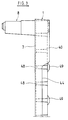
- Fig. 3
- eine Seitenansicht auf
Figur 1, - Fig. 4
- einen Schnitt längs der Linie IV-IV der
Figur 1 durch zwei ohne gegenseitigen Abstand aufeinander gestapelte Kulturplatten und - Fig. 5
- einen Schnitt längs der Linie V-V durch
Figur 1 durch zwei mit gegenseitigem Abstand aufeinander gestapelte Kulturplatten.
- Fig. 1
- a view of the culture plate from above,
- Fig. 2
- a view of the culture plate from below,
- Fig. 3
- 2 shows a side view of FIG. 1,
- Fig. 4
- a section along the line IV-IV of Figure 1 by two without mutually spaced culture plates and
- Fig. 5
- a section along the line VV through Figure 1 through two mutually spaced culture plates stacked.
Die in der Zeichnung dargestellte Kulturplatte 1 dient zum Züchten von Jungpflanzen. Sie ist als Rechteck ausgebildet und hat zwölf parallel zueinander angeordnete Reihen 2,3,4,5 mit jeweils neun Töpfen 6, die an der Deckplatte 7 der Kulturplatte 1 angeformt und gegenüber dieser nach unten ausgeformt sind.The
In der ersten Reihe 2 sind anstelle der beiden äußersten Töpfe zwei Stützen 8,9 vorgesehen, die an ihrem unteren Ende 10 offen und hohl ausgebildet sind. Die Stütze 8 ist in Höhe der Deckplatte 7 an der Kulturplatte 1 befestigt und nach oben unter Bildung einer unteren Stufe 11 und einer oberen Stufe 12 konisch ausgebildet. Zwischen der unteren Stufe 11 und der oberen Stufe 12 ist an den beiden von der Kulturplatte 1 aus nach außen gerichteten Wänden 13,14 der Stütze 8 ein Absatz 15 vorgesehen. Die beiden zur Kulturplatte 1 hin gewendeten Wände 16,17 sind eben.In the
Am oberen Ende 18 der Stütze 8 ist ein Zentrierungsansatz 19 vorgesehen, der aus einem zylindrischen unteren Zentrierungsteil 20 und einem zylindrischen oberen Zentrierungsteil 21 besteht, zwischen denen ein Absatz 22 vorgesehen ist. Die an der Wand 16 angrenzende Wand 17 der Stütze 8 hat eine Öffnung 23.At the
Die in der ersten Reihe 2 der Stütze 8 gegenüberliegend angeordnete Stütze 9 ist entsprechend der Stütze 8 ausgebildet. Zwischen den beiden Stützen 8 und 9 der ersten Reihe 2 sind sieben Töpfe 6 vorgesehen. Die übrigen Reihen mit Ausnahme der letzten Reihe 5 enthalten neun Töpfe 6. In der Deckplatte 7 sind zwischen den Töpfen 6 Öffnungen 24 vorgesehen.The
In der letzten Reihe 5 sind jeweils zwischen einem äußeren und fünf inneren Töpfen Stützen 25,26 vorgesehen. Die Stütze 25 hat eine Außenwand 27 und drei Innenwände 28,29,30 und ist in Höhe der Deckplatte 7 der Kulturplatte 1 an dieser befestigt. Die äußere Wand 27 hat einen unteren Bereich 31 und einen oberen Bereich 32, zwischen denen eine Stufe 33 vorgesehen ist. Am oberen Ende 34 der Stütze 25 ist ein Zentrierungsansatz 35 vorgesehen der aus einem unteren zylindrischen Teil 36 und einem oberen zylindrischen Teil 37 besteht, zwischen denen ein Absatz 38 vorgesehen ist.In the
Die nach innen orientierten Wände 28,29,30 sind eben ausgebildet. In der Wand 29 ist eine Öffnung 39 vorgesehen. Die in der untersten Reihe 5 gegenüberliegende Stütze 26 ist entsprechend der vorstehend beschriebenen Stütze 25 ausgebildet.The inwardly oriented
Wie insbesondere in Figur 2 dargestellt ist, hat die Kulturplatte einen umlaufenden Rand 40,41,42,43, in dem Ausnehmungen 44,45,46,47 vorgesehen sind. Jeder Topf 6 ist mit den Nachbartöpfen über Stabilisierungsstege 48 verbunden. Eine Anzahl von Stabilisierungsstegen 48 ist in einem bestimmten Muster über die Unterseite der Kulturplatte 1 verteilt mit nach unten gerichteten Verlängerungen 49 versehen, mit denen die Kulturplatte 1 auf dem Untergrund fest und stabil aufsteht.As is particularly shown in FIG. 2, the culture plate has a
Der der Stütze 8 benachbarte Topf hat an seinem Boden einen zylindrischen Stützring 50, der auf seinem Umfang verteilt mehrere Durchlässe 51 zum Ablauf von überschüssigem Wasser aufweist.The pot adjacent to the
In Figur 4 ist der Zustand dargestellt, in dem zwei Kulturplatten ohne Abstand zueinander gestapelt sind. Dabei ist die obere Kulturplatte so auf die untere aufgesetzt, daß die Stützen 8,9,25,26 die entsprechenden Stützen der unteren Kulturplatte übergreifen. Dabei liegt die obere Kulturplatte dicht auf der unteren Kulturplatte auf, so daß ein derart angeordneter Stapel einer Mehrzahl von Kulturplatten in der Höhe einen minimalen Raum einnimmt und über hohe Stabilität verfügt, so daß ein Umkippen eines auch sehr hoch gestapelten Stapels nicht zu befürchten ist.FIG. 4 shows the state in which two culture plates are stacked without a distance from one another. The upper culture plate is placed on the lower so that the supports 8,9,25,26 overlap the corresponding supports of the lower culture plate. The upper culture plate lies tightly on the lower culture plate, so that a stack of a plurality of culture plates arranged in this way occupies a minimal height and has high stability, so that there is no fear of a stack being stacked even very high.
In Figur 5 ist die obere Kulturplatte gegenüber der unteren Kulturplatte um 180° gewendet, so daß die obere Kulturplatte mit den Stützringen 50,52,53,54 auf den Stützen 8,9,25,26 der unteren Kulturplatte aufstehen, so daß die beiden Kulturplatten einen vertikalen Abstand der doppelten Höhe einer Kulturplatte haben. Auch in diesem gestapelten Zustand mehrere Kulturplatten ist der Stapel der Kulturplatten fest und stabil, so daß ein Umkippen auch eines sehr hoch gestapelten Stapels nicht zu befürchten ist.In Figure 5, the upper culture plate is turned 180 ° with respect to the lower culture plate, so that the upper culture plate with the
Die Öffnungen 23,39 in den Stützen 8,9,25,26 sind für Greifer einer in der Zeichnung nicht dargestellten Vorrichtung vorgesehen mit der die Kulturplatten angehoben, bewegt und wieder abgesetzt werden. Auch die in dem Rand 40,41,42,43 der Kulturplatte 1 vorgesehenen Ausnehmungen 44,45,46,47 sind vorgesehen, damit die Kulturplatte von den Greifern dieser Vorrichtung erfaßt werden können, mit der die Kulturplatte angehoben, bewegt und wieder abgesetzt wird.The
In dem in Figur 5 dargestellten Stapel mehrerer Kulturplatten mit Abstand übereinander steht die obere Kulturplatte mit dem Stützring 50 auf dem Boden 18 der Stütze 8 und ist durch den unteren Bereich 20 des Zentrierungsansatzes 19 zentriert. Außerdem greift der obere Teil 21 des Zentrierungsansatzes 19 durch die untere Öffnung 55 des Topfes 6. Hierdurch ist eine sichere Auflage und Zentrierung der oberen Kulturplatte auf der unteren Kulturplatte gewährleistet.In the stack of a plurality of culture plates shown at a distance from one another, the upper culture plate with the
Zur Bepflanzung der Kulturplatte werden die Töpfe 6 zunächst mit einem Preßballen Blumenerde gefüllt. Anschließend werden Stecklinge in die Preßballen eingepflanzt. Danach werden die Kulturplatten in einem Gewächshaus je nach Pflanzenart etwa drei Wochen kultiviert, d.h. bewurzelt. Nach beendetem Kultivieren werden die Kulturplatten aus dem Gewächshaus entnommen und wie in Figur 5 dargestellt gestapelt sowie in diesem Zustand zum Versand gebracht.To plant the culture plate, the
Claims (6)
- A cultivating tray for growing plantlets, having pots which are moulded on the cover tray of the cultivating tray, in rows arranged parallel to one another, and which are downwardly oriented in opposition to the cover tray and have holes in their bases, and having a peripheral edge which is directed downwards from the cover plate, characterized in that in the first row (2), instead of the two outermost pots, two supports (8, 9) are provided, and in the last row (5), instead of the two next to outermost pots, two supports (25, 26) are provided which are hollow and are downwardly open and upwardly oriented, in that in the first row (2) the two next to outermost pots each have at the base a supporting ring (50), and in the last row the two outermost pots each have at the base a supporting ring (50), and in that a respective centring piece (19) is provided at the upper end (18) of the supports (8, 9, 25, 26).
- A cultivating tray according to Claim 1, characterized in that the supports (8, 9, 25, 26) have in their walls (16, 17, 29) facing the cultivating tray (1) in each case an opening (23, 29).
- A cultivating tray according to Claim 1 or 2, characterized in that the supporting rings (50) at the base of the two outermost and the two next to outermost pots have lateral cutouts (51).
- A cultivating tray according to one of the preceding claims, characterized in that the pots (6) are connected to stabilizing webs (48) below the cover tray (7).
- A cultivating tray according to one of the preceding claims, characterized in that some of the stabilizing webs (48) are prolonged downwards in a particular pattern, in each case by the same amount.
- A cultivating tray according to one of the preceding claims, characterized in that the peripheral edge (40, 41, 42, 43) has on the four sides of the cultivating tray (1) a respective lower cutout (44, 45, 46, 47).
Applications Claiming Priority (2)
| Application Number | Priority Date | Filing Date | Title |
|---|---|---|---|
| DE9319024U | 1993-12-11 | ||
| DE9319024U DE9319024U1 (en) | 1993-12-11 | 1993-12-11 | Culture plate for growing young plants |
Publications (2)
| Publication Number | Publication Date |
|---|---|
| EP0657096A1 EP0657096A1 (en) | 1995-06-14 |
| EP0657096B1 true EP0657096B1 (en) | 1997-08-27 |
Family
ID=6901855
Family Applications (1)
| Application Number | Title | Priority Date | Filing Date |
|---|---|---|---|
| EP94101766A Expired - Lifetime EP0657096B1 (en) | 1993-12-11 | 1994-02-05 | Cultivating tray for growing plantlets |
Country Status (6)
| Country | Link |
|---|---|
| US (1) | US5426890A (en) |
| EP (1) | EP0657096B1 (en) |
| AT (1) | ATE157216T1 (en) |
| DE (2) | DE9319024U1 (en) |
| DK (1) | DK0657096T3 (en) |
| ES (1) | ES2108887T3 (en) |
Families Citing this family (28)
| Publication number | Priority date | Publication date | Assignee | Title |
|---|---|---|---|---|
| US5465843A (en) * | 1994-02-03 | 1995-11-14 | Rehrig Pacific Company | Nestable display crate for bottles or the like |
| US5855277A (en) * | 1994-02-03 | 1999-01-05 | Rehrig Pacific Company, Inc. | Nestable display crate for bottles with handle feature |
| DE9407266U1 (en) * | 1994-05-02 | 1994-07-07 | Poeppelmann Kunststoff | Plant range |
| USD379121S (en) * | 1995-04-18 | 1997-05-13 | Rehrig Pacific Company | Nestable crate with handle |
| USD380613S (en) * | 1995-04-18 | 1997-07-08 | Rehrig Pacific Company, Inc. | Wall structure for a nestable crate |
| US5678356A (en) * | 1996-03-07 | 1997-10-21 | Winstrip, Inc. | Apparatus for growing, planting and transplanting plants |
| DE19844020C2 (en) | 1998-09-25 | 2000-12-14 | Marga Duemmen | Culture plate for rooting young plants |
| US6385903B1 (en) | 1999-08-24 | 2002-05-14 | East Jordan Plastics, Inc. | Plug tray |
| KR100347590B1 (en) * | 2000-05-26 | 2002-08-07 | 전상집 | A seedling pot fixing frame |
| US7020997B1 (en) * | 2001-06-25 | 2006-04-04 | Container Slick, Inc. | Support system for potted plants |
| US6401960B1 (en) | 2001-06-29 | 2002-06-11 | Norseman Plastics Limited | Two liter bottle crate |
| US20040040923A1 (en) * | 2002-09-03 | 2004-03-04 | Wolff Gustave Fritz | Modular holders or candles, flowers or other items |
| BE1015126A3 (en) * | 2002-10-01 | 2004-10-05 | Willaert Patrick | Stackable crate for plants, has corner cells with fixed spacer elements to allow transport on pallets |
| US6966442B2 (en) | 2003-01-17 | 2005-11-22 | Rehrig Pacific Company | Stacking crates |
| NL1023336C2 (en) * | 2003-05-02 | 2004-11-03 | Modiform B V | Carrier for culture trays and assembly of at least one such carrier and culture tray. |
| US20080078119A1 (en) * | 2006-09-29 | 2008-04-03 | Hansen Thomas C | Plant starter cell container array rack |
| US20080115413A1 (en) * | 2006-11-20 | 2008-05-22 | Blackmore Company, Inc. | Horticulture tray |
| CA2701030C (en) | 2007-09-27 | 2015-11-10 | Orbis Canada Limited | Bottle crate |
| US20090119987A1 (en) * | 2007-10-15 | 2009-05-14 | John Ingrassia | Stackable nursery trays for plants |
| US7793783B2 (en) | 2008-06-18 | 2010-09-14 | Orbis Canada Limited | Beverage crate with constant-diameter pockets |
| US20100230318A1 (en) * | 2009-03-13 | 2010-09-16 | Stahl Edward L | Multiple Cap Size Bottle Crate |
| EP2595524A4 (en) * | 2010-07-24 | 2014-01-08 | Alexandra Laray Abraham | Basin for use with commercial dish and glassware racks |
| EP2817233B1 (en) * | 2012-02-22 | 2017-12-20 | Syngenta Participations AG | Stackable crate for the transportation of living plant material. |
| CA2853385A1 (en) * | 2014-06-02 | 2015-12-02 | Agropur Cooperative | Compact stackable tray |
| USD749323S1 (en) | 2014-11-10 | 2016-02-16 | Orbis Corporation | Beverage crate |
| PT3682727T (en) * | 2019-01-21 | 2021-11-18 | Wegrow Germany Gmbh | Plant palette |
| US11603228B2 (en) * | 2019-10-10 | 2023-03-14 | P.R.A. Company | Reusable recyclable thermoformed shipping containers |
| CA3209035A1 (en) * | 2021-02-26 | 2022-09-01 | Silo Farms, Llc | Mushroom growing system and method |
Family Cites Families (12)
| Publication number | Priority date | Publication date | Assignee | Title |
|---|---|---|---|---|
| GB1383721A (en) * | 1972-03-30 | 1974-02-12 | Presentoir Seiller Le | Display unit |
| BE781867A (en) * | 1972-04-10 | 1972-10-10 | Bekaert Sa Nv | DRAADKRAT. |
| NL7406925A (en) * | 1974-05-22 | 1975-11-25 | Hordijk Beheer B V | Plant growing and transport holder - has recesses in honeycomb pattern in flat portion and walls extending downwards |
| US3997057A (en) * | 1974-12-06 | 1976-12-14 | Keyes Fibre Company | Stacking means for packing tray |
| NL7606555A (en) * | 1976-06-17 | 1977-12-20 | Curver Bv | GROWTH HOLDER. |
| NL7613359A (en) * | 1976-12-01 | 1978-06-05 | Curver Bv | Plate-type flowerpot holder - has hollow oblong tapering supporting components extending each side and open=ended |
| US4101049A (en) * | 1977-03-10 | 1978-07-18 | Hopple Plastics, Inc. | Shipping tray for fruit |
| US4329813A (en) * | 1980-06-03 | 1982-05-18 | Aaltosen Tehtaat Oy Sarvis | Substratus crate for plant cultivation and transportation |
| NL8100096A (en) * | 1981-01-10 | 1982-08-02 | Curver Bv | STACKABLE HOLDER FOR BREEDING. |
| IT207739Z2 (en) * | 1985-08-09 | 1988-02-08 | Resma Srl | CONTAINMENT STRUCTURE PARTICULARLY FOR HORTICULTURAL-FLORAL PLANTS. |
| EP0254434A3 (en) * | 1986-07-17 | 1989-05-10 | Smithers-Oasis Co | Grower unit for the asexual vegetative propagation of plant cuttings |
| IE64543B1 (en) * | 1990-02-12 | 1995-08-23 | Ferdia Research Limited | A nestable and stackable tray |
-
1993
- 1993-12-11 DE DE9319024U patent/DE9319024U1/en not_active Expired - Lifetime
-
1994
- 1994-02-05 EP EP94101766A patent/EP0657096B1/en not_active Expired - Lifetime
- 1994-02-05 DK DK94101766.7T patent/DK0657096T3/en active
- 1994-02-05 DE DE59403864T patent/DE59403864D1/en not_active Expired - Fee Related
- 1994-02-05 ES ES94101766T patent/ES2108887T3/en not_active Expired - Lifetime
- 1994-02-05 AT AT94101766T patent/ATE157216T1/en not_active IP Right Cessation
- 1994-08-08 US US08/287,353 patent/US5426890A/en not_active Expired - Lifetime
Also Published As
| Publication number | Publication date |
|---|---|
| ATE157216T1 (en) | 1997-09-15 |
| ES2108887T3 (en) | 1998-01-01 |
| US5426890A (en) | 1995-06-27 |
| EP0657096A1 (en) | 1995-06-14 |
| DE9319024U1 (en) | 1994-03-31 |
| DE59403864D1 (en) | 1997-10-02 |
| DK0657096T3 (en) | 1998-04-06 |
Similar Documents
| Publication | Publication Date | Title |
|---|---|---|
| EP0657096B1 (en) | Cultivating tray for growing plantlets | |
| DE3039996A1 (en) | NEGOTIABLE AND PACKABLE PLANTING SYSTEM | |
| WO2018141507A1 (en) | Tray for cultivating plants, and system comprising a tray and plant pot | |
| EP0578153B1 (en) | Propagation tray, especially for forest plants | |
| DE2318187C3 (en) | Pallet for holding potted and substrate plants | |
| WO2019161967A1 (en) | Plant tray | |
| EP0988783B1 (en) | Cultivation tray for rooting seedlings | |
| CH572301A5 (en) | Plastic plant container watering saucer - has parts joined by centering pins fitting in indentations in base | |
| DE3618833C2 (en) | Planters | |
| EP0056665B1 (en) | Stackable container for nursery stock | |
| DE102020125904A1 (en) | Carrier system for an automated cultivation of plants | |
| DE4228204A1 (en) | Inter-stacking carrying containers - have two opposing projections and two opposing recesses for stacking on top of each other or inside each other. | |
| WO2016192700A1 (en) | Pipette tip packaging | |
| EP3319414A1 (en) | Pallets for planting pots | |
| WO2023078964A1 (en) | Carrier system for growing plants, comprising a plurality of carriers | |
| DE202019100061U1 (en) | Stackable plant pot | |
| DE3707476A1 (en) | Process and apparatus for cultivating plants | |
| DE202020000901U1 (en) | Stack & nest culture tray | |
| DE3312330A1 (en) | Device for mechanising pot gardening | |
| DE2046325A1 (en) | Containers for the cultivation and storage of flower bulbs and tubers | |
| EP3883362B1 (en) | Greenhouse arrangement | |
| EP3682727B1 (en) | Plant palette | |
| EP0150267B1 (en) | Tray for raising seed | |
| WO2022018236A1 (en) | Cultivating device for plants and a climate-controlled climate cell for cultivating plants using a cultivating device | |
| DE1611940C (en) | Package for holding containers |
Legal Events
| Date | Code | Title | Description |
|---|---|---|---|
| PUAI | Public reference made under article 153(3) epc to a published international application that has entered the european phase |
Free format text: ORIGINAL CODE: 0009012 |
|
| AK | Designated contracting states |
Kind code of ref document: A1 Designated state(s): AT BE CH DE DK ES FR GB IT LI NL PT SE |
|
| 17P | Request for examination filed |
Effective date: 19951207 |
|
| GRAG | Despatch of communication of intention to grant |
Free format text: ORIGINAL CODE: EPIDOS AGRA |
|
| 17Q | First examination report despatched |
Effective date: 19961025 |
|
| GRAH | Despatch of communication of intention to grant a patent |
Free format text: ORIGINAL CODE: EPIDOS IGRA |
|
| GRAH | Despatch of communication of intention to grant a patent |
Free format text: ORIGINAL CODE: EPIDOS IGRA |
|
| GRAA | (expected) grant |
Free format text: ORIGINAL CODE: 0009210 |
|
| AK | Designated contracting states |
Kind code of ref document: B1 Designated state(s): AT BE CH DE DK ES FR GB IT LI NL PT SE |
|
| REF | Corresponds to: |
Ref document number: 157216 Country of ref document: AT Date of ref document: 19970915 Kind code of ref document: T |
|
| REG | Reference to a national code |
Ref country code: CH Ref legal event code: EP |
|
| REF | Corresponds to: |
Ref document number: 59403864 Country of ref document: DE Date of ref document: 19971002 |
|
| ITF | It: translation for a ep patent filed |
Owner name: BARZANO' E ZANARDO MILANO S.P.A. |
|
| ET | Fr: translation filed | ||
| GBT | Gb: translation of ep patent filed (gb section 77(6)(a)/1977) |
Effective date: 19971021 |
|
| REG | Reference to a national code |
Ref country code: CH Ref legal event code: NV Representative=s name: PATENTANWAELTE SCHAAD, BALASS, MENZL & PARTNER AG |
|
| REG | Reference to a national code |
Ref country code: ES Ref legal event code: FG2A Ref document number: 2108887 Country of ref document: ES Kind code of ref document: T3 |
|
| REG | Reference to a national code |
Ref country code: PT Ref legal event code: SC4A Free format text: AVAILABILITY OF NATIONAL TRANSLATION Effective date: 19971023 |
|
| REG | Reference to a national code |
Ref country code: DK Ref legal event code: T3 |
|
| PLBE | No opposition filed within time limit |
Free format text: ORIGINAL CODE: 0009261 |
|
| STAA | Information on the status of an ep patent application or granted ep patent |
Free format text: STATUS: NO OPPOSITION FILED WITHIN TIME LIMIT |
|
| 26N | No opposition filed | ||
| REG | Reference to a national code |
Ref country code: GB Ref legal event code: IF02 |
|
| PGFP | Annual fee paid to national office [announced via postgrant information from national office to epo] |
Ref country code: GB Payment date: 20050125 Year of fee payment: 12 |
|
| PGFP | Annual fee paid to national office [announced via postgrant information from national office to epo] |
Ref country code: PT Payment date: 20050204 Year of fee payment: 12 |
|
| PG25 | Lapsed in a contracting state [announced via postgrant information from national office to epo] |
Ref country code: IT Free format text: LAPSE BECAUSE OF NON-PAYMENT OF DUE FEES;WARNING: LAPSES OF ITALIAN PATENTS WITH EFFECTIVE DATE BEFORE 2007 MAY HAVE OCCURRED AT ANY TIME BEFORE 2007. THE CORRECT EFFECTIVE DATE MAY BE DIFFERENT FROM THE ONE RECORDED. Effective date: 20050205 |
|
| PGFP | Annual fee paid to national office [announced via postgrant information from national office to epo] |
Ref country code: FR Payment date: 20050216 Year of fee payment: 12 |
|
| PGFP | Annual fee paid to national office [announced via postgrant information from national office to epo] |
Ref country code: AT Payment date: 20050218 Year of fee payment: 12 |
|
| PGFP | Annual fee paid to national office [announced via postgrant information from national office to epo] |
Ref country code: SE Payment date: 20050221 Year of fee payment: 12 Ref country code: CH Payment date: 20050221 Year of fee payment: 12 |
|
| PGFP | Annual fee paid to national office [announced via postgrant information from national office to epo] |
Ref country code: ES Payment date: 20050224 Year of fee payment: 12 |
|
| PG25 | Lapsed in a contracting state [announced via postgrant information from national office to epo] |
Ref country code: GB Free format text: LAPSE BECAUSE OF NON-PAYMENT OF DUE FEES Effective date: 20060205 Ref country code: AT Free format text: LAPSE BECAUSE OF NON-PAYMENT OF DUE FEES Effective date: 20060205 |
|
| PG25 | Lapsed in a contracting state [announced via postgrant information from national office to epo] |
Ref country code: SE Free format text: LAPSE BECAUSE OF NON-PAYMENT OF DUE FEES Effective date: 20060206 Ref country code: ES Free format text: LAPSE BECAUSE OF NON-PAYMENT OF DUE FEES Effective date: 20060206 |
|
| PGFP | Annual fee paid to national office [announced via postgrant information from national office to epo] |
Ref country code: NL Payment date: 20060215 Year of fee payment: 13 |
|
| PGFP | Annual fee paid to national office [announced via postgrant information from national office to epo] |
Ref country code: BE Payment date: 20060221 Year of fee payment: 13 |
|
| PGFP | Annual fee paid to national office [announced via postgrant information from national office to epo] |
Ref country code: DK Payment date: 20060222 Year of fee payment: 13 |
|
| PG25 | Lapsed in a contracting state [announced via postgrant information from national office to epo] |
Ref country code: LI Free format text: LAPSE BECAUSE OF NON-PAYMENT OF DUE FEES Effective date: 20060228 Ref country code: CH Free format text: LAPSE BECAUSE OF NON-PAYMENT OF DUE FEES Effective date: 20060228 |
|
| PGFP | Annual fee paid to national office [announced via postgrant information from national office to epo] |
Ref country code: DE Payment date: 20060228 Year of fee payment: 13 |
|
| PG25 | Lapsed in a contracting state [announced via postgrant information from national office to epo] |
Ref country code: PT Free format text: LAPSE BECAUSE OF NON-PAYMENT OF DUE FEES Effective date: 20060807 |
|
| REG | Reference to a national code |
Ref country code: PT Ref legal event code: MM4A Effective date: 20060807 |
|
| REG | Reference to a national code |
Ref country code: CH Ref legal event code: PL |
|
| EUG | Se: european patent has lapsed | ||
| GBPC | Gb: european patent ceased through non-payment of renewal fee |
Effective date: 20060205 |
|
| REG | Reference to a national code |
Ref country code: FR Ref legal event code: ST Effective date: 20061031 |
|
| REG | Reference to a national code |
Ref country code: ES Ref legal event code: FD2A Effective date: 20060206 |
|
| REG | Reference to a national code |
Ref country code: DK Ref legal event code: EBP |
|
| NLV4 | Nl: lapsed or anulled due to non-payment of the annual fee |
Effective date: 20070901 |
|
| BERE | Be: lapsed |
Owner name: *DUMMEN GUNTER Effective date: 20070228 |
|
| PG25 | Lapsed in a contracting state [announced via postgrant information from national office to epo] |
Ref country code: BE Free format text: LAPSE BECAUSE OF NON-PAYMENT OF DUE FEES Effective date: 20070228 |
|
| PG25 | Lapsed in a contracting state [announced via postgrant information from national office to epo] |
Ref country code: NL Free format text: LAPSE BECAUSE OF NON-PAYMENT OF DUE FEES Effective date: 20070901 Ref country code: FR Free format text: LAPSE BECAUSE OF NON-PAYMENT OF DUE FEES Effective date: 20060228 Ref country code: DK Free format text: LAPSE BECAUSE OF NON-PAYMENT OF DUE FEES Effective date: 20070228 Ref country code: DE Free format text: LAPSE BECAUSE OF NON-PAYMENT OF DUE FEES Effective date: 20070901 |
|
| PGFP | Annual fee paid to national office [announced via postgrant information from national office to epo] |
Ref country code: IT Payment date: 20060228 Year of fee payment: 13 |
|
| PGRI | Patent reinstated in contracting state [announced from national office to epo] |
Ref country code: IT Effective date: 20080301 |
|
| PGRI | Patent reinstated in contracting state [announced from national office to epo] |
Ref country code: IT Effective date: 20080301 |