EP0655219B1 - Appareil de mesure de la pression sanguine par méthode oscillométrique - Google Patents
Appareil de mesure de la pression sanguine par méthode oscillométrique Download PDFInfo
- Publication number
- EP0655219B1 EP0655219B1 EP94111064A EP94111064A EP0655219B1 EP 0655219 B1 EP0655219 B1 EP 0655219B1 EP 94111064 A EP94111064 A EP 94111064A EP 94111064 A EP94111064 A EP 94111064A EP 0655219 B1 EP0655219 B1 EP 0655219B1
- Authority
- EP
- European Patent Office
- Prior art keywords
- cuff
- pulse wave
- subject
- waveform
- pressure
- Prior art date
- Legal status (The legal status is an assumption and is not a legal conclusion. Google has not performed a legal analysis and makes no representation as to the accuracy of the status listed.)
- Expired - Lifetime
Links
Images


Classifications
-
- A—HUMAN NECESSITIES
- A61—MEDICAL OR VETERINARY SCIENCE; HYGIENE
- A61B—DIAGNOSIS; SURGERY; IDENTIFICATION
- A61B5/00—Measuring for diagnostic purposes; Identification of persons
- A61B5/02—Detecting, measuring or recording pulse, heart rate, blood pressure or blood flow; Combined pulse/heart-rate/blood pressure determination; Evaluating a cardiovascular condition not otherwise provided for, e.g. using combinations of techniques provided for in this group with electrocardiography or electroauscultation; Heart catheters for measuring blood pressure
- A61B5/021—Measuring pressure in heart or blood vessels
- A61B5/02108—Measuring pressure in heart or blood vessels from analysis of pulse wave characteristics
- A61B5/02116—Measuring pressure in heart or blood vessels from analysis of pulse wave characteristics of pulse wave amplitude
-
- A—HUMAN NECESSITIES
- A61—MEDICAL OR VETERINARY SCIENCE; HYGIENE
- A61B—DIAGNOSIS; SURGERY; IDENTIFICATION
- A61B5/00—Measuring for diagnostic purposes; Identification of persons
- A61B5/02—Detecting, measuring or recording pulse, heart rate, blood pressure or blood flow; Combined pulse/heart-rate/blood pressure determination; Evaluating a cardiovascular condition not otherwise provided for, e.g. using combinations of techniques provided for in this group with electrocardiography or electroauscultation; Heart catheters for measuring blood pressure
- A61B5/021—Measuring pressure in heart or blood vessels
- A61B5/022—Measuring pressure in heart or blood vessels by applying pressure to close blood vessels, e.g. against the skin; Ophthalmodynamometers
Definitions
- the present invention relates to an oscillometric blood pressure measuring apparatus according to the preamble of claim 1 which detects a pulse wave of a living subject and enables a doctor to make a diagnosis based on the waveform of the pulse wave.
- the waveform of a pulse wave produced from an artery of a living body or subject provides useful information reflecting the condition of blood circulation of the subject.
- various diagnosing apparatus which analyze the waveform of a pulse wave of a subject and make a diagnosis on the circulatory organ of the subject based on the analyzed results.
- the conventional diagnosing apparatus employ (a) an arterial catheter which is invasively inserted into an artery of a subject, and (b) a pressure sensor for directly detecting a pulse wave from inside the artery.
- U.S. Patent No. 5,238,000 or, for example, EP 0 297 146 discloses a pressure pulse wave sensor which is pressed on the skin of a subject for indirectly detecting a pressure pulse wave produced from an artery under the skin.
- direct pulse wave detecting technique it needs a skilled doctor to carry out the insertion of the catheter into the artery, and the arterial invasion due to the catheter insertion gives serious stress to the subject.
- indirect pulse wave detecting technique an exclusive pressure pulse wave sensor is needed, so that the overall apparatus becomes complicated and expensive. Also, it is more or less cumbersome to set the sensor on the skin of the subject.
- an oscillometric blood pressure measuring apparatus comprising (a) an inflatable cuff adapted to be wound around a body portion of a living subject; (b) an oscillometric blood pressure measuring device which supplies a fluid pressure to the cuff to press the body portion of the subject, detects variation of a plurality of pulse amplitudes of a pulse wave which is produced in the cuff in synchronism with heartbeat of the subject while the fluid pressure of the cuff is changed, and determines a blood pressure of the subject based on the variation of the pulse amplitudes; (c) a cuff pulse-wave detecting device which detects a pulse wave which is produced in the cuff when the fluid Pressure of the cuff takes a reference pressure value not higher than a mean blood pressure of the subject, and produces a pulse wave signal representative of the detected pulse wave; and (d) a waveform storing device including a waveform memory, for storing a waveform of a pulse wave of the
- the cuff pulse-wave detecting device detects a pulse wave ("cuff pulse wave") which is produced in the cuff when the fluid pressure of the cuff ("cuff pressure”) takes a reference pressure not higher than a mean blood pressure of the subject. Based on the pulse wave signal representative of the cuff pulse wave, the waveform storing device stores a waveform of a pulse wave of the subject in the waveform memory.
- the cuff pulse wave detected as the pressure oscillation produced in the cuff when the cuff pressure takes a reference pressure not higher than the mean blood pressure of the subject has substantially the same waveform as that of a pulse wave directly or invasively detected as the pressure oscillation produced in an artery of the subject.
- the present apparatus further comprises: a mean blood pressure measuring device which measures the mean blood pressure of the subject; and a cuff pressure holding device which holds the fluid pressure of the cuff at the reference pressure value not higher than the mean blood pressure of the subject measured by the mean blood pressure measuring device, wherein the cuff pulse-wave detecting device detects the pulse wave which is produced in the cuff when the fluid pressure of the cuff is held at the reference pressure value by the cuff pressure holding device. In this case, it is not necessary to remove, from the pulse wave detected from the cuff, detection errors which are introduced thereinto if the pulse wave is detected while the fluid pressure of the cuff is changed.
- the present apparatus detects a pulse wave of a living subject and enables a doctor to make a diagnosis based on the waveform of the pulse wave, in a non-invasive manner in which an invasive pulse wave detecting device is not used.
- a pulse wave diagnosis can be carried out with ease, at low cost, and without serious stress to the subject due to invasive pulse wave detection.
- the BP measuring apparatus further comprises an output device which outputs the waveform stored in the waveform memory, so that a doctor can make a diagnosis based on the output waveform.
- the output device may comprise at least one of (a) a display device which displays the waveform stored in the waveform memory and (b) a recording device which records, on a recording medium, the waveform stored in the waveform memory. Since the output waveform has substantially the same waveform as that of a pulse wave invasively detected from inside an artery of the subject, the doctor can make a correct diagnosis on the subject.
- the BP measuring apparatus further comprises waveform analyzer means for analyzing the waveform stored in the waveform memory, so that a doctor can make a diagnosis based on the analyzed results of the waveform analyzer means.
- the waveform analyzer means may operate for analyzing various parameters of the waveform according to various pulse wave diagnosis algorithms known in the art. Since the pulse wave stored in the waveform memory has substantially the same waveform as that of a pulse wave invasively detected from an artery of the subject, the doctor can make a correct diagnosis on the subject baked on the analyzed results.
- the cuff pulse-wave detecting device comprises means for detecting the pulse wave which is produced in the cuff when the fluid pressure of the cuff takes the reference pressure value within a pressure range between the mean blood pressure of the subject and a diastolic blood pressure of the subject.
- the mean blood pressure measuring device comprises means for measuring the mean blood pressure of the subject while the fluid pressure of the cuff is increased to a prescribed pressure value
- the cuff pressure holding means comprises means for holding the fluid pressure of the cuff at the reference pressure value not higher than the mean blood pressure of the subject while the fluid pressure of the cuff is decreased from the prescribed pressure value.
- the mean blood pressure measuring device comprises means for determining, as the mean blood pressure of the subject, a fluid pressure of the cuff at a time of detection of a pulse having a greatest amplitude of the respective amplitudes of a plurality of pulses of a pulse wave which is produced in the cuff while the fluid pressure of the cuff is changed.
- the mean blood pressure measuring device may comprise means for determining, as the mean blood pressure of the subject, a fluid pressure of the cuff at a time when a value of correlation between each pair of successive pulses of a plurality of pulses of a pulse wave which is produced in the cuff while the fluid pressure of the cuff is changed, is changed by a prescribed amount. In these cases, it is passible to measure the mean blood pressure of the subject without again inflating the cuff after deflating the same.
- the oscillometric blood pressure measuring device comprises: a pressure pulse wave sensor which detects a radial pulse wave produced from a radial artery of the subject; transfer function correcting means for correcting a standard transfer function from a pulse wave produced in an aorta of a standard human being to a pulse wave of the human being detected from the cuff by the cuff pulse-wave detecting device, based on the radial pulse wave of the subject detected by the pressure pulse wave sensor and the pulse wave of the subject detected from the cuff by the cuff pulse-wave detecting device; and calculating means for providing an estimated aortic pulse wave based on the pulse wave of the subject detected from the cuff by the cuff pulse-wave detecting device, according to the corrected transfer function provided by the transfer function correcting means, wherein the waveform storing device stores, in the waveform memory, the waveform of the aortic pulse wave provided by the calculating means.
- the BP measuring apparatus provides the reliable
- FIG. 1 there is shown an oscillometric blood pressure (BP) measuring apparatus embodying the present invention.
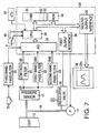
- Reference numeral 10 designates an inflatable cuff adapted to be wound around a body portion (e.g., upper arm) of a living subject (e.g., patient) so as to press the upper arm.
- the inflatable cuff 10 has a bag structure formed of an elastic sheet (e.g., rubber or vinyl sheet).
- the cuff 10 is connected via piping 18 to a pressure sensor 12, an air pump 14, and an air-deflation regulator valve 16.
- the pressure sensor 12 includes, for example, a semiconductor pressure sensing element (not shown) which detects an air pressure in the cuff 10 ("cuff pressure") and supplies a detection signal, SP, representative of the detected cuff pressure, to a low-pass filter 20, a first band-pass filter 22, and a second band-pass filter 23.
- the low-pass filter 20 permits only a DC (direct current) or static-pressure component of the detection signal SP to pass therethrough, thereby supplying a cuff-pressure signal, SK, representative of the detected static cuff pressure, to an analog to digital (A/D) converter 24.
- the first band-pass filter 22 permits only a 1 to 10 Hz frequency AC (alternating current) component of the detection signal SP to pass therethrough, thereby supplying a first pulse wave signal, SM1, representative of a pulse wave of the subject, to the A/D converter 24.
- the pulse wave is produced in the cuff 10 because of the pulsation of arteries in the upper arm in synchronism with heartbeat of the subject, while the cuff pressure falls within an appropriate pressure range.
- the pulse wave produced in the cuff 10 is obtained as the AC component of the detection signal SP supplied from the pressure sensor 12.
- the second band-pass filter 23 permits only a 0.5 to 20 Hz frequency AC component of the detection signal SP to pass therethrough, thereby supplying a second pulse wave signal, SM2, representative of the pulse wave of the subject, to the A/D converter 24.
- the first band-pass filter 22 has a narrow specific frequency range (e.g., 1 to 10 Hz) for obtaining, from the detection signal SP, successive pulse amplitudes free from artifact noise possibly introduced thereinto because of physical motion of the subject.
- the second band-pass filter 23 has a comparatively wide specific frequency range (e.g., 0.5 to 20 Hz) for obtaining, from the same signal SP, a pulse wave having a waveform similar to that of a pulse wave which is directly or invasively obtained from inside an artery of the subject.
- the A/D converter 24 has a time division multiplexer for time sharing of the three analog signals SK, SM1, SM2, and concurrently converts those analog signals to respective digital signals.
- the present BP measuring apparatus also has an arithmetic control device 26 which is essentially constituted by a microcomputer including a central processing unit (CPU) 28, a random access memory (RAM) 30, a read only memory (ROM) 32, a first output interface 34, and a second output interface 36.
- the CPU 28 receives the three digital signals SK, SM1, SM2 from the A/D converter 24, and processes those signals by utilizing the temporary-storage function of the RAM 30 and the various control programs pre-stored in the ROM 32, so that the CPU 28 controls the operations of the air pump 14 and the air-deflation regulator valve 16 through the first output interface 34 and controls an output device 38 through the second output interface 36.
- the output device 38 includes a printer which records, with an ink and on a recording sheet, the measured blood pressure (BP) values and detected pulse wave of the subject.
- the output device 38 also includes an image display 38a constituted by a number of light emitting elements (e.g., light emitting diodes).
- the image display 38a displays the measured blood pressure values and the waveform of detected pulse wave.
- a mode switch 40 is operable for selecting one of a BP measurement mode and a pulse wave diagnosis mode.
- the mode switch 40 selectively supplies one of a first signal indicative of the BP measurement mode and a second signal indicative of the pulse wave diagnosis mode, to the CPU 28.
- An ON/OFF switch 42 is operable for starting and stopping the present BP measuring apparatus, and alternatively supplies a START signal and a STOP signal to the CPU 28 upon operation thereof.
- the pressure sensor 12 detects a pulse wave which is produced in the cuff 10 wound around the upper arm of the subject in synchronism with heartbeat of the subject while the cuff pressure is changed.
- the control device 26 has a BP determining function or means 50 for determining a mean BP value of the subject; a cuff pressure holding function or means 52 for holding the cuff pressure at a reference pressure value not higher than the mean BP value of the subject; a waveform storing function or means 54 for storing a waveform of a pulse wave of the subject by utilizing a pulse wave which is produced in the cuff 10 when the cuff pressure is held at the reference pressure value not higher than the mean BP value of the subject; an output function or means 56 for operating the output device 38 to output the stored waveform so that a doctor can make a diagnosis based on the output waveform; and a waveform analyzing function or means 58 for analyzing the stored waveform so that a doctor can make a diagnosis based on the analyzed results.
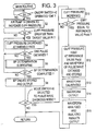
- Step S1 the CPU 28 of the control device 26 judges whether the ON/OFF switch 42 has been operated for starting the operation of the present apparatus, based on the START or STOP signal supplied from the switch 42. If a negative judgment is made at Step S1, the CPU 28 waits for receiving the START signal from the switch 42. Meanwhile, if a positive judgment is made at Step S1, the control of the CPU 28 proceeds with Step S2 to operate the air pump 14 so as to supply a pressurized air to the inflatable cuff 10 and thereby quickly increase the air pressure in the cuff 10, i.e., cuff pressure.
- Step S2 is followed by Step S3 to judge whether the cuff pressure has reached a prescribed target pressure value, Pt, (e.g., 180 mmHg) higher than a systolic blood pressure of the subject. If a negative judgment is made at Step S3, the CPU 28 repeats Steps S2 and S3. Meanwhile, if a positive judgment is made at Step S3, the control of the CPU 28 proceeds with Step S4 to change the degree of opening of the air-deflation regulator valve 16 so as to slowly deflate the cuff 10. This slow cuff deflation is carried out at a rate of 2 to 3 mmHg/sec, for example, that is suitable for a BP measurement.
- Pt e.g. 180 mmHg
- Step S4 is followed by Step S5 to judge whether the CPU 28 has received a span of signal SM1 corresponding to a pulse having an amplitude, i.e., corresponding to a heartbeat of the subject. If a negative judgment is made at Step S5, the CPU 28 repeats Steps S4 and S5.
- Step S5 the control of the CPU 28 proceeds with Step S6 to operate according to a known oscillometric BP determination algorithm, i.e., determine the BP values of the subject.
- Step S6 is followed by Step S7 to judge whether the BP determination routine at Step S6 has been completed. While the cuff pressure is slowly decreased, the respective amplitudes of successive pulses of the pulse wave first increase and then decrease. The amplitude of one pulse (“pulse amplitude”) is obtained by subtracting the lower-peak magnitude of the one-pulse signal SM1 from the upper-peak magnitude of the same.
- a cuff pressure at the time when the pulse amplitudes significantly largely increase is determined as a systolic BP value, Psys, of the subject; a cuff pressure at the time of detection of the greatest pulse amplitude is determined as a mean BP value, Pmean; and a cuff pressure at the time when the pulse amplitudes significantly largely decrease is determined as a diastolic BP value, Pdia.
- Step S7 the CPU 28 repeats Steps S4 through S7. Meanwhile, if a positive judgment is made at Step S7, the control of the CPU 28 proceeds with Step S8 to store the three BP values Psys, Pmean, Pdia in a BP data memory area 60 provided in the RAM 30, and display those BP values in digits on the image display 38a. Furthermore, the CPU 28 fully opens the air-deflation regulator valve 16 so as to quickly deflate the cuff 10, i.e., quickly decrease the cuff pressure and thereby release the subject's upper arm from the cuff pressure.
- Step S8 is followed by Step S9 to judge whether the pulse wave diagnosis mode has been selected, based on the mode signal supplied from the mode switch 40. If a negative judgment is made at Step S9, that is, if the present apparatus is selected to the BP measurement mode, the current control cycle is ended, and the control of the CPU 28 returns to Step S1 and the following.
- Step S9 if a positive judgment is made at Step S9, that is, if the present apparatus is selected to the pulse wave diagnosis mode, the control of the CPU 28 goes to Step S10 to close the air-deflation regulator valve 16 and operate the air pump 14 so as to supply a pressurized air to the cuff 10 and thereby increase the cuff pressure at the same rate as that employed at Step S2.
- Step S10 is followed by Step S11 to judge whether the cuff pressure has reached a reference pressure value, Phold, not higher than the mean BP value Pmean stored in the BP data memory area 60 of the RAM 30.
- the reference pressure Phold is selected at a value falling within a pressure range between the mean and diastolic BP values Pmean, Pdia, more preferably at a value equal to a cuff pressure at the time of detection of a pulse immediately before the pulse amplitudes largely decrease, that is, pulse preceding a pulse corresponding to the cuff pressure determined as the diastolic BP value Pdia. If a negative judgment is made at Step S11, the CPU 28 repeats Steps S10 and S11. On the other hand, if a positive judgment is made at Step S11, the control of the CPU 28 goes to Step S12.
- the CPU 28 stops the operation of the air pump 14 so as to hold the cuff pressure at the reference pressure value Phold, reads in at least one span of signal SM2 corresponding to at least one pulse of the cuff pulse wave, i.e., corresponding to at least one heartbeat of the subject, and stores waveform data representative of the waveform of the read-in pulse wave signal SM2 in a waveform memory area 62 of the RAM 30. Additionally, the CPU 28 opens the air-deflation regular valve 16 so as to quickly decrease the cuff pressure and thereby release the subject's upper arm from the cuff pressure.
- Step S12 is followed by Step S13 to calibrate the stored waveform with respect to blood pressure, on the assumption that the upper-peak magnitude of the waveform corresponds to the systolic BP value Psys and the lower-peak magnitude of the same corresponds to the diastolic BP value Pdia.
- the calibrated waveform represents instantaneous blood pressure values of the patient.
- the CPU 28 operates the output device 38 to display the calibrated waveform on the image display 38a and record the same on a recording sheet, so that a doctor or a heart specialist can make a diagnosis based on the output waveform.
- Step S14 is followed by Step S15 to analyze various parameters or characteristics of the waveform stored in the waveform memory area 62 at Step S12 and then calibrated at Step S13. That is, the CPU 28 quantifies the characteristics of the shape or profile of the waveform, according to known pulse wave diagnosis algorithms pre-stored in the ROM 32, and outputs the quantified values through the output device 38, so that a heart specialist can make a diagnosis based on the analyzed results. For example, the CPU 28 calculates a maximum differential or slope, (dp/dt) max , of an increasing portion of one-pulse waveform.
- the parameter (dp/dt) max relates to the strength of cardiac muscle and it is proportional to the cardiac output.
- Step S6 corresponds to the BP determining means 50 for determining the mean BP value Pmean of the subject
- Step S11 corresponds to the cuff pressure holding means 52 for holding the cuff pressure at the reference pressure value Phold not higher than the mean BP value Pmean
- the waveform memory area 62 of the RAM 30 corresponds to the waveform storing means 54 for storing the waveform of a pulse wave which is detected when the cuff pressure is held at the reference value Phold
- Step S14 corresponds to the output means 56 for operating the output device 38 to output the stored waveform so that a doctor or a heart specialist can make a diagnosis based on the output waveform.
- Step S15 corresponds to the waveform analyzing means 58 for analyzing the waveform stored in the waveform memory area 62 so that a doctor can make a diagnosis based on the analyzed results, for example, a heart specialist can diagnose on the condition of the circulatory organ of the subject based on the analyzed parameter (dp/dt) max and/or other analyzed parameters of the waveform.
- the present oscillometric BP measuring apparatus is capable of providing a reliable and accurate pulse wave of a living subject and enabling a doctor to make a diagnosis based on the waveform of the pulse wave, in a non-invasive manner in which an invasive pulse wave detecting device using an arterial catheter is not needed.
- a pulse wave diagnosis can be made with ease and safety and at low cost.
- the waveform of pulse wave is obtained while the cuff pressure is held at the reference value Phold, it is not necessary to remove, from the waveform, detection errors introduced thereinto in the case of obtaining the cuff pulse wave while the cuff pressure is continuously changed.
- the second embodiment has the same hardware construction as that of the first embodiment of Fig. 1, and operates according to the control program represented by the flow chart of Fig. 4 in place of Fig. 3 for the first embodiment.
- the same reference numerals and symbols as used for the first embodiment shown in Figs. 1 and 3 are used for designating the corresponding parts or steps for the second embodiment, and the description of those elements are omitted.
- Step S3 if a negative judgment is made at Step S3, the control of the CPU 28 goes to Step S16 to judge whether the CPU 28 has read in a pulse having the greatest amplitude of all the pulses obtained during the cuff pressure inflation effected at Steps S2 and S3. If a negative judgment is made at Step S16, the CPU 28 repeats Steps S2, S3, and S16.
- Step S17 the control of the CPU 28 proceeds with Step S17 to store, in the BP data memory area 60, a cuff pressure at the time of detection of the pulse having the greatest amplitude, as a mean BP value, Pmean, of the subject, and additionally determine a value not higher than the mean BP value Pmean, for example, value lower by 20 mmHg than the value Pmean, as a reference pressure value, Phold.
- Step S17 is followed by Step S2.
- Step S5 or S7 if a negative judgment is made at Step S5 or S7, the control of the CPU 28 goes to Step S18 to judge whether the cuff pressure has reached the reference value Phold. If a positive judgment is made at Step S18, the control proceeds with Step S19 to close the air-deflation regulator valve 16, hold the cuff pressure at the reference value Phold for a short time, read in the pulse wave signal SM2, and store the waveform of signal SM2 in the waveform memory area 62. Step S19 is followed by Step S4 to continue the slow cuff deflation.
- Fig. 5 is a time chart representing the change of the cuff pressure during the above-described steps.
- the oscillometric BP measuring apparatus advantageously obtains the BP values and pulse-wave-waveform of the subject during a one-time inflation and deflation of the cuff 10.
- the mean BP value Pmean of the subject is determined by finding a pulse having the greatest amplitude from the successive pulses of the pulse wave produced in the cuff 10 during the deflation or inflation of the cuff 10.
- the mean BP value Pmean of the subject may be determined by other methods. For example, it is possible to determine, as the mean BP value Pmean, a cuff pressure at the time when a value of correlation between each pair of successive pulses out of the individual pulses of the pulse wave produced in the cuff 10 while the cuff pressure is changed, is lowered by more than a prescribed magnitude or amount.
- the third embodiment relates to an oscillometric BP measuring apparatus like the first and second embodiments, and has a hardware construction similar to that of the apparatus of Fig. 1 wherein, however, the former is different from the latter in that the former additionally includes a pressure pulse wave sensor 70 and a third band-pass filter 72 to which the sensor 70 is connected.
- the pressure pulse wave sensor 70 has a press surface in which a plurality of pressure sensing elements (not shown) are provided, and the sensor 70 is set on the skin of a wrist or an ankle of the subject in such a way that the press surface of the sensor 70 is pressed against a radial artery or a pedal dorsal artery under the skin so as to detect a pressure pulse wave propagated from the artery to the pressure sensing elements in synchronism with heartbeat of the subject.
- the third band-pass filter 72 receives the output signal of the sensor 70, and permits only a pressure pulse wave component of the sensor signal to pass therethrough, thereby supplying a pressure pulse wave signal to the A/D converter 24.
- the present apparatus may operate according to the flow chart of Fig. 3 for the first embodiment or the flow chart of Fig. 4 for the second embodiment each of which, however, is modified by adding, after Step S12 of Fig. 3 or Step S19 of Fig. 4, Steps S20 through S23 shown in Fig. 8.
- Step S12 or at Step S19 the waveform of pulse wave detected from the cuff 10 (i.e., second pulse wave signal SM2) is stored in the waveform memory area 62 of the RAM 30.
- an aortic pulse wave is estimated by calculation based on the cuff pulse wave (i.e., signal SM2) obtained at Step S12 or Step S19, and the waveform of estimated aortic pulse wave is stored in a waveform memory area 62 of a RAM 30, so that the aortic pulse wave is output by an output device 38 or analyzed by a waveform analyzer means 58.
- the cuff pulse wave i.e., signal SM2
- a CPU 28 reads in the signal supplied from the pressure pulse wave sensor 70, that is, the waveform of pressure pulse wave detected from a single superficial artery (e.g., radial artery) of the subject.
- Step S20 is followed by Step S21 to calculate the difference between the cuff pulse wave detected from a cuff 10 wound around an upper arm of the subject, obtained at Step S12 or Step S19, and the radial pulse wave detected from the radial artery of the subject, obtained at Step S20.
- the difference between the two sorts of pulse waves may be defined as the area enveloped by a one-pulse signal SM2 and a corresponding one-pulse signal of the sensor 70.
- Step S21 is followed by Step S22 to determine two correcting values, a and b, of the following expression (2), based on the pulse-wave difference obtained at Step S21, according to predetermined relationships between the values a, b and the pulse-wave difference as shown in Fig. 9. These relationships are, e.g., function equations pre-stored in a ROM 32.
- the values a and b are small values which can vary depending upon the condition of arteries of the subject.
- Md(t) Mk(t) ⁇ 1/(aT + b)
- Step S22 is followed by Step S23 to estimate or calculate an aortic pulse wave Md(t) of the subject (e.g., one pulse), based on the cuff pulse wave Mk(t) (e.g., one pulse) stored in the waveform memory area 62 at Step S12 or Step S19, according to the above expression (2), and store the obtained waveform of aortic pulse wave Md(t) in the waveform memory area 62 in association with the waveform of cuff pulse wave Mk(t).
- the calibrated waveform is output by the output device 38 at Step S14 and is subjected to the pulse wave analysis at Step S15
- the aortic pulse wave Md(t) of the subject is obtained by calculation based on the cuff pulse wave Mk(t) of the same.
- the waveform of aortic pulse wave Md(t) is output and the automatic analysis is carried out based on the waveforn Md(t). Therefore, the output waveform and analyzed results become more accurate and reliable, which contributes to improving the doctor's diagnosis relying on the output waveform and/or analyzed results.
- each blood pressure measurement is carried out with or without a waveform detection and storing, in response to an "ON" operation of the ON/OFF switch 42
- the BP measuring apparatus it is possible to adapt the BP measuring apparatus to repeatedly carry out a blood pressure measurement with or without a waveform detection and storing at regular intervals of time.
- the blood pressure values and/or the waveform and analyzed results may be stored for each of the periodic operations, so that a doctor can utilize the stored data for obtaining not only one-day or 24-hour variation of the blood pressure values and pulse rates but also one-day variation of the analyzed waveform parameters.
- Step S13 it is possible to insert, after Step S13, an additional step where the CPU 28 determines a different sort of mean BP value, Pmean s , of the subject by integrating the cuff or aortic pulse wave calibrated at Step S13 (specifically, a cuff pressure corresponding to the gravity center of the integration, i.e., area of the cuff or aortic pulse wave is determined as the mean value Pmean s ), and evaluates the reliability of oscillometric blood pressure measurement carried out at Step S6, by comparing the thus obtained mean value Pmean s and the mean value Pmean obtained by the oscillometric blood pressure measurement at Step S6.
- a cuff pressure corresponding to the gravity center of the integration i.e., area of the cuff or aortic pulse wave is determined as the mean value Pmean s
- the CPU 28 analyzes the waveform of cuff or aortic pulse wave at Step S15
- the output device 38 further have the function of recording the waveform stored in the waveform memory area 62, in a recording medium such as a floppy disk, so that a doctor can remove the disk from the output device 38 and insert it into an external waveform analyzer device capable of processing the waveform at a higher speed and/or according to other pulse wave diagnosis algorithms.
- the reference pressure value Phold may otherwise be selected at a value lower than the diastolic BP value Pdia. In this case, too, a more accurate waveform of pulse wave can be obtained than that obtained when the cuff pressure is held at a value higher than the mean BP value Pmean.
Landscapes
- Health & Medical Sciences (AREA)
- Life Sciences & Earth Sciences (AREA)
- Cardiology (AREA)
- Vascular Medicine (AREA)
- Biomedical Technology (AREA)
- Heart & Thoracic Surgery (AREA)
- Physiology (AREA)
- Biophysics (AREA)
- Pathology (AREA)
- Engineering & Computer Science (AREA)
- Veterinary Medicine (AREA)
- Physics & Mathematics (AREA)
- Medical Informatics (AREA)
- Molecular Biology (AREA)
- Surgery (AREA)
- Animal Behavior & Ethology (AREA)
- General Health & Medical Sciences (AREA)
- Public Health (AREA)
- Ophthalmology & Optometry (AREA)
- Measuring Pulse, Heart Rate, Blood Pressure Or Blood Flow (AREA)
Claims (10)
- Appareil de mesure oscillométrique de la pression sanguine, comprenant :un manchon gonflable (10) prévu pour être enroulé autour d'une partie du corps d'un sujet vivant ;un dispositif de mesure oscillométrique de pression sanguine (12,14,16,20,22,24,28,34) pour fournir une pression de fluide audit manchon afin de presser ladite partie de corps dudit sujet, pour détecter les variations d'une pluralité d'amplitudes d'impulsion d'ondes d'impulsion qui sont produites dans ledit manchon en synchronisme avec le battement de coeur dudit sujet pendant que ladite pression de fluide dudit manchon varie, et pour déterminer une pression sanguine dudit sujet sur la base desdites variations desdites amplitudes d'impulsion ;un dispositif de détection d'onde d'impulsion de manchon (12,14,16,20,23,24,28,34)pour détecter une onde d'impulsion qui est produite dans ledit manchon, et pour produire un signal d'onde d'impulsion (SM2) représentatif de l'onde d'impulsion détectée ; etun dispositif de stockage de forme d'onde (28) incluant une mémoire de forme d'onde (62) pour stocker une forme d'onde d'une onde d'impulsion dudit sujet ; ledit appareil de mesure oscillométrique de la pression sanguine étant caractérisé en ce qu'il comprend :un dispositif de mesure de la pression sanguine moyenne (22) pour mesurer une pression sanguine moyenne (Pmoy) dudit sujet ; etun dispositif de maintien de pression de manchon (52,16) pour maintenir ladite pression de fluide dudit manchon à une valeur de pression de référence non supérieure à ladite pression sanguine moyenne dudit sujet mesurée par ledit dispositif de mesure de pression sanguine moyenne ;
dans lequel ledit dispositif de détection d'onde d'impulsion de manchon détecte ladite onde d'impulsion qui est produite dans ledit manchon lorsque ladite pression de fluide dudit manchon est maintenue à ladite valeur de pression de référence par ledit dispositif de maintien de pression de manchon, et il produit ledit signal d'onde d'impulsion représentatif de l'onde d'impulsion détectée, et dans lequel ladite mémoire de stockage de forme d'onde (62) stocke la forme d'onde de ladite onde d'impulsion détectée dudit sujet par utilisation dudit signal d'onde d'impulsion produit par ledit dispositif de détection d'onde d'impulsion de manchon. - Appareil suivant la revendication 1, comprenant en outre un dispositif de sortie (38) qui fournit la dite forme d'onde stockée dans ladite mémoire de forme d'onde (62), de sorte qu'un médecin peut effectuer un diagnostic basé sur la forme d'onde de sortie.
- Appareil suivant la revendication 2, dans lequel ledit dispositif de sortie (38) comprend au moins l'un de (a) un dispositif d'affichage (38a) qui affiche ladite forme d'onde stockée dans ladite mémoire de forme d'onde (62), et (b) un dispositif d'enregistrement (38) qui enregistre, sur un support d'enregistrement, ladite forme d'onde stockée dans ladite mémoire de forme d'onde.
- Appareil suivant une quelconque des revendications 1 à 3, comprenant en outre un analyseur de forme d'onde (28,S15) pour analyser ladite forme d'onde stockée dans ladite mémoire de forme d'onde (62), de sorte qu'un médecin peut effectuer un diagnostic basé sur les résultats analysés dudit analyseur de forme d'onde.
- Appareil suivant une quelconque des revendications 1 à 4, dans lequel ledit dispositif de détection d'onde d'impulsion de manchon (23) comprend des moyens de détection de ladite onde d'impulsion qui est produite dans ledit manchon (10) lorsque ladite pression de fluide dudit manchon prend ladite valeur de pression de référence à l'intérieur d'une plage de pression entre ladite pression sanguine moyenne (Pmoy) dudit sujet et une pression sanguine diastolique (Pdia) du sujet.
- Appareil suivant la revendication 1, dans lequel ledit dispositif de mesure de pression sanguine moyenne (22) comprend des moyens de mesure de ladite pression sanguine moyenne (Pmoy) dudit sujet pendant que la dite pression de fluide dudit manchon (10) augmente à une valeur de pression prescrite, et lesdits moyens de maintien de pression de manchon (16) comprennent des moyens de maintien de ladite pression de fluide dudit manchon à ladite valeur de pression de référence non supérieure à ladite pression sanguine moyenne dudit sujet pendant que ladite pression de fluide dudit manchon diminue à partir de ladite valeur de pression prescrite.
- Appareil suivant la revendication 1 ou la revendication 6, dans lequel ledit dispositif de mesure de pression sanguine moyenne (22) comprend des moyens pour déterminer, comme dite pression sanguine moyenne (Pmoy) dudit sujet, la pression de fluide dudit manchon (10) à un instant de détection d'une impulsion ayant la plus grande amplitude parmi les amplitudes respectives d'une pluralité d'impulsions de l'onde d'impulsion qui est produite dans ledit manchon pendant que ladite pression de fluide dudit manchon varie.
- Appareil suivant la revendication 1 ou la revendication 6 ou la revendication 7, dans lequel ledit dispositif de mesure de pression sanguine moyenne (22) comprend des moyens pour déterminer, comme dite pression sanguine moyenne (Pmoy) dudit sujet, la pression de fluide dudit manchon (10) à un instant où la valeur de corrélation (F(τ)), entre chaque paire d'impulsions successives d'une pluralité d'impulsions de l'onde d'impulsion qui est produite dans ledit manchon pendant que ladite pression de fluide dudit manchon est modifiée, varie d'une quantité prescrite.
- Appareil suivant une quelconque des revendications 1 à 8, dans lequel ledit dispositif de mesure oscillométrique de la pression sanguine comprend :un capteur d'onde d'impulsion de pression (70) qui détecte une onde d'impulsion radiale produite à partir d'une artère radiale dudit sujet ;des moyens de correction de fonction de transfert (28,S22) pour corriger une fonction de transfert standard d'une onde d'impulsion (Md(t)) produite dans une aorte d'un être humain standard à une onde d'impulsion (Mk(t)) dudit être humain détectée à partir dudit manchon (10) par ledit dispositif de détection d'onde d'impulsion de manchon (23), sur la base de ladite onde d'impulsion radiale dudit sujet détectee par ledit capteur d'onde d'impulsion de pression et de ladite onde d'impulsion dudit sujet détectée à partir dudit manchon par ledit dispositif de détection d'onde d'impulsion de manchon ; etdes moyens de calcul (28,S23) pour fournir une onde d'impulsion aortique estimée (Md(t)) dudit sujet, sur la base de ladite onde d'impulsion (SM2, Mk(t)) dudit sujet détectée à partir dudit manchon par ledit dispositif de détection d'onde d'impulsion de manchon, conformément à la fonction de transfert corrigée fournie par lesdits moyens de correction de fonction de transfert ;
dans lequel ledit dispositif de stockage de forme d'onde (28,S23) stocke, dans ladite mémoire de forme d'onde (62), la forme d'onde de ladite onde d'impulsion aortique dudit sujet fournie par lesdits moyens de calcul. - Appareil suivant la revendication 9, dans lequel lesdits moyens de correction de fonction de transfert (28,S22) comprennent des moyens pour corriger ladite fonction de transfert standard sur la base d'une différence entre ladite onde d'impulsion radiale du sujet et ladite onde d'impulsion du sujet détectée à partir dudit manchon.
Applications Claiming Priority (2)
| Application Number | Priority Date | Filing Date | Title |
|---|---|---|---|
| JP298383/93 | 1993-11-29 | ||
| JP5298383A JPH06292660A (ja) | 1993-01-16 | 1993-11-29 | オシロメトリック式血圧測定装置 |
Publications (2)
| Publication Number | Publication Date |
|---|---|
| EP0655219A1 EP0655219A1 (fr) | 1995-05-31 |
| EP0655219B1 true EP0655219B1 (fr) | 1999-04-21 |
Family
ID=17858992
Family Applications (1)
| Application Number | Title | Priority Date | Filing Date |
|---|---|---|---|
| EP94111064A Expired - Lifetime EP0655219B1 (fr) | 1993-11-29 | 1994-07-15 | Appareil de mesure de la pression sanguine par méthode oscillométrique |
Country Status (3)
| Country | Link |
|---|---|
| US (1) | US5560366A (fr) |
| EP (1) | EP0655219B1 (fr) |
| DE (1) | DE69417995T2 (fr) |
Families Citing this family (32)
| Publication number | Priority date | Publication date | Assignee | Title |
|---|---|---|---|---|
| US5649536A (en) * | 1994-02-25 | 1997-07-22 | Colin Corporation | Blood pressure measuring apparatus |
| US6045510A (en) | 1994-02-25 | 2000-04-04 | Colin Corporation | Blood pressure measuring apparatus |
| US5606977A (en) * | 1995-01-04 | 1997-03-04 | Critikon, Inc. | Oscillometric blood pressure monitor which automatically determines when to take blood pressure measurements |
| EP0815790B1 (fr) * | 1996-07-02 | 2000-11-15 | Colin Corporation | Appareil de mesure de la pression sanguine |
| US5860932A (en) * | 1996-10-24 | 1999-01-19 | Colin Corporation | Blood pressure monitor |
| US5865756A (en) * | 1997-06-06 | 1999-02-02 | Southwest Research Institute | System and method for identifying and correcting abnormal oscillometric pulse waves |
| US6132383A (en) | 1998-03-20 | 2000-10-17 | Hypertension Diagnostics, Inc. | Apparatus for holding and positioning an arterial pulse pressure sensor |
| US6159166A (en) * | 1998-03-20 | 2000-12-12 | Hypertension Diagnostics, Inc. | Sensor and method for sensing arterial pulse pressure |
| US6017313A (en) * | 1998-03-20 | 2000-01-25 | Hypertension Diagnostics, Inc. | Apparatus and method for blood pressure pulse waveform contour analysis |
| US6331161B1 (en) | 1999-09-10 | 2001-12-18 | Hypertension Diagnostics, Inc | Method and apparatus for fabricating a pressure-wave sensor with a leveling support element |
| US6647287B1 (en) | 2000-04-14 | 2003-11-11 | Southwest Research Institute | Dynamic cardiovascular monitor |
| US6616613B1 (en) | 2000-04-27 | 2003-09-09 | Vitalsines International, Inc. | Physiological signal monitoring system |
| US6740045B2 (en) * | 2001-04-19 | 2004-05-25 | Seiko Epson Corporation | Central blood pressure waveform estimation device and peripheral blood pressure waveform detection device |
| JP3530891B2 (ja) * | 2001-10-09 | 2004-05-24 | コーリンメディカルテクノロジー株式会社 | 血圧決定装置 |
| JP3621395B2 (ja) | 2002-04-17 | 2005-02-16 | コーリンメディカルテクノロジー株式会社 | 波形解析機能付き血圧測定装置 |
| JP3649703B2 (ja) * | 2002-04-17 | 2005-05-18 | コーリンメディカルテクノロジー株式会社 | 振幅増加指数測定機能付血圧測定装置 |
| JP3632014B2 (ja) * | 2002-05-14 | 2005-03-23 | コーリンメディカルテクノロジー株式会社 | 血管内皮機能評価装置 |
| JP2004016745A (ja) * | 2002-06-20 | 2004-01-22 | Nippon Colin Co Ltd | 血圧決定装置 |
| US6733461B2 (en) * | 2002-08-01 | 2004-05-11 | Hypertension Diagnostics, Inc. | Methods and apparatus for measuring arterial compliance, improving pressure calibration, and computing flow from pressure data |
| EP1421898A1 (fr) * | 2002-11-19 | 2004-05-26 | Microlife Intellectual Property GmbH | Méthode et dispositif de mesure non invasive de la pression sanguine |
| US7429245B2 (en) * | 2003-07-14 | 2008-09-30 | Welch Allyn, Inc. | Motion management in a fast blood pressure measurement device |
| US9033920B2 (en) | 2003-10-02 | 2015-05-19 | Medtronic, Inc. | Determining catheter status |
| US9138537B2 (en) | 2003-10-02 | 2015-09-22 | Medtronic, Inc. | Determining catheter status |
| US9044537B2 (en) * | 2007-03-30 | 2015-06-02 | Medtronic, Inc. | Devices and methods for detecting catheter complications |
| GB0821084D0 (en) | 2008-11-18 | 2008-12-24 | King S College London | Apparatus and method |
| US20130060152A1 (en) * | 2010-04-28 | 2013-03-07 | Cardiostar, Inc. | Apparatus and method for continuous oscillometric blood pressure measurement |
| US9872956B2 (en) | 2011-04-29 | 2018-01-23 | Medtronic, Inc. | Limiting pressure in an implanted catheter |
| US9986919B2 (en) * | 2011-06-21 | 2018-06-05 | Masimo Corporation | Patient monitoring system |
| US9532722B2 (en) | 2011-06-21 | 2017-01-03 | Masimo Corporation | Patient monitoring system |
| GB201118644D0 (en) | 2011-10-27 | 2011-12-07 | King S College London | A method and apparatus for measuring blood pressure |
| WO2015020911A2 (fr) | 2013-08-05 | 2015-02-12 | Cercacor Laboratories, Inc. | Moyen de surveillance de la pression sanguine avec ensemble soupape-chambre |
| CN107155294B (zh) | 2014-10-27 | 2020-03-13 | 维塔尔锡尼什国际有限公司 | 用于监视主动脉脉搏波速度和血压的系统和方法 |
Citations (1)
| Publication number | Priority date | Publication date | Assignee | Title |
|---|---|---|---|---|
| US5005581A (en) * | 1988-02-25 | 1991-04-09 | Colin Electronics Co., Ltd. | Motion artifact detection for continuous blood pressure monitor transducer |
Family Cites Families (11)
| Publication number | Priority date | Publication date | Assignee | Title |
|---|---|---|---|---|
| US4699152A (en) * | 1984-12-21 | 1987-10-13 | Baxter Travenol Laboratories, Inc. | Techniques for obtaining information associated with an individual's blood pressure including specifically a stat mode technique |
| US4776344A (en) * | 1985-02-28 | 1988-10-11 | Omron Tateisi Electronics Co. | Electronic blood pressure measuring device |
| DE3787725T2 (de) * | 1986-12-25 | 1994-02-03 | Colin Electronics | Blutdruckregelungssystem. |
| US4949710A (en) * | 1988-10-06 | 1990-08-21 | Protocol Systems, Inc. | Method of artifact rejection for noninvasive blood-pressure measurement by prediction and adjustment of blood-pressure data |
| US4944305A (en) * | 1989-04-20 | 1990-07-31 | Colin Electronics Co., Ltd. | Blood pressure monitoring apparatus |
| US5054494A (en) * | 1989-12-26 | 1991-10-08 | U.S. Medical Corporation | Oscillometric blood pressure device |
| JP2524278Y2 (ja) * | 1990-09-10 | 1997-01-29 | コーリン電子株式会社 | 脈波検出装置 |
| JP3058663B2 (ja) * | 1990-09-11 | 2000-07-04 | コーリン電子株式会社 | オシロメトリック型自動血圧測定装置 |
| JPH053858A (ja) * | 1991-06-28 | 1993-01-14 | Colleen Denshi Kk | 血圧モニタ装置 |
| US5423324A (en) * | 1992-01-13 | 1995-06-13 | Tomita; Mitsuei | Apparatus for detecting and displaying blood circulatory information |
| US5368039A (en) * | 1993-07-26 | 1994-11-29 | Moses; John A. | Method and apparatus for determining blood pressure |
-
1994
- 1994-07-12 US US08/273,929 patent/US5560366A/en not_active Expired - Fee Related
- 1994-07-15 DE DE69417995T patent/DE69417995T2/de not_active Expired - Fee Related
- 1994-07-15 EP EP94111064A patent/EP0655219B1/fr not_active Expired - Lifetime
Patent Citations (1)
| Publication number | Priority date | Publication date | Assignee | Title |
|---|---|---|---|---|
| US5005581A (en) * | 1988-02-25 | 1991-04-09 | Colin Electronics Co., Ltd. | Motion artifact detection for continuous blood pressure monitor transducer |
Also Published As
| Publication number | Publication date |
|---|---|
| DE69417995T2 (de) | 1999-12-02 |
| EP0655219A1 (fr) | 1995-05-31 |
| DE69417995D1 (de) | 1999-05-27 |
| US5560366A (en) | 1996-10-01 |
Similar Documents
| Publication | Publication Date | Title |
|---|---|---|
| EP0655219B1 (fr) | Appareil de mesure de la pression sanguine par méthode oscillométrique | |
| US5772601A (en) | Apparatus for evaluating cardiac function of living subject | |
| US5921936A (en) | System and method for evaluating the circulatory system of a living subject | |
| US6254544B1 (en) | Heart-function monitor apparatus | |
| US6036651A (en) | Blood pressure estimating apparatus and method | |
| US7020514B1 (en) | Method of and apparatus for detecting atrial fibrillation | |
| US6527725B1 (en) | Blood pressure estimating apparatus | |
| US6027453A (en) | Blood pressure monitoring apparatus and method | |
| US6022320A (en) | Blood pressure monitor apparatus | |
| US6547742B2 (en) | Apparatus for measuring pulse-wave propagation velocity | |
| US6120459A (en) | Method and device for arterial blood pressure measurement | |
| US6355000B1 (en) | Superior-and-inferior-limb blood-pressure index measuring apparatus | |
| US5830149A (en) | Physical information monitor system having means for indicating amount of deviation of monitored information from normal information | |
| US5791348A (en) | Automatic blood pressure measuring system | |
| US9131859B2 (en) | Blood pressure measurement apparatus, recording medium that records blood pressure derivation program, and blood pressure derivation method | |
| US6796946B2 (en) | Arteriostenosis inspecting apparatus and ankle-blood-pressure measuring apparatus | |
| EP1161920A2 (fr) | Dispositif pour la surveillance du flux sanguin | |
| US8282567B2 (en) | Method and system for determination of pulse rate | |
| US6582374B2 (en) | Automatic blood-pressure measuring apparatus | |
| US6440080B1 (en) | Automatic oscillometric apparatus and method for measuring blood pressure | |
| US6036652A (en) | Blood pressure estimating apparatus and method | |
| EP1264573A2 (fr) | Appareil de mesure de la pression sanguine capable d'évaluer la fonction cardiaque | |
| US6520919B1 (en) | Inferior-and-superior-limb blood-pressure-index measuring apparatus | |
| US5868679A (en) | Blood-pressure monitor apparatus | |
| EP3897363B1 (fr) | Unité de commande pour dériver une mesure de conformité artérielle |
Legal Events
| Date | Code | Title | Description |
|---|---|---|---|
| PUAI | Public reference made under article 153(3) epc to a published international application that has entered the european phase |
Free format text: ORIGINAL CODE: 0009012 |
|
| AK | Designated contracting states |
Kind code of ref document: A1 Designated state(s): DE FR GB |
|
| 17P | Request for examination filed |
Effective date: 19950911 |
|
| 17Q | First examination report despatched |
Effective date: 19970228 |
|
| GRAG | Despatch of communication of intention to grant |
Free format text: ORIGINAL CODE: EPIDOS AGRA |
|
| GRAG | Despatch of communication of intention to grant |
Free format text: ORIGINAL CODE: EPIDOS AGRA |
|
| GRAH | Despatch of communication of intention to grant a patent |
Free format text: ORIGINAL CODE: EPIDOS IGRA |
|
| GRAH | Despatch of communication of intention to grant a patent |
Free format text: ORIGINAL CODE: EPIDOS IGRA |
|
| GRAA | (expected) grant |
Free format text: ORIGINAL CODE: 0009210 |
|
| AK | Designated contracting states |
Kind code of ref document: B1 Designated state(s): DE FR GB |
|
| REF | Corresponds to: |
Ref document number: 69417995 Country of ref document: DE Date of ref document: 19990527 |
|
| ET | Fr: translation filed | ||
| PLBE | No opposition filed within time limit |
Free format text: ORIGINAL CODE: 0009261 |
|
| STAA | Information on the status of an ep patent application or granted ep patent |
Free format text: STATUS: NO OPPOSITION FILED WITHIN TIME LIMIT |
|
| 26N | No opposition filed | ||
| REG | Reference to a national code |
Ref country code: GB Ref legal event code: IF02 |
|
| PGFP | Annual fee paid to national office [announced via postgrant information from national office to epo] |
Ref country code: GB Payment date: 20030716 Year of fee payment: 10 |
|
| PGFP | Annual fee paid to national office [announced via postgrant information from national office to epo] |
Ref country code: FR Payment date: 20030730 Year of fee payment: 10 |
|
| PGFP | Annual fee paid to national office [announced via postgrant information from national office to epo] |
Ref country code: DE Payment date: 20030929 Year of fee payment: 10 |
|
| REG | Reference to a national code |
Ref country code: GB Ref legal event code: 732E |
|
| PG25 | Lapsed in a contracting state [announced via postgrant information from national office to epo] |
Ref country code: GB Free format text: LAPSE BECAUSE OF NON-PAYMENT OF DUE FEES Effective date: 20040715 |
|
| REG | Reference to a national code |
Ref country code: FR Ref legal event code: TP |
|
| PG25 | Lapsed in a contracting state [announced via postgrant information from national office to epo] |
Ref country code: DE Free format text: LAPSE BECAUSE OF NON-PAYMENT OF DUE FEES Effective date: 20050201 |
|
| GBPC | Gb: european patent ceased through non-payment of renewal fee |
Effective date: 20040715 |
|
| PG25 | Lapsed in a contracting state [announced via postgrant information from national office to epo] |
Ref country code: FR Free format text: LAPSE BECAUSE OF NON-PAYMENT OF DUE FEES Effective date: 20050331 |
|
| REG | Reference to a national code |
Ref country code: FR Ref legal event code: ST |