EP0654678B1 - Radar apparatus provided with ECCM facilities - Google Patents
Radar apparatus provided with ECCM facilities Download PDFInfo
- Publication number
- EP0654678B1 EP0654678B1 EP94203267A EP94203267A EP0654678B1 EP 0654678 B1 EP0654678 B1 EP 0654678B1 EP 94203267 A EP94203267 A EP 94203267A EP 94203267 A EP94203267 A EP 94203267A EP 0654678 B1 EP0654678 B1 EP 0654678B1
- Authority
- EP
- European Patent Office
- Prior art keywords
- auxiliary
- transmitter
- steering
- pulses
- radar
- Prior art date
- Legal status (The legal status is an assumption and is not a legal conclusion. Google has not performed a legal analysis and makes no representation as to the accuracy of the status listed.)
- Expired - Lifetime
Links
Images


Classifications
-
- G—PHYSICS
- G01—MEASURING; TESTING
- G01S—RADIO DIRECTION-FINDING; RADIO NAVIGATION; DETERMINING DISTANCE OR VELOCITY BY USE OF RADIO WAVES; LOCATING OR PRESENCE-DETECTING BY USE OF THE REFLECTION OR RERADIATION OF RADIO WAVES; ANALOGOUS ARRANGEMENTS USING OTHER WAVES
- G01S7/00—Details of systems according to groups G01S13/00, G01S15/00, G01S17/00
- G01S7/02—Details of systems according to groups G01S13/00, G01S15/00, G01S17/00 of systems according to group G01S13/00
- G01S7/28—Details of pulse systems
- G01S7/2813—Means providing a modification of the radiation pattern for cancelling noise, clutter or interfering signals, e.g. side lobe suppression, side lobe blanking, null-steering arrays
-
- G—PHYSICS
- G01—MEASURING; TESTING
- G01S—RADIO DIRECTION-FINDING; RADIO NAVIGATION; DETERMINING DISTANCE OR VELOCITY BY USE OF RADIO WAVES; LOCATING OR PRESENCE-DETECTING BY USE OF THE REFLECTION OR RERADIATION OF RADIO WAVES; ANALOGOUS ARRANGEMENTS USING OTHER WAVES
- G01S7/00—Details of systems according to groups G01S13/00, G01S15/00, G01S17/00
- G01S7/02—Details of systems according to groups G01S13/00, G01S15/00, G01S17/00 of systems according to group G01S13/00
- G01S7/36—Means for anti-jamming, e.g. ECCM, i.e. electronic counter-counter measures
Definitions
- the invention relates to a radar apparatus comprising at least one directional main antenna, steering means for generating radar transmitter steering pulses to be supplied to the main antenna via transmitter means and for generating auxiliary transmitter steering pulses to be supplied to at least one auxiliary antenna via at least one auxiliary receiver, and receiver means connected to the main antenna.
- a radar apparatus of this kind is known from US-A-4,435,710.
- the known radar apparatus uses the auxiliary antenna for transmitting auxiliary transmitter pulses during and inbetween transmitter pulses for confuzing jammers.
- the auxiliary transmitter steering pulses that are transmitted inbetween transmitter pulses are given an RF frequency that differs from the transmitter pulses in order to enable the reception of radar echoes during the transmission of auxiliary transmitter pulses.
- a disadvantage of this known radar apparatus is that in modern radars the dynamic range is so huge that the transmission of auxiliary transmitter pulses prevents the radar from functioning properly. Especially small, stealthy targets will be completely eclipsed by auxiliary transmitter pulses, whatever the RF frequency difference may be.
- the radar apparatus has the active ECCM features known from US-A 4,435,710 without the disadvantage of eclipsing the reception of echoes of small targets.
- the auxiliary antennas are available between radar transmitter pulses and may be used for passive ECCM features. It is characterized in that at least one auxiliary receiver is provided, connected to the at least one auxiliary antenna, the output of the at least one auxiliary receiver being connected to the receiver means for reducing the effect of jammers on the receiver means and that the steering means are designed for generating the auxiliary transmitter steering pulses substantially simultaneously with the radar transmitter steering pulses, the auxiliary transmitter steering pulses deviating from radar transmitter steering pulses.
- the radar apparatus according to invention proves to be most effective against the more intelligent repeater jammers, particularly if these receive the transmitter pulses emitted via the auxiliary antennas stronger than radar transmitter pulses emitted by the main antenna, while residual jammer signals entering the directional main antenna may be cancelled or blanked via corresponding signals received via the auxiliary antennas.
- a radar apparatus comprising:
- a first embodiment is obtained if the steering means are designed for the generation of auxiliary transmitter steering pulses whose frequency deviate from the radar transmitter steering pulse frequency. This implies that the jammer is required to spread the available transmitting power over a larger frequency range.
- the steering means can then be designed such that auxiliary transmitter steering pulses are generated whose type of modulation at least substantially corresponds to the type of modulation of the radar transmitter pulses, which has a cost-reducing effect.
- the steering means can comprise at least one auxiliary oscillator and at least one mixer for generating frequency-shifted radar auxiliary transmitter steering pulses for the at least one auxiliary antenna. It may then be relevant to select a mixer type that suppresses the original radar transmitter pulses at its output and only passes the frequency-shifted pulses, or in case of an image rejection mixer well-known in the art being used, passes the pulse.
- auxiliary oscillators having different frequencies in a range of for instance 20-200 Mc/s, each oscillator being provided with a mixer that generates auxiliary transmitter steering pulses at a corresponding frequency shift.
- auxiliary transmitter steering pulses may then, via one or more auxiliary transmitters, be applied to one or more auxiliary antennas. This will cause more confusion to the jammer and will reduce the probability of effectively jamming the radar apparatus, since the transmission power available for jamming will have to be spread over a yet larger frequency range.
- An advanced repeater jammer is generally capable of receiving, amplifying and retransmitting simultaneously a signal received via a side lobe of the main antenna and via a main lobe of the auxiliary antenna. Retransmission is usually effected at a strength that is proportional to the strength of the signal received.
- a further favourable embodiment of the invention is therefore characterised in that the at least one auxiliary antenna is designed for generating, during emission of the auxiliary transmitter pulses, an auxiliary antenna main lobe which is at least substantially stronger than the main antenna sidelobes.
- an auxiliary antenna can be dimensioned such that at the horizon, where the jammers are mostly situated, the auxiliary transmitter pulses received are stronger by 10-20 dB than the radar transmitter pulses received via the main antenna sidelobes.
- a further improvement can be obtained by using for instance four auxiliary antennas, each of which covers an at least partially different space angle.
- a 6 dB improvement can be obtained in the ratio between said received signal strengths.
- the radar apparatus thus obtained is exceptionally suitable for examining jamming pulses generated by repeater jammers.
- a jamming pulse is usually a replica of an auxiliary transmitter pulse and the accuracy of the replica may provide useful information about the jammer's identity.
- the radar apparatus is then characterised in that identification means have been provided, connected to the at least one auxiliary receiver, for analyzing jammer-generated responses to transmitted radar pulses.
- identification means have been provided, connected to the at least one auxiliary receiver, for analyzing jammer-generated responses to transmitted radar pulses.
- a local oscillator signal, shifted by an auxiliary oscillator may advantageously be used for the auxiliary receiver.
- a further, exceptionally favourable embodiment of the radar apparatus according to the invention is characterised in that the identification means are designed for controlling the steering means.
- this controlling entails a command for modification of at least one auxiliary transmitter pulse. This way, it is possible to test the jammer's intelligence and to verify whether the repeater jammer repeats per pulse or uses the same replica.
- the steering means are for instance designed for the burst-wise generation of identical radar transmitter pulses, the command may entail the modification of an auxiliary transmitter steering pulse within a burst. This may be useful against certain types of jammers whose design is based on the principle that the radar apparatus to be jammed transmits bursts of for instance 16 pulses.
- the operating method of this type of jammer will then be such that upon reception of the first out of a burst of 16 pulses, this first received pulse serves as the replica.
- the PRF is calculated on the basis of the time difference.
- the jammer will then retransmit a burst of 16 replica pulses, if required after a certain phase shift or time delay, for instance for applying range gate stealing.
- the radar apparatus can now be arranged such that at random moments a modification of one or several auxiliary transmitter pulses in the series of 16 pulses occurs. If the auxiliary antenna nevertheless receives a burst of 16 pulses, this yields more information on the type of jammer.
- An advantageous embodiment of the invention is characterised in that the modification of an auxiliary transmitter pulse comprises the omission of the auxiliary transmitter pulse.
- a further favourable embodiment is characterised in that the modification of a auxiliary transmitter pulse comprises a frequency shift of the transmitter pulse.
- the identification means comprise a database of known jammers, comparison means for comparing the received jammer signal with the jammer signals contained in the database and selection means for selecting commands for the steering signals. This way, the identity of a jammer can be passively ascertained, after which any further information on the jammer can be obtained in an interactive phase.
- Fig. 1 shows a block diagram of a possible embodiment of a radar apparatus according to the invention.
- main antenna 1 is connected to transmitter means 3 and receiver means 4 via T/R device 2, for instance a circulator.
- Main antenna 1 can for instance be a rotary search antenna, or an active phased array antenna, in which case the T/R device 2, transmitter means 3 and receiver means 4 are an integral part of the array of modules constituting the actual main antenna 1.
- Fig. 1 auxiliaryly shows auxiliary antenna 5 which is connected to an auxiliary receiver 6 for applying signals received via auxiliary antenna 5 to receiver means 4.
- Auxiliary antenna 5 is usually of the omnidirectional or semi-omnidirectional type, although it may also show a certain measure of directivity.
- auxiliary antenna 5 is used for the emission of pulses which, although resembling radar transmitter pulses emitted by main antenna 1, are divergent in one way or another. A jammer, for instance a repeater jammer will use this divergent transmitter pulse, which is nearly always received stronger than the actual radar transmitter pulse to generate a pulse which is aimed at jamming the radar apparatus. By designing receiver means 4 such that the divergent pulses are blocked, the effect of the jammer may be reduced.
- Transmitter pulses emitted by auxiliary antenna 5 may differ from radar transmitter pulses by a divergent modulation, for instance by applying an upchirp in case of radar transmitter pulses provided with a downchirp, or by a different timing or frequency.
- the last mentioned solution requires the least hardware and has the added advantage that the simultaneous emission of the transmitter pulse and the radar transmitter pulse increase the jammer's confusion.
- Such a steering pulse for auxiliary transmitter 8 can simply be derived from a radar transmitter steering pulse for transmitter means 3, as generated by steering means 9.
- Fig. 1 auxiliaryly represents auxiliary antenna 10, auxiliary receiver 11, T/R device 12 and auxiliary transmitter 13, which are also capable of generating divergent transmitter pulses, whereby the frequency of these transmitter pulses mostly will deviate from the transmitter pulses emitted by auxiliary antenna 5. This will add to the jammer's confusion.
- Auxiliary antenna 5 and auxiliary antenna 10 may cover the same space angle, as a result of which the jammer does receive two divergent pulses per radar transmitter pulse, but they may also comprise different space angles. In the latter case, the overall space angle to be covered can be divided into for instance N partially overlapping space subangles, each of which is covered by an auxiliary antenna.
- Fig. 1 the receiver means 4 obtain, as usual, a local oscillator signal from steering means 9.
- Auxiliary receiver 6 receives a divergent local oscillator signal that has been selected such that auxiliary receiver 6 is tuned to the frequency of the transmitter pulses emitted by auxiliary antenna 5.
- the output signal of auxiliary receiver 6 can subsequently be applied to identification means 14, by means of which the reaction of a jammer on transmitter pulses emitted by auxiliary antenna 5 can be analysed. It may be checked for instance how a certain modulation from such as a frequency chirp is imitated and how a burst of for instance 16 pulses is repeated. An analysis thus effected mostly enables the jammer's identity to be established. This analysis often requires the use of a database in which the distinctive characteristics of well-known jammers are stored. Similarly, auxiliary antenna 10 and auxiliary receiver 11 can also be used to obtain information concerning the jammer's identity.
- the radar apparatus When the radar apparatus, as is customary with state-of-the-art doppler radar apparatuses, emits radar transmitter pulses per burst of for instance 16 identical pulses, it is according to the invention possible to extract more information from the jammer.
- the identification means 14 to control the steering means 9 in such a way that one or several transmitter steering pulses are modified per burst without causing a modification of the radar transmitter steering pulses.
- An obvious modification entails the omission of a single transmitter steering pulse.
- the jammer thus illuminated via an auxiliary antenna may then fill in the missing pulse or not.
- An auxiliary obvious modification relates to the frequency change of a single transmitter steering pulse, which also offers the possibility to check the jammer's reaction.
- the way in which the jammer reacts may further contribute to its identification.
- Fig. 2 shows a possible embodiment of the steering means of the radar apparatus according to the invention, which comprises three auxiliary oscillators 15, 16, 17 on the basis of which radar transmitter steering pulses generated by a known radar transmitter steering pulse generator 18 can be shifted in frequency for the auxiliary transmitters 8, 13 and on the basis of which the local oscillator signal generated by local oscillator 19 for the receiver means 4 can be shifted for the auxiliary receivers 6, 11.
- output signals of auxiliary oscillators 15, 16, 17 are connected to both selector 20 which selects the auxiliary oscillator signal for auxiliary transmitter 8 and auxiliary receiver 6 and to selector 21 which selects the auxiliary oscillator signal for auxiliary transmitter 13 and auxiliary receiver 11.
- the auxiliary oscillator signal selected by selector 20 is, along with the radar transmitter steering pulse, applied to mixer 22. The resulting frequency-shifted radar transmitter steering pulse is then supplied to auxiliary transmitter 8 via switch element 23.
- the auxiliary oscillator signal selected by selector 21 is, along with the radar transmitter steering pulse, applied to mixer 25 and the frequency-shifted radar transmitter steering pulse is supplied to auxiliary transmitter 13 via switch element 26.
- the auxiliary oscillator signals selected by selectors 20 and 21 are used for generating by means of mixers 24 and 27 the frequency-shifted local oscillator signals for auxiliary receivers 6 and 11. These signals are supplied via switch elements 28 and 29 which also receive a non-shifted local oscillator signal.
- auxiliary oscillators mostly occurs pseudo-randomly per transmitted burst.
- identification means 14 a different auxiliary oscillator frequency can however be selected for one pulse in a burst by switching the selector concerned.
- one transmitter steering pulse may be blocked by switching the switch element 23 or 26.
- selectors 20, 21 and switch elements 23, 26, 28, 29 can be designed as solid-state switches, for instance by using PIN diode switches, well-known in the art.
- Mixers 22, 25 shall be designed such that the original radar transmitter steering pulse is at least substantially suppressed at the mixer output stage. It is also possible to use an image rejection mixer, which generates just one frequency-shifted transmitter steering pulse. The alternative which also generates an image transmitter steering pulse, offers advantages since it increases the jammer's confusion.
- An alternative embodiment enables the combination of mixers 22 and 25 and mixers 24 and 27 by connecting them to the radar transmitter steering pulse to said mixers during transmission and to the local oscillator signal during reception and by connecting auxiliary switch elements at the output stages of said mixers for further routing the mixer output signals.
- two auxiliary oscillators are sufficient, provided they are designed as quickly tunable oscillators.
- the selection of the number of auxiliary antennas plus auxiliary transmitters and auxiliary receivers is of course optional, but it may be advantageous for the number of auxiliary antennas to exceed the number of auxiliary receivers.
- connection means should be provided for connecting, as desired, an auxiliary antenna with an auxiliary transmitter plus auxiliary receiver.
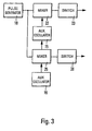
- Fig. 3 represents a further alternative embodiment, which enables the ECCM provision described in this patent specification to be applied simultaneously with the well-known side-lobe suppression and side-lobe blanking.
- a shifted radar transmitter steering pulse is generated for auxiliary transmitter 8 via switch element 23 by means of mixer 22 and auxiliary oscillator 15 and a shifted radar transmitter pulse is generated for auxiliary transmitter 13 via switch element 26 by means of mixer 25 and auxiliary oscillator 16.
- the auxiliary oscillators may be quickly tunable or switchable types of oscillators for generating one transmitter steering pulse having a diverging frequency in a burst, as described above.
- Auxiliary receivers 6 and 11 receive a local oscillator signal that is not shifted, as a result of which the side-lobe suppression and side-lobe blanking remain working. Reactions from jammers to transmitter steering pulses, for example transmitted by auxiliary antenna 5, cannot be processed by auxiliary receiver 6 any longer.
Landscapes
- Engineering & Computer Science (AREA)
- Radar, Positioning & Navigation (AREA)
- Remote Sensing (AREA)
- Computer Networks & Wireless Communication (AREA)
- Physics & Mathematics (AREA)
- General Physics & Mathematics (AREA)
- Radar Systems Or Details Thereof (AREA)
Description
- The invention relates to a radar apparatus comprising at least one directional main antenna, steering means for generating radar transmitter steering pulses to be supplied to the main antenna via transmitter means and for generating auxiliary transmitter steering pulses to be supplied to at least one auxiliary antenna via at least one auxiliary receiver, and receiver means connected to the main antenna.
- A radar apparatus of this kind is known from US-A-4,435,710. The known radar apparatus uses the auxiliary antenna for transmitting auxiliary transmitter pulses during and inbetween transmitter pulses for confuzing jammers. The auxiliary transmitter steering pulses that are transmitted inbetween transmitter pulses are given an RF frequency that differs from the transmitter pulses in order to enable the reception of radar echoes during the transmission of auxiliary transmitter pulses.
- A disadvantage of this known radar apparatus is that in modern radars the dynamic range is so huge that the transmission of auxiliary transmitter pulses prevents the radar from functioning properly. Especially small, stealthy targets will be completely eclipsed by auxiliary transmitter pulses, whatever the RF frequency difference may be.
- Moreover modern radars are preferably equipped with passive ECCM features like side-lobe blanking units, known for example from EP-B 0.173.360 or sidelobe cancellers, known for example from EP-A 0.076.536, which also utilize auxiliary antennas. These passive EECM features are not compatible with the known active ECCM features.
- The radar apparatus according to the invention has the active ECCM features known from US-A 4,435,710 without the disadvantage of eclipsing the reception of echoes of small targets. Moreover the auxiliary antennas are available between radar transmitter pulses and may be used for passive ECCM features. It is characterized in that at least one auxiliary receiver is provided, connected to the at least one auxiliary antenna, the output of the at least one auxiliary receiver being connected to the receiver means for reducing the effect of jammers on the receiver means and that the steering means are designed for generating the auxiliary transmitter steering pulses substantially simultaneously with the radar transmitter steering pulses, the auxiliary transmitter steering pulses deviating from radar transmitter steering pulses.
- The radar apparatus according to invention proves to be most effective against the more intelligent repeater jammers, particularly if these receive the transmitter pulses emitted via the auxiliary antennas stronger than radar transmitter pulses emitted by the main antenna, while residual jammer signals entering the directional main antenna may be cancelled or blanked via corresponding signals received via the auxiliary antennas.
- This object of this invention is solved by a radar apparatus comprising:
- at least one directional main antenna (1),
- steering means (9) for generating radar transmitter steering pulses to be supplied to the main antenna (1) via transmitter means (3), and for generating auxiliary transmitter steering pulses, differing in frequency from the radar transmitter steering pulses, to be supplied to at least one auxiliary antenna (5,10) via at least one auxiliary transmitter (8,13), these steering means (9) are designed for generating the auxiliary transmitter steering pulses substantially simultaneously with the radar transmitter steering pulses
- and receiver means (4) connected to the main antenna (1),
- and at least one auxiliary receiver (6,11) is provided, connected to at least one auxiliary antenna (5,10) and tuned to a frequency of the auxiliary transmitter steering pulses, the output of the at least one auxiliary receiver (6,11) being connected to the receiver means (4) for reducing the effect of jammers on the receiver means (4) during the reception of echoes of the transmitted radar transmitter steering pulses.
- A first embodiment is obtained if the steering means are designed for the generation of auxiliary transmitter steering pulses whose frequency deviate from the radar transmitter steering pulse frequency. This implies that the jammer is required to spread the available transmitting power over a larger frequency range. The steering means can then be designed such that auxiliary transmitter steering pulses are generated whose type of modulation at least substantially corresponds to the type of modulation of the radar transmitter pulses, which has a cost-reducing effect. To this end, the steering means can comprise at least one auxiliary oscillator and at least one mixer for generating frequency-shifted radar auxiliary transmitter steering pulses for the at least one auxiliary antenna. It may then be relevant to select a mixer type that suppresses the original radar transmitter pulses at its output and only passes the frequency-shifted pulses, or in case of an image rejection mixer well-known in the art being used, passes the pulse.
- Another possibility is to use a plurality of auxiliary oscillators, having different frequencies in a range of for instance 20-200 Mc/s, each oscillator being provided with a mixer that generates auxiliary transmitter steering pulses at a corresponding frequency shift. These auxiliary transmitter steering pulses may then, via one or more auxiliary transmitters, be applied to one or more auxiliary antennas. This will cause more confusion to the jammer and will reduce the probability of effectively jamming the radar apparatus, since the transmission power available for jamming will have to be spread over a yet larger frequency range.
- An advanced repeater jammer is generally capable of receiving, amplifying and retransmitting simultaneously a signal received via a side lobe of the main antenna and via a main lobe of the auxiliary antenna. Retransmission is usually effected at a strength that is proportional to the strength of the signal received. A further favourable embodiment of the invention is therefore characterised in that the at least one auxiliary antenna is designed for generating, during emission of the auxiliary transmitter pulses, an auxiliary antenna main lobe which is at least substantially stronger than the main antenna sidelobes. In general, an auxiliary antenna can be dimensioned such that at the horizon, where the jammers are mostly situated, the auxiliary transmitter pulses received are stronger by 10-20 dB than the radar transmitter pulses received via the main antenna sidelobes. A further improvement can be obtained by using for instance four auxiliary antennas, each of which covers an at least partially different space angle. Thus, by accepting a certain measure of directivity, a 6 dB improvement can be obtained in the ratio between said received signal strengths.
- The radar apparatus thus obtained is exceptionally suitable for examining jamming pulses generated by repeater jammers.
- A jamming pulse is usually a replica of an auxiliary transmitter pulse and the accuracy of the replica may provide useful information about the jammer's identity. The radar apparatus is then characterised in that identification means have been provided, connected to the at least one auxiliary receiver, for analyzing jammer-generated responses to transmitted radar pulses. By tuning an available auxiliary receiver to the auxiliary transmitter pulse that has been shifted in frequency as compared with the radar transmitter pulse, interference with echoes produced by the radar transmitter pulse is avoided. To this end, a local oscillator signal, shifted by an auxiliary oscillator may advantageously be used for the auxiliary receiver.
- A further, exceptionally favourable embodiment of the radar apparatus according to the invention is characterised in that the identification means are designed for controlling the steering means. In its simplest form, this controlling entails a command for modification of at least one auxiliary transmitter pulse. This way, it is possible to test the jammer's intelligence and to verify whether the repeater jammer repeats per pulse or uses the same replica. If the steering means are for instance designed for the burst-wise generation of identical radar transmitter pulses, the command may entail the modification of an auxiliary transmitter steering pulse within a burst. This may be useful against certain types of jammers whose design is based on the principle that the radar apparatus to be jammed transmits bursts of for
instance 16 pulses. The operating method of this type of jammer will then be such that upon reception of the first out of a burst of 16 pulses, this first received pulse serves as the replica. Upon the next received pulse, the PRF is calculated on the basis of the time difference. On the basis of this calculated PRF and the available replica, the jammer will then retransmit a burst of 16 replica pulses, if required after a certain phase shift or time delay, for instance for applying range gate stealing. The radar apparatus can now be arranged such that at random moments a modification of one or several auxiliary transmitter pulses in the series of 16 pulses occurs. If the auxiliary antenna nevertheless receives a burst of 16 pulses, this yields more information on the type of jammer. - An advantageous embodiment of the invention is characterised in that the modification of an auxiliary transmitter pulse comprises the omission of the auxiliary transmitter pulse. A further favourable embodiment is characterised in that the modification of a auxiliary transmitter pulse comprises a frequency shift of the transmitter pulse.A further favourable embodiment of the radar apparatus is characterised in that the identification means comprise a database of known jammers, comparison means for comparing the received jammer signal with the jammer signals contained in the database and selection means for selecting commands for the steering signals. This way, the identity of a jammer can be passively ascertained, after which any further information on the jammer can be obtained in an interactive phase.
- The radar apparatus according to the invention will now be described with reference to the following figures, of which:
- Fig. 1
- represents a radar apparatus with ECCM facilities according to the invention;
- Fig. 2
- represents a possible embodiment of the control means incorporated in the radar apparatus according to the invention;
- Fig. 3
- represents an alternative embodiment of the control means.
- Fig. 1 shows a block diagram of a possible embodiment of a radar apparatus according to the invention. As usual in the art, main antenna 1 is connected to transmitter means 3 and receiver means 4 via T/
R device 2, for instance a circulator. Main antenna 1 can for instance be a rotary search antenna, or an active phased array antenna, in which case the T/R device 2, transmitter means 3 and receiver means 4 are an integral part of the array of modules constituting the actual main antenna 1. Fig. 1 auxiliaryly shows auxiliary antenna 5 which is connected to anauxiliary receiver 6 for applying signals received via auxiliary antenna 5 to receiver means 4. Auxiliary antenna 5 is usually of the omnidirectional or semi-omnidirectional type, although it may also show a certain measure of directivity. It is important for auxiliary antenna 5, at least in the space angle in which it will be effective, to have an antenna gain exceeding that of the side lobes of main antenna 1. Only then will it be possible to realize ECCM measures well-known in the art such as side-lobe suppression or side-lobe blanking. Novel is T/R device 7 to which is connectedauxiliary transmitter 8. According to the inventive thought underlying the invention, auxiliary antenna 5 is used for the emission of pulses which, although resembling radar transmitter pulses emitted by main antenna 1, are divergent in one way or another. A jammer, for instance a repeater jammer will use this divergent transmitter pulse, which is nearly always received stronger than the actual radar transmitter pulse to generate a pulse which is aimed at jamming the radar apparatus. By designing receiver means 4 such that the divergent pulses are blocked, the effect of the jammer may be reduced. - Transmitter pulses emitted by auxiliary antenna 5 may differ from radar transmitter pulses by a divergent modulation, for instance by applying an upchirp in case of radar transmitter pulses provided with a downchirp, or by a different timing or frequency. The last mentioned solution requires the least hardware and has the added advantage that the simultaneous emission of the transmitter pulse and the radar transmitter pulse increase the jammer's confusion. Such a steering pulse for
auxiliary transmitter 8 can simply be derived from a radar transmitter steering pulse for transmitter means 3, as generated by steering means 9. - Fig. 1 auxiliaryly represents
auxiliary antenna 10,auxiliary receiver 11, T/R device 12 and auxiliary transmitter 13, which are also capable of generating divergent transmitter pulses, whereby the frequency of these transmitter pulses mostly will deviate from the transmitter pulses emitted by auxiliary antenna 5. This will add to the jammer's confusion. Auxiliary antenna 5 andauxiliary antenna 10 may cover the same space angle, as a result of which the jammer does receive two divergent pulses per radar transmitter pulse, but they may also comprise different space angles. In the latter case, the overall space angle to be covered can be divided into for instance N partially overlapping space subangles, each of which is covered by an auxiliary antenna. This then requires N auxiliary antennas and N auxiliary transmitters, but the gain of these auxiliary antennas may be considerably higher than the gain of an omnidirectional antenna, thus causing an increase of the effective radiated power of the divergent pulses. This will make it more difficult for the jammer to adversely affect radar operation. - In Fig. 1 the receiver means 4 obtain, as usual, a local oscillator signal from steering means 9.
Auxiliary receiver 6 receives a divergent local oscillator signal that has been selected such thatauxiliary receiver 6 is tuned to the frequency of the transmitter pulses emitted by auxiliary antenna 5. The output signal ofauxiliary receiver 6 can subsequently be applied to identification means 14, by means of which the reaction of a jammer on transmitter pulses emitted by auxiliary antenna 5 can be analysed. It may be checked for instance how a certain modulation from such as a frequency chirp is imitated and how a burst of forinstance 16 pulses is repeated. An analysis thus effected mostly enables the jammer's identity to be established. This analysis often requires the use of a database in which the distinctive characteristics of well-known jammers are stored. Similarly,auxiliary antenna 10 andauxiliary receiver 11 can also be used to obtain information concerning the jammer's identity. - When the radar apparatus, as is customary with state-of-the-art doppler radar apparatuses, emits radar transmitter pulses per burst of for
instance 16 identical pulses, it is according to the invention possible to extract more information from the jammer. To this end it is possible to use the identification means 14 to control the steering means 9 in such a way that one or several transmitter steering pulses are modified per burst without causing a modification of the radar transmitter steering pulses. An obvious modification entails the omission of a single transmitter steering pulse. The jammer thus illuminated via an auxiliary antenna may then fill in the missing pulse or not. An auxiliary obvious modification relates to the frequency change of a single transmitter steering pulse, which also offers the possibility to check the jammer's reaction. The way in which the jammer reacts may further contribute to its identification. - Fig. 2 shows a possible embodiment of the steering means of the radar apparatus according to the invention, which comprises three
auxiliary oscillators steering pulse generator 18 can be shifted in frequency for theauxiliary transmitters 8, 13 and on the basis of which the local oscillator signal generated bylocal oscillator 19 for the receiver means 4 can be shifted for theauxiliary receivers auxiliary oscillators selector 20 which selects the auxiliary oscillator signal forauxiliary transmitter 8 andauxiliary receiver 6 and toselector 21 which selects the auxiliary oscillator signal for auxiliary transmitter 13 andauxiliary receiver 11. The auxiliary oscillator signal selected byselector 20 is, along with the radar transmitter steering pulse, applied tomixer 22. The resulting frequency-shifted radar transmitter steering pulse is then supplied toauxiliary transmitter 8 viaswitch element 23. Likewise, the auxiliary oscillator signal selected byselector 21 is, along with the radar transmitter steering pulse, applied tomixer 25 and the frequency-shifted radar transmitter steering pulse is supplied to auxiliary transmitter 13 viaswitch element 26. In addition, the auxiliary oscillator signals selected byselectors mixers auxiliary receivers switch elements 28 and 29 which also receive a non-shifted local oscillator signal. In this way it is possible to apply, as desired, a non-shifted or a shifted local oscillator signal to theauxiliary receivers switch element selectors elements Mixers - An alternative embodiment enables the combination of
mixers mixers - Fig. 3 represents a further alternative embodiment, which enables the ECCM provision described in this patent specification to be applied simultaneously with the well-known side-lobe suppression and side-lobe blanking. In this embodiment, a shifted radar transmitter steering pulse is generated for
auxiliary transmitter 8 viaswitch element 23 by means ofmixer 22 andauxiliary oscillator 15 and a shifted radar transmitter pulse is generated for auxiliary transmitter 13 viaswitch element 26 by means ofmixer 25 andauxiliary oscillator 16. The auxiliary oscillators may be quickly tunable or switchable types of oscillators for generating one transmitter steering pulse having a diverging frequency in a burst, as described above.Auxiliary receivers auxiliary receiver 6 any longer. This requires two auxiliary auxiliary receivers, tuned to the radar transmitter steering pulses shifted by means ofauxiliary oscillators auxiliary receivers
Claims (12)
- Radar apparatus comprising:characterised in thatat least one directional main antenna (1),steering means (9) for generating radar transmitter steering pulses to be supplied to the main antenna (1) via transmitter means (3), and for generating auxiliary transmitter steering pulses, differing in frequency from the radar transmitter steering pulses, to be supplied to at least one auxiliary antenna (5,10) via at least one auxiliary transmitter (8,13),and receiver means (4) connected to the main antenna (1) ,the steering means (9) are designed for generating the auxiliary transmitter steering pulses substantially simultaneously with the radar transmitter steering pulsesand that at least one auxiliary receiver (6,11) is provided, connected to at least one auxiliary antenna (5,10) and tuned to a frequency of the auxiliary transmitter steering pulses, the output of the at least one auxiliary receiver (6,11) being connected to the receiver means (4) for reducing the effect of jammers on the receiver means (4) during the reception of echoes of the transmitted radar transmitter steering pulses.
- Radar apparatus as claimed in claim 1, characterised in that the steering means (9) are designed for the generation of auxiliary transmitter steering pulses whose frequency deviate from the frequency of the radar transmitter steering pulses.
- Radar apparatus as claimed in claim 2, characterised in that the steering means (9) are designed for the generation of auxiliary transmitter steering pulses whose type of modulation at least substantially corresponds to the type of modulation of the radar transmitter steering pulses.
- Radar apparatus as claimed in claim 3, characterised in that the steering means (9) comprise at least one auxiliary oscillator (15,16,17) and at least one mixer (22) for generating frequency-shifted radar transmitter steering pulses for the at least one auxiliary antenna (5,10).
- Radar apparatus as claimed in claim 1 in which the main antenna (1), in addition to an antenna main lobe, also generates antenna side lobes during the emission of radar transmitter pulses, characterised in that the at least one auxiliary antenna (5,10) is designed for generating, during the emission of transmitter pulses, an auxiliary antenna main lobe which is at least substantially stronger than the main antenna side lobes.
- Radar apparatus as claimed in claim 1, characterised in that the apparatus is provided with identification means (14) connected to the at least one auxiliary receiver (6,11), for analyzing jammer-generated responses to emitted transmitter pulses.
- Radar apparatus as claimed in claim 6, characterised in that the identification means (14) are designed for controlling the steering means (9).
- Radar apparatus as claimed in claim 7, characterised in that the controlling entails a command for modification of at least one transmitter steering pulse.
- Radar apparatus as claimed in claim 8, the steering means (9) being designed for the burst-wise generation of identical radar transmitter steering pulses, characterised in that the command entails the modification of one transmitter steering pulse within a burst.
- Radar apparatus as claimed in claim 9, characterised in that the modification comprises the omission of the transmitter steering pulse concerned.
- Radar apparatus as claimed in claim 9, characterised in that the modification comprises the frequency shift of the transmitter steering pulse concerned.
- Radar apparatus as claimed in claim 9, characterised in that the identification means (14) comprise a database of known jammer signals, comparison means for comparing the received jammer signal with the jammer signals contained in the database, and selection means for selecting commands for the steering means.
Applications Claiming Priority (2)
| Application Number | Priority Date | Filing Date | Title |
|---|---|---|---|
| NL9302002 | 1993-11-19 | ||
| NL9302002A NL9302002A (en) | 1993-11-19 | 1993-11-19 | Radar device equipped with ECCM facilities. |
Publications (2)
| Publication Number | Publication Date |
|---|---|
| EP0654678A1 EP0654678A1 (en) | 1995-05-24 |
| EP0654678B1 true EP0654678B1 (en) | 2004-05-12 |
Family
ID=19863154
Family Applications (1)
| Application Number | Title | Priority Date | Filing Date |
|---|---|---|---|
| EP94203267A Expired - Lifetime EP0654678B1 (en) | 1993-11-19 | 1994-11-09 | Radar apparatus provided with ECCM facilities |
Country Status (6)
| Country | Link |
|---|---|
| US (1) | US5539407A (en) |
| EP (1) | EP0654678B1 (en) |
| CA (1) | CA2135551C (en) |
| DE (1) | DE69433772T2 (en) |
| ES (1) | ES2220908T3 (en) |
| NL (1) | NL9302002A (en) |
Families Citing this family (12)
| Publication number | Priority date | Publication date | Assignee | Title |
|---|---|---|---|---|
| NL9400973A (en) * | 1994-06-15 | 1996-01-02 | Hollandse Signaalapparaten Bv | Radar device. |
| NL9401157A (en) * | 1994-07-13 | 1996-02-01 | Hollandse Signaalapparaten Bv | Radar device. |
| NL9401297A (en) * | 1994-08-10 | 1996-03-01 | Hollandse Signaalapparaten Bv | Radar device. |
| WO2000052497A2 (en) * | 1999-02-16 | 2000-09-08 | Raytheon Company | Radar system having spoofer, blanker and canceler |
| US6304214B1 (en) * | 1999-05-07 | 2001-10-16 | Lucent Technologies Inc. | Antenna array system having coherent and noncoherent reception characteristics |
| FR2888332B1 (en) * | 2005-07-08 | 2007-11-02 | Thales Sa | BISTATIC RADIOELECTRIC DEVICE FOR REALIZING AN INSTRUCTION DETECTION BARRIER |
| EP2048800A1 (en) * | 2007-10-10 | 2009-04-15 | Semiconductor Ideas to The Market (ItoM) BV | Anti jamming system |
| EP2048775A1 (en) * | 2007-10-10 | 2009-04-15 | Semiconductors Ideas to the Market (ITOM) B.V. | Anti jamming system |
| DE102007050196A1 (en) * | 2007-10-20 | 2009-04-23 | Selex Sistemi Integrati Gmbh | Weather radar |
| FR2987453B1 (en) * | 2012-02-24 | 2014-04-25 | Thales Sa | RADAR LOCATION SYSTEM AND METHOD |
| IL282412B2 (en) * | 2018-10-25 | 2024-01-01 | Saab Ab | Radar system for jammed environments |
| CN115236607B (en) * | 2022-06-30 | 2024-06-04 | 北京邮电大学 | Radar anti-interference strategy optimization method based on double-layer Q learning |
Citations (1)
| Publication number | Priority date | Publication date | Assignee | Title |
|---|---|---|---|---|
| EP0173360A1 (en) * | 1984-08-21 | 1986-03-05 | Hollandse Signaalapparaten B.V. | Radar system comprising side-lobe blanking circuit |
Family Cites Families (8)
| Publication number | Priority date | Publication date | Assignee | Title |
|---|---|---|---|---|
| US4010469A (en) * | 1951-06-20 | 1977-03-01 | The Rand Corporation | Interference suppression |
| US4044359A (en) * | 1962-01-09 | 1977-08-23 | General Electric Company | Multiple intermediate frequency side-lobe canceller |
| US5162805A (en) * | 1975-02-19 | 1992-11-10 | The United States Of America As Represented By The Secretary Of The Navy | Frequency diversity sidelobe canceller |
| DE3028225C1 (en) * | 1980-07-25 | 1992-09-17 | Siemens Ag | Radar receiver |
| US4435710A (en) * | 1981-03-31 | 1984-03-06 | Westinghouse Electric Corp. | System for obscuring antenna sidelobe signals |
| FR2632419B1 (en) * | 1983-11-08 | 1990-10-19 | Thomson Csf | ANTI-JAMMING METHOD AND DEVICE FOR RADAR AND RADAR EQUIPPED WITH SUCH A DEVICE |
| NL8802863A (en) * | 1988-11-21 | 1990-06-18 | Hollandse Signaalapparaten Bv | RADAR DEVICE AND SIDE LOOP SUPPRESSION UNIT SUITABLE FOR USE IN SUCH A RADAR DEVICE. |
| JPH03148081A (en) * | 1989-11-06 | 1991-06-24 | Mitsubishi Electric Corp | Radar equipment |
-
1993
- 1993-11-19 NL NL9302002A patent/NL9302002A/en not_active Application Discontinuation
-
1994
- 1994-11-08 US US08/337,499 patent/US5539407A/en not_active Expired - Lifetime
- 1994-11-09 EP EP94203267A patent/EP0654678B1/en not_active Expired - Lifetime
- 1994-11-09 DE DE69433772T patent/DE69433772T2/en not_active Expired - Lifetime
- 1994-11-09 ES ES94203267T patent/ES2220908T3/en not_active Expired - Lifetime
- 1994-11-10 CA CA002135551A patent/CA2135551C/en not_active Expired - Lifetime
Patent Citations (1)
| Publication number | Priority date | Publication date | Assignee | Title |
|---|---|---|---|---|
| EP0173360A1 (en) * | 1984-08-21 | 1986-03-05 | Hollandse Signaalapparaten B.V. | Radar system comprising side-lobe blanking circuit |
Also Published As
| Publication number | Publication date |
|---|---|
| ES2220908T3 (en) | 2004-12-16 |
| CA2135551A1 (en) | 1995-05-20 |
| CA2135551C (en) | 2005-01-11 |
| EP0654678A1 (en) | 1995-05-24 |
| US5539407A (en) | 1996-07-23 |
| DE69433772T2 (en) | 2005-05-19 |
| DE69433772D1 (en) | 2004-06-17 |
| NL9302002A (en) | 1995-06-16 |
Similar Documents
| Publication | Publication Date | Title |
|---|---|---|
| US7639171B2 (en) | Radar system and method of digital beamforming | |
| JP2545958B2 (en) | Digital beamforming radar | |
| US6288672B1 (en) | Holographic radar | |
| US7737879B2 (en) | Split aperture array for increased short range target coverage | |
| EP0654678B1 (en) | Radar apparatus provided with ECCM facilities | |
| US6940447B2 (en) | Radar device and method for operating a radar device | |
| JP2567332B2 (en) | Time division radar system | |
| JP3393204B2 (en) | Multi-beam radar device | |
| US8203479B2 (en) | Electronic counter measure system | |
| EP1159635B1 (en) | Radar system having spoofer, blanker and canceler | |
| JPH075252A (en) | Time-sharing type fm radar system | |
| WO2007014333A2 (en) | Methods and apparatus for automotive radar sensors | |
| Grant et al. | Introduction to electronic warfare | |
| US5506582A (en) | Signal processing apparatus | |
| US4496949A (en) | MTI Radar adaptable to different environmental conditions | |
| US7151476B2 (en) | Radar system having a beamless emission signature | |
| US4435710A (en) | System for obscuring antenna sidelobe signals | |
| IE53597B1 (en) | Navigation system | |
| Ahmed et al. | Experimental study on multi-channel waveform agile beamforming and testbed calibration | |
| CN114185006B (en) | Time diversity deception jamming suppression method based on pulse coding | |
| JPH08262133A (en) | Time-sharing radar system | |
| JPH06186321A (en) | Multi-beam radar device | |
| JP2605957B2 (en) | Airborne radar equipment | |
| van Rossum et al. | Space-Time Block Coding waveform for suppression of jamming in a MIMO radar | |
| JPS5883285A (en) | Radar device |
Legal Events
| Date | Code | Title | Description |
|---|---|---|---|
| PUAI | Public reference made under article 153(3) epc to a published international application that has entered the european phase |
Free format text: ORIGINAL CODE: 0009012 |
|
| AK | Designated contracting states |
Kind code of ref document: A1 Designated state(s): DE ES FR GB NL |
|
| 17P | Request for examination filed |
Effective date: 19951124 |
|
| 17Q | First examination report despatched |
Effective date: 19961108 |
|
| RAP1 | Party data changed (applicant data changed or rights of an application transferred) |
Owner name: THALES NEDERLAND B.V. |
|
| GRAP | Despatch of communication of intention to grant a patent |
Free format text: ORIGINAL CODE: EPIDOSNIGR1 |
|
| GRAS | Grant fee paid |
Free format text: ORIGINAL CODE: EPIDOSNIGR3 |
|
| GRAA | (expected) grant |
Free format text: ORIGINAL CODE: 0009210 |
|
| AK | Designated contracting states |
Kind code of ref document: B1 Designated state(s): DE ES FR GB NL |
|
| REG | Reference to a national code |
Ref country code: GB Ref legal event code: FG4D |
|
| REF | Corresponds to: |
Ref document number: 69433772 Country of ref document: DE Date of ref document: 20040617 Kind code of ref document: P |
|
| REG | Reference to a national code |
Ref country code: ES Ref legal event code: FG2A Ref document number: 2220908 Country of ref document: ES Kind code of ref document: T3 |
|
| ET | Fr: translation filed | ||
| PLBE | No opposition filed within time limit |
Free format text: ORIGINAL CODE: 0009261 |
|
| STAA | Information on the status of an ep patent application or granted ep patent |
Free format text: STATUS: NO OPPOSITION FILED WITHIN TIME LIMIT |
|
| 26N | No opposition filed |
Effective date: 20050215 |
|
| PGFP | Annual fee paid to national office [announced via postgrant information from national office to epo] |
Ref country code: FR Payment date: 20131108 Year of fee payment: 20 Ref country code: GB Payment date: 20131106 Year of fee payment: 20 Ref country code: DE Payment date: 20131106 Year of fee payment: 20 |
|
| PGFP | Annual fee paid to national office [announced via postgrant information from national office to epo] |
Ref country code: ES Payment date: 20131029 Year of fee payment: 20 Ref country code: NL Payment date: 20131109 Year of fee payment: 20 |
|
| REG | Reference to a national code |
Ref country code: DE Ref legal event code: R071 Ref document number: 69433772 Country of ref document: DE |
|
| REG | Reference to a national code |
Ref country code: NL Ref legal event code: V4 Effective date: 20141109 |
|
| REG | Reference to a national code |
Ref country code: GB Ref legal event code: PE20 Expiry date: 20141108 |
|
| PG25 | Lapsed in a contracting state [announced via postgrant information from national office to epo] |
Ref country code: GB Free format text: LAPSE BECAUSE OF EXPIRATION OF PROTECTION Effective date: 20141108 |
|
| REG | Reference to a national code |
Ref country code: ES Ref legal event code: FD2A Effective date: 20150826 |
|
| PG25 | Lapsed in a contracting state [announced via postgrant information from national office to epo] |
Ref country code: ES Free format text: LAPSE BECAUSE OF EXPIRATION OF PROTECTION Effective date: 20141110 |