EP1159635B1 - Radar system having spoofer, blanker and canceler - Google Patents
Radar system having spoofer, blanker and canceler Download PDFInfo
- Publication number
- EP1159635B1 EP1159635B1 EP00939273A EP00939273A EP1159635B1 EP 1159635 B1 EP1159635 B1 EP 1159635B1 EP 00939273 A EP00939273 A EP 00939273A EP 00939273 A EP00939273 A EP 00939273A EP 1159635 B1 EP1159635 B1 EP 1159635B1
- Authority
- EP
- European Patent Office
- Prior art keywords
- blanker
- beam pattern
- radar
- antenna
- sidelobe
- Prior art date
- Legal status (The legal status is an assumption and is not a legal conclusion. Google has not performed a legal analysis and makes no representation as to the accuracy of the status listed.)
- Expired - Lifetime
Links
Images


Classifications
-
- H—ELECTRICITY
- H01—ELECTRIC ELEMENTS
- H01Q—ANTENNAS, i.e. RADIO AERIALS
- H01Q3/00—Arrangements for changing or varying the orientation or the shape of the directional pattern of the waves radiated from an antenna or antenna system
- H01Q3/26—Arrangements for changing or varying the orientation or the shape of the directional pattern of the waves radiated from an antenna or antenna system varying the relative phase or relative amplitude of energisation between two or more active radiating elements; varying the distribution of energy across a radiating aperture
- H01Q3/2605—Array of radiating elements provided with a feedback control over the element weights, e.g. adaptive arrays
- H01Q3/2611—Means for null steering; Adaptive interference nulling
- H01Q3/2629—Combination of a main antenna unit with an auxiliary antenna unit
-
- G—PHYSICS
- G01—MEASURING; TESTING
- G01S—RADIO DIRECTION-FINDING; RADIO NAVIGATION; DETERMINING DISTANCE OR VELOCITY BY USE OF RADIO WAVES; LOCATING OR PRESENCE-DETECTING BY USE OF THE REFLECTION OR RERADIATION OF RADIO WAVES; ANALOGOUS ARRANGEMENTS USING OTHER WAVES
- G01S7/00—Details of systems according to groups G01S13/00, G01S15/00, G01S17/00
- G01S7/02—Details of systems according to groups G01S13/00, G01S15/00, G01S17/00 of systems according to group G01S13/00
- G01S7/28—Details of pulse systems
- G01S7/2813—Means providing a modification of the radiation pattern for cancelling noise, clutter or interfering signals, e.g. side lobe suppression, side lobe blanking, null-steering arrays
-
- G—PHYSICS
- G01—MEASURING; TESTING
- G01S—RADIO DIRECTION-FINDING; RADIO NAVIGATION; DETERMINING DISTANCE OR VELOCITY BY USE OF RADIO WAVES; LOCATING OR PRESENCE-DETECTING BY USE OF THE REFLECTION OR RERADIATION OF RADIO WAVES; ANALOGOUS ARRANGEMENTS USING OTHER WAVES
- G01S7/00—Details of systems according to groups G01S13/00, G01S15/00, G01S17/00
- G01S7/02—Details of systems according to groups G01S13/00, G01S15/00, G01S17/00 of systems according to group G01S13/00
- G01S7/36—Means for anti-jamming, e.g. ECCM, i.e. electronic counter-counter measures
-
- H—ELECTRICITY
- H01—ELECTRIC ELEMENTS
- H01Q—ANTENNAS, i.e. RADIO AERIALS
- H01Q1/00—Details of, or arrangements associated with, antennas
- H01Q1/52—Means for reducing coupling between antennas; Means for reducing coupling between an antenna and another structure
- H01Q1/521—Means for reducing coupling between antennas; Means for reducing coupling between an antenna and another structure reducing the coupling between adjacent antennas
- H01Q1/525—Means for reducing coupling between antennas; Means for reducing coupling between an antenna and another structure reducing the coupling between adjacent antennas between emitting and receiving antennas
-
- H—ELECTRICITY
- H01—ELECTRIC ELEMENTS
- H01Q—ANTENNAS, i.e. RADIO AERIALS
- H01Q3/00—Arrangements for changing or varying the orientation or the shape of the directional pattern of the waves radiated from an antenna or antenna system
- H01Q3/26—Arrangements for changing or varying the orientation or the shape of the directional pattern of the waves radiated from an antenna or antenna system varying the relative phase or relative amplitude of energisation between two or more active radiating elements; varying the distribution of energy across a radiating aperture
- H01Q3/2605—Array of radiating elements provided with a feedback control over the element weights, e.g. adaptive arrays
- H01Q3/2611—Means for null steering; Adaptive interference nulling
-
- H—ELECTRICITY
- H04—ELECTRIC COMMUNICATION TECHNIQUE
- H04K—SECRET COMMUNICATION; JAMMING OF COMMUNICATION
- H04K3/00—Jamming of communication; Counter-measures
- H04K3/20—Countermeasures against jamming
- H04K3/22—Countermeasures against jamming including jamming detection and monitoring
- H04K3/224—Countermeasures against jamming including jamming detection and monitoring with countermeasures at transmission and/or reception of the jammed signal, e.g. stopping operation of transmitter or receiver, nulling or enhancing transmitted power in direction of or at frequency of jammer
- H04K3/228—Elimination in the received signal of jamming or of data corrupted by jamming
-
- H—ELECTRICITY
- H04—ELECTRIC COMMUNICATION TECHNIQUE
- H04K—SECRET COMMUNICATION; JAMMING OF COMMUNICATION
- H04K3/00—Jamming of communication; Counter-measures
- H04K3/20—Countermeasures against jamming
- H04K3/28—Countermeasures against jamming with jamming and anti-jamming mechanisms both included in a same device or system, e.g. wherein anti-jamming includes prevention of undesired self-jamming resulting from jamming
-
- H—ELECTRICITY
- H04—ELECTRIC COMMUNICATION TECHNIQUE
- H04K—SECRET COMMUNICATION; JAMMING OF COMMUNICATION
- H04K3/00—Jamming of communication; Counter-measures
- H04K3/60—Jamming involving special techniques
- H04K3/65—Jamming involving special techniques using deceptive jamming or spoofing, e.g. transmission of false signals for premature triggering of RCIED, for forced connection or disconnection to/from a network or for generation of dummy target signal
-
- H—ELECTRICITY
- H04—ELECTRIC COMMUNICATION TECHNIQUE
- H04K—SECRET COMMUNICATION; JAMMING OF COMMUNICATION
- H04K3/00—Jamming of communication; Counter-measures
- H04K3/80—Jamming or countermeasure characterized by its function
- H04K3/82—Jamming or countermeasure characterized by its function related to preventing surveillance, interception or detection
- H04K3/825—Jamming or countermeasure characterized by its function related to preventing surveillance, interception or detection by jamming
-
- H—ELECTRICITY
- H04—ELECTRIC COMMUNICATION TECHNIQUE
- H04K—SECRET COMMUNICATION; JAMMING OF COMMUNICATION
- H04K2203/00—Jamming of communication; Countermeasures
- H04K2203/30—Jamming or countermeasure characterized by the infrastructure components
- H04K2203/32—Jamming or countermeasure characterized by the infrastructure components including a particular configuration of antennas
Definitions
- the invention relates to a radar system of the kind comprising a plurality of antennas including a main antenna having a main beam pattern and a blanker antenna having a blanker beam pattern; a beam forming network including the nulling circuit, said beam forming network being coupled to said main antenna for forming a sum beam pattern having a null in the direction of a jammer and to the blanker antenna for forming a blanker beam pattern having a null in the direction of the jammer; means for processing radar signals received in the sum and blanker beam patterns; and a comparison circuit for comparing the level of signals received in said sum beam pattern with the level of signals received in said blanker beam pattern in order to determine when radar signals received in said main beam pattern are representative of a valid target.
- Jamming is used to interfere electronically with an enemy radar system.
- the jammer generates and transmits radar signals which are designed to saturate or otherwise effectively disable the enemy radar receiver.
- Jammers may generate jamming signals based on knowledge of typical radar operating bands of frequencies of the system to be jammed.
- the jammer signal may be transmitted over a limited frequency interval based on knowledge or an estimate of the instantaneous frequency of the jammed radar system (this technique is sometimes referred to as repeater jamming).
- Smart jammers have the capability to determine the frequency of the transmitted radar signals and focus the jamming energy over a narrow band at the determined frequency (this technique is sometimes referred to as spot jamming).
- Another type of jamming is referred to as barrage jamming in which jamming signals are radiated over a wide band of frequencies.
- auxiliary antenna(s) receive and process jammer signals in order to determine weights necessary or the auxiliary antenna outputs to be added to the main beam in order to provide a null in the sidelobes at the jammer direction.
- the auxiliary antennas used for sidelobe cancellation have a relatively wide field of view, as may be provided by an omnidirectional, or isotropic antenna.
- such antennas have relatively low gain such as on the order of 6 dB, requiring significant further gain to be introduced in order to effectively null the sidelobes in the direction of the jammer.
- the introduction of such gain on the auxiliary channels amplifies thermal noise, which couples into the main beam, thereby degrading the sensitivity of the main beam.
- nulling one sidelobe tends to increase sidelobes in other directions.
- the sidelobe canceller can be an effective way of counteracting the effects of sidelobe jamming.
- Blanking is another technique used to reduce the effects of sidelobe interference.
- a blanker utilises a dedicated receive antenna and processing channel, with the signal processing being matched to the main beam processing.
- the gain of the blanking channel is greater than that of the main beam sidelobes.
- the outputs of the main beam processor and the blanker processor are compared in order to determine whether main beam target detections are valid. More particularly, if sidelobe interference is strong, then the signal strength in the blanker channel will be stronger than in the main beam channel and the main beam output is rejected. Alternatively, if the signal strength in the main beam channel is greater than that in the blanker channel, then main beam target detections are considered valid. Interference signals blanked in this manner include strong sidelobe clutter, larger aircraft, repeater jammers, or jammers which radiate radar signals like chirp signals.
- EP 0765482 describes a radar apparatus having a sidelobe blanking circuit.
- a spoofer used to reduce the effectiveness of smart jammers. Smart jammers are capable of listening to a transmitted radar signal to deduce its frequency and then focusing the jamming energy to a fraction of the radar band at the deduced frequency.
- a spoofer includes a waveform generator which generates a spoofer signal capable of confusing a smart sidelobe jammer so as to prevent the jammer from ascertaining the frequency of the actual radar signals. This is, the spoofer signal is selected to camouflage the actual radar signal. This may be achieved in various ways, such as by transmitting a noise-like signal or by transmitting a replica of a radar signal.
- the spoofer signal may be a swept sinewave having an amplitude greater than the amplitude of the actual radar signal over the entire frequency range of operation. While it is desirable that the spoofer antenna be nearly omnidirectional, it is also desirable that the spoofer power be relatively low.
- Spoofers typically utilise a separate transmit antenna spaced from the main transmit antenna. This is because antiradiation missiles can lock on "active decoys" which are radar signals radiated in frequencies surrounding the frequency of the actual radar signal. If the spoofer antenna were integral to the main transmit antenna, its use could cause an antiradiation missile to lock onto the radar system.
- US 4959653 describes a radar system of the kind defined hereinbefore at the beginning in which a steering vector that corresponds to an omnidirectional antenna pattern for blanking is calculated. This vector is premultiplied by the inverse of a covariance matrix. The resulting weights create a blanker channel which is essentially omnidirectional but which has pattern nulls directed towards noise sources specified by the covariance matrix.
- the covariance matrix is composed of the expected products of each antenna signal of an N antenna array, with each of the other antenna signals, the array of N antennas generating an N x N covariance matrix.
- a radar system of the kind defined hereinbefore at the beginning is characterised in that the nulling circuit is an open loop circuit for nulling in the direction of the jammer, the nulling circuit being responsive to the detected jammer direction to provide the null in the sum beam pattern and in the blanker beam pattern; and in that a spoofer is coupled to the blanker antenna, the blanker antenna comprising linear arrays.
- a radar system can operate in the presence of strong sidelobe jamming without the conventional problems attributable to noise amplification.
- the open loop nulling circuit comprises an open loop ECM nulling map circuit for detecting the direction of the jammer.
- the radar system may also include a plurality of auxiliary antennas and a sidelobe canceller coupled to said plurality of auxiliary antennas.
- certain drawbacks of the sidelobe canceller are overcome with the sidelobe canceller providing additional jamming rejection. More specifically, with the open loop nulling, the sidelobe auxiliary antennas will have more gain in the jamming direction than the main beam, rather than less gain as would be the case in absence of open loop nulling in the jammer direction.
- the main beam patterns include a sum beam (beams) and difference channels, such as ⁇ A z , ⁇ E1, and ⁇ . That is, whereas conventional blankers were disabled in the presence of strong jamming in order to prevent excessive noise from being coupled into the main beam, by minimising the sensitivity of the blanker channel to sidelobe jammer signals, the blanker can be kept on in the presence of strong sidelobe jamming.
- the effectiveness of the blanker as to sidelobe interference and barrage jamming is maintained while reducing its sensitivity and thus also the noise associated with blanker operation in the presence of jamming.
- omnidirectional sidelobe canceller antenna(s) can be used without the conventional problems associated with canceller operation in the presence of strong sidelobe jamming. That is, whereas it has heretofore been necessary to introduce significant gain into the canceller channels in order to effectively cancel the sidelobes in the presence of strong jamming, since the sidelobes are already reduced by the open loop nulling in the main and blanker beams, the canceller gain necessary to further reduce the effect of the jamming signals and to cancel the sidelobes is reduced. Stated differently, by introducing nulls into the main and blanker beams, the work of the sidelobe canceller is made easier (i.e., less gain is required), thereby reducing the problems associated with noise amplification. Thus, the effectiveness of the canceller as to sidelobe jamming is maintained, but without the conventional noise problems associated with canceller operation in the presence of sidelobe jamming.
- the radar system uses an antenna including a pair of linear arrays disposed orthogonal with respect to one another as a blanker antenna.
- one of the linear arrays provides full azimuth coverage (i.e., is omnidirectional in azimuth) but limited elevation coverage, such as on the order of 10 degrees.
- the second linear array is omnidirectional in elevation with adaptive gain in azimuth in order to point beams in the direction of the jammers.
- the difference beam generated by subtracting signals received by the second linear array from signals received by the first linear array provides a composite beam that is omnidirectional in azimuth and has nulls in the direction of the jammers.
- the blanker beam has -15dBi nulls in the direction of the jammers and thus, is able to operate even in the presence of strong sidelobe jamming.
- the canceler auxiliary antennas have 21dB more gain in the jamming directions than the blanker beam, instead of 14dB less (for a 20dBi sidelobe in the jammer direction).
- the first linear array provides the blanker antenna on receive and the spoofer antenna on transmit.
- Use of the null(s) in the antenna beam patterns advantageously reduces the power associated with the spoofer, since the power required of the spoofer is less in a -15dBi main beam than for a +20dBi sidelobe. Further, the nulling permits the spoofer antenna to be integral with the main beam aperture without adding significant risk of antiradiation seekers locking onto the spoofer signals.
- a spoofer typically radiates signals in the direction of jammers so that smart sidelobe jammers cannot deduce the radar frequency and spot jam, thereby increasing the jammer ERP by the ratio of barrage jamming bandwidth to the spot jamming bandwidth.
- the spot jamming could be as narrow as the radar search bandwidth, and the ratio of jamming bandwidth to signal bandwidth as high as 30 dB.
- the waveform of a spoofer should contain multiple signals, each with the envelope and phase modulation of the radar signal, and dispersed across the total operating band in the frequency slots or bands assigned to the radar, with the spoofer signal seen by the jammer higher than the radar signal in the sidelobes.
- a blanker channel typically provides the same signal processing matched filter as for the main beam channel. Its input is from an antenna which has more gain than the sidelobes of the main beam in the angle of the region likely to cause interference signals.
- a comparison between channels at the output of the processor rejects detections in the main beam channel if the signal in the sidelobe channel is stronger. Signals blanked in this process include strong sidelobe clutter, larger aircraft, repeater jammers, or jammers which radiate radar like chirp signals.
- a major problem with sidelobe blankers is the inability to achieve adequate gain relative to the main beam sidelobes, so as to minimize noise in the blanker channel from degrading main beam performance. These problems are exacerbated when the sidelobe blanker phase center is displaced from that of the main beam, because multipath reflections can reduce incoming signals in the blanker while increasing them in the main beam.
- auxiliary channel antenna should, like the blanker, have more gain than the main beam sidelobe in the direction of the jammer.
- near omni-directional antennas are used for the auxiliary antennas however the amplification required to provide a strong enough signal has two deleterious effects.
- the noise from the sidelobe canceller (SLC) adds to the main beam, degrading sensitivity and, secondly, sidelobes in other directions increase.
- ECM electronic countermeasures
- phased array radars to date have traditionally combined quadrant symmetric elements or subarrays to form sum E, azimuth ⁇ Az, and elevation ( ⁇ E1) beams. As shown below, there is also a ⁇ output which is shown to be the product of the ⁇ Az and the ⁇ El channels. This fourth channel provides an additional degree of freedom so that the array can null a main beam jammer and still provide normalized azimuth and elevation channels.
- Extending the architecture to include a single main beam jammer means that the number of omni-directional auxiliary elements required for canceling n jammer can be augmented by the ⁇ - ⁇ channel with the ⁇ channel being used to cancel one jammer, whether it is in the sidelobes or in the main beam.
- a spoofer radiates noise-like or radar waveform replica-like signals dispersed across the band.
- a smart jammer can listen to radar signal and jam a fraction of the radar band, increasing J/N by up to 20-30 dB.
- short range radars have long dwells and long range radars have targets beyond jammer range.
- the objective is to have a spoofer signal seen by a smart jammer larger than a signal from radar transmit sidelobes by a ratio of total bandwidth to search signal bandwidth of up to 30dB.
- the sidelobe cancellation requires at least one auxiliary element per jammer.
- SLC auxiliary antenna should cover the field of view of expected jammers, yet have high gain.
- limitations include noise from SLC which adds to the main beam signal and also sidelobes in other directions increase.
- a system concept of operation for a solid state phased array radar includes an ECM map that locates jammers.
- Open loop receive weights using phase/amplitude module settings) place nulls in jammer directions (limited by errors to-15dBi).
- Single element omni element antennas provide 6 dB gain for an auxiliary antenna.
- An antenna for use with the contemplated system includes a vertical linear array to provide a Beam A, the vertical linear array being phased to provide high gain near horizon for high power jammers, but which can be tapered to include moderate gain for higher elevation, lower powered jammers.
- the antenna further includes a horizontal linear array that provides a Beam B, the horizontal linear beam being omni in elevation, but points beams in direction of the jammers.
- a differencing (Beam A minus Beam B) output beam is also provided which has uniform gain in azimuth (for SLB function) and has -15dBi nulls in the jammer directions (for SLC function).
- the beam A also serves as a spoofer beam on transmit.
- Important features of the latter includes minimizing SLC sensitivity loss, reducing multipath effects on blanker and SLC, avoids increasing sidelobes with SLC in other than the jammer direction, preserves simultaneous operation of SLB and SLC functions and provides a low power spoofer capability for defeating smart (DRFM) jammers.
- DRFM smart
- a radar system 10 includes a receiver 14 having a blanker channel 13 and a sidelobe canceler 16 and further includes a transmitter 12 including a spoofer 18.
- the transmitter 12 includes a main channel 20 having a radar waveform generator 22 which generates radar signals in predetermined frequency slots or bands over an operating band, such as the X band, for coupling to a radar signal transmitter 24.
- the transmitter 24 amplifies the radar signals and couples the amplified signals 25 to a radar transmit antenna 26 for transmission of the radar signals in order to detect targets of interest.
- the spoofer 18 includes a spoofer waveform generator 30 for generating spoofer signals capable of diverting or otherwise confusing smart sidelobe jammers from the actual radar signals transmitted by antenna 26.
- the spoofer signals are selected in order to effectively prevent smart sidelobe jammers from ascertaining the frequency of the radar signals 25.
- the spoofer signal has the same envelope as the radar signal 25 but different phase modulation over the entire operating band in the frequency slots or bands assigned to the radar signals 25, with an amplitude greater than the amplitude of the radar signal, at least in the sidelobes.
- the spoofer signal is coupled to a spoofer transmitter 32 for further coupling to, and transmission by a spoofer antenna 34.
- the spoofer signals are radiated in the direction of jammers. It will be appreciated by those of ordinary skill in the art that various transmitter and antenna configurations are possible for use with the transmitter 12 of Figure 1 .
- the receiver 14 includes a receive antenna array 40 having a plurality N main beam subarrays 1 and associated electronics (including, for example, splitters, phase shifters, summing and difference circuits) for forming a sum beam pattern or signal ⁇ 42, an azimuth difference pattern or signal ⁇ Az 44, an elevation difference pattern or signal ⁇ El 46 and an optional difference/difference pattern or signal ⁇ 48. Also provided in the antenna array 40 are a further plurality of n auxiliary antennas 1 provided for use with the sidelobe canceler 16. In the illustrative embodiment, the antenna array 40 is a planar array of solid state modules, having phase and amplitude control.
- the blanker channel 13 includes a discrete blanker antenna 70 which, in the illustrative embodiment is provided in the form of a linear array.
- the signals from the array elements are summed by summer 72 to provide the blanker beam pattern BL or signal 43.
- Each of the beam patterns or signals is coupled to a respective moving target indicator (MTI) circuit 76 for processing.
- MTI circuit includes a filter, such as a delay line filter, designed to reduce the effects of clutter.
- the time domain radar signal provided by the input beam patterns or signals is converted into a frequency domain signal and summed with a predetermined weight (which is a function of either known or modeled clutter frequencies and which are calculated from the estimation of covariance between the sidelobe canceler and other channels) in order to produce notches in the respective bandpass filter associated with each MTI circuit to modify the beam pattern in the passband.
- the resulting signals are then converted back into the time domain at the output of the respective MTI circuit 76.
- each of the n sidelobe canceler auxiliary antenna 1' is likewise coupled to an MTI circuit 76 of the type described above for processing.
- An adaptive weight circuit 80 is responsive to the signals received by the auxiliary antenna and modified by the respective MTI circuit 76 in order to determine a plurality of weights necessary to be introduced to each channel in order to null the sidelobes of the respective pattern.
- the sidelobe canceler 16 provides sidelobe cancellation in the direction of jammers.
- at least one auxiliary antenna per jammer is necessary.
- the auxiliary antennas 1' are omnidirectional antennas.
- a pulse compression circuit 82 Further signal processing in each channel is provided by a pulse compression circuit 82, a Doppler matched filter 84, and a threshold detection circuit 90, as is conventional. Note that the blanker and sum beam channels have identical matched filters.
- the sum beam pattern 42 is shown in relation to the blanker beam pattern 43.
- the sum beam pattern includes a center beam 42a and a plurality of sidelobes 42b.
- the gain of the blanker beam 43 is greater than the gain of the main beam sidelobes 42b.
- comparison of the output of the blanker and main beam channels by a comparison circuit 90 can be used to determine if a main beam detection is valid. More particularly, if detections in the main beam are stronger than detections in the blanker beam, then the main beam detections are determined to be valid (since excessive interference was not detected by the blanker). Alternatively, if detections in the blanker beam are stronger than detections in the main beam, then main beam detections are rejected as invalid due to excessive interference.
- a solid state phased array radar system 100 is shown to include a transmitter 104 and a receiver 106.
- the radar system 100 differs from the radar system 10 of Figure 1 in at least the following significant respects.
- a combined antenna array 120 is used for the blanker and spoofer functions as well as for the main beam and sidelobe canceler functions and, secondly, the radar system 100 includes open loop nulling in the direction of jammers in the main beam and blanker channels.
- the combined antenna array 120 includes a pair of crossed linear arrays, as will be described below in conjunction with Figure 6 .
- the open loop nulling is implemented by an open loop nulling circuit 52 including an ECM mapping circuit 112 and a weight processor 114.
- the antenna array 120 includes a main beam aperture as well as a crossed linear array which is used for the blanker and spoofer functions described below in conjunction with Figure 6 .
- the spoofer transmitter 32 in response to a spoofer waveform generator 30, provides spoofer signals 33 to the antenna array 120 for transmission.
- the antenna array 120 includes electronics (including, for example, splitters, phase shifters, summing and difference circuits) for generating a sum beam pattern ⁇ 60, a blanker beam pattern BL 62, an azimuth difference pattern ⁇ Az 64, an elevation difference pattern ⁇ El 66 and an optional difference/difference pattern ⁇ 68.
- the ECM mapping circuit 112 is operable to map the direction of jammers. This is achieved by scanning the array beam(s) along the region containing jammers and measuring and storing jammer locations. With the jammer direction information provided by the mapping circuit 112, the weight processor 114 calculates a plurality of weights 140 necessary for the antenna 120 to introduce a null in the direction of the jammers by adjusting phase/amplitude antenna module settings. Weights for each beam are calculated using optimum filter weighting theory to produce the desired null.
- Each of the resulting beam patterns thus has nulls in the directions of the jammers and may be referred to as nulled sum beam pattern ⁇ 60, nulled blanker beam pattern BL 62, nulled azimuth difference pattern ⁇ Az 64, nulled elevation difference pattern ⁇ E1 66 and nulled difference/difference pattern ⁇ 68.
- the auxiliary elements 124 are provided by n omnidirectional antenna elements, each of which is coupled to the sidelobe canceler 16. More particularly, each auxiliary element is coupled to a respective MTI circuit 76 of the sidelobe canceler 16, as shown.
- the nulled sum beam pattern 60 is shown having nulls in the two illustrated jammer directions 150, 152 while preserving blanker gain in other directions.
- the sum beam 60 is insensitive to the jamming energy in these directions.
- the nulled blanker beam pattern 62 is shown to have nulls at the same jammer directions 150, 152. With this arrangement, the blanker can be kept operational, even in the presence of strong sidelobe jamming.
- the attenuation (provided digitally in the signal processor) applied to the auxiliary channel will permit cancellation with less than 1 dB noise carryover loss. Also, with open loop nulling, the cancellation required is typically 20 dB less than for conventional systems, making the canceler system less susceptible to phase and amplitude unbalance between main and auxiliary channels.
- the optional ⁇ channel can be used to augment the open loop nulling described above.
- the ⁇ output is the product of the ⁇ Az and ⁇ E1 channels.
- the ⁇ channel can be used as an additional auxiliary channel, to cancel one jammer. More particularly, the ⁇ channel can be used to null either a sidelobe or a mainlobe jammer, and still permit normalized azimuth and elevation channels. This is because a normalized monopulse estimate is obtained from two beams (either ⁇ and ⁇ Az or ⁇ and ⁇ E1), both of which can be pointed at the jammer to null the jammer while producing an off-null target response.
- the modified angle channels ( ⁇ E1', ⁇ Az', and ⁇ ') adapt the weights multiplying the sum channel to produce the closed loop null.
- a preferred configuration for providing the blanker and spoofer portion of the antenna array 120 is shown to include a pair of linear arrays 170, 180 disposed at right angles relative to one another.
- the antennas 170,180 are orthogonal and thus provide a capability for introducing open loop nulls in the jammer directions while maintaining high gain elsewhere.
- the crossed linear arrays are an example of orthogonal antennas.
- Other antenna configurations may be possible in order to achieve the open loop nulling and its advantages described herein.
- the crossed linear arrays 170, 180 may be integral to the main antenna array aperture 174, as shown, or alternatively may be positioned outside of the main aperture. Advantages of providing the linear arrays integral to main aperture are less total aperture area and reduced multipath effects due to having identical phase centers for the main and blanker beams.
- Beam 170 is omnidirectional in the u direction (azimuth) and directional in the v direction (elevation). In the illustrative embodiment, the beam covers on the order of 10 degrees in elevation, where most interference signals will be seen.
- the array 120 includes 10,000 elements, each assumed to have cosine gain dependence on scan angle.
- the gain of these beams is reduced from 20 dBe to 10 dBe, still 10 dB above an omni-directional sidelobe canceler auxiliary antenna.
- the beam 180 is omnidirectional in elevation (v) and directional in azimuth (u).
- beam 180 is used to point the beams of the horizontal linear array 180 in the azimuth direction of the jammers.
- beams 170 and 180 are differenced and weighted by the antenna array 120, the resulting beam is omnidirectional in azimuth and has -15dBi nulls in the direction of the jammers, as is illustrated by the nulled sum beam of Figure 4 .
- the pattern for the linear array 170 is shown with the x axis being the direction cosine for elevation.
- the pattern for the linear array 180 is shown with the x axis being the direction cosine for azimuth.
- the linear arrays 170, 180 are used for spoofer signal transmission and blanker signal receiving. This is possible because, with the open loop nulling on transmit, the seeker would be less likely to see the spoofer signal because of its lower power due to the nulls and therefore, it is possible to have the spoofer antenna be integral with the main transmit/receive antenna.
- a radar system 10 includes five SLC loops and blanker, elevation, azimuth, and main beams.
- the first processing step is the removal of clutter, using a 3-5 pulse canceler. Weights are calculated from the estimation of covariance between SLC and other channels. Pulse compression/Doppler filtering is followed by detection thresholding, with main beam detections reported only if they are stronger than the blanker channel.
- the blanker channel is treated here as another beam, like the sum and difference channels.
- the difficulty stems from the need to have high blanker gain, while simultaneously requiring the SLC auxiliary antennas to have higher gain than the blanker.
- Figure 6 shows a pair of linear antennas A and B at right angles to each other. These may be outside the main antenna, but are shown integral to the main aperture in this example. Advantages include less total aperture area and reduced multipath effects by having identical phase centers for blanker and main beams.
- Beams A and B double as spoofers on transmit and blankers on receive.
- Beam A is omni-directional in the u direction (azimuth) while directional in v to cover the horizon and elevations up to about 10 degrees, where most interference will be seen.
- the gain of these beams is reduced from 20 dBe to 10 dBe, still 10 dB above an omni-directional SLC auxiliary antenna.
- Beam B is omni-directional in the v (elevation) direction and is used to point beams in the azimuth direction of jammers.
- the modified beam will be omni-directional in azimuth but will have -15 dBi nulls in the direction of jammers.
- the SLC auxiliaries will have 21 dB more gain in the jamming direction than the blanker beam, instead of 10 dB less. This allows the blanker to operate in sidelobe barrage jamming.
- the concept described provides a method for providing near thermal noise limited performance for the radar in a sidelobe jamming environment, on both main and blanker beams. Most existing systems disable the blanker in barrage jamming. This concept is applicable to systems which require sidelobe blanking and jammer cancellation.
Description
- The invention relates to a radar system of the kind comprising a plurality of antennas including a main antenna having a main beam pattern and a blanker antenna having a blanker beam pattern; a beam forming network including the nulling circuit, said beam forming network being coupled to said main antenna for forming a sum beam pattern having a null in the direction of a jammer and to the blanker antenna for forming a blanker beam pattern having a null in the direction of the jammer; means for processing radar signals received in the sum and blanker beam patterns; and a comparison circuit for comparing the level of signals received in said sum beam pattern with the level of signals received in said blanker beam pattern in order to determine when radar signals received in said main beam pattern are representative of a valid target.
- Jamming is used to interfere electronically with an enemy radar system. The jammer generates and transmits radar signals which are designed to saturate or otherwise effectively disable the enemy radar receiver.
- Jammers may generate jamming signals based on knowledge of typical radar operating bands of frequencies of the system to be jammed. The jammer signal may be transmitted over a limited frequency interval based on knowledge or an estimate of the instantaneous frequency of the jammed radar system (this technique is sometimes referred to as repeater jamming). Smart jammers have the capability to determine the frequency of the transmitted radar signals and focus the jamming energy over a narrow band at the determined frequency (this technique is sometimes referred to as spot jamming). Another type of jamming is referred to as barrage jamming in which jamming signals are radiated over a wide band of frequencies.
- Various techniques are utilised to counteract the effects of interference signals, including jammer signals, in sidelobes of the main, or sum beam. One such technique is referred to as sidelobe cancelling, in which the main beam sidelobes are minimised. Sidelobes cancellers can also be used to provide a null in a main beam sidelobe in the direction of the jammer. To this end, auxiliary antenna(s) (typically one antenna element per jammer) receive and process jammer signals in order to determine weights necessary or the auxiliary antenna outputs to be added to the main beam in order to provide a null in the sidelobes at the jammer direction.
- Preferably, the auxiliary antennas used for sidelobe cancellation have a relatively wide field of view, as may be provided by an omnidirectional, or isotropic antenna. However, such antennas have relatively low gain such as on the order of 6 dB, requiring significant further gain to be introduced in order to effectively null the sidelobes in the direction of the jammer. Consider for example, a main beam pattern in which the peak sidelobe has a gain of +20dBi, which corresponds to the rms error sidelobe level of a well designed antenna array. For a jammer in a -15dBi sidelobe, the auxiliary channel is at + 6 - (-15) = 21 dB. However, a jammer in a +20dBi sidelobe requires 14 dB amplification of the auxiliary channel (20dBi = +6 + 14). The introduction of such gain on the auxiliary channels amplifies thermal noise, which couples into the main beam, thereby degrading the sensitivity of the main beam. Furthermore, nulling one sidelobe tends to increase sidelobes in other directions. Even with these drawbacks, however, the sidelobe canceller can be an effective way of counteracting the effects of sidelobe jamming.
- Blanking is another technique used to reduce the effects of sidelobe interference. A blanker utilises a dedicated receive antenna and processing channel, with the signal processing being matched to the main beam processing. The gain of the blanking channel is greater than that of the main beam sidelobes. The outputs of the main beam processor and the blanker processor are compared in order to determine whether main beam target detections are valid. More particularly, if sidelobe interference is strong, then the signal strength in the blanker channel will be stronger than in the main beam channel and the main beam output is rejected. Alternatively, if the signal strength in the main beam channel is greater than that in the blanker channel, then main beam target detections are considered valid. Interference signals blanked in this manner include strong sidelobe clutter, larger aircraft, repeater jammers, or jammers which radiate radar signals like chirp signals.
EP 0765482 describes a radar apparatus having a sidelobe blanking circuit. - However, one problem with blankers is the requirement that its antenna gain be greater than the sidelobe gain. As with the sidelobe canceller, the output signal of the blanker must be amplified to blank a sidelobe having more dBi gain than does the blanker. With such high amplifier gain, system noise levels are amplified which results in degradation of main beam sensitivity. Furthermore, in the event that the blanker antenna is spaced from the main beam aperture, multipath reflections can reduce the strength of incoming signals in the blanker while increasing them in the main beam, thereby negatively affecting blanker performance. As a result of these drawbacks, blankers are sometimes disabled in the presence of strong sidelobe jamming.
- Because blankers and sidelobe cancellers are useful to reduce the effects of different kinds of jamming, and also because each is not without its problems, particularly the exacerbation of noise, generally one such technique will be operated at a time. That is, in the presence of sidelobe jamming, the canceller is used to introduce a null in the direction of the jammer and the blanker is turned off; whereas, in the presence of repeater jamming, the blanker is used and the canceller is turned off.
- An additional feature of some radar systems is a spoofer used to reduce the effectiveness of smart jammers. Smart jammers are capable of listening to a transmitted radar signal to deduce its frequency and then focusing the jamming energy to a fraction of the radar band at the deduced frequency. A spoofer includes a waveform generator which generates a spoofer signal capable of confusing a smart sidelobe jammer so as to prevent the jammer from ascertaining the frequency of the actual radar signals. This is, the spoofer signal is selected to camouflage the actual radar signal. This may be achieved in various ways, such as by transmitting a noise-like signal or by transmitting a replica of a radar signal. As one example, the spoofer signal may be a swept sinewave having an amplitude greater than the amplitude of the actual radar signal over the entire frequency range of operation. While it is desirable that the spoofer antenna be nearly omnidirectional, it is also desirable that the spoofer power be relatively low.
- Spoofers typically utilise a separate transmit antenna spaced from the main transmit antenna. This is because antiradiation missiles can lock on "active decoys" which are radar signals radiated in frequencies surrounding the frequency of the actual radar signal. If the spoofer antenna were integral to the main transmit antenna, its use could cause an antiradiation missile to lock onto the radar system.
- In an article entitled "ECCM Signal Processor for Space-Based Radar", at pages 245 to 249 in the record of the 1993 IEEE National Radar Conference, Lynfield, Massachusetts, USA, 20-22 April 1993, P. Weber, P. Scarlett and B. Eatock describe a signal processor for applying adaptive nulling, sidelobe blanking and displaced phase centre antenna processing in a radar system, these processes being carried out sequentially. Sidelobe cancelling is used to effect the adaptive nulling. The weights applied are calculated from estimated correlations between the main and auxiliary signals. The weight summation is performed continuously as new radar data are received, but the weights are updated intermittently using snapshots at random times.
-
US 4959653 describes a radar system of the kind defined hereinbefore at the beginning in which a steering vector that corresponds to an omnidirectional antenna pattern for blanking is calculated. This vector is premultiplied by the inverse of a covariance matrix. The resulting weights create a blanker channel which is essentially omnidirectional but which has pattern nulls directed towards noise sources specified by the covariance matrix. The covariance matrix is composed of the expected products of each antenna signal of an N antenna array, with each of the other antenna signals, the array of N antennas generating an N x N covariance matrix. - An algorithm for performing open loop nulling is described in "An open-loop nulling algorithm for optimal nulling resolution with a MBA anti-jam antenna" at pages 1670 to 1673 of Vol. 3 of IEEE Antennas and Propagation Society International Symposium, 1989.
- According to the present invention a radar system of the kind defined hereinbefore at the beginning is characterised in that the nulling circuit is an open loop circuit for nulling in the direction of the jammer, the nulling circuit being responsive to the detected jammer direction to provide the null in the sum beam pattern and in the blanker beam pattern; and in that a spoofer is coupled to the blanker antenna, the blanker antenna comprising linear arrays.
- With such an arrangement, a radar system can operate in the presence of strong sidelobe jamming without the conventional problems attributable to noise amplification.
- Preferably, the open loop nulling circuit comprises an open loop ECM nulling map circuit for detecting the direction of the jammer. The radar system may also include a plurality of auxiliary antennas and a sidelobe canceller coupled to said plurality of auxiliary antennas. With such an arrangement, certain drawbacks of the sidelobe canceller are overcome with the sidelobe canceller providing additional jamming rejection. More specifically, with the open loop nulling, the sidelobe auxiliary antennas will have more gain in the jamming direction than the main beam, rather than less gain as would be the case in absence of open loop nulling in the jammer direction.
- This is achieved with the use of an open loop nulling circuit for introducing one or more nulls into the blanker and main beam patterns in the direction of the jammers. The main beam patterns include a sum beam (beams) and difference channels, such as ΔAz, ΔE1, and ΔΔ. That is, whereas conventional blankers were disabled in the presence of strong jamming in order to prevent excessive noise from being coupled into the main beam, by minimising the sensitivity of the blanker channel to sidelobe jammer signals, the blanker can be kept on in the presence of strong sidelobe jamming. Stated differently, by providing the blanker with nulls in the jammer directions but with high gain elsewhere, the effectiveness of the blanker as to sidelobe interference and barrage jamming is maintained while reducing its sensitivity and thus also the noise associated with blanker operation in the presence of jamming.
- Furthermore, with this arrangement, omnidirectional sidelobe canceller antenna(s) can be used without the conventional problems associated with canceller operation in the presence of strong sidelobe jamming. That is, whereas it has heretofore been necessary to introduce significant gain into the canceller channels in order to effectively cancel the sidelobes in the presence of strong jamming, since the sidelobes are already reduced by the open loop nulling in the main and blanker beams, the canceller gain necessary to further reduce the effect of the jamming signals and to cancel the sidelobes is reduced. Stated differently, by introducing nulls into the main and blanker beams, the work of the sidelobe canceller is made easier (i.e., less gain is required), thereby reducing the problems associated with noise amplification. Thus, the effectiveness of the canceller as to sidelobe jamming is maintained, but without the conventional noise problems associated with canceller operation in the presence of sidelobe jamming.
- Preferably, the radar system uses an antenna including a pair of linear arrays disposed orthogonal with respect to one another as a blanker antenna. With such an arrangement, one of the linear arrays provides full azimuth coverage (i.e., is omnidirectional in azimuth) but limited elevation coverage, such as on the order of 10 degrees. The second linear array is omnidirectional in elevation with adaptive gain in azimuth in order to point beams in the direction of the jammers. The difference beam generated by subtracting signals received by the second linear array from signals received by the first linear array provides a composite beam that is omnidirectional in azimuth and has nulls in the direction of the jammers.
- With this arrangement, the blanker beam has -15dBi nulls in the direction of the jammers and thus, is able to operate even in the presence of strong sidelobe jamming. Further, the canceler auxiliary antennas have 21dB more gain in the jamming directions than the blanker beam, instead of 14dB less (for a 20dBi sidelobe in the jammer direction).
- In one embodiment in which the radar system further comprises a spoofer, the first linear array provides the blanker antenna on receive and the spoofer antenna on transmit. Use of the null(s) in the antenna beam patterns advantageously reduces the power associated with the spoofer, since the power required of the spoofer is less in a -15dBi main beam than for a +20dBi sidelobe. Further, the nulling permits the spoofer antenna to be integral with the main beam aperture without adding significant risk of antiradiation seekers locking onto the spoofer signals.
- The foregoing features of this invention, as well as the invention itself, may be more fully understood from the following description of the drawings in which:
-
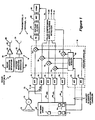
Figure 1 shows a radar system including a blanker, a sidelobe canceler and a spoofer; -
Figure 2 shows an illustrative receive antenna pattern (the sum pattern) of the system ofFigure 1 and the blanker beam pattern; -
Figure 3 shows a radar system including a blanker, a sidelobe canceler and a spoofer utilizing nulling in the jammer direction; -
Figure 4 shows the nulled sum beam pattern from the system ofFigure 3 ; -
Figure 5 shows the nulled blanker beam pattern from the system ofFigure 3 ; -
Figure 6 shows a blanker/spoofer configuration for use with the system ofFigure 3 ; -
Figure 7 illustrates the pattern of one of the crossed linear arrays ofFigure 6 ; and -
Figure 8 illustrates the pattern of the other one of the crossed linear arrays ofFigure 6 . - Before departing on a detailed description of the invention, it may helpful to review the concept for spoofing, blanking, and sidelobe cancellation which overcomes several limitations of traditional blanking and cancellation methods.
- A spoofer typically radiates signals in the direction of jammers so that smart sidelobe jammers cannot deduce the radar frequency and spot jam, thereby increasing the jammer ERP by the ratio of barrage jamming bandwidth to the spot jamming bandwidth. For sophisticated jammers employing DRFM's (digital RF memory) the spot jamming could be as narrow as the radar search bandwidth, and the ratio of jamming bandwidth to signal bandwidth as high as 30 dB. The waveform of a spoofer should contain multiple signals, each with the envelope and phase modulation of the radar signal, and dispersed across the total operating band in the frequency slots or bands assigned to the radar, with the spoofer signal seen by the jammer higher than the radar signal in the sidelobes.
- A blanker channel typically provides the same signal processing matched filter as for the main beam channel. Its input is from an antenna which has more gain than the sidelobes of the main beam in the angle of the region likely to cause interference signals. A comparison between channels at the output of the processor rejects detections in the main beam channel if the signal in the sidelobe channel is stronger. Signals blanked in this process include strong sidelobe clutter, larger aircraft, repeater jammers, or jammers which radiate radar like chirp signals. A major problem with sidelobe blankers is the inability to achieve adequate gain relative to the main beam sidelobes, so as to minimize noise in the blanker channel from degrading main beam performance. These problems are exacerbated when the sidelobe blanker phase center is displaced from that of the main beam, because multipath reflections can reduce incoming signals in the blanker while increasing them in the main beam.
- Sidelobe cancellation typically requires at least one auxiliary channel per jammer. The auxiliary channel antenna should, like the blanker, have more gain than the main beam sidelobe in the direction of the jammer. Typically, near omni-directional antennas are used for the auxiliary antennas however the amplification required to provide a strong enough signal has two deleterious effects. First, the noise from the sidelobe canceller (SLC) adds to the main beam, degrading sensitivity and, secondly, sidelobes in other directions increase.
- The solution to these problems shall now be described in the context of a solid-state module phased array radar. We will discuss an example, to illustrate the concept, of an antenna with an N = 10,000 element array at X-band. Elements are assumed to have a cosine gain dependence on scan angle, so the broadside element gain is


where ε2 = fraction of power redirected into the sidelobes;
σ0 = rms radar phase error: and
σa = rms fractional amplitude error. - Thus, using an electronic countermeasures (ECM) map, nulls can be placed in the direction of jammers with an error limited floor of-15 dBi, equivalent to a sidelobe level of 10 log (4N) + 15 = 61 dB below the main beam. It would result in excessively high loss to obtain these sidelobe levels with traditional weighting. Open loop nulling achieves the benefit of low sidelobes in the jammer direction without the heavy weighting loss.
- Sidelobe cancelers make up the additional jamming rejection. A single element having 6 dB gain will produce +6 dBi - (-15dBi) = 21dB more signal strength than the main beam. The attenuation (provided digitally in the signal processor) applied to the auxiliary channel will permit cancellation with less than 1 dB noise carryover loss. Also, with open loop nulling, the cancellation required is typically 20 dB less than for conventional systems, making the canceler system less susceptible to phase and amplitude unbalance between main and auxiliary channels.
- The phased array radars to date have traditionally combined quadrant symmetric elements or subarrays to form sum E, azimuth ΔAz, and elevation (ΔE1) beams. As shown below, there is also a ΔΔ output which is shown to be the product of the ΔAz and the ΔEl channels. This fourth channel provides an additional degree of freedom so that the array can null a main beam jammer and still provide normalized azimuth and elevation channels. The relationships

- An architecture for spoofing, blanking and jammer cancellation is described above. Extending the architecture to include a single main beam jammer means that the number of omni-directional auxiliary elements required for canceling n jammer can be augmented by the Δ-Δ channel with the ΔΔ channel being used to cancel one jammer, whether it is in the sidelobes or in the main beam.
- It has been pointed out that the jammer nulling must be carried out as a single process; e.g., it is not possible to carry out sidelobe cancellation and mainlobe cancellation as sequential operations, since all jammers appear in all the reference elements. This is probably because, typically, the concern has been about sidelobe jammers or main beam jammers, but not both threats simultaneously.
- If we have a four quadrant antenna beam, with the upper left quadrant being quadrant A, the upper right quadrant being quadrant B, the lower left quadrant being quadrant C and the lower right quadrant being quadrant D and letting v represent the elevation axis and u represent the azimuth axis, then:


- With main beam jamming, form:


- It should be appreciated that some of the limitations of conventional sidelobe cancelers/blankers include wide field of view coverage for auxiliaries, which leads to low gain auxiliary antenna designs resulting in high carry-over noise in sidelobe cancelers, loss of sensitivity in sidelobe blanker (SLB) and vulnerability to multipath lobing in a sidelobe canceler/sidelobe blanker (SLC/SLB). In blanker operation, the blanker channel has a separate receiver/signal processor matched filter and the target declaration requires the output channel signal exceed the blanker channel output. Another major problem is providing enough gain in the auxiliary antenna to avoid SNR loss and multipath loss. A blanker can be a separate (fourth) channel in addition to the Σ channel, the α channel and the β channel. If the system uses sidelobe canceling, all four channels ideally should have a canceler and some blankers only work in the absence of jamming. In a spoofer operation, a spoofer radiates noise-like or radar waveform replica-like signals dispersed across the band. In the absence of spoofer, a smart jammer can listen to radar signal and jam a fraction of the radar band, increasing J/N by up to 20-30 dB. Typically, short range radars have long dwells and long range radars have targets beyond jammer range. The objective is to have a spoofer signal seen by a smart jammer larger than a signal from radar transmit sidelobes by a ratio of total bandwidth to search signal bandwidth of up to 30dB. In sidelobe canceler operation, the sidelobe cancellation requires at least one auxiliary element per jammer. Like a SLB, SLC auxiliary antenna should cover the field of view of expected jammers, yet have high gain. Using near omni-directional antennas, limitations include noise from SLC which adds to the main beam signal and also sidelobes in other directions increase.
- To over come the latter, a system concept of operation for a solid state phased array radar includes an ECM map that locates jammers. Open loop receive weights (using phase/amplitude module settings) place nulls in jammer directions (limited by errors to-15dBi). Single element omni element antennas provide 6 dB gain for an auxiliary antenna. Gain of SLC to signal channel is +15 - (-6) = 21dB which minimizes carryover noise. It has been observed that cancellation requirements are typically 20dB less than for conventional system and are less sensitive to multipath.
- An antenna for use with the contemplated system includes a vertical linear array to provide a Beam A, the vertical linear array being phased to provide high gain near horizon for high power jammers, but which can be tapered to include moderate gain for higher elevation, lower powered jammers. The antenna further includes a horizontal linear array that provides a Beam B, the horizontal linear beam being omni in elevation, but points beams in direction of the jammers. A differencing (Beam A minus Beam B) output beam is also provided which has uniform gain in azimuth (for SLB function) and has -15dBi nulls in the jammer directions (for SLC function). The beam A also serves as a spoofer beam on transmit. Important features of the latter includes minimizing SLC sensitivity loss, reducing multipath effects on blanker and SLC, avoids increasing sidelobes with SLC in other than the jammer direction, preserves simultaneous operation of SLB and SLC functions and provides a low power spoofer capability for defeating smart (DRFM) jammers.
- Referring now to
Figure 1 , aradar system 10 includes a receiver 14 having ablanker channel 13 and asidelobe canceler 16 and further includes atransmitter 12 including aspoofer 18. Thetransmitter 12 includes amain channel 20 having aradar waveform generator 22 which generates radar signals in predetermined frequency slots or bands over an operating band, such as the X band, for coupling to aradar signal transmitter 24. Thetransmitter 24 amplifies the radar signals and couples the amplified signals 25 to a radar transmitantenna 26 for transmission of the radar signals in order to detect targets of interest. - The
spoofer 18 includes aspoofer waveform generator 30 for generating spoofer signals capable of diverting or otherwise confusing smart sidelobe jammers from the actual radar signals transmitted byantenna 26. Stated differently, the spoofer signals are selected in order to effectively prevent smart sidelobe jammers from ascertaining the frequency of the radar signals 25. As one example, the spoofer signal has the same envelope as theradar signal 25 but different phase modulation over the entire operating band in the frequency slots or bands assigned to the radar signals 25, with an amplitude greater than the amplitude of the radar signal, at least in the sidelobes. The spoofer signal is coupled to aspoofer transmitter 32 for further coupling to, and transmission by aspoofer antenna 34. The spoofer signals are radiated in the direction of jammers. It will be appreciated by those of ordinary skill in the art that various transmitter and antenna configurations are possible for use with thetransmitter 12 ofFigure 1 . - The receiver 14 includes a receive
antenna array 40 having a plurality Nmain beam subarrays 1 and associated electronics (including, for example, splitters, phase shifters, summing and difference circuits) for forming a sum beam pattern or signalΣ 42, an azimuth difference pattern or signal ΔAz 44, an elevation difference pattern or signalΔEl 46 and an optional difference/difference pattern or signal ΔΔ 48. Also provided in theantenna array 40 are a further plurality of nauxiliary antennas 1 provided for use with thesidelobe canceler 16. In the illustrative embodiment, theantenna array 40 is a planar array of solid state modules, having phase and amplitude control. - The
blanker channel 13 includes adiscrete blanker antenna 70 which, in the illustrative embodiment is provided in the form of a linear array. The signals from the array elements are summed bysummer 72 to provide the blanker beam pattern BL orsignal 43. - Each of the beam patterns or signals is coupled to a respective moving target indicator (MTI)
circuit 76 for processing. Each MTI circuit includes a filter, such as a delay line filter, designed to reduce the effects of clutter. To this end, the time domain radar signal provided by the input beam patterns or signals is converted into a frequency domain signal and summed with a predetermined weight (which is a function of either known or modeled clutter frequencies and which are calculated from the estimation of covariance between the sidelobe canceler and other channels) in order to produce notches in the respective bandpass filter associated with each MTI circuit to modify the beam pattern in the passband. The resulting signals are then converted back into the time domain at the output of therespective MTI circuit 76. - Considering the
sidelobe canceler 16, each of the n sidelobe canceler auxiliary antenna 1' is likewise coupled to anMTI circuit 76 of the type described above for processing. Anadaptive weight circuit 80 is responsive to the signals received by the auxiliary antenna and modified by therespective MTI circuit 76 in order to determine a plurality of weights necessary to be introduced to each channel in order to null the sidelobes of the respective pattern. In the illustrative embodiment, thesidelobe canceler 16 provides sidelobe cancellation in the direction of jammers. Thus, at least one auxiliary antenna per jammer is necessary. The auxiliary antennas 1' are omnidirectional antennas. - Further signal processing in each channel is provided by a
pulse compression circuit 82, a Doppler matchedfilter 84, and athreshold detection circuit 90, as is conventional. Note that the blanker and sum beam channels have identical matched filters. - Referring also to
Figure 2 , thesum beam pattern 42 is shown in relation to theblanker beam pattern 43. The sum beam pattern includes acenter beam 42a and a plurality ofsidelobes 42b. As noted, the gain of theblanker beam 43 is greater than the gain of themain beam sidelobes 42b. - Since the input to the blanker channel is from an
antenna 70 having higher gain than the main beam sidelobes in the angle region likely to cause interference signals, comparison of the output of the blanker and main beam channels by acomparison circuit 90 can be used to determine if a main beam detection is valid. More particularly, if detections in the main beam are stronger than detections in the blanker beam, then the main beam detections are determined to be valid (since excessive interference was not detected by the blanker). Alternatively, if detections in the blanker beam are stronger than detections in the main beam, then main beam detections are rejected as invalid due to excessive interference. - As noted above however, because of the high gain requirement of the
blanker antenna 70, system noise levels are amplified which results in degradation of main beam sensitivity. As a result, a blanker of the type shown inFigure 1 is typically disabled in the presence of strong sidelobe jamming. - Referring to
Figure 3 , in which like elements toFigure 1 are referred to with like reference numbers, a solid state phasedarray radar system 100 according to the invention is shown to include a transmitter 104 and a receiver 106. Theradar system 100 differs from theradar system 10 ofFigure 1 in at least the following significant respects. First, a combinedantenna array 120 is used for the blanker and spoofer functions as well as for the main beam and sidelobe canceler functions and, secondly, theradar system 100 includes open loop nulling in the direction of jammers in the main beam and blanker channels. In the illustrative embodiment, the combinedantenna array 120 includes a pair of crossed linear arrays, as will be described below in conjunction withFigure 6 . Further in the illustrative embodiment, the open loop nulling is implemented by an openloop nulling circuit 52 including anECM mapping circuit 112 and aweight processor 114. - The
antenna array 120 includes a main beam aperture as well as a crossed linear array which is used for the blanker and spoofer functions described below in conjunction withFigure 6 . Thus, thespoofer transmitter 32, in response to aspoofer waveform generator 30, provides spoofer signals 33 to theantenna array 120 for transmission. Furthermore, theantenna array 120 includes electronics (including, for example, splitters, phase shifters, summing and difference circuits) for generating a sumbeam pattern Σ 60, a blankerbeam pattern BL 62, an azimuthdifference pattern ΔAz 64, an elevation difference pattern ΔEl 66 and an optional difference/difference pattern ΔΔ 68. - More particularly, considering the open
loop nulling circuit 52, theECM mapping circuit 112 is operable to map the direction of jammers. This is achieved by scanning the array beam(s) along the region containing jammers and measuring and storing jammer locations. With the jammer direction information provided by themapping circuit 112, theweight processor 114 calculates a plurality ofweights 140 necessary for theantenna 120 to introduce a null in the direction of the jammers by adjusting phase/amplitude antenna module settings. Weights for each beam are calculated using optimum filter weighting theory to produce the desired null. Each of the resulting beam patterns thus has nulls in the directions of the jammers and may be referred to as nulled sumbeam pattern Σ 60, nulled blankerbeam pattern BL 62, nulled azimuthdifference pattern ΔAz 64, nulled elevation difference pattern ΔE1 66 and nulled difference/difference pattern ΔΔ 68. - The
auxiliary elements 124 are provided by n omnidirectional antenna elements, each of which is coupled to thesidelobe canceler 16. More particularly, each auxiliary element is coupled to arespective MTI circuit 76 of the sidelobe canceler 16, as shown. - Referring also to
Figure 4 , the nulledsum beam pattern 60 is shown having nulls in the two illustratedjammer directions sum beam 60 is insensitive to the jamming energy in these directions. - Referring to
Figure 5 , the nulledblanker beam pattern 62 is shown to have nulls at thesame jammer directions - It should now be appreciated that an advantage of the above-described open loop nulling technique is that certain drawbacks of the sidelobe canceler 16 are overcome. More particularly, the
sidelobe canceler 16 makes up the additional jamming rejection. As a result of the above-described open loop nulling, the sidelobeauxiliary antenna 124, will have 21dB more gain in the jamming direction than the blanker beam, rather than 14dB less gain as would be the case in absence of open loop nulling in the jammer direction. More particularly, a single auxiliary element having 6 dB gain will produce +6 dBi - (-15dBi) = 21dB more signal than the main beam. The attenuation (provided digitally in the signal processor) applied to the auxiliary channel will permit cancellation with less than 1 dB noise carryover loss. Also, with open loop nulling, the cancellation required is typically 20 dB less than for conventional systems, making the canceler system less susceptible to phase and amplitude unbalance between main and auxiliary channels. - The optional ΔΔ channel can be used to augment the open loop nulling described above. In particular, the ΔΔ output is the product of the ΔAz and ΔE1 channels. The ΔΔ channel can be used as an additional auxiliary channel, to cancel one jammer. More particularly, the ΔΔ channel can be used to null either a sidelobe or a mainlobe jammer, and still permit normalized azimuth and elevation channels. This is because a normalized monopulse estimate is obtained from two beams (either ΔΔ and ΔAz or ΔΔ and ΔE1), both of which can be pointed at the jammer to null the jammer while producing an off-null target response. The modified angle channels (ΔE1', ΔAz', and ΔΔ') adapt the weights multiplying the sum channel to produce the closed loop null.
- Referring also to
Figure 6 , a preferred configuration for providing the blanker and spoofer portion of theantenna array 120 is shown to include a pair oflinear arrays - The crossed
linear arrays antenna array aperture 174, as shown, or alternatively may be positioned outside of the main aperture. Advantages of providing the linear arrays integral to main aperture are less total aperture area and reduced multipath effects due to having identical phase centers for the main and blanker beams. -
Beam 170 is omnidirectional in the u direction (azimuth) and directional in the v direction (elevation). In the illustrative embodiment, the beam covers on the order of 10 degrees in elevation, where most interference signals will be seen. - In the illustrative embodiment, the
array 120 includes 10,000 elements, each assumed to have cosine gain dependence on scan angle. For the square antenna shown, eachlinear array 


- The
beam 180 is omnidirectional in elevation (v) and directional in azimuth (u). In particular,beam 180 is used to point the beams of the horizontallinear array 180 in the azimuth direction of the jammers. When beams 170 and 180 are differenced and weighted by theantenna array 120, the resulting beam is omnidirectional in azimuth and has -15dBi nulls in the direction of the jammers, as is illustrated by the nulled sum beam ofFigure 4 . - Referring to
Figure 7 , the pattern for thelinear array 170 is shown with the x axis being the direction cosine for elevation. Referring toFigure 8 , the pattern for thelinear array 180 is shown with the x axis being the direction cosine for azimuth. - Advantageously, the
linear arrays - As shown in
Figure 1 , aradar system 10 includes five SLC loops and blanker, elevation, azimuth, and main beams. For a system using pulse compression and MTI waveforms, the first processing step (post A/D converter) is the removal of clutter, using a 3-5 pulse canceler. Weights are calculated from the estimation of covariance between SLC and other channels. Pulse compression/Doppler filtering is followed by detection thresholding, with main beam detections reported only if they are stronger than the blanker channel. - It should be noted that the blanker channel is treated here as another beam, like the sum and difference channels. Thus, there is a need to provide sidelobe cancellation of jammers in the blanker channel, if blanking of sidelobe pulsed interference is preserved in the presence of sidelobe barrage jamming.
- The difficulty stems from the need to have high blanker gain, while simultaneously requiring the SLC auxiliary antennas to have higher gain than the blanker.
- The approach is shown in
Figure 6 which shows a pair of linear antennas A and B at right angles to each other. These may be outside the main antenna, but are shown integral to the main aperture in this example. Advantages include less total aperture area and reduced multipath effects by having identical phase centers for blanker and main beams. - Beams A and B double as spoofers on transmit and blankers on receive. Beam A is omni-directional in the u direction (azimuth) while directional in v to cover the horizon and elevations up to about 10 degrees, where most interference will be seen. For the square antenna shown, each linear array has

gain 20 dBe (26 dBi). The beamwidth is
- Beam B is omni-directional in the v (elevation) direction and is used to point beams in the azimuth direction of jammers. When A and B are differenced, the modified beam will be omni-directional in azimuth but will have -15 dBi nulls in the direction of jammers. Thus, the SLC auxiliaries will have 21 dB more gain in the jamming direction than the blanker beam, instead of 10 dB less. This allows the blanker to operate in sidelobe barrage jamming.
- The concept described provides a method for providing near thermal noise limited performance for the radar in a sidelobe jamming environment, on both main and blanker beams. Most existing systems disable the blanker in barrage jamming. This concept is applicable to systems which require sidelobe blanking and jammer cancellation.
Claims (10)
- A radar system comprising:a plurality of antennas (174) including a main antenna having a main beam pattern and a blanker antenna (170,180) having a blanker beam pattern;a beam forming network (52,120) including a nulling circuit (52), said beam forming network (52, 120) being coupled to said main antenna for forming a sum beam pattern having a null in the direction of a jammer and to the blanker antenna (170,180) for forming a blanker beam pattern having a null in the direction of the jammer;means (76, 82, 84, 86) for processing radar signals received in the sum and blanker beam patterns; anda comparison circuit (90) for comparing the level of signals received in said sum beam pattern with the level of signals received in said blanker beam pattern in order to determine when radar signals received in said main beam pattern are representative of a valid target, characterised in that the nulling circuit (52) is an open loop circuit for nulling in the direction of the jammer, the nulling circuit (52) being responsive to the detected jammer direction to provide the null in the sum beam pattern and in the blanker beam pattern; and in that a spoofer (18) is coupled to the blanker antenna (170,180), the blanker antenna comprising linear arrays (170,180).
- A radar system according to claim 1, characterised by a plurality of auxiliary antennas (124) coupled to a sidelobe canceller (16).
- A radar system according to claim 2, characterised in that said sidelobe canceller (16) comprises:an adaptive weight circuit (80) responsive to radar signals received by said auxiliary antennas (124) for determining a plurality of sidelobe cancellation weights;a sum beam adder (75) for adding one of said sidelobe cancellation weights to said radar signals (60) received in said sum beam pattern; anda blanker adder (75) for adding one of said sidelobe cancellation weights to said radar signals (62) received in said blanker beam pattern.
- A radar system according to claims 2 or 3, characterised in that each of said plurality of auxiliary antennas (124) is an omnidirectional antenna.
- A radar system according to any preceding claim, characterised by a radar transmitter (20) for transmitting a radar signal.
- A radar system according to any preceding claim, characterised in that the blanker antenna comprises a pair of linear arrays (170, 180) disposed orthogonal with respect to one another.
- A radar system according to any preceding claim, characterised in that the nulling circuit (52) has an ECM map circuit (112)for detecting the direction of a jammer.
- A radar system according to claim 2, characterised in that the sidelobe canceller comprises an auxiliary antenna means (124), an adaptive weight circuit (80), and a summer circuit (75).
- A method of operating a radar system comprising the steps of:transmitting a radar signal;receiving radar signals using a main beam pattern and a blanker beam pattern;forming a sum beam pattern from the main beam pattern;processing radar signals received in said sum beam pattern;processing radar signals received in said blanker beam pattern;comparing (90) the level of signals received in said sum beam pattern with the level of signals received in said blanker beam pattern in order to determine when radar signals received in said main beam pattern are representative of a valid target;detecting the direction of a jammer; andperforming nulling to provide a null in the detected direction of the jammer in the sum beam pattern and to provide a null in the detected direction of the jammer in the blanker beam pattern, characterised in that the nulling is open loop nulling, and by the step of transmitting a spoofer signal (33) capable of preventing a smart sidelobe jammer from detecting the frequency of the transmitted radar signal, the step of receiving radar signals using a blanker beam pattern including receiving radar signals at a blanker antenna comprising linear arrays (170,180), and the step of transmitting a spoofer signal including radiating the spoofer signal from the blanker antenna.
- A method according to claim 9, characterised by determining (80) a plurality of sidelobe cancellation weights;
adding one of said sidelobe cancellation weights to said radar signals received by said sum beam pattern; and
adding one of said sidelobe cancellation weights to said radar signals received by said blanker beam pattern.
Applications Claiming Priority (3)
| Application Number | Priority Date | Filing Date | Title |
|---|---|---|---|
| US12028099P | 1999-02-16 | 1999-02-16 | |
| US120280P | 1999-02-16 | ||
| PCT/US2000/003762 WO2000052497A2 (en) | 1999-02-16 | 2000-02-14 | Radar system having spoofer, blanker and canceler |
Publications (2)
| Publication Number | Publication Date |
|---|---|
| EP1159635A2 EP1159635A2 (en) | 2001-12-05 |
| EP1159635B1 true EP1159635B1 (en) | 2010-04-07 |
Family
ID=22389311
Family Applications (1)
| Application Number | Title | Priority Date | Filing Date |
|---|---|---|---|
| EP00939273A Expired - Lifetime EP1159635B1 (en) | 1999-02-16 | 2000-02-14 | Radar system having spoofer, blanker and canceler |
Country Status (7)
| Country | Link |
|---|---|
| US (1) | US6538597B1 (en) |
| EP (1) | EP1159635B1 (en) |
| JP (1) | JP4545320B2 (en) |
| AU (1) | AU5438500A (en) |
| DE (1) | DE60044122D1 (en) |
| IL (2) | IL144487A0 (en) |
| WO (1) | WO2000052497A2 (en) |
Cited By (1)
| Publication number | Priority date | Publication date | Assignee | Title |
|---|---|---|---|---|
| US20210389419A1 (en) * | 2018-10-25 | 2021-12-16 | Saab Ab | Radar system for jammed environments |
Families Citing this family (24)
| Publication number | Priority date | Publication date | Assignee | Title |
|---|---|---|---|---|
| WO2002014896A1 (en) * | 2000-08-11 | 2002-02-21 | Alenia Marconi Systems Limited | Method of interference suppression in a radar system |
| US7068209B2 (en) * | 2002-11-18 | 2006-06-27 | Lockheed Martin Corporation | System and method for detecting and jamming emitter signals |
| US6803582B2 (en) * | 2002-11-29 | 2004-10-12 | Oregon Health & Science University | One dimensional beam blanker array |
| US7046190B2 (en) * | 2003-07-25 | 2006-05-16 | Raytheon Company | Process for phase-derived range measurements |
| US7038615B2 (en) * | 2003-10-10 | 2006-05-02 | Raytheon Company | Efficient technique for estimating elevation angle when using a broad beam for search in a radar |
| US6977610B2 (en) * | 2003-10-10 | 2005-12-20 | Raytheon Company | Multiple radar combining for increased range, radar sensitivity and angle accuracy |
| JP3799421B2 (en) * | 2004-02-26 | 2006-07-19 | 防衛庁技術研究本部長 | Radar equipment |
| EP1731921A1 (en) * | 2005-06-01 | 2006-12-13 | Nederlandse Organisatie voor toegepast-natuurwetenschappelijk onderzoek TNO | Radar system for aircraft |
| EP2165212A2 (en) * | 2007-06-01 | 2010-03-24 | Raytheon Company | Methods and apparatus for using interferometry to prevent spoofing of ads-b targets |
| US7728764B2 (en) * | 2007-10-19 | 2010-06-01 | Raytheon Company | Sidelobe blanking characterizer system and method |
| US8144051B2 (en) | 2008-09-05 | 2012-03-27 | Raytheon Company | Adaptive sidelobe blanking for motion compensation |
| US8193974B2 (en) | 2009-03-04 | 2012-06-05 | Honeywell International Inc. | Systems and methods for suppressing ambiguous peaks from stepped frequency techniques |
| US9075128B2 (en) | 2012-01-09 | 2015-07-07 | Raytheon Company | Grating lobe mitigation in presence of simultaneous receive beams |
| US9674836B2 (en) * | 2014-01-27 | 2017-06-06 | Spectrum Effect, Inc. | Method and system for coexistence of radar and communication systems |
| US9772402B2 (en) * | 2014-06-09 | 2017-09-26 | Src, Inc. | Multiplatform GMTI radar with adaptive clutter suppression |
| US9285469B1 (en) | 2014-10-29 | 2016-03-15 | Src, Inc. | Multiplatform GMTI radar with enhanced SNR, monopulse |
| US11047967B2 (en) * | 2018-07-12 | 2021-06-29 | Southwest Research Institute | Removal of directwave high frequency signal for ionospheric sounder return processing |
| CN109143198B (en) * | 2018-09-29 | 2023-03-21 | 北京无线电测量研究所 | Side lobe suppression method and system |
| US11811507B1 (en) * | 2019-06-10 | 2023-11-07 | Bae Systems Information And Electronic Systems Integration Inc. | Adaptive digital radio frequency memory for coherent response synthesis |
| CN111638492B (en) * | 2020-04-24 | 2023-03-31 | 安徽博微长安电子有限公司 | Method for improving sidelobe cancellation performance |
| CN111693933B (en) * | 2020-06-18 | 2023-08-25 | 成都锦江电子系统工程有限公司 | Radar signal instantaneous wide-azimuth direction finding system |
| CN112346003B (en) * | 2020-10-20 | 2023-12-29 | 西安空间无线电技术研究所 | Single-beam direction finding system based on equipotential optimization |
| CN113884990B (en) * | 2021-08-17 | 2023-06-13 | 西安电子科技大学 | Two-stage self-adaptive multi-main-lobe interference suppression method and system based on combined beam pattern reconstruction |
| CN113917410B (en) * | 2021-12-13 | 2022-02-22 | 湖南芯普电子科技有限公司 | Double-station radar collaborative anti-deception jamming method and device and computer equipment |
Family Cites Families (16)
| Publication number | Priority date | Publication date | Assignee | Title |
|---|---|---|---|---|
| US5307069A (en) * | 1973-11-02 | 1994-04-26 | Hughes Aircraft Company | Improved radar receiver system |
| US3943511A (en) * | 1974-05-31 | 1976-03-09 | Hughes Aircraft Company | Spike enable circuit |
| US5442365A (en) | 1975-09-02 | 1995-08-15 | Lewis; Bernard L. | Technique for processing interference-contaminated radar energy |
| US5365234A (en) | 1977-03-23 | 1994-11-15 | United States Of America As Represented By The Secretary Of The Navy | High-resolution sidelobe-canceller auxiliary antennas |
| US5502448A (en) * | 1977-08-30 | 1996-03-26 | The United States Of America As Represented By The Secretary Of The Navy | Method and means for short pulse interference rejection |
| US4298872A (en) * | 1980-05-27 | 1981-11-03 | Hughes Aircraft Company | Sidelobe blanking system |
| DE3028225C1 (en) * | 1980-07-25 | 1992-09-17 | Siemens Ag | Radar receiver |
| US5245347A (en) * | 1980-12-29 | 1993-09-14 | Raytheon Company | All weather tactical strike system (AWTSS) and method of operation |
| NL8402559A (en) * | 1984-08-21 | 1986-03-17 | Hollandse Signaalapparaten Bv | SIDE LOOP 'BLANKING' CIRCUIT. |
| US4959653A (en) * | 1989-08-23 | 1990-09-25 | Massachusetts Institute Of Technology | Adaptive sidelobe blanker |
| JPH041584A (en) * | 1990-04-18 | 1992-01-07 | Mitsubishi Electric Corp | Method and device for suppressing disturbance wave on radar equipment |
| JPH04143688A (en) * | 1990-10-05 | 1992-05-18 | Mitsubishi Electric Corp | Radar signal processor |
| JPH04172284A (en) * | 1990-11-05 | 1992-06-19 | Mitsubishi Electric Corp | Side lobe blanking apparatus |
| US5600326A (en) | 1991-12-16 | 1997-02-04 | Martin Marietta Corp. | Adaptive digital beamforming architecture and algorithm for nulling mainlobe and multiple sidelobe radar jammers while preserving monopulse ratio angle estimation accuracy |
| NL9302002A (en) * | 1993-11-19 | 1995-06-16 | Hollandse Signaalapparaten Bv | Radar device equipped with ECCM facilities. |
| NL9400973A (en) * | 1994-06-15 | 1996-01-02 | Hollandse Signaalapparaten Bv | Radar device. |
-
2000
- 2000-02-14 EP EP00939273A patent/EP1159635B1/en not_active Expired - Lifetime
- 2000-02-14 US US09/503,267 patent/US6538597B1/en not_active Expired - Lifetime
- 2000-02-14 WO PCT/US2000/003762 patent/WO2000052497A2/en active Application Filing
- 2000-02-14 IL IL14448700A patent/IL144487A0/en not_active IP Right Cessation
- 2000-02-14 DE DE60044122T patent/DE60044122D1/en not_active Expired - Lifetime
- 2000-02-14 JP JP2000602657A patent/JP4545320B2/en not_active Expired - Fee Related
- 2000-02-14 AU AU54385/00A patent/AU5438500A/en not_active Abandoned
-
2001
- 2001-07-22 IL IL144487A patent/IL144487A/en unknown
Cited By (1)
| Publication number | Priority date | Publication date | Assignee | Title |
|---|---|---|---|---|
| US20210389419A1 (en) * | 2018-10-25 | 2021-12-16 | Saab Ab | Radar system for jammed environments |
Also Published As
| Publication number | Publication date |
|---|---|
| IL144487A0 (en) | 2002-05-23 |
| JP2002538467A (en) | 2002-11-12 |
| DE60044122D1 (en) | 2010-05-20 |
| JP4545320B2 (en) | 2010-09-15 |
| WO2000052497A2 (en) | 2000-09-08 |
| AU5438500A (en) | 2000-09-21 |
| WO2000052497A9 (en) | 2001-10-25 |
| EP1159635A2 (en) | 2001-12-05 |
| US6538597B1 (en) | 2003-03-25 |
| IL144487A (en) | 2006-09-05 |
| WO2000052497A3 (en) | 2001-09-07 |
Similar Documents
| Publication | Publication Date | Title |
|---|---|---|
| EP1159635B1 (en) | Radar system having spoofer, blanker and canceler | |
| US5371506A (en) | Simultaneous multibeam approach for cancelling multiple mainlobe jammers while preserving monopulse angle estimation accuracy on mainlobe targets | |
| US6697009B2 (en) | Adaptive digital beamforming architecture for target detection and angle estimation in multiple mainlobe and sidelobe jamming | |
| EP1267444B1 (en) | Adaptive digital sub-array beamforming and deterministic sum and difference beamforming with jamming cancellation and monopulse ratio preservation | |
| Brown et al. | STAP for clutter suppression with sum and difference beams | |
| Farina et al. | Electronic counter-countermeasures | |
| Brookner | MIMO radar demystified and where it makes sense to use | |
| EP1167995B1 (en) | Matrix monopulse ratio radar processor for two target azimuth and elevation angle determination | |
| US5311192A (en) | Polarization ECCM technique for radar systems | |
| Rabideau et al. | Ubiquitous MIMO multifunction digital array radar... and the role of time-energy management in radar | |
| Skolnik | Improvements for air-surveillance radar | |
| Kuschel | VHF/UHF radar. Part 2: Operational aspects and applications | |
| US20030184473A1 (en) | Adaptive digital sub-array beamforming and deterministic sum and difference beamforming, with jamming cancellation and monopulse ratio preservation | |
| US6653969B1 (en) | Dispersive jammer cancellation | |
| Brookner | MIMO radars demystified—and their conventional equivalents | |
| US6369746B1 (en) | Simultaneous nulling in low sidelobe sum and difference antenna beam patterns | |
| Sedehi et al. | Reduced order jammer cancellation scheme based on double adaptivity | |
| Brookner | Cognitive adaptive array processing (Caap)-Adaptivity made easy | |
| Brookner | Cognitive adaptive array processing (CAAP)—Its time has come | |
| US4851847A (en) | Method for eliminating self-screening noise jamming in radar systems | |
| Nohara et al. | Space-based radar signal processing baselines for air, land and sea applications | |
| US4924230A (en) | Search detection apparatus | |
| Butt et al. | A Robust Approach for Mitigation of Noise Jamming in Linear Array Systems | |
| Brookner | MIMO versus conventional radar performance against jammers | |
| Baseri et al. | Testing adaptive jamming cancellation algorithms using a digital beamforming array |
Legal Events
| Date | Code | Title | Description |
|---|---|---|---|
| PUAI | Public reference made under article 153(3) epc to a published international application that has entered the european phase |
Free format text: ORIGINAL CODE: 0009012 |
|
| 17P | Request for examination filed |
Effective date: 20010828 |
|
| AK | Designated contracting states |
Kind code of ref document: A2 Designated state(s): AT BE CH CY DE DK ES FI FR GB GR IE IT LI LU MC NL PT SE |
|
| AX | Request for extension of the european patent |
Free format text: AL;LT;LV;MK;RO;SI |
|
| R17D | Deferred search report published (corrected) |
Effective date: 20011025 |
|
| RAP1 | Party data changed (applicant data changed or rights of an application transferred) |
Owner name: RAYTHEON COMPANY |
|
| RBV | Designated contracting states (corrected) |
Designated state(s): DE FR GB |
|
| 17Q | First examination report despatched |
Effective date: 20041220 |
|
| 17Q | First examination report despatched |
Effective date: 20041220 |
|
| GRAP | Despatch of communication of intention to grant a patent |
Free format text: ORIGINAL CODE: EPIDOSNIGR1 |
|
| GRAS | Grant fee paid |
Free format text: ORIGINAL CODE: EPIDOSNIGR3 |
|
| GRAA | (expected) grant |
Free format text: ORIGINAL CODE: 0009210 |
|
| AK | Designated contracting states |
Kind code of ref document: B1 Designated state(s): DE FR GB |
|
| REG | Reference to a national code |
Ref country code: GB Ref legal event code: FG4D |
|
| REF | Corresponds to: |
Ref document number: 60044122 Country of ref document: DE Date of ref document: 20100520 Kind code of ref document: P |
|
| PLBE | No opposition filed within time limit |
Free format text: ORIGINAL CODE: 0009261 |
|
| STAA | Information on the status of an ep patent application or granted ep patent |
Free format text: STATUS: NO OPPOSITION FILED WITHIN TIME LIMIT |
|
| 26N | No opposition filed |
Effective date: 20110110 |
|
| REG | Reference to a national code |
Ref country code: FR Ref legal event code: PLFP Year of fee payment: 16 |
|
| PGFP | Annual fee paid to national office [announced via postgrant information from national office to epo] |
Ref country code: DE Payment date: 20150210 Year of fee payment: 16 |
|
| PGFP | Annual fee paid to national office [announced via postgrant information from national office to epo] |
Ref country code: FR Payment date: 20150210 Year of fee payment: 16 Ref country code: GB Payment date: 20150211 Year of fee payment: 16 |
|
| REG | Reference to a national code |
Ref country code: DE Ref legal event code: R119 Ref document number: 60044122 Country of ref document: DE |
|
| GBPC | Gb: european patent ceased through non-payment of renewal fee |
Effective date: 20160214 |
|
| REG | Reference to a national code |
Ref country code: FR Ref legal event code: ST Effective date: 20161028 |
|
| PG25 | Lapsed in a contracting state [announced via postgrant information from national office to epo] |
Ref country code: FR Free format text: LAPSE BECAUSE OF NON-PAYMENT OF DUE FEES Effective date: 20160229 Ref country code: DE Free format text: LAPSE BECAUSE OF NON-PAYMENT OF DUE FEES Effective date: 20160901 Ref country code: GB Free format text: LAPSE BECAUSE OF NON-PAYMENT OF DUE FEES Effective date: 20160214 |