EP0654592A1 - Zweitakt-Dieselbrennkraftmaschine - Google Patents
Zweitakt-Dieselbrennkraftmaschine Download PDFInfo
- Publication number
- EP0654592A1 EP0654592A1 EP94114969A EP94114969A EP0654592A1 EP 0654592 A1 EP0654592 A1 EP 0654592A1 EP 94114969 A EP94114969 A EP 94114969A EP 94114969 A EP94114969 A EP 94114969A EP 0654592 A1 EP0654592 A1 EP 0654592A1
- Authority
- EP
- European Patent Office
- Prior art keywords
- engine
- control valve
- scavenging
- exhaust
- aperture
- Prior art date
- Legal status (The legal status is an assumption and is not a legal conclusion. Google has not performed a legal analysis and makes no representation as to the accuracy of the status listed.)
- Granted
Links
Images


Classifications
-
- F—MECHANICAL ENGINEERING; LIGHTING; HEATING; WEAPONS; BLASTING
- F02—COMBUSTION ENGINES; HOT-GAS OR COMBUSTION-PRODUCT ENGINE PLANTS
- F02D—CONTROLLING COMBUSTION ENGINES
- F02D13/00—Controlling the engine output power by varying inlet or exhaust valve operating characteristics, e.g. timing
- F02D13/02—Controlling the engine output power by varying inlet or exhaust valve operating characteristics, e.g. timing during engine operation
- F02D13/028—Controlling the engine output power by varying inlet or exhaust valve operating characteristics, e.g. timing during engine operation for two-stroke engines
- F02D13/0284—Variable control of exhaust valves only
-
- F—MECHANICAL ENGINEERING; LIGHTING; HEATING; WEAPONS; BLASTING
- F02—COMBUSTION ENGINES; HOT-GAS OR COMBUSTION-PRODUCT ENGINE PLANTS
- F02B—INTERNAL-COMBUSTION PISTON ENGINES; COMBUSTION ENGINES IN GENERAL
- F02B33/00—Engines characterised by provision of pumps for charging or scavenging
- F02B33/02—Engines with reciprocating-piston pumps; Engines with crankcase pumps
- F02B33/04—Engines with reciprocating-piston pumps; Engines with crankcase pumps with simple crankcase pumps, i.e. with the rear face of a non-stepped working piston acting as sole pumping member in co-operation with the crankcase
-
- F—MECHANICAL ENGINEERING; LIGHTING; HEATING; WEAPONS; BLASTING
- F02—COMBUSTION ENGINES; HOT-GAS OR COMBUSTION-PRODUCT ENGINE PLANTS
- F02D—CONTROLLING COMBUSTION ENGINES
- F02D13/00—Controlling the engine output power by varying inlet or exhaust valve operating characteristics, e.g. timing
- F02D13/02—Controlling the engine output power by varying inlet or exhaust valve operating characteristics, e.g. timing during engine operation
- F02D13/04—Controlling the engine output power by varying inlet or exhaust valve operating characteristics, e.g. timing during engine operation using engine as brake
-
- F—MECHANICAL ENGINEERING; LIGHTING; HEATING; WEAPONS; BLASTING
- F02—COMBUSTION ENGINES; HOT-GAS OR COMBUSTION-PRODUCT ENGINE PLANTS
- F02D—CONTROLLING COMBUSTION ENGINES
- F02D41/00—Electrical control of supply of combustible mixture or its constituents
- F02D41/30—Controlling fuel injection
- F02D41/38—Controlling fuel injection of the high pressure type
-
- F—MECHANICAL ENGINEERING; LIGHTING; HEATING; WEAPONS; BLASTING
- F02—COMBUSTION ENGINES; HOT-GAS OR COMBUSTION-PRODUCT ENGINE PLANTS
- F02M—SUPPLYING COMBUSTION ENGINES IN GENERAL WITH COMBUSTIBLE MIXTURES OR CONSTITUENTS THEREOF
- F02M26/00—Engine-pertinent apparatus for adding exhaust gases to combustion-air, main fuel or fuel-air mixture, e.g. by exhaust gas recirculation [EGR] systems
- F02M26/01—Internal exhaust gas recirculation, i.e. wherein the residual exhaust gases are trapped in the cylinder or pushed back from the intake or the exhaust manifold into the combustion chamber without the use of additional passages
-
- F—MECHANICAL ENGINEERING; LIGHTING; HEATING; WEAPONS; BLASTING
- F02—COMBUSTION ENGINES; HOT-GAS OR COMBUSTION-PRODUCT ENGINE PLANTS
- F02B—INTERNAL-COMBUSTION PISTON ENGINES; COMBUSTION ENGINES IN GENERAL
- F02B75/00—Other engines
- F02B75/02—Engines characterised by their cycles, e.g. six-stroke
- F02B2075/022—Engines characterised by their cycles, e.g. six-stroke having less than six strokes per cycle
- F02B2075/025—Engines characterised by their cycles, e.g. six-stroke having less than six strokes per cycle two
-
- F—MECHANICAL ENGINEERING; LIGHTING; HEATING; WEAPONS; BLASTING
- F02—COMBUSTION ENGINES; HOT-GAS OR COMBUSTION-PRODUCT ENGINE PLANTS
- F02B—INTERNAL-COMBUSTION PISTON ENGINES; COMBUSTION ENGINES IN GENERAL
- F02B2275/00—Other engines, components or details, not provided for in other groups of this subclass
- F02B2275/16—Indirect injection
-
- F—MECHANICAL ENGINEERING; LIGHTING; HEATING; WEAPONS; BLASTING
- F02—COMBUSTION ENGINES; HOT-GAS OR COMBUSTION-PRODUCT ENGINE PLANTS
- F02B—INTERNAL-COMBUSTION PISTON ENGINES; COMBUSTION ENGINES IN GENERAL
- F02B3/00—Engines characterised by air compression and subsequent fuel addition
- F02B3/06—Engines characterised by air compression and subsequent fuel addition with compression ignition
-
- F—MECHANICAL ENGINEERING; LIGHTING; HEATING; WEAPONS; BLASTING
- F02—COMBUSTION ENGINES; HOT-GAS OR COMBUSTION-PRODUCT ENGINE PLANTS
- F02D—CONTROLLING COMBUSTION ENGINES
- F02D9/00—Controlling engines by throttling air or fuel-and-air induction conduits or exhaust conduits
- F02D9/02—Controlling engines by throttling air or fuel-and-air induction conduits or exhaust conduits concerning induction conduits
- F02D2009/0201—Arrangements; Control features; Details thereof
- F02D2009/0291—Throttle control device for throttle being disposed in a two-stroke engine transfer passage
-
- F—MECHANICAL ENGINEERING; LIGHTING; HEATING; WEAPONS; BLASTING
- F02—COMBUSTION ENGINES; HOT-GAS OR COMBUSTION-PRODUCT ENGINE PLANTS
- F02D—CONTROLLING COMBUSTION ENGINES
- F02D2250/00—Engine control related to specific problems or objectives
- F02D2250/18—Control of the engine output torque
-
- F—MECHANICAL ENGINEERING; LIGHTING; HEATING; WEAPONS; BLASTING
- F02—COMBUSTION ENGINES; HOT-GAS OR COMBUSTION-PRODUCT ENGINE PLANTS
- F02D—CONTROLLING COMBUSTION ENGINES
- F02D2400/00—Control systems adapted for specific engine types; Special features of engine control systems not otherwise provided for; Power supply, connectors or cabling for engine control systems
- F02D2400/04—Two-stroke combustion engines with electronic control
-
- Y—GENERAL TAGGING OF NEW TECHNOLOGICAL DEVELOPMENTS; GENERAL TAGGING OF CROSS-SECTIONAL TECHNOLOGIES SPANNING OVER SEVERAL SECTIONS OF THE IPC; TECHNICAL SUBJECTS COVERED BY FORMER USPC CROSS-REFERENCE ART COLLECTIONS [XRACs] AND DIGESTS
- Y02—TECHNOLOGIES OR APPLICATIONS FOR MITIGATION OR ADAPTATION AGAINST CLIMATE CHANGE
- Y02T—CLIMATE CHANGE MITIGATION TECHNOLOGIES RELATED TO TRANSPORTATION
- Y02T10/00—Road transport of goods or passengers
- Y02T10/10—Internal combustion engine [ICE] based vehicles
- Y02T10/12—Improving ICE efficiencies
Definitions
- This invention concerns a two-cycle diesel engine comprising an exhaust passage with an exhaust control valve for controlling the aperture of said exhaust passage and a scavenge passage arrangement with a scavenging control valve for controlling the rate of scavenging.
- Some vehicles equipped with two-cycle diesel engines are equipped with an exhaust control valve to variably control the position of the upper edge of the exhaust passage, which makes possible the variable control of the exhaust timing and compression ratio.
- the above mentioned exhaust control valve and scavenging control valve are generally driven by step motors, entailing limitations upon the speed with at they may be operated.
- the response of the aforementioned control valves is sluggish, with respect to the response speed for controlling fuel injection, and as a result, black smoke or white smoke can be generated.
- the rate of fuel injection is premised on the condition that the various control valves have been controlled to the appropriate aperture, however, due to the delay in their operation, they may have not yet reached the appropriate aperture position, and the increased rate of fuel injection at this time is believed to lead to the above described problems such as black smoke generation.
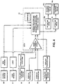
- this objective is performed in that a detection means is provided for detecting an engine operating condition and a control device is provided for controlling the aperture of the exhaust control valve and the scavenging control valve respectively, in response to said engine operating condition.
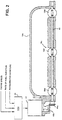
- 1 is a water cooled, three cylinder, two-cycle diesel engine.
- the bottom surface 2a of the cylinder block 3 of said engine 1 is attached to the crankcase 3.
- Three sets of crank chambers 4 are present in the bottom of area of the cylinder block 2 and crankcase 3.
- the cylinder head 5 is mounted to the top surface 2a of the above mentioned cylinder block 2.
- Cylindrical plug retention holes 21c are present in the side surface 5a of the foregoing cylinder head 5, and these open into the main combustion chambers 8. Hot plugs 21 are inserted into said plug retention holes 21c and are held in place by bolts 23.
- Linking holes 21b join said auxiliary combustion chambers with the foregoing main combustion chambers 8. Injectors 25a and glow plugs 25b have also been inserted into the foregoing auxiliary combustion chambers 22.
- Three sets of air intake openings 15a are present in the bottom part of the above mentioned cylinder block 2 and these air intake openings 15a pass through to the foregoing respective crank chambers 4.
- An air intake manifold 16a is connected to each of said air intake openings.
- each of these crank chambers 4 is linked to the above mentioned air intake manifold 16a by oil return holes 51 in the bottom of each crank chamber and through the boss 52. Oil that has accumulated in the crank chambers 4 may thus be returned to the inside of the air intake manifold 16a.
- Reed valves 17 have also been placed in the foregoing various air intake openings 15a.
- the structure of these reed valves 17 is such that the opening 17b, which is present in the valve bodies 17a is opened and closed by valve reed 17c.
- the reed valves 17 operate so that when the foregoing piston 7 rises, the negative pressure created in the crank chamber causes the valves to automatically open to let air into the crank chamber 4; when the piston descends, the positive pressure closes the reed valves to prevent the air from escaping.
- the opposite side of the above mentioned air intake openings 15a in the foregoing cylinder block 2 comprise scavenging adjustment openings 15b which link the aforementioned various crank chambers.
- Said scavenging adjustment openings 15b link the three crank chambers 4 with a common scavenging chamber 16b, and the various linking openings in said scavenging chamber 16b are fitted with scavenging control valves 16c which can be opened and closed.
- the foregoing scavenging control valves 16c consist of a valve shaft 40 to which three valve plates 16d have been affixed, and said valve shaft 40 is rotatably driven by a step motor 42 by bevel gears 41a and 41b.
- This structure allows the above mentioned scavenging adjustment openings 15b to be simultaneously opened or closed by the foregoing valve plates 16d.
- ECU 44 controls the above mentioned step motor 42 to open and close the valve depending upon the operating state of engine 1 (engine rpm, rate of fuel injection, accelerator aperture, etc.).
- the scavenging chamber 16b is connected to the various crank chambers 4, thereby effectively expanding the volume of the crank chambers. This decreases the scavenging pressure and reduces the rate of air intake, causing the internal EGR gas to increase and the combustion temperature to decrease.
- the crank chambers 4 assume their normal volumes and adequate scavenging takes place.
- a set of exhaust ports 18 is present in the top of the above mentioned cylinder block 2 for each of the cylinders.
- These exhaust ports 18 consist of a primary exhaust port 18b, which connects the primary exhaust opening 18a to the outside of the cylinder, and of a pair of auxiliary exhaust openings on the top side of the foregoing primary exhaust opening, which connect to the outside through the auxiliary exhaust port 18d which merges into the middle of the above mentioned primary exhaust port 18b.
- a catalyst is also attached downstream of the aforementioned exhaust port 18 to cleanse the exhaust gases.
- the above mentioned auxiliary exhaust port 18d can be opened and closed by an exhaust control device 19.
- This exhaust control device 19 can vary the exhaust timing and compression ratio, and it is positioned coaxially with the auxiliary exhaust ports 18d in the foregoing cylinder block 3.
- the exhaust control device 19 consists of a drive mechanism 19b which can open and close three exhaust valves 19a that open and close the foregoing auxiliary exhaust ports 18d.
- the foregoing exhaust valve units 19a consist of round rods upon which an arc-shaped valve area has been formed, and comprise linking areas by which they are linked to each other.
- the above mentioned drive mechanism 19b connects the outside end of the foregoing exhaust valves 19a with a drive shaft, and said drive shaft is connected by a gear array to a drive motor, which operates to open and close the valves according to the operational state of the engine under control by the foregoing ECU 44.
- the exhaust timing is the point where the top surface of piston 7 is positioned at the upper edge of the auxiliary exhaust opening 18c, which is more advanced than when the exhaust control valve 19a is closed.
- the compression ratio is determined by the volume of the primary combustion chamber 8 when the top surface of the piston 7 is at the upper edge of the auxiliary exhaust opening 18c, and is less than it is when the exhaust control valve 19a is closed.
- Adjacent to and on both sides of the foregoing main exhaust opening in the above mentioned cylinder block 2 is a pair of main scavenging openings 18e. Opposite the aforementioned main exhaust opening 18a is opposing scavenging opening 18f, and these various scavenging openings 18e, 18f communicate with the crank chambers 4 of said cylinders.
- a pair of oil holes 2e and 2f are present in the cylinder block 2 for each of the cylinders to supply lubricating oil to the sliding surfaces of the pistons.
- Said oil holes 2e, 2f pass through the cylinder block 2 in a direction perpendicular to the crankshaft. When viewed in the direction of the cylinder axis A ( Figure 3), they are displaced on either side of said cylinder axis A, and when viewed along the crankshaft direction ( Figure 1), the above mentioned oil holes 2e, 2f can be seen to be linked to a lubricating oil pump 46 operationally controlled by ECU 44.
- a projecting box-shaped boss 3b which opens downward and is positioned around the bottom wall perimeter of the above mentioned crankcase 3.
- a box shaped balancer cover 26 is attached to the opening on the top side of said boss 3b to create a balancer chamber 27.
- the balancer shaft 28 is housed within this balancer chamber 27 and it runs parallel to the crankshaft 12.
- the balancer shaft 28 is supported by bearings (not shown) that are held between the adjoining surfaces of the foregoing boss 3b and the balancer cover 26.
- the above mentioned balancer chamber also serves as a breather chamber which separates the oil and air mixture supplied from a pump (not shown). The separated air then passes through air outlet 27c to the air intake passage while the oil collects in oil reservoir 32a from where it is fed to an oil pump which circulates it to various places.
- this embodiment is equipped with an engine rpm sensor 50, load sensor 51, and accelerator aperture sensor 52, a main switch sensor 53, and a starter switch sensor 54, a coolant temperature sensor 55, etc., which enable the detection of the engine operating condition.
- ECU 44 determines the current engine operational mode from the information it receives on engine rpm, engine load, accelerator aperture and the contact conditions for the main and starter switches. Based upon the determination of the operational mode, the engine rpm, engine load, coolant temperature and the like, it controls the apertures of the above mentioned exhaust control valve 19a and scavenging control valve 16c based upon a graphics of operating parameters and the like to control the opening and closing of each of the control valves 19a and 16c.
- Step S1 When the ignition key is turned to the "accessory" position, the main switch is on (Step S1), and at this time, since the engine rpm is 0, it is determined that the engine is in the prestart mode, and the below-listed prestarting mode control is performed (Step S2). To wit, to prevent it from sticking when the engine is stopped, the above mentioned exhaust control valve undergoes an opening and closing operation prior to starting that serves to clean said exhaust control valve 19a. After that, the aforementioned exhaust control valve 19a is rotated to its fully closed position. When this prestart mode control is completed, a pilot light is lighted to indicate that the prestart preparations have been completed (Step S3).
- Step 4 when the ignition key is rotated to the "start” position, the starter switch turns on (Step 4). A determination is then made that the engine is in the starting mode due to the fact that the engine rpm is at the cranking rpm level (about 450 rpm), which is lower than Nst, and the exhaust control valve is maintained in the fully closed position as a part of the start mode control (Step S5). When the engine rpm increase above the Nst level, then the aforementioned starter switch is turned off (Steps S6, S7). However, if the foregoing engine rpm is lower than Nst as shown by (A) in Figure 7 (in the start mode range), there is a return to the above mentioned start mode control (Step S5).
- Step S8 After the foregoing starter switch has been turned off, and when the engine rpm level is under the NidON level as shown by (B) in Figure 7 (when the idle switch is on and operations are in the idle mode range), if the accelerator aperture is 0 (Steps S8, S9) then a determination is made that the engine is in the idle mode, and the idle mode control is performed by stably maintaining the exhaust control valve 19a in the fully closed position (Step S10). The control program keeps returning to this idle mode control so long as the engine rpm remains under NidOFF (Step S11).
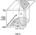
- Steps S12, S13 When the accelerator pedal is pressed, the engine rpm rises above the NidOFF level as shown by (C) in Figure 7, and a determination is made that the engine is in the travel mode, with control performed accordingly based on a three-dimensional control graphics (Steps S12, S13). As shown in Figure 6, this three-dimensional graphics control is based upon the engine rpm and engine load: the valve aperture for the above mentioned exhaust control valve 19a is determined by three-dimensional graphics as shown in Figures 8 and 9 (Steps S13-1 through S13-4) by means of the above mentioned drive mechanism 19b driving the foregoing exhaust control valve 19a (Step S13-5). Comparisons are then made between the detected valve aperture and the target valve aperture, and feedback control is performed (Steps S13-6, S13-7).
- Step S14 when the ignition switched is rotated to the "off" position, the main switch is turned off (Step S14), and when the engine stops, the travel mode is terminated.
- said exhaust control valve 19a is then opened and closed to complete a cleaning operation (Step S15).
- Figures (1) represents the engine's low speed range (in the vicinity of, or slightly above the NidON rpm range).
- the exhaust control valve remains fully closed regardless of the rate of fuel injection q.
- the rate of fuel injection q corresponds to the shaft torque (load).
- the pressure wave of the exhaust gas can be effectively utilized to improve filling efficiency, increasing the output by the amount needed to inhibit the generation of smoke. Since the compression ratio can be increased, the combustion properties can be improved, thereby making it possible to lower HC emissions and improve fuel economy.
- (2) and (5) indicate the middle and high rpm ranges; the more the rpm is increased over the mid-speed rpm, the more the exhaust control valve 19a's fully closed range gradually approaches the low fuel injection rate level. In other words, the greater the rate of fuel injection (high load), even if the engine rpm is low, the more the exhaust control valve is opened, the higher the engine rpm and the greater the expansion of the fully open range of the exhaust control valve 19a.
- (4) represents a middle aperture range.
- (3) represents the condition when the foregoing rate of fuel injection q is 0, that is, when the accelerator opening speed is 0, in the so-called engine braking operational state.
- the exhaust control valve 19a is fully closed, no matter what the engine rpm.
- the cross section of the exhaust passage is reduced thereby, reducing in turn the rate of air intake into the combustion chambers, and the lowering of the catalytic temperature also will be inhibited.
- the control operations during engine braking will be described below.
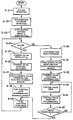
- Step S1 When the main switch is turned on (Step S1) and a determination is made that the engine is in the prestart mode, the initial position of the scavenging valve 16c is detected, and control is exercised to fully close said scavenging control valve (Step S2).
- Step S2 rotation of the scavenging control valve is performed by the above mentioned step motor 42.
- the magnitude is by the number of steps, it would take to rotate it from the fully open to the fully closed position, plus a few extra steps to be sure and then said valve is deemed fully closed at the point where further rotation becomes impossible. That step number is then substituted for the then existing step number corresponding to the fully closed position.
- Steps S2-S5 When the above mentioned prestart mode control has been completed, a pilot light is lighted, and when the ignition key is turned to the "start" position, the starter switch is turned ON and a determination is made that the engine is in the starting mode, whereupon starting mode control is excercised to maintain the scavenging control valve 16c in the fully closed position (Steps S2-S5).
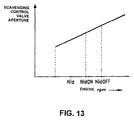
- Step S10 the aperture of the scavenging control valve is adjusted in proportion to the engine rpm (see the two-dimensional graphics in Figure 13) under idle mode control (Step S10).
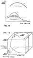
- Steps S11-S13 This three-dimensional graphics control is of the same type that was exercised for the exhaust control valve 19a, however, the three-dimensional graphicss are the ones characterized in Figures 11 and 12.
- Figure 11 shows the engine rpm on the horizontal axis and the shaft torque on the vertical axis; curves A and B are the normal and maximum torque curves, respectively.
- Figure 12 shows the valve apertures of the scavenging control valve using engine rpm and rate of fuel injection as parameters. The rate of smoke generation is approximately 0% in the region under the torque generation curve A, and it increases as the torque approaches curve B, where it reaches 20%. In the operating range from curve A to B, the scavenging control valve 16c is fully closed, and in the region under curve A, that is, the region where no smoke is generated, aperture control is exercised over the scavenging control valve 16c.
- the apertures of the exhaust control valve 19a and the scavenging control valve 16c were controlled according to the operational mode of the engine, and the effects discussed further below, were observed.
- the exhaust control valve 19a is rotated to the fully closed position in the prestart mode, and maintained in that position in the starting mode to improve the starting properties of the engine.
- the foregoing exhaust control valve 19a when in the idle mode, the foregoing exhaust control valve 19a is maintained in the fully closed position so that the exhaust gas pressure wave can be effectively utilized to improve the filling efficiency, inhibit the generation of smoke, and improve output by that same magnitude. Also, the closure of the exhaust control valve 19a increases the compression ratio to improve combustion properties, decrease HC emissions, and improve fuel economy.
- the scavenging control valve 16c By opening the scavenging control valve 16c as described above, the volume of the various crank chambers is effectively increased to reduce the scavenging pressure and the rate of scavenging, that is, the rate of air intake into the combustion chambers is decreased. Accordingly, the rate of low temperature air being exhausted through the exhaust system decreases, inhibiting the cooling of the catalyst. Also, the closing of the exhaust control valve 19a increases the compression ratio, and the heat of compression further inhibits the cooling of the foregoing catalyst. In addition, the foregoing heat of compression sustains temperatures in the combustion chamber, so that when fuel injection is resumed, misfiring, white smoke and HC generation are effectively inhibited.
- the control device computes the accelerator opening speed Va from the detected values for engine rpm and accelerator aperture, and then compares this value with the maximum operating speed Vb for the above mentioned exhaust control valve 19a and scavenging control valve 16c. If the accelerator opening speed Va is higher than the maximum operating speed Vb, then the foregoing exhaust control valve 19a is opened, and the scavenging control valve 16c is closed at their respective maximum operating speeds, and in addition, the apertures of those control valves 19a, 16c are detected (Steps S25, 26).
- the three-dimensional graphics described for the first embodiment above is searched in order to determine the rate of fuel injection corresponding to the control valve apertures, and the fuel injection pump is controlled accordingly (Steps S27-29). The decision on the rate of fuel to be injected is based upon the requirement for the exhaust control valve 19a and the scavenging control valve 16c, whichever is lower.
- Step S24 determines whether the accelerator opening speed Va is less than the valve operation speed Vb. If it is determined in the above mentioned Step S24 that the accelerator opening speed Va is less than the valve operation speed Vb, then the engine load is detected (Step S30) and the three-dimensional graphics is searched for the proper valve apertures (Steps S31, 32), the valve drive motors are operated to achieve said apertures (Step S33), and then the valve position is detected to make any required corrections for the target aperture (Steps S34, 35).
- the control valve aperture position takes priority and the rate of fuel injection is determined in accordance with said aperture. Accordingly when an operational delay of the control valves occurs during rapid acceleration, the rate of fuel injection is gradually increased in parallel with said control valve aperture to prevent problems such as the generation of black smoke.
- the foregoing embodiments comprised a scavenging chamber 16b which was linked to the respective crank chamber to control the rate of scavenging, but it would also be possible to set up independent scavenging chambers for each crank chamber, with their own scavenging control valves to open and close off said chambers.
- the engine operation control device for two-cycle engines in Claim 1 of this invention determines the operational mode of the engine based on its operating condition and controls the control valves based upon said operational mode during the prestart stage, during starting and in each operational mode to realize the appropriate apertures for the above mentioned exhaust and scavenging control valves. Engine starting properties and engine emissions during starting are improved thereby.
- the engine operation control device closes the above mentioned exhaust control valve and/or opens the above mentioned scavenging control valve during engine braking to reduce the volume of air intake and to prevent cooling of the catalyst, thereby improving the cleansing performance of said catalyst.
- the engine operation control device makes corrections to the rate of fuel injection at those times when the accelerator opening speed is greater than the maximum operational speed of the exhaust control valve and the scavenging control valve, based on the apertures of the foregoing exhaust control valve and scavenging control valve, which are being set based on engine rpm and accelerator aperture, to prevent problems such as the generation of black smoke caused by the operational delay of the exhaust control valve and the scavenging control valve with respect to the rapid increase in the rate of fuel injection.
Landscapes
- Engineering & Computer Science (AREA)
- Chemical & Material Sciences (AREA)
- Combustion & Propulsion (AREA)
- Mechanical Engineering (AREA)
- General Engineering & Computer Science (AREA)
- Electrical Control Of Air Or Fuel Supplied To Internal-Combustion Engine (AREA)
- Control Of Throttle Valves Provided In The Intake System Or In The Exhaust System (AREA)
- Output Control And Ontrol Of Special Type Engine (AREA)
Applications Claiming Priority (2)
| Application Number | Priority Date | Filing Date | Title |
|---|---|---|---|
| JP236499/93 | 1993-09-22 | ||
| JP23649993A JP3375686B2 (ja) | 1993-09-22 | 1993-09-22 | 2サイクルディーゼルエンジンの運転制御装置 |
Publications (2)
| Publication Number | Publication Date |
|---|---|
| EP0654592A1 true EP0654592A1 (de) | 1995-05-24 |
| EP0654592B1 EP0654592B1 (de) | 1998-03-25 |
Family
ID=17001641
Family Applications (1)
| Application Number | Title | Priority Date | Filing Date |
|---|---|---|---|
| EP94114969A Expired - Lifetime EP0654592B1 (de) | 1993-09-22 | 1994-09-22 | Zweitakt-Dieselbrennkraftmaschine |
Country Status (3)
| Country | Link |
|---|---|
| EP (1) | EP0654592B1 (de) |
| JP (1) | JP3375686B2 (de) |
| DE (1) | DE69409203T2 (de) |
Cited By (2)
| Publication number | Priority date | Publication date | Assignee | Title |
|---|---|---|---|---|
| US5832881A (en) * | 1995-06-29 | 1998-11-10 | Orbital Engine Company (Australia) Pty Limited | Supplementary port for two stroke engine |
| CN106168171A (zh) * | 2015-05-19 | 2016-11-30 | 温特图尔汽柴油公司 | 操作大型柴油发动机的方法、其用途以及大型柴油发动机 |
Families Citing this family (2)
| Publication number | Priority date | Publication date | Assignee | Title |
|---|---|---|---|---|
| DE60003627T2 (de) * | 2000-01-05 | 2004-06-09 | Robert Bosch Gmbh | Verfahren zur Regelung der Wärmeverluste eines katalytischen Konverters während Schubbetrieb |
| JP6672348B2 (ja) * | 2018-02-02 | 2020-03-25 | 株式会社Ihi原動機 | パイロット燃料ガス供給装置 |
Citations (8)
| Publication number | Priority date | Publication date | Assignee | Title |
|---|---|---|---|---|
| US4793347A (en) * | 1986-01-29 | 1988-12-27 | Honda Giken Kogyo Kabushiki Kaisha | Exhaust timing control device for two cycle engines |
| GB2226596A (en) * | 1988-12-21 | 1990-07-04 | Fuji Heavy Ind Ltd | Regulating two-stroke engine intake and exhaust |
| GB2233388A (en) * | 1989-06-29 | 1991-01-09 | Fuji Heavy Ind Ltd | Injection timing control in a spark-ignition direct fuel injection engine |
| GB2234293A (en) * | 1989-07-29 | 1991-01-30 | Fuji Heavy Ind Ltd | Timing control of a two-stroke engine exhaust rotary valve |
| EP0469596A2 (de) * | 1990-07-31 | 1992-02-05 | Yamaha Hatsudoki Kabushiki Kaisha | Mehrzylinder Zweitakt-Brennkraftmaschine |
| US5178104A (en) * | 1989-09-29 | 1993-01-12 | Yamaha Hatsudoki Kabushiki Kaisha | Two cycle diesel engine |
| JPH0586922A (ja) * | 1991-09-27 | 1993-04-06 | Yamaha Motor Co Ltd | 筒内噴射式2サイクルエンジンの燃焼制御装置 |
| EP0603914A1 (de) * | 1992-12-25 | 1994-06-29 | Yamaha Hatsudoki Kabushiki Kaisha | Brennkraftmaschine und Verfahren zu seinem Betrieb |
-
1993
- 1993-09-22 JP JP23649993A patent/JP3375686B2/ja not_active Expired - Fee Related
-
1994
- 1994-09-22 DE DE69409203T patent/DE69409203T2/de not_active Expired - Fee Related
- 1994-09-22 EP EP94114969A patent/EP0654592B1/de not_active Expired - Lifetime
Patent Citations (8)
| Publication number | Priority date | Publication date | Assignee | Title |
|---|---|---|---|---|
| US4793347A (en) * | 1986-01-29 | 1988-12-27 | Honda Giken Kogyo Kabushiki Kaisha | Exhaust timing control device for two cycle engines |
| GB2226596A (en) * | 1988-12-21 | 1990-07-04 | Fuji Heavy Ind Ltd | Regulating two-stroke engine intake and exhaust |
| GB2233388A (en) * | 1989-06-29 | 1991-01-09 | Fuji Heavy Ind Ltd | Injection timing control in a spark-ignition direct fuel injection engine |
| GB2234293A (en) * | 1989-07-29 | 1991-01-30 | Fuji Heavy Ind Ltd | Timing control of a two-stroke engine exhaust rotary valve |
| US5178104A (en) * | 1989-09-29 | 1993-01-12 | Yamaha Hatsudoki Kabushiki Kaisha | Two cycle diesel engine |
| EP0469596A2 (de) * | 1990-07-31 | 1992-02-05 | Yamaha Hatsudoki Kabushiki Kaisha | Mehrzylinder Zweitakt-Brennkraftmaschine |
| JPH0586922A (ja) * | 1991-09-27 | 1993-04-06 | Yamaha Motor Co Ltd | 筒内噴射式2サイクルエンジンの燃焼制御装置 |
| EP0603914A1 (de) * | 1992-12-25 | 1994-06-29 | Yamaha Hatsudoki Kabushiki Kaisha | Brennkraftmaschine und Verfahren zu seinem Betrieb |
Non-Patent Citations (1)
| Title |
|---|
| PATENT ABSTRACTS OF JAPAN vol. 17, no. 423 (M - 1458) 6 August 1993 (1993-08-06) * |
Cited By (2)
| Publication number | Priority date | Publication date | Assignee | Title |
|---|---|---|---|---|
| US5832881A (en) * | 1995-06-29 | 1998-11-10 | Orbital Engine Company (Australia) Pty Limited | Supplementary port for two stroke engine |
| CN106168171A (zh) * | 2015-05-19 | 2016-11-30 | 温特图尔汽柴油公司 | 操作大型柴油发动机的方法、其用途以及大型柴油发动机 |
Also Published As
| Publication number | Publication date |
|---|---|
| EP0654592B1 (de) | 1998-03-25 |
| DE69409203D1 (de) | 1998-04-30 |
| JP3375686B2 (ja) | 2003-02-10 |
| JPH0791260A (ja) | 1995-04-04 |
| DE69409203T2 (de) | 1998-07-16 |
Similar Documents
| Publication | Publication Date | Title |
|---|---|---|
| US5988137A (en) | Controller of in-cylinder injection spark ignition internal combustion engine | |
| US5494008A (en) | Valve timing control apparatus for engine | |
| EP1891314B1 (de) | Vorrichtung und verfahren zum anlassen einer brennkraftmaschine | |
| EP0529638B1 (de) | Brennkraftmaschine mit Funkenentzündung | |
| EP0806559B1 (de) | Verfahren zur Steuerung des Betriebs einer direkteinspritzenden Zweitaktbrennkraftmaschine | |
| EP0831219B1 (de) | Verfahren zur Betriebssteuerung einer Brennkraftmaschine | |
| JPH08312401A (ja) | 筒内噴射型火花点火式内燃機関の燃料噴射制御装置 | |
| US6135095A (en) | Engine control | |
| US6116228A (en) | Control for engine | |
| US5113826A (en) | Intake air control system for internal combustion engine | |
| US5575246A (en) | Operational control device for two-cycle engines | |
| EP0831217B1 (de) | Mehrzylinderbrennkraftmaschine | |
| US6148777A (en) | Control for direct injected two cycle engine | |
| EP0831227B1 (de) | Steuergerät einer direkt einspritzenden funkengezündeten Brennkraftmaschine | |
| US6367446B1 (en) | Internal combustion engine control apparatus and method | |
| US6067956A (en) | Knock control for engine | |
| KR0121446B1 (ko) | 불꽃점화식 2싸이클엔진의 냉각장치 | |
| JPH06185380A (ja) | 多気筒内燃機関の燃料制御方法 | |
| EP0654592B1 (de) | Zweitakt-Dieselbrennkraftmaschine | |
| JPH0814092A (ja) | 2サイクルエンジンの燃焼制御装置 | |
| JPH102244A (ja) | エンジンの運転制御装置 | |
| JP4180995B2 (ja) | 圧縮着火内燃機関の制御装置 | |
| KR0130022B1 (ko) | 차량용불꽃점화식 2싸이클엔진의 감속제어장치 | |
| JPH05332155A (ja) | 縦置型多気筒内燃機関 | |
| JP4046824B2 (ja) | 筒内噴射式2サイクルエンジン |
Legal Events
| Date | Code | Title | Description |
|---|---|---|---|
| PUAI | Public reference made under article 153(3) epc to a published international application that has entered the european phase |
Free format text: ORIGINAL CODE: 0009012 |
|
| AK | Designated contracting states |
Kind code of ref document: A1 Designated state(s): DE FR GB |
|
| 17P | Request for examination filed |
Effective date: 19951123 |
|
| 17Q | First examination report despatched |
Effective date: 19960130 |
|
| GRAG | Despatch of communication of intention to grant |
Free format text: ORIGINAL CODE: EPIDOS AGRA |
|
| GRAG | Despatch of communication of intention to grant |
Free format text: ORIGINAL CODE: EPIDOS AGRA |
|
| GRAH | Despatch of communication of intention to grant a patent |
Free format text: ORIGINAL CODE: EPIDOS IGRA |
|
| GRAH | Despatch of communication of intention to grant a patent |
Free format text: ORIGINAL CODE: EPIDOS IGRA |
|
| GRAA | (expected) grant |
Free format text: ORIGINAL CODE: 0009210 |
|
| AK | Designated contracting states |
Kind code of ref document: B1 Designated state(s): DE FR GB |
|
| PG25 | Lapsed in a contracting state [announced via postgrant information from national office to epo] |
Ref country code: FR Free format text: LAPSE BECAUSE OF FAILURE TO SUBMIT A TRANSLATION OF THE DESCRIPTION OR TO PAY THE FEE WITHIN THE PRESCRIBED TIME-LIMIT Effective date: 19980325 |
|
| REF | Corresponds to: |
Ref document number: 69409203 Country of ref document: DE Date of ref document: 19980430 |
|
| EN | Fr: translation not filed | ||
| PG25 | Lapsed in a contracting state [announced via postgrant information from national office to epo] |
Ref country code: GB Free format text: LAPSE BECAUSE OF NON-PAYMENT OF DUE FEES Effective date: 19980922 |
|
| PLBE | No opposition filed within time limit |
Free format text: ORIGINAL CODE: 0009261 |
|
| STAA | Information on the status of an ep patent application or granted ep patent |
Free format text: STATUS: NO OPPOSITION FILED WITHIN TIME LIMIT |
|
| 26N | No opposition filed | ||
| GBPC | Gb: european patent ceased through non-payment of renewal fee |
Effective date: 19980922 |
|
| PGFP | Annual fee paid to national office [announced via postgrant information from national office to epo] |
Ref country code: DE Payment date: 20020925 Year of fee payment: 9 |
|
| PG25 | Lapsed in a contracting state [announced via postgrant information from national office to epo] |
Ref country code: DE Free format text: LAPSE BECAUSE OF NON-PAYMENT OF DUE FEES Effective date: 20040401 |