EP0654248B1 - Load transfer member for osteosynthesis - Google Patents
Load transfer member for osteosynthesis Download PDFInfo
- Publication number
- EP0654248B1 EP0654248B1 EP94118281A EP94118281A EP0654248B1 EP 0654248 B1 EP0654248 B1 EP 0654248B1 EP 94118281 A EP94118281 A EP 94118281A EP 94118281 A EP94118281 A EP 94118281A EP 0654248 B1 EP0654248 B1 EP 0654248B1
- Authority
- EP
- European Patent Office
- Prior art keywords
- load transfer
- bone
- transfer member
- member according
- thread
- Prior art date
- Legal status (The legal status is an assumption and is not a legal conclusion. Google has not performed a legal analysis and makes no representation as to the accuracy of the status listed.)
- Expired - Lifetime
Links
Images


Classifications
-
- A—HUMAN NECESSITIES
- A61—MEDICAL OR VETERINARY SCIENCE; HYGIENE
- A61B—DIAGNOSIS; SURGERY; IDENTIFICATION
- A61B17/00—Surgical instruments, devices or methods, e.g. tourniquets
- A61B17/56—Surgical instruments or methods for treatment of bones or joints; Devices specially adapted therefor
- A61B17/58—Surgical instruments or methods for treatment of bones or joints; Devices specially adapted therefor for osteosynthesis, e.g. bone plates, screws, setting implements or the like
- A61B17/68—Internal fixation devices, including fasteners and spinal fixators, even if a part thereof projects from the skin
- A61B17/70—Spinal positioners or stabilisers ; Bone stabilisers comprising fluid filler in an implant
- A61B17/7001—Screws or hooks combined with longitudinal elements which do not contact vertebrae
- A61B17/7002—Longitudinal elements, e.g. rods
-
- A—HUMAN NECESSITIES
- A61—MEDICAL OR VETERINARY SCIENCE; HYGIENE
- A61B—DIAGNOSIS; SURGERY; IDENTIFICATION
- A61B17/00—Surgical instruments, devices or methods, e.g. tourniquets
- A61B17/56—Surgical instruments or methods for treatment of bones or joints; Devices specially adapted therefor
- A61B17/58—Surgical instruments or methods for treatment of bones or joints; Devices specially adapted therefor for osteosynthesis, e.g. bone plates, screws, setting implements or the like
- A61B17/68—Internal fixation devices, including fasteners and spinal fixators, even if a part thereof projects from the skin
- A61B17/70—Spinal positioners or stabilisers ; Bone stabilisers comprising fluid filler in an implant
- A61B17/7001—Screws or hooks combined with longitudinal elements which do not contact vertebrae
- A61B17/7041—Screws or hooks combined with longitudinal elements which do not contact vertebrae with single longitudinal rod offset laterally from single row of screws or hooks
-
- A—HUMAN NECESSITIES
- A61—MEDICAL OR VETERINARY SCIENCE; HYGIENE
- A61B—DIAGNOSIS; SURGERY; IDENTIFICATION
- A61B17/00—Surgical instruments, devices or methods, e.g. tourniquets
- A61B17/56—Surgical instruments or methods for treatment of bones or joints; Devices specially adapted therefor
- A61B17/58—Surgical instruments or methods for treatment of bones or joints; Devices specially adapted therefor for osteosynthesis, e.g. bone plates, screws, setting implements or the like
- A61B17/68—Internal fixation devices, including fasteners and spinal fixators, even if a part thereof projects from the skin
- A61B17/80—Cortical plates, i.e. bone plates; Instruments for holding or positioning cortical plates, or for compressing bones attached to cortical plates
-
- A—HUMAN NECESSITIES
- A61—MEDICAL OR VETERINARY SCIENCE; HYGIENE
- A61B—DIAGNOSIS; SURGERY; IDENTIFICATION
- A61B17/00—Surgical instruments, devices or methods, e.g. tourniquets
- A61B17/56—Surgical instruments or methods for treatment of bones or joints; Devices specially adapted therefor
- A61B17/58—Surgical instruments or methods for treatment of bones or joints; Devices specially adapted therefor for osteosynthesis, e.g. bone plates, screws, setting implements or the like
- A61B17/68—Internal fixation devices, including fasteners and spinal fixators, even if a part thereof projects from the skin
- A61B17/84—Fasteners therefor or fasteners being internal fixation devices
- A61B17/86—Pins or screws or threaded wires; nuts therefor
- A61B17/8625—Shanks, i.e. parts contacting bone tissue
-
- A—HUMAN NECESSITIES
- A61—MEDICAL OR VETERINARY SCIENCE; HYGIENE
- A61B—DIAGNOSIS; SURGERY; IDENTIFICATION
- A61B17/00—Surgical instruments, devices or methods, e.g. tourniquets
- A61B17/56—Surgical instruments or methods for treatment of bones or joints; Devices specially adapted therefor
- A61B17/58—Surgical instruments or methods for treatment of bones or joints; Devices specially adapted therefor for osteosynthesis, e.g. bone plates, screws, setting implements or the like
- A61B17/68—Internal fixation devices, including fasteners and spinal fixators, even if a part thereof projects from the skin
- A61B17/70—Spinal positioners or stabilisers ; Bone stabilisers comprising fluid filler in an implant
- A61B17/7001—Screws or hooks combined with longitudinal elements which do not contact vertebrae
- A61B17/7002—Longitudinal elements, e.g. rods
- A61B17/701—Longitudinal elements with a non-circular, e.g. rectangular, cross-section
-
- A—HUMAN NECESSITIES
- A61—MEDICAL OR VETERINARY SCIENCE; HYGIENE
- A61B—DIAGNOSIS; SURGERY; IDENTIFICATION
- A61B90/00—Instruments, implements or accessories specially adapted for surgery or diagnosis and not covered by any of the groups A61B1/00 - A61B50/00, e.g. for luxation treatment or for protecting wound edges
- A61B90/03—Automatic limiting or abutting means, e.g. for safety
- A61B2090/037—Automatic limiting or abutting means, e.g. for safety with a frangible part, e.g. by reduced diameter
Definitions
- the invention relates to power transmission elements for osteo-thesis work, such as screws, screw inserts, pins, osteosynthesis plates, rod-shaped load carriers, prosthetic components, surgical instruments which engage in the bones.
- Bone fixation agents such as bone screws or pins with a bone thread portion
- load carriers such as plate and rod systems
- a plate provided with holes is fixed to the bone by means of bone screws passing through it.
- the bones or bone parts are immobilized by pressing them onto the plate by means of screws, the screw heads on the Find an abutment in the spherical sections of the screw holes on the opposite side of the bone.
- the stable connection of the bones or bone parts is thus achieved by pressing screw heads onto the bone plate and, secondarily, pressing the bone plate against the bone itself.
- the bone screws anchored in the bone are practically only subjected to tension in their course in the bone itself, while in this area the bending forces are absorbed and cushioned by the bone tissue.
- significantly greater mechanical stresses then occur, with bending and shear stresses acting in particular on the screw segments which lie on the plate between the bone surface and the headrest.
- the stress on the bone fixation means such as pedicle screws or grub screws, anchored in the vertebral bodies by means of screw threads even larger at the exit from the bone, because due to the anatomical relationships of each bone, only a bone fixation means can be used to connect the axial load carrier, be it a plate or a rod.
- a further load moment arises from the relatively long lever in the force transmission element, because, in contrast to the conditions in the tubular bone, the force transmission element on the spine protrudes dorsally up to 2 cm from the bone until it is coupled to the axial load carrier.
- a further stability problem results from the fact that the plates or rods cannot be pressed onto bone contact surfaces over a wide area, and thus cannot convert part of the bending stress into a tensile load.
- Fractures of the fixation elements on the spine are therefore much more common than on the long bones and are around 10%.
- the removal of the broken, thread-bearing sections remaining in the bone represents an even greater problem than with the long bones. It is then usually necessary to remove a substantial part, if not the entire arch root, in which the screw mainly obtains its anchorage; repeated fixation of this spinal segment is then almost impossible.
- a bone screw having the features of the preamble of independent claim 2 which has an element for torque transmission in the area of the head, the element being formed on the side of the screw opposite the bone thread as an extension of the screw head and from Screw head is separated by a predetermined breaking point. If a certain torque is exceeded during screw assembly, the extension then twists off in the area of the predetermined breaking point. The smaller cross section in the area of the predetermined breaking point is used to maintain a certain torque.
- Document DE-A-3630863 is concerned with torque control or limitation during the assembly of bone screws.
- the invention is therefore based on the object of providing power transmission members for osteosynthetic work which are designed such that easy removal is ensured even when the power transmission member breaks.
- the predetermined breaking point can be located on the bone fixation means, such as screw or grub screw, at their transition from the bone thread area to the coupling device, so that when the bone fixation means breaks at the predetermined point, i.e. outside of the bone, the handle or at least a functional part of the handle remains on the part of the bone fixation agent lying in the bone.
- the predetermined breaking point can also be located on the load carrier in that it represents the weakest link of the implant components at its predetermined breaking point.
- the predetermined breaking point When surgical instruments are inserted into the bone, the predetermined breaking point must be placed in such a way that e.g. a fracture of the bone tap which occurs under rotational force overload occurs before it enters the bone, and after the fracture an area which can be grasped with an actuating tool is available outside the bone.
- the broken-off part of the force transmission member can now be gripped and / or easily removed from the bone by means of the handle contained therein and thus removed without bone resection.
- the predetermined breaking point can represent a notch, an annular cross-section reduction or a weakening of the material.
- the predetermined breaking point must be placed on the force transmission element in such a way that if the force transmission element is overloaded, the breaking occurs first in view of the given load conditions.
- a thread-free section between the handle and the bone thread is also proposed, i.e. that the screw portion protruding from the bone and lying in the screw hole is reinforced.
- the predetermined breaking point is to be attached here at the shaft transition to the round head, in which case the hex-like handle in the shaft itself is extended beyond this predetermined breaking point in the direction of the threaded section.
- the handle can connect to the reinforcement part and the predetermined breaking point can be located beyond the handle.
- the predetermined breaking point can be reduced by reducing the cross-section e.g. of the machine thread (ISO or similar thread profile) serving to couple to the east synthetic load carrier, whereby the core diameter of the machine thread represents the relevant size, or by indentations or annular constrictions of the shaft portion beyond the handle.
- the predetermined breaking point can be designed primarily as a notch, a reduction in cross-section or a weakening of the material, or it can only develop during installation as an indentation caused by the engagement of additional parts, such as clamp edges.
- the under-dimensioning of a force transmission element may already be sufficient in view of the overall load conditions if the force transmission element that breaks first, e.g. is a load carrier that is light, i.e. can be removed without significant surgical effort and without bone resection.
- the desired breaking point can be achieved by deliberately underdimensioning the cross-section of the rod in view of the load conditions, or by segmental Cross-sectional reductions must be set up primarily, or be formed secondarily from notches caused by assembly.
- the establishment of a predetermined breaking point can be achieved by reducing the cross-section of critical areas such as screw holes e.g. can be achieved by increasing the opening angle (25 in FIG. 5), the enlargement of the passage opening now also ensuring that the broken screw shaft can slide through it and there are no secondary breaks in the bone thread section of the screw.
- the coupling device used for coupling to an osteosynthetic load carrier can be formed directly on the shaft of the bone fixation agent on the handle or can be made up of additional parts interacting with the bone fixation agent, such as e.g. Put the brackets together.
- the contact surface for such additional parts or the load carrier itself can have rotationally securing configurations, such as corrugations, grids, non-round outer shape.
- the stability of a bone implant made of several components can be further improved if the bone fixation means have the maximum outer diameters that are possible in view of the anatomical conditions.
- this optimal size dimensioning requires a special thread profile which allows the outer diameter of thread-making tools and also bone fixation agents to gradually increase without the bone thread being significantly weakened or even destroyed. This requires, for example, that the thread pitch (h) is constant even with different external and / or core diameters, as well as different thread depths (gt).
- a modified thread profile is therefore proposed for the thread-bearing body, in which the thread pitch (h) is constant within a set of thread-bearing bodies belonging together, whereas the outer diameter, core diameter, thread depth and flank angle are variable.
Abstract
Description
Die Erfindung betrifft Kraftübertragungsglieder für Osteoynthesearbeiten, wie Schrauben, Schraubeinsätze, Stifte, Osteosyntheseplatten, stabförmige Lastträger, Prothesenkomponenten, in den Knochen eingreifende Operationsinstrumente.The invention relates to power transmission elements for osteo-thesis work, such as screws, screw inserts, pins, osteosynthesis plates, rod-shaped load carriers, prosthetic components, surgical instruments which engage in the bones.
Zum besseren Verständnis wird in der folgenden Beschreibung eine begriffliche Unterteilung in der Art vorgenommen, daR die Kraftübertragungsglieder, die direkt in den Knochen eingreifende Implantate darstellen, als Knochenfixationsmittel, die nicht in den Knochen eingreifenden Implantate als Lastträger und die nur während der Operationszeit verwendeten Kraftübertragungsglieder als Instrumente, wie Knochengewindebohrer, flexible Wellen, bezeichnet werden.For better understanding, a conceptual division is made in the following description in such a way that the force transmission members, which represent implants that directly engage the bone, as bone fixation means, the non-bone implants as load carriers, and the force transmission members that are only used during the operation as Instruments such as bone taps, flexible shafts are referred to.
Im Folgenden wird die zugrunde liegende Problematik und das erfindungsgemäße Lösungsprinzip hauptsächlich anhand der Knochenfixationsmittel und Lastträger abgehandelt.In the following, the underlying problem and the solution principle according to the invention are mainly dealt with using the bone fixation means and load carriers.
Knochenfixationsmittel, wie Knochenschrauben bzw. Stifte mit Knochengewindeanteil werden meist in Kombination mit Lastträgern, wie Platten-, Stabsystemen, angewandt, um Knochen bzw. Knochenabschnitte in eine bestimmten Stellung zueinander auszurichten und/oder in dieser zu fixieren.Bone fixation agents, such as bone screws or pins with a bone thread portion, are mostly used in combination with load carriers, such as plate and rod systems, in order to align and / or fix bones or bone sections in a certain position with respect to one another.
Bei der herkömmlichen Osteosynthese an Röhrenknochen wird dabei eine mit Löchern versehene Platte mittels durch diese hindurchgreifender Knochenschrauben am Knochen fixiert. Die Ruhigstellung der Knochen bzw. Knochenteile erfolgt durch Anpressen an die Platte mittels Schrauben, wobei die Schraubenköpfe auf der dem Knochen gegenüberliegenden Seite in den sphärischen Abschnitten der Schraubenlöcher ein Widerlager finden.In conventional osteosynthesis on tubular bones, a plate provided with holes is fixed to the bone by means of bone screws passing through it. The bones or bone parts are immobilized by pressing them onto the plate by means of screws, the screw heads on the Find an abutment in the spherical sections of the screw holes on the opposite side of the bone.
Die stabile Verbindung der Knochen bzw. Knochenteile wird also über eine Anpressung von Schraubenköpfen an die Knochenplatte und über die sekundär damit hervorgerufene Anpressung der Knochenplatte an den Knochen selbst erreicht. Die im Knochen verankerten Knochenschrauben werden in ihrem Verlauf im Knochen selbst praktisch nur auf Zug beansprucht, während in diesem Bereich die Biegekräfte durch das Knochengewebe aufgefangen und abgefedert werden. Am Austritt der Schrauben aus dem Knochen bzw. bei Verlust des Kontakt mit der harten Knochenrinde, wie z.B. im Wirbelbogenabschnitt, treten dann wesentlich größere, mechanische Beanspruchungen auf, wobei insbesondere Biege- und Scherbeanspruchungen auf die Schraubenabschnitte einwirken, die zwischen Knochenoberfläche und Kopfauflage an der Platte liegen.The stable connection of the bones or bone parts is thus achieved by pressing screw heads onto the bone plate and, secondarily, pressing the bone plate against the bone itself. The bone screws anchored in the bone are practically only subjected to tension in their course in the bone itself, while in this area the bending forces are absorbed and cushioned by the bone tissue. At the exit of the screws from the bone or in the event of loss of contact with the hard bone cortex, e.g. in the vertebral arch section, significantly greater mechanical stresses then occur, with bending and shear stresses acting in particular on the screw segments which lie on the plate between the bone surface and the headrest.
Dieser Abschnitt herkömmlicher Schrauben ist daher einer maximalen Belastung unterworfen, wobei das hier eingeschnittene Gewinde noch eine zusätzliche Materialschwächung und Kerbwirkung erzeugt.This section of conventional screws is therefore subjected to a maximum load, the thread cut here also producing an additional material weakening and notch effect.
In der klinischen Praxis sind daher immer wieder Schraubenbrüche zu beobachten, die in typischer Weise an dieser Prädilektionsstelle auftreten. Da der im Knochen verbleibende, abgebrochene Schraubenanteil praktisch mit der Knochenoberfläche abschließt (11 in Fig. 2) und keine Angriffsfläche bietet, müssen zu seiner Entfernung mittels Hohlbohrer relativ große Knochenaufbohrungen vorgenommen werden, damit dann mit einer Zange oder einem Konus die Schraube im Gewindeabschnitt gefaßt und herausgedreht werden kann.
Diese Prozedur führt zu unerwünschten und beträchtlichen Schwächungen der Knochenstabilität, sodaß einerseits Knochenbruchgefahr besteht und andererseits die Notwendigkeit zur Übertragung von Knochengewebe mit dem Ziel der Auffüllung des so geschaffenen Knochendefekts gegeben sein kann.In clinical practice, screw fractures can be observed again and again, which typically occur at this predilection site. Since the broken-off screw portion remaining in the bone practically seals off the bone surface (11 in FIG. 2) and does not offer any contact surface, relatively large bone bores must be made to remove it using hollow drills, so that the screw can be gripped in the threaded section with pliers or a cone and can be turned out.
This procedure leads to undesirable and considerable weakening of the bone stability, so that on the one hand there is a risk of bone fracture and on the other hand there may be a need to transfer bone tissue with the aim of filling up the bone defect created in this way.
Bei Fixationsverfahren an der Wirbelsäule ist die Beanspruchung der mittels Schraubgewinden in den Wirbelkörpern verankerten Knochenfixationsmittel, wie Pedikelschrauben oder Gewindestiften am Austritt aus dem Knochen noch größer, da aufgrund der anatomischen Verhältnisse jeder Knochen nur durch ein Knochenfixationsmittel mit dem axialen Lastträger, sei es eine Platte oder ein Stab, verbunden werden kann. Eine weiteres Belastungsmoment entsteht durch den relativ langen Hebel im Kraftübertragungsglied, da im Gegensatz zu den Verhältnissen beim Röhrenknochen das Kraftübertragungsglied an der Wirbelsäule bis zu 2 cm nach dorsal aus dem Knochen herausragt, bis es mit dem axialen Lastträger verkoppelt ist.In the case of fixation procedures on the spine, the stress on the bone fixation means, such as pedicle screws or grub screws, anchored in the vertebral bodies by means of screw threads even larger at the exit from the bone, because due to the anatomical relationships of each bone, only a bone fixation means can be used to connect the axial load carrier, be it a plate or a rod. A further load moment arises from the relatively long lever in the force transmission element, because, in contrast to the conditions in the tubular bone, the force transmission element on the spine protrudes dorsally up to 2 cm from the bone until it is coupled to the axial load carrier.
Ein weiteres Stabilitätsproblem resultiert daraus, daß die Platten oder Stäbe nicht breitflächig an Knochen-Kontaktflächen angepreßt werden können, und so nicht einen Teil der Biegebeanspruchung in eine Zugbelastung umwandeln können.A further stability problem results from the fact that the plates or rods cannot be pressed onto bone contact surfaces over a wide area, and thus cannot convert part of the bending stress into a tensile load.
Brüche der Fixationselemente an der Wirbelsäule sind daher viel häufiger als an den Röhrenknochen und betragen rund 10 %. Die Entfernung der abgebrochen, im Knochen verbliebenen gewindetragenden Abschnitte stellt ein noch größeres Problem als bei den Röhrenknochen dar. Es muß dann meist ein wesentlicher Teil der, wenn nicht die ganze Bogenwurzel entfernt werden, in der die Schraube hauptsächlich ihre Verankerung erlangt; eine nochmalige Fixation dieses Wirbelsäulensegmentes ist danach dann nahezu ausgeschlossen.Fractures of the fixation elements on the spine are therefore much more common than on the long bones and are around 10%. The removal of the broken, thread-bearing sections remaining in the bone represents an even greater problem than with the long bones. It is then usually necessary to remove a substantial part, if not the entire arch root, in which the screw mainly obtains its anchorage; repeated fixation of this spinal segment is then almost impossible.
Wegen des erheblichen Gefährdungspotentials des Rückenmarks, das nur rund 1-2 mm neben dem zu entfernenden Knochenabschnitt liegt, wird auf die Entfernung abgebrochener Schrauben an der Wirbelsäule häufig verzichtet, was wiederum ein nicht zu vernachlässigendes Dauerrisiko beinhaltet.Because of the considerable risk potential of the spinal cord, which is only around 1-2 mm next to the bone section to be removed, the removal of broken screws on the spine is often avoided, which in turn entails a not inconsiderable long-term risk.
Aus dem Dokument DE-A 3630863 ist eine die Merkmale des Oberbegriffs des unabhängigen Anspruchs 2 aufweisende Knochenschraube bekannt, die ein Element zur Drehmomentübertragung im Bereich des Kopfes aufweist, wobei das Element auf der dem Knochengewinde gegenüberliegenden Seite der Schraube als Fortsatz des Schraubenkopfes ausgebildet und vom Schraubenkopf durch eine Sollbruchstelle getrennt ist. Beim Überschreiten eines bestimmten Drehmomentes während der Schraubenmontage kommt es dann im Bereich der Sollbruchstelle zu einem Abdrehen des Fortsatzes. Der geringere Querschnitt im Bereich der Sollbruchstelle wird dabei zur Einhaltung eines bestimmten Drehmomentes benutzt.
Das Dokument DE-A-3630863 befaßt sich mit einer Drehmomentsteuerung bzw. -begrenzung bei der Montage von Knochenschrauben.From document DE-A 3630863 a bone screw having the features of the preamble of
Document DE-A-3630863 is concerned with torque control or limitation during the assembly of bone screws.
Der Erfindung liegt daher die Aufgabe zugrunde, Kraftübertragungsglieder für osteosynthetische Arbeiten zu schaffen, die so ausgelegt sind, daß auch beim Bruch des Kraftübertragungsglieds eine leichte Entfernbarkeit gewährleistet ist.The invention is therefore based on the object of providing power transmission members for osteosynthetic work which are designed such that easy removal is ensured even when the power transmission member breaks.
Diese der Erfindung zugrundeliegende Aufgabe wird für instrumentartige Kraftübertragungsglieder durch die Lehre des unabhängigen Anspruchs 1, und für Knochenfixationsmittel oder lasträgerartige Kraftübertragungsglieder durch die im unabhängigen Anspruch 2 angegebenen Merkmale gelöst.This object on which the invention is based is achieved for instrument-type force transmission members by the teaching of independent claim 1, and for bone fixation means or load carrier-like force transmission members by the features specified in
Vorteilhafte Ausgestaltungen sind in den Unteransprüchen erläutert.Advantageous configurations are explained in the subclaims.
Mit anderen Worten ausgedrückt wird vorgeschlagen, Kraftübertragungsglieder mit einer Sollbruchstelle auszurüsten, an der es bei Überlastung des osteosynthetischen Implantats oder Instrumentes zuerst zum Bruch kommt, wobei die Sollbruchstelle so lokalisiert ist, daß eine leichte Entfernbarkeit der gesamten Implantate oder des ganzen kraftübertragenden Operationsinstrumentes sichergestellt ist. Die Sollbruchstelle kann an den Knochenfixationsmitteln, wie Schraube oder Gewindestift, an deren Übergang vom Knochengewindebereich zur Ankopplungsvoorichtung lokalisiert sein, sodaß beim Bruch des Knochenfixationsmittels an der vorbestimmten Stelle, d.h. außerhalb des Knochens die Handhabe oder zumindest ein funktionsfähiger Teil der Handhabe am im Knochen liegenden Teil des Knochenfixationsmittels verbleibt. Die Sollbruchstelle kann auch am Lastträger lokalisiert sein, indem dieser an seiner Sollbruchstelle das schwächste Glied der Implantatkomponenten darstellt.In other words, it is proposed to equip force transmission elements with a predetermined breaking point, at which the osteosynthetic implant or instrument is first broken, the predetermined breaking point being localized in such a way that easy removal of the entire implants or the entire force-transmitting surgical instrument is ensured. The predetermined breaking point can be located on the bone fixation means, such as screw or grub screw, at their transition from the bone thread area to the coupling device, so that when the bone fixation means breaks at the predetermined point, i.e. outside of the bone, the handle or at least a functional part of the handle remains on the part of the bone fixation agent lying in the bone. The predetermined breaking point can also be located on the load carrier in that it represents the weakest link of the implant components at its predetermined breaking point.
Bei in den Knochen eingreifenden Operationsinstrumenten ist die Sollbruchstelle so zu plazieren, daß z.B. ein unter Rotationskraftüberlastung auftretender Bruch des Knochengewindebohrers vor seinem Eintritt in den Knochen auftritt, und nach dem Bruch ein mit einem Betätigungswerkzeug faßbarer Bereich außerhalb des Knochens zur Verfügung steht.When surgical instruments are inserted into the bone, the predetermined breaking point must be placed in such a way that e.g. a fracture of the bone tap which occurs under rotational force overload occurs before it enters the bone, and after the fracture an area which can be grasped with an actuating tool is available outside the bone.
Damit kann nun der abgebrochene Teil des Kraftübertragungsglieds gefaßt und/oder mittels der daran enthaltenen Handhabe problemlos aus dem Knochen herausgedreht und somit ohne Knochenresektion entfernt werden.The broken-off part of the force transmission member can now be gripped and / or easily removed from the bone by means of the handle contained therein and thus removed without bone resection.
Die Sollbruchstelle kann dabei eine Einkerbung, ringförmige Querschnittsreduzierung oder materialmäßige Schwächung darstellen. Die Sollbruchstelle muß so am Kraftübertragungsglied plaziert sein, daß bei Überlastung des Kraftübertragungsglieds in ihr angesichts der gegebenen Belastungsverhältnisse zuerst der Bruch erfolgt.The predetermined breaking point can represent a notch, an annular cross-section reduction or a weakening of the material. The predetermined breaking point must be placed on the force transmission element in such a way that if the force transmission element is overloaded, the breaking occurs first in view of the given load conditions.
Weiterhin wird eine Verstärkung des die Handhabe enthaltenden Schaftanteils und des an die Handhabe anschließenden, endständigen Knochengewindeabschnittes vorgeschlagen.Furthermore, a reinforcement of the shaft portion containing the handle and of the terminal bone thread section adjoining the handle is proposed.
Bei Rundkopfschrauben zur Verwendung mit Osteosyntheseplatten wird weiterhin ein gewindefreier Abschnitt zwischen Handhabe und Knochengewinde vorgeschlagen, d.h. daß der aus dem Knochen herausragende und im Schraubenloch liegende Schraubenabschnitt eine Verstärkung erfährt. Die Sollbruchstelle ist hier am Schaftübergang zum Rundkopf anzubringen, wobei dann im Schaft selbst die imbusartige Handhabe über diese Sollbruchstelle hinaus in Richtung des Gewindeabschnittes verlängert ist.In the case of round-head screws for use with osteosynthesis plates, a thread-free section between the handle and the bone thread is also proposed, i.e. that the screw portion protruding from the bone and lying in the screw hole is reinforced. The predetermined breaking point is to be attached here at the shaft transition to the round head, in which case the hex-like handle in the shaft itself is extended beyond this predetermined breaking point in the direction of the threaded section.
Bei Knochenfixationsmitteln an der Wirbelsäule kann sich die Handhabe an den Verstärkungsteil anschließen und die Sollbruchstelle jenseits der Handhabe befinden. Die Sollbruchstelle kann dabei durch eine Querschnittsverringerung z.B. des der Ankopplung an ostesynthetische Lastträger dienenden Maschinengewindes (ISO oder ähnliches Gewindeprofil) gewährleistet sein, wobei der Kerndurchmesser des Maschinengewindes die relevante Größe darstellt, oder durch Einkerbungen oder ringförmige Einschnürungen des Schaftanteils jenseits der Handhabe.In the case of bone fixation agents on the spine, the handle can connect to the reinforcement part and the predetermined breaking point can be located beyond the handle. The predetermined breaking point can be reduced by reducing the cross-section e.g. of the machine thread (ISO or similar thread profile) serving to couple to the east synthetic load carrier, whereby the core diameter of the machine thread represents the relevant size, or by indentations or annular constrictions of the shaft portion beyond the handle.
An den Kraftübertragungsgliedern kann die Sollbruchstelle primär als Einkerbung, Querschnittsreduzierung oder materialmäßige Schwächung ausgelegt sei, oder sich erst unter der Montage als eine durch den Eingriff von Zusatzteilen, wie von Klammerkanten hervorgerufene Einbuchtungen ausbilden. Für die Ausbildung einer erwünschten Sollbruchstelle in einem bestimmten Element eines komplexen Implantatsystem vermag angesichts der Gesamtbelastungsverhältnisse auch schon die Unterdimensionierung eines Kraftübertragungsgliedes ausreichend sein, wenn es sich bei dem zuerst brechenden Kraftübertragungsglied z.B. um einen Lastträger handelt, der leicht, d.h. ohne wesentlichen Operationsaufwand und ohne Knochenresektion entfernbar ist.On the force transmission elements, the predetermined breaking point can be designed primarily as a notch, a reduction in cross-section or a weakening of the material, or it can only develop during installation as an indentation caused by the engagement of additional parts, such as clamp edges. For the formation of a desired predetermined breaking point in a specific element of a complex implant system, the under-dimensioning of a force transmission element may already be sufficient in view of the overall load conditions if the force transmission element that breaks first, e.g. is a load carrier that is light, i.e. can be removed without significant surgical effort and without bone resection.
Bei stabförmigen Lastträgern kann die angestrebte Sollbruchstelle durch die angesichts der Belastungsvefhältnisse bewußt ausgewählte Unterdimensierung des Stabquerschnitts, oder durch segmentale Querschnittsreduzierungen primär eingerichtet sein, oder sich aus montagebedingten Einkerbungen sekundär ausbilden.In the case of rod-shaped load carriers, the desired breaking point can be achieved by deliberately underdimensioning the cross-section of the rod in view of the load conditions, or by segmental Cross-sectional reductions must be set up primarily, or be formed secondarily from notches caused by assembly.
Bei Osteosyntheseplatten kann die Einrichtung einer Sollbruchstelle durch Querschnittsreduzierung an kritischen Bereichen, wie Schraubenlöchern z.B. durch eine Vergrößerung des Öffnungswinkels (25 in Fig. 5) erreicht werden, wobei durch die Vergrößerung der Durchtrittsöffnung nun auch sichergestellt wird, daß der gebrochene Schraubenschaft durch diese hindurch gleiten kann und es nicht zu Sekundärbrüchen im Knochengewindeabschnitt der Schraube kommt.With osteosynthesis plates, the establishment of a predetermined breaking point can be achieved by reducing the cross-section of critical areas such as screw holes e.g. can be achieved by increasing the opening angle (25 in FIG. 5), the enlargement of the passage opening now also ensuring that the broken screw shaft can slide through it and there are no secondary breaks in the bone thread section of the screw.
Die der Ankopplung an eine osteosynthetische Lastträger dienende Ankopplungseinrichtung kann direkt am Schaft des Knochenfixationsmittels an die Handhabe anschließend ausgebildet sein oder sich aus mit dem Knochenfixationsmittel zusammenwirkenden Zusatzteilen, wie z.B. Klammern zusammensetzen.The coupling device used for coupling to an osteosynthetic load carrier can be formed directly on the shaft of the bone fixation agent on the handle or can be made up of additional parts interacting with the bone fixation agent, such as e.g. Put the brackets together.
Die Auflagefläche für derartige Zusatzteile oder der Lastträger selbst kann rotationssichernde Ausgestaltungen ausweisen, wie Riffelungen, Rasterungen, nicht-runde Außenform.The contact surface for such additional parts or the load carrier itself can have rotationally securing configurations, such as corrugations, grids, non-round outer shape.
Die Stabilität eines Knochenimplantats aus mehreren Komponenten kann weiter verbessert werden, wenn die Knochenfixationsmittel die maximalen Außendurchmesser aufweisen, die angesichts der anatomischen Verhältnisse möglich sind. Bei der besonders kritischen Wirbelsäulenfixation ließe sich durch eine größere Dimensionierung der in den Knochen eingreifenden Fixationsmittel bei unveränderter, aber angemessener Dimensionierung der Lastträger der Überlastungsbruch automatisch aus dem Knochenbereich heraus verlagern. Diese optimale Größendimensionierung erfordert aber angesichts der besonderen Operationsbedingungen ein spezielles Gewindeprofil, das ein sukzessives Ansteigen des Außendurchmessers bei Gewindeherstellungswerkzeugen wie auch Knochenfixationsmitteln erlaubt, ohne daß dadurch das Knochengewinde wesentlich geschwächt oder gar zerstört wird. Dazu ist z.B. erforderlich, daß die Gewindesteigung (h) auch bei unterschiedlichen Außen- und/oder Kerndurchmesser, wie auch unterschiedlichen Gewindetiefen (gt) konstant ist.The stability of a bone implant made of several components can be further improved if the bone fixation means have the maximum outer diameters that are possible in view of the anatomical conditions. In the case of the particularly critical spinal fixation, a larger dimensioning of the fixation means engaging in the bone, with unchanged but appropriate dimensioning of the load carriers, could automatically shift the overload fracture out of the bone area. However, in view of the special operating conditions, this optimal size dimensioning requires a special thread profile which allows the outer diameter of thread-making tools and also bone fixation agents to gradually increase without the bone thread being significantly weakened or even destroyed. This requires, for example, that the thread pitch (h) is constant even with different external and / or core diameters, as well as different thread depths (gt).
Diese Forderung steht im Widerspruch zu dem herkömmlichen Gewindestandard, der einen konstanten Flankenwinkel vorschreibt.This requirement contradicts the conventional thread standard, which prescribes a constant flank angle.
In einer weiteren Ausführungsform wird daher für die gewindetragenden Körper ein abgeändertes Gewindeprofil vorgeschlagen, bei dem innerhalb eines Satzes zusammengehörender, gewindetragender Körper die Gewindesteigung (h) konstant ist, dagegen die Außendurchmesser, Kerndurchmesser, Gewindetiefen und Flankenwinkel variabel sind.In a further embodiment, a modified thread profile is therefore proposed for the thread-bearing body, in which the thread pitch (h) is constant within a set of thread-bearing bodies belonging together, whereas the outer diameter, core diameter, thread depth and flank angle are variable.
Ausführungsbeispiele des Standes der Technik und zweier erfindungsgemäßen Schraubenausgestaltungen und der dazugehörenden Ankopplungseinrichtungen, sowie zweier Lastträger gemäß der Erfindung werden nachfolgend anhand der Zeichnungen erläutert.Exemplary embodiments of the prior art and two screw configurations according to the invention and the associated coupling devices, and two load carriers according to the invention are explained below with reference to the drawings.
Die Zeichnungen zeigen dabei in:
- Fig. 1
- eine Rundkopfknochenschraube des Standes der Technik, in
- Fig. 2
- eine abgebrochene Schraube des Technikstandes, in
- Fig. 3
- eine Rundkopfknochenschraube mit Verdickung des außerhalb des Knochen liegenden Schraubenanteils und einer erfindungsgemäßen Sollbruchstelle am Übergang des Schaftes zum Rundkopf, wobei diese auch durch die in den Schaft hineinreichende Imbus-Handhabe hervorgerufen wird, in
- Fig. 4
- einen Zustand nach Bruch der erfindungsgemäßen Knochenschraube, in
- Fig. 5
- ein Rundloch einer Osteosyntheseplatte zur Aufnahme einer erfindungsgemäßen Knochenschraube, in
- Fig. 6
- ein gebrochenes Wirbelsäulen-Fixationmittels des Standes der Technik, in
- Fig. 7
- eine erfindungsgemäße Ausführungsform eines Wirbelsäulen-Fixationmittels mit Verstärkungsteil des endständigen Knochengewindeabschnitts, einer diesem benachbarten Handhabe und des daran anschließenden Bereichs mit der Sollbruchstelle, in
- Fig. 8
- eine Ankopplungseinrichtung, die in den Schaft integriert ist, in
- Fig. 9
- eine zweiteilige Klammer, die zusammen mit dem Maschinengewindeabschnitt des Knochenfixationmittels eine Ankopplungseinrichtung für einen Lastträger bildet, in
- Fig. 10
- einen stabförmigen Lastträger mit segmentaler Querschnittsreduzierung und rotationsichernder Längsrillung auf der Außenkontur, in
- Fig. 11
- ein spezielles Gewindeprofil für die gewindetragenden Körper mit konstanter Gewindesteigung bei unterschiedlichen Kern- u. Außendurchmessern.
- Fig. 1
- a round head bone screw of the prior art, in
- Fig. 2
- a broken screw of the state of the art, in
- Fig. 3
- a round-head bone screw with a thickening of the part of the screw lying outside the bone and a predetermined breaking point according to the invention at the transition from the shaft to the round head, this also being caused by the Allen handle extending into the shaft, in
- Fig. 4
- a state after fracture of the bone screw according to the invention, in
- Fig. 5
- a round hole of an osteosynthesis plate for receiving a bone screw according to the invention, in
- Fig. 6
- a prior art broken spine fixation device, in
- Fig. 7
- an embodiment of a spine fixation means according to the invention with reinforcing part of the terminal Bone thread section, a handle adjacent to this and the adjoining area with the predetermined breaking point, in
- Fig. 8
- a coupling device, which is integrated in the shaft, in
- Fig. 9
- a two-part clamp, which together with the machine thread section of the bone fixation means forms a coupling device for a load carrier, in
- Fig. 10
- a rod-shaped load carrier with segmental cross-section reduction and rotationally securing longitudinal grooves on the outer contour, in
- Fig. 11
- a special thread profile for the thread-bearing body with constant thread pitch with different core and. Outside diameters.
Ausführungsbeispiele zweier erfindungsgemäßen Schraubenausgestaltungen und der dazugehörenden Ankopplungseinrichtungen, sowie zweier Lastträger gemäß der Erfindung werden nachfolgend anhand der Zeichnungen erläutert. Die Zeichnungen zeigen dabei:
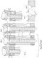
- In Fig. 1
- ist eine übliche, zum Stand der Technik gehörende Rundkopfknochenschraube zur Verwendung mit einer Osteosyntheseplatte 1 dargestellt, die
einen Knochengewindeabschnitt 2, einen gerundeten Schraubenkopf 3 und eine in den Schraubenkopf hineinreichende imbusartige Handhabe 4 aufweist. Der gerundete Schraubenkopf liegt in einem in Komplementärform ausgestalteten Schraubenloch 5 der Osteosynthesplatte; die Schraube durchsetzt mit ihrem Knochengewindeabschnitt die anliegende Knochenrinde 6, den spongiösen Markraum 7 und die gegenüberliegende zweite Knochenrinde 8. Als punktierte Linie 9 ist der für Schraubenbrüche kritische Bereich im zweiten Gewindegang gekennzeichnet, in dem es meist zum Bruch kommt. - In Fig. 2
- ist ein Teil der Knochenschraube nach Fig. 1 mit etwas abgehobener Osteosyntheseplatte und den anliegenden Knochenabschnitten nach Schraubenbruch dargestellt.
Mit 10 ist die Bruchkante des mit dem Schraubenkopf zusammenhängenden Segmentes,mit 11 die Bruchkante desim Knochen 12 verbleibenden Schraubenteils bezeichnet; das im Knochen liegende Schraubensegment überragt die Knochenoberfläche 13 kaum und kann daher nicht gefaßt werden. - In Fig. 3
- ist ein Ausführungsbeispiel der erfindungsgemäßen Rundkopfknochenschraube dargestellt, wobei die
mit den Zahlen 1, 2, 3, 5, 6, 7 und 8 bezeichneten Bereichen den Verhältnissen in Fig. 1 entsprechen.Mit 14 ist der gewindelose und sich konisch verstärkende Abschnitt der Knochenschraube dargestellt, der außerhalb des Knochens liegt und in das Schraubenloch hineinragt.Mit 15 ist ein erstes Segment der imbus-artigen Handhabe 15 bezeichnet, das im Querdurchmesser und in seiner Längsausgestaltung vergrößert und dem Angriff eines Schraubenziehers dient.Mit 16 ist ein zweites imbusartiges Segment der Handhabe bezeichnet, das konisch gestaltet ist und an seinem Übergang zum erstenSegment 15 die Sollbruchstelle 17 darstellende Materialschwächung ausbildet. - In Fig. 4
- ist ein Teil der Knochenschraube nach Fig. 3 mit etwas abgehobener Platte und den anliegenden Knochenabschnitten nach Schraubenbruch dargestellt.
Mit 17 ist die Bruchkante im Schraubenkopf bezeichnet;das erste Segment 15 der imbus-artigen Handhabe stellt nun einen durchgehenden Kanal dar.Mit 18 ist die Bruchkante des in den Knochen hineinragenden Schraubenteils bezeichnet, die das in diesem Schraubenabschnitt verbleibende zweite imbusartige Handhabe-Segment 16 umgibt. Durch Eingriff eines Betätigungswerkzeuges, wie eines Schraubenziehers, in dieses zweite Handhabesegment kann nun auch eine abgebrochende Schraube mühelos entfernt werden. Außerdemragt ein Abschnitt 19 der abgebrochenen Schraube soweit über dieKnochenoberfläche 20 hinaus, daß dieses Segment auch mit einem Betätigungswerkzeug, wie z.B. einer Zange zum Zwecke der Entfernung gefaßt werden kann. - In Fig. 5
ist ein Osteosynthesenplattensegment 21 mit einem kugelsegmentartigem Rundloch 22 für den Schraubenkopf dargestellt, das bei 23 in den zylindrischen Durchsetzungsabschnitt 24 übergeht.Der Öffnungswinkel 25 beschreibt den Öffnungswinkel im Querschnittsbild, der den Übergang vom kugelsegmentartigen Auflagebereich für den Schraubenkopf zum Durchsetzungsbereich 24 charakterisiert, im dem der verstärkte Schraubenschaft liegt. Damit bei Biege- und Scherbelastungen keine den schraubenkopfabseitigen Abschnitt des Verstärkungsbereichs überlastenden Biegemomente auftreten, muß der Öffnungswinkel 25 über einem bestimmten Minimalbetrag liegen. Dadurch kann vermieden werden, daß durch ungünstig einwirkende Biegemomente auf den Verstärkungsbereich des Schraubenschaftes ein Bruch nahe der Knochenoberfläche auftritt. Durch die Vergrößerung des Öffnungswinkels kann durch die abgestimmte Schwächung des kritischen Schraubenlochbereichs hier eine Sollbruchstelle für das Gesamtimplantat eingerichtet werden.- Fig. 6
- zeigt eine gebrochene Schraube aus dem Stand der Technik zur Wirbelsäulenfixation, die aus einer ein
Maschinengewinde aufweisenden Ankopplungseinrichtung 26,einem Knochengewindeabschnitt 27 und einer den Knochengewindeabschnitt imDurchmesser überragenden Handhabe 28 besteht. Aufgrund der geometrischen Verhältnisse kommt es bei Überlastungen zumBruch im Knochengewindebereich 29, wobei dann das im Knochen liegende Schraubensegment keine Handhabe für den Angriff eines Betätigungswerkzeuges mehr aufweist und dieser Abschnitt, da im Knochen liegend, auch ohne Knochenresektion nicht gefaßt werden kann. - Fig. 7
- zeigt ein erfindungsgemäßes Ausführungsbeispiel einer Schraube für die Wirbelsäulenfixation, die wiederum einen Abschnitt 30 mit Maschinengewinde,
eine Handhabe 31 und einen Knochengewindebereich 32 aufweist. Dieser Knochengewindebereich besteht aus einem ersten zylindrischen Abschnitt 33 und einem nicht-zylindrischen Verstärkungsbereich 34, der z.B. eine konische Außen- und Kernform aufweisen kann. An die Handhabe schließt auf der knochengewindeabseitigen Seiteein Bereich 35 an, in dem die Sollbruchstelle durch Querschnittsreduzierung ausgebildet ist. Am knochengewindeabseitigen Ende der Schraube ist eine zweite Handhabe 36 eingerichtet, über die eine Mutter 37auf den Maschinengewindeabschnitt 30 verbracht werden kann. Das Innengewinde der Mutter 37 und/oder Außengewinde 30 des Schraubenschaftes können mit einem ein selbsttätiges Losdrehen verhinderndes Lockgewindeprofil ausgestattet sein. - Fig. 8
- stellt ein Segment einer anderen Ausführungsform der in den Schraubenschaft integrierten Ankopplungseinrichtung dar, die sich
mit ihrem Schaft 38 an das knochengewindeabseitige Ende des Sollbruchsabschnitts anschließt. An ihrem anderen Ende befindet sich eine mit einer gerasterten Oberfläche ausgestattete Anlagerungsfläche 39, die mittels einer Schraube, die indie Gewindeöffnung 40 eingreift, auf eine zweite, ebenfalls gerasterte Scheibe angepreßt wird, wobei letztere in einen Lastträger integriert sein kann. - In Fig. 9
- ist ein Segment einer zur Wirbelsäulenfixation geeigneten Schraube 41 dargestellt, auf deren ein
Maschinengewinde enthaltenden Ankopplungseinrichtung 42eine zweiteilige Klammer 43/44 aufgeschoben ist.Das Klammersegment 43 weist an seiner Stirnseite eine sechskantige Öffnung 45 auf, in eine ebenfalls sechskantige Handhabe 46 rotationssicher einrasten kann.Wenn die Klammersegmente 43/44 mittels einer nachfolgenden Mutter 37 gegen dieStirnwand 47 des Verstärkungsbereichs, an die die Handhabe anschließt, angepreßt wird, kann eine rotationssichere Verbindung zu einem indie Hohlkehlen 48/49 der beiden Klammersegmenten eingelagerten, stabförmigen Lastträger geschaffen werden.Die Stirnwand 47 wie auch dieHohlkehlen 48/49 können eine gerillte, gerasterte, geriffelte oder aufgerauhte Oberflächenstruktur aufweisen, umso eine rotationssichere Verbindung mit den angelagerten Fixationselementen sicherzustellen. Am Ober- und/oder Unterrand 50 der Hohlkehlen einer oder beider Klammersegmente kann eine prominente Schneidkante eingearbeitet sein, die bei erfolgter Endmontage in die prominenten Oberflächenstrukturen eines stabförmigen Lastträgers eindringt und so eine ungewollte Längsverschiebung der Klammer auf dem stabförmigen Lastträger verhindert. Diese einer Einkerbung vergleichbare Einformung kann bei Überlastungssituationen wie eine Sollbruchstelle wirken, sodaß durch Bruch an dieser Stelle, Brüche der in den Knochen hineinreichenden Fixationsmittel vermieden werden können. - Fig. 10
- stellt einen stabförmigen Lastträger dar, der eine zylindrische Gestalt aufweist und an dem mittels einer segmentalen Querschnittsreduzierung 51 eine Sollbruchstelle ausgebildet ist.
An seiner Außenseite des Schaftes 52 weist der Lastträger eine Längsrillung 53 auf, die mit der gerillten Oberfläche der Hohlkehlen 48/49 der zweiteiligen Klammer in Fig. 9 in Kontakt tritt. - Fig. 11
- zeigt schematisch die Gewindeausbildung von drei unterschiedliche Außen- und Kerndurchmesser aufweisenden Knochenschraubenteilen. Die verschiedenen Knochenschraubenteile sind dabei mit K1, 2 und K3 bezeichnet. Die Gewindesteigung ist mit dem Zeichen h versehen, der Außendurchmesser mit dem Zeichen d, der Kerndurchmesser mit dem Zeichen dk und die Gewindetiefe mit dem Zeichen gt.
Die Gewindegänge der drei Teilschrauben sind übereinander dargestellt und in der Zeichnung sind die Gewindescheitel der drei Teilschrauben K1, K2 und K3 durch eine Verbindungslinie V verbunden. Diese Verbindungslinie liegt auf der Winkelhalbierenden der Gewindegänge der drei Schrauben.
Die ersten Gewindegänge einer Größe sind dem Aussendurchmesser der nächstkleineren Nenngröße angenähert und steigen dann zum Durchmesser der eigenen Nenngröße an.
Durch eine solche Ausgestaltung wird erreicht, daß bei Anwenden größenmäßig aufeinanderfolgender Gewindbohrer bzw. Knochenschrauben ein Verletzen der vorher vorhandenen Gewindegänge vermieden wird.
- In Fig. 1
- A conventional round-head bone screw belonging to the state of the art is shown for use with an osteosynthesis plate 1, which has a
bone thread section 2, a rounded screw head 3 and an Allen key-like handle 4 which extends into the screw head. The rounded screw head lies in a complementary screw hole 5 of the osteosynthesis plate; the screw with its bone thread section penetrates the adjacent bone cortex 6, the cancellous medullary cavity 7 and the opposite second bone cortex 8. The dotted line 9 denotes the area in the second thread turn which is critical for screw breaks and in which breakage usually occurs. - In Fig. 2
- part of the bone screw according to FIG. 1 is shown with the osteosynthesis plate slightly lifted off and the adjacent bone sections after the screw has broken. The breaking edge of the segment connected to the screw head is designated by 10, and the breaking edge of the screw part remaining in the
bone 12 is designated by 11; the screw segment lying in the bone hardly protrudes beyond the bone surface 13 and can therefore not be grasped. - 3
- An embodiment of the round-head bone screw according to the invention is shown, the areas designated by the
numbers 1, 2, 3, 5, 6, 7 and 8 corresponding to the relationships in FIG. 1. 14 shows the threadless and conically reinforcing section of the bone screw, which lies outside the bone and protrudes into the screw hole. 15 designates a first segment of the Allen-type handle 15, which is enlarged in the transverse diameter and in its longitudinal configuration and serves to attack a screwdriver. 16 denotes a second hex-like segment of the handle, which is conical in shape and at its transition to thefirst segment 15 forms the weakening of the material representing thepredetermined breaking point 17. - 4
- 3 shows a part of the bone screw according to FIG. 3 with the plate slightly lifted off and the adjacent bone sections after the screw has broken. The breaking edge in the screw head is denoted by 17; the
first segment 15 of the hex-type handle now represents a continuous channel. 18 denotes the breaking edge of the screw part protruding into the bone, which surrounds the second hex-type handle segment 16 remaining in this screw section. By engaging an actuating tool, such as a screwdriver, in this second handling segment, a broken-off screw can now be easily removed. In addition, asection 19 of the broken screw projects so far beyond thebone surface 20 that this segment also can be gripped with an operating tool such as pliers for the purpose of removal. - 5
- an
osteosynthesis plate segment 21 is shown with a spherical segment-likeround hole 22 for the screw head, which merges at 23 into the cylindrical enforcement section 24. Theopening angle 25 describes the opening angle in the cross-sectional image, which characterizes the transition from the spherical segment-like contact area for the screw head to the enforcement area 24 in which the reinforced screw shaft lies. Theopening angle 25 must be above a certain minimum amount so that no bending moments which overload the screw head-side section of the reinforcement area occur under bending and shear loads. It can thereby be avoided that a breakage near the bone surface occurs due to unfavorable bending moments on the reinforcement area of the screw shaft. By increasing the opening angle, a predetermined breaking point for the entire implant can be established here through the coordinated weakening of the critical screw hole area. - Fig. 6
- shows a broken screw from the prior art for spinal fixation, which consists of a
coupling device 26 having a machine thread, abone thread section 27 and ahandle 28 projecting beyond the diameter of the bone thread section. Due to the geometrical conditions, there is a break in thebone thread region 29 in the event of overloads, the screw segment lying in the bone then no longer having any handle for the attack of an actuating tool and this section, because it lies in the bone, cannot be grasped even without bone resection. - Fig. 7
- shows an embodiment of a screw according to the invention for spinal fixation, which in turn has a
section 30 with a machine thread, ahandle 31 and abone thread region 32. This Bone thread area consists of a firstcylindrical section 33 and anon-cylindrical reinforcement area 34, which can have, for example, a conical outer and core shape. Anarea 35 adjoins the handle on the side on the bone thread side, in which the predetermined breaking point is formed by reducing the cross section. At the end of the screw on the bone thread side, asecond handle 36 is set up, by means of which a nut 37 can be placed on themachine thread section 30. The internal thread of the nut 37 and / orexternal thread 30 of the screw shaft can be equipped with a lock thread profile which prevents it from loosening automatically. - Fig. 8
- represents a segment of another embodiment of the coupling device integrated in the screw shaft, which connects with its
shaft 38 to the end of the predetermined breaking section away from the bone thread. At its other end there is a bearingsurface 39 equipped with a rastered surface, which is pressed onto a second, also rasterized disc by means of a screw which engages in the threadedopening 40, the latter being able to be integrated in a load carrier. - In Fig. 9
- A segment of a
screw 41 suitable for spinal fixation is shown, on thecoupling device 42 containing a machine thread, a two-part clamp 43/44 is pushed onto it. Theclamp segment 43 has ahexagonal opening 45 on its end face, into which ahexagonal handle 46 can also engage in a rotationally secure manner. If theclamp segments 43/44 are pressed against theend wall 47 of the reinforcement region to which the handle is connected by means of a subsequent nut 37, a rotationally secure connection to a rod-shaped load carrier embedded in thegrooves 48/49 of the two clamp segments can be created. Theend wall 47 as well as thegrooves 48/49 can be a grooved, gridded, have corrugated or roughened surface structure in order to ensure a rotation-proof connection with the attached fixation elements. A prominent cutting edge can be incorporated on the upper and / orlower edge 50 of the fillets of one or both clamp segments, which penetrates into the prominent surface structures of a rod-shaped load carrier when final assembly is carried out and thus prevents an undesired longitudinal displacement of the clamp on the rod-shaped load carrier. This indentation, which is comparable to a notch, can act as a predetermined breaking point in overload situations, so that breakage of the fixation means reaching into the bone can be avoided by breaking at this point. - Fig. 10
- represents a rod-shaped load carrier, which has a cylindrical shape and on which a predetermined breaking point is formed by means of a
segmental cross-section reduction 51.
On its outside of theshaft 52, the load carrier has alongitudinal groove 53 which comes into contact with the grooved surface of thegrooves 48/49 of the two-part clamp in FIG. 9. - Fig. 11
- shows schematically the thread formation of three different external and core diameter bone screw parts. The various bone screw parts are designated K 1 , 2 and K 3 . The thread pitch is marked with the symbol h, the outer diameter with the symbol d, the core diameter with the symbol d k and the thread depth with the symbol gt.
The threads of the three partial screws are shown one above the other and in the drawing the thread crests of the three partial screws K 1 , K 2 and K 3 are connected by a connecting line V. This connecting line lies on the bisector of the thread of the three screws.
The first threads of a size are the outside diameter approximates the next smaller nominal size and then increases to the diameter of your own nominal size.
Such a configuration ensures that when using successively sized drill bits or bone screws, injury to the previously existing thread turns is avoided.
Claims (28)
- A load transfer member for osteosynthesis in the form of an operating instrument engaging in the bone only during an operation, such as a bone tap, a thread cutter, a flexible shaft or a milling cutter, consisting of a shank connecting non-positively with the bone and a device for coupling to other osteosynthetic aids, wherein the load transfer member comprises a predetermined breaking point located when in use between the coupling device and the bone and lying outside the bone mass and, in the case of breakage of the load transfer member at the predetermined breaking point, comprises a segment projecting beyond the bone surface and permitting direct engagement of an actuating tool.
- An implantable load transfer member for osteosynthesis, consisting of a shank (2, 21, 33, 52) connecting nonpositively with the bone and a device (3, 22, 39, 38, 42, 44, 53) for coupling to other osteosynthetic aids, characterised in that the load transfer member comprises a predetermined breaking point (17, 22, 35, 51) located, when in use and after its attachment in or on the bone, between the coupling device and the bone and lying outside the bone mass and, in the case of breakage of the load transfer member at the predetermined breaking point, comprises a segment (19, 31, 52) projecting beyond the bone surface and permitting direct engagement of an actuating tool.
- A load transfer member according to claim 2, characterised in that at least part of the shank is constructed as a fixing means engaging in the bone, such as a bone pin, a thread-bearing member, a bone screw (32), a screw insert, nail, wire or prosthesis component.
- A load transfer member according to claim 2, characterised in that the shank is part of an osteosynthetic implant located outside the bone or lying thereon, such as a bone plate (21), a rod (52), a tube, a wire or a clip.
- A load transfer member according to any one of the preceding claims, characterised in that at least a first handling element (15, 31) is formed for an actuating tool.
- A load transfer member according to claim 5, characterised in that the handling element comprises an end face (47) suitable for the exertion of pressure.
- A load transfer member according to claim 5 or claim 6, characterised in that a second handling element (16, 36) is formed for an actuating tool.
- A load transfer member according to any one of claims 5 to 7, characterised in that at least one handling element has a cross section (31) deviating from the purely circular and a load transfer and driving segment.
- A load transfer member according to claim 8, characterised in that at least one handling element comprises two driving segments (15, 16).
- A load transfer member according to claim 9, characterised in that at least one driving segment is conical or spherical in form.
- A load transfer member according to any one of the preceding claims, characterised in that the predetermined breaking point is formed by material weakening, such as notching, segmental cross-sectional reduction (35) or constriction (17).
- A load transfer member according to claim 2 or any of the preceding claims dependent on claim 2, characterised in that the predetermined breaking point is formed by cross-sectional undersizing in a load transfer member located outside the bone and acting as an implant component (52).
- A load transfer member according to claim 2 or any one of the preceding claims dependent on claim 2, said member forming, with other load transfer components, an implant system composed of several components, characterised in that an implant component comprises a prominent edge (50) in the contact area, which edge (50) has a notching effect on the shank of the load transfer member (53) during assembly and thereby generates a predetermined breaking point on the load transfer member.
- A load transfer member according to claim 4, in which the shank is constructed as part of an osteosynthetic plate and comprises at least one screw hole, which opens into a passage portion (24) in a transition area (23), the line normal to the tangents on the faces of the screw hole in the transition area (23) forming an angle alpha (25) opening in the passage area, characterised in that the predetermined breaking point is located in the area of the screw hole and the aperture angle alpha (25) is larger than 75°.
- A load transfer member according to claims 3 and 5 or any one of the preceding claims dependent on these claims, characterised in that the predetermined breaking point is formed between the bone thread portion and the coupling device in such a way that, when the thread-bearing member breaks in the area of the predetermined breaking point, at least one operative segment (16) of the handling element remains on the bone thread segment.
- A load transfer member according to claims 3 and 5 or any one of the preceding claims dependent on these claims, characterised in that the shank is threaded at least over a portion thereof and comprises a widened area (14, 34) at the transition point from the bone thread portion to the handling element.
- A load transfer member according to claim 16, characterised in that the widened area has an outer contour deviating from the cylindrical, for example conical (34), spherical or spheroidal.
- A load transfer member according to claim 16 or claim 17, characterised in that the widened area is characterised by an increase in the cross section of the outer and/or core diameter.
- A load transfer member according to claims 3, 5 and 16 or any one of the preceding claims dependent on these claims, characterised in that a segment (16) of the handling element extends into the widened area (14).
- A load transfer member according to claims 3 and 16 or any one of the preceding claims dependent on these claims, characterised in that a handling element (31) is positioned between the widened area and the coupling device.
- A load transfer member according to any one of the preceding claims, characterised in that a handling element is at least part of the coupling device.
- A load transfer member according to any one of the preceding claims, characterised in that part of the coupling device (47, 48, 49) comprises a profiled engagement surface, such as, for example, a grooved, textured or corrugated surface.
- A load transfer member according to any one of the preceding claims, characterised in that the coupling device comprises an inner and/or outer threaded portion (30, 40) and at least one of the threads integral with the coupling area comprises a self-locking thread profile.
- A set of load transfer members according to any one of the preceding claims, characterised in that the load transfer members have bone threads and each load transfer member of the set has the same pitch (h) even when the nominal diameter (d) varies.
- A set of load transfer members according to any one of the preceding claims, characterised in that the load transfer members have bone threads and each load transfer member of the set has the same pitch (h) even when the core diameters (dk) vary.
- A set of load transfer members according to any one of the preceding claims, characterised in that the load transfer members have bone threads and each load transfer member of the set has the same pitch (h) even when the thread depth (gt) varies.
- A set of load transfer members according to any one of claims 24 to 26, characterised in that each set is composed at least of one operating instrument, such as a tap for example, and a bone implant adaptable in size thereto, such as a bone screw for example.
- A set of load transfer members according to claim 27, characterised in that the outer and/or core diameters of the bone implants are from 0.5 to 1.0 mm over the corresponding diameters of the operating instruments.
Applications Claiming Priority (2)
| Application Number | Priority Date | Filing Date | Title |
|---|---|---|---|
| DE4339804 | 1993-11-23 | ||
| DE4339804A DE4339804A1 (en) | 1993-11-23 | 1993-11-23 | Power transmission link for osteosynthesis work |
Publications (2)
| Publication Number | Publication Date |
|---|---|
| EP0654248A1 EP0654248A1 (en) | 1995-05-24 |
| EP0654248B1 true EP0654248B1 (en) | 1997-04-02 |
Family
ID=6503173
Family Applications (1)
| Application Number | Title | Priority Date | Filing Date |
|---|---|---|---|
| EP94118281A Expired - Lifetime EP0654248B1 (en) | 1993-11-23 | 1994-11-21 | Load transfer member for osteosynthesis |
Country Status (5)
| Country | Link |
|---|---|
| US (1) | US5653710A (en) |
| EP (1) | EP0654248B1 (en) |
| AT (1) | ATE150956T1 (en) |
| DE (2) | DE4339804A1 (en) |
| ES (1) | ES2102123T3 (en) |
Families Citing this family (86)
| Publication number | Priority date | Publication date | Assignee | Title |
|---|---|---|---|---|
| US6193719B1 (en) | 1995-08-24 | 2001-02-27 | Sofamor S.N.C. | Threaded clamping plug for interconnecting two implants of a spinal osteosynthesis instrumentation or other implants |
| US5888200A (en) * | 1996-08-02 | 1999-03-30 | Stryker Corporation | Multi-purpose surgical tool system |
| US6224596B1 (en) | 1997-01-06 | 2001-05-01 | Roger P. Jackson | Set screw for use with osteosynthesis apparatus |
| US6004349A (en) | 1997-01-06 | 1999-12-21 | Jackson; Roger P. | Set screw for use with osteosynthesis apparatus |
| FR2763832B1 (en) * | 1997-05-29 | 1999-10-01 | Materiel Orthopedique En Abreg | VERTEBRAL ROD FOR INSTRUMENTATION OF RACHIDIAN OSTEOSYNTHESIS, AND OSTEOSYNTHESIS INSTRUMENTATION COMPRISING SUCH ROD |
| US5899902A (en) * | 1997-07-03 | 1999-05-04 | Depuy Motech Acromed Corporation | Fastener |
| US6325803B1 (en) | 1998-02-18 | 2001-12-04 | Walter Lorenz Surgical, Inc. | Method and apparatus for mandibular osteosynthesis |
| US7052499B2 (en) * | 1998-02-18 | 2006-05-30 | Walter Lorenz Surgical, Inc. | Method and apparatus for bone fracture fixation |
| US6129728A (en) * | 1998-02-18 | 2000-10-10 | Walter Lorenz Surgical, Inc. | Method and apparatus for mandibular osteosynthesis |
| US6056753A (en) * | 1998-07-13 | 2000-05-02 | Jackson; Roger P. | Set screw for use with osteosynthesis apparatus |
| GB9816962D0 (en) * | 1998-08-04 | 1998-09-30 | Dall Vagn E | Lockable screw assembly |
| US5971987A (en) * | 1998-09-18 | 1999-10-26 | Ethicon, Inc. | Biocompatible absorbable polymer fastener and driver for use in surgical procedures |
| US6059786A (en) * | 1998-10-22 | 2000-05-09 | Jackson; Roger P. | Set screw for medical implants |
| US6355043B1 (en) * | 1999-03-01 | 2002-03-12 | Sulzer Orthopedics Ltd. | Bone screw for anchoring a marrow nail |
| EP1042988B1 (en) * | 1999-04-08 | 2008-01-02 | ORTHOFIX S.r.l. | Bone screw for external fixators |
| US6423067B1 (en) | 1999-04-29 | 2002-07-23 | Theken Surgical Llc | Nonlinear lag screw with captive driving device |
| EP1101448B1 (en) * | 1999-11-17 | 2007-04-25 | The University of Hong Kong | Anterior transpedicular fixation system for maintaining a vertebral column |
| US6235028B1 (en) | 2000-02-14 | 2001-05-22 | Sdgi Holdings, Inc. | Surgical guide rod |
| US6565566B1 (en) | 2000-03-22 | 2003-05-20 | Spinal Concepts, Inc. | Sacral screw assembly and method |
| MXPA02012919A (en) * | 2000-07-28 | 2003-09-22 | Synthes Ag | Spinal fixation system. |
| US7833250B2 (en) | 2004-11-10 | 2010-11-16 | Jackson Roger P | Polyaxial bone screw with helically wound capture connection |
| FR2816196B1 (en) * | 2000-11-07 | 2003-01-03 | Medicrea | VERTEBRAL ARTHRODESIS MATERIAL |
| US6454768B1 (en) | 2000-12-05 | 2002-09-24 | Roger P. Jackson | Removable gripping set screw |
| US6997927B2 (en) * | 2000-12-08 | 2006-02-14 | Jackson Roger P | closure for rod receiving orthopedic implant having a pair of spaced apertures for removal |
| US6454772B1 (en) | 2000-12-08 | 2002-09-24 | Roger P. Jackson | Set screw for medical implant with gripping side slots |
| US6726687B2 (en) * | 2000-12-08 | 2004-04-27 | Jackson Roger P | Closure plug for open-headed medical implant |
| US6726689B2 (en) | 2002-09-06 | 2004-04-27 | Roger P. Jackson | Helical interlocking mating guide and advancement structure |
| US8377100B2 (en) | 2000-12-08 | 2013-02-19 | Roger P. Jackson | Closure for open-headed medical implant |
| FR2821131B1 (en) * | 2001-02-22 | 2003-12-12 | Spine Next Sa | FASTENING SCREW |
| US7235079B2 (en) * | 2004-11-18 | 2007-06-26 | Acumed Llc | Composite bone fasteners |
| US6953463B2 (en) * | 2001-10-12 | 2005-10-11 | Hs West Investments, Llc | Interference screws having increased proximal diameter |
| US6783527B2 (en) | 2001-10-30 | 2004-08-31 | Sdgi Holdings, Inc. | Flexible spinal stabilization system and method |
| US6875215B2 (en) * | 2002-02-15 | 2005-04-05 | John Stanley Taras | Distraction pin for fracture fixation |
| US20050065521A1 (en) * | 2002-02-22 | 2005-03-24 | Steger Shon D. | Method and apparatus for bone fracture fixation |
| US7001389B1 (en) | 2002-07-05 | 2006-02-21 | Navarro Richard R | Fixed and variable locking fixation assembly |
| US8876868B2 (en) | 2002-09-06 | 2014-11-04 | Roger P. Jackson | Helical guide and advancement flange with radially loaded lip |
| US8257402B2 (en) | 2002-09-06 | 2012-09-04 | Jackson Roger P | Closure for rod receiving orthopedic implant having left handed thread removal |
| US8282673B2 (en) | 2002-09-06 | 2012-10-09 | Jackson Roger P | Anti-splay medical implant closure with multi-surface removal aperture |
| US7517350B2 (en) * | 2002-11-20 | 2009-04-14 | Orthopediatrics Corp. | Convertible threaded compression device and method of use |
| US7235078B2 (en) * | 2002-11-26 | 2007-06-26 | Hs West Investments Llc | Protective devices for use with angled interference screws |
| JP2006514233A (en) * | 2003-02-12 | 2006-04-27 | ジンテーズ アクチエンゲゼルシャフト クール | Screw with integral screwdriver |
| US7461574B2 (en) * | 2003-04-28 | 2008-12-09 | Biomet Microfixation, Llc | Multiple screw delivery apparatus |
| US7354442B2 (en) * | 2003-05-05 | 2008-04-08 | Warsaw Orthopedic, Inc. | Bone anchor and methods of using the same |
| US7377923B2 (en) | 2003-05-22 | 2008-05-27 | Alphatec Spine, Inc. | Variable angle spinal screw assembly |
| US8137386B2 (en) | 2003-08-28 | 2012-03-20 | Jackson Roger P | Polyaxial bone screw apparatus |
| US7967850B2 (en) | 2003-06-18 | 2011-06-28 | Jackson Roger P | Polyaxial bone anchor with helical capture connection, insert and dual locking assembly |
| US8398682B2 (en) | 2003-06-18 | 2013-03-19 | Roger P. Jackson | Polyaxial bone screw assembly |
| US7776067B2 (en) | 2005-05-27 | 2010-08-17 | Jackson Roger P | Polyaxial bone screw with shank articulation pressure insert and method |
| US8366753B2 (en) | 2003-06-18 | 2013-02-05 | Jackson Roger P | Polyaxial bone screw assembly with fixed retaining structure |
| US8936623B2 (en) | 2003-06-18 | 2015-01-20 | Roger P. Jackson | Polyaxial bone screw assembly |
| US7766915B2 (en) | 2004-02-27 | 2010-08-03 | Jackson Roger P | Dynamic fixation assemblies with inner core and outer coil-like member |
| US7468064B2 (en) * | 2003-08-21 | 2008-12-23 | Warsaw Orthopedic, Inc. | Systems and methods for positioning implants relative to bone anchors in surgical approaches to the spine |
| EP1811911A4 (en) | 2004-11-10 | 2012-01-11 | Roger P Jackson | Helical guide and advancement flange with break-off extensions |
| US8926672B2 (en) | 2004-11-10 | 2015-01-06 | Roger P. Jackson | Splay control closure for open bone anchor |
| US9168069B2 (en) | 2009-06-15 | 2015-10-27 | Roger P. Jackson | Polyaxial bone anchor with pop-on shank and winged insert with lower skirt for engaging a friction fit retainer |
| US10076361B2 (en) | 2005-02-22 | 2018-09-18 | Roger P. Jackson | Polyaxial bone screw with spherical capture, compression and alignment and retention structures |
| US20070270859A1 (en) * | 2006-04-28 | 2007-11-22 | Sdgi Holdings, Inc. | Orthopedic screw with break away drive |
| US9827023B2 (en) | 2007-01-29 | 2017-11-28 | Life Spine, Inc. | Craniospinal fusion method and apparatus |
| US20090036894A1 (en) * | 2007-01-29 | 2009-02-05 | Polaris Biotechnology, Inc. | Method of treating a neurological condition through correction and stabilization of the clivo-axial angle |
| US8083743B2 (en) * | 2007-01-29 | 2011-12-27 | Polaris Biotechnology, Inc. | Craniospinal fusion method and apparatus |
| US8556939B2 (en) * | 2008-01-08 | 2013-10-15 | Fraser Cummins Henderson | Mathematical relationship of strain, neurological dysfunction and abnormal behavior resulting from neurological dysfunction of the brainstem |
| US8403965B2 (en) * | 2007-01-29 | 2013-03-26 | Polaris Biotechnology, Inc. | Vertebra attachment method and system |
| US8182511B2 (en) * | 2007-01-29 | 2012-05-22 | Polaris Biotechnology, Inc. | Craniospinal fusion method and apparatus |
| WO2008112831A1 (en) * | 2007-03-12 | 2008-09-18 | Arya Nick Shamie | Improved cervical support system |
| EP2177051B1 (en) | 2007-07-20 | 2015-06-17 | Cochlear Americas | Bone anchor fixture for a medical prosthesis |
| EP2249728A4 (en) * | 2008-01-08 | 2012-12-12 | Polaris Biotechnology Inc | Osteointegration apparatus |
| FR2941859B1 (en) | 2009-02-09 | 2012-04-06 | Memometal Technologies | OSTEOSYNTHESIS SCREW. |
| CN103917181A (en) | 2009-06-15 | 2014-07-09 | 罗杰.P.杰克逊 | Polyaxial bone anchor with pop-on shank and friction fit retainer with low profile edge lock |
| US11229457B2 (en) | 2009-06-15 | 2022-01-25 | Roger P. Jackson | Pivotal bone anchor assembly with insert tool deployment |
| DE102009032034A1 (en) | 2009-06-26 | 2010-12-30 | Aesculap Ag | Surgical bone anchoring device and spine fixation system |
| US8523914B2 (en) * | 2010-01-28 | 2013-09-03 | Warsaw Orthopedic, Inc. | Bone anchor with predetermined break point and removal features |
| ES2469872T3 (en) * | 2010-05-07 | 2014-06-20 | Klaus Pastl | Bone screw |
| US20120214127A1 (en) * | 2011-02-22 | 2012-08-23 | Warsaw Orthopedic, Inc. | Dental implant system with separable drive and method |
| US8956361B2 (en) | 2011-12-19 | 2015-02-17 | Amendia, Inc. | Extended tab bone screw system |
| US8911479B2 (en) | 2012-01-10 | 2014-12-16 | Roger P. Jackson | Multi-start closures for open implants |
| US8911478B2 (en) | 2012-11-21 | 2014-12-16 | Roger P. Jackson | Splay control closure for open bone anchor |
| US10058354B2 (en) | 2013-01-28 | 2018-08-28 | Roger P. Jackson | Pivotal bone anchor assembly with frictional shank head seating surfaces |
| US8852239B2 (en) | 2013-02-15 | 2014-10-07 | Roger P Jackson | Sagittal angle screw with integral shank and receiver |
| WO2014144570A2 (en) * | 2013-03-15 | 2014-09-18 | Medsmart Innovation, Inc. | Dynamic spinal segment replacement |
| US9566092B2 (en) | 2013-10-29 | 2017-02-14 | Roger P. Jackson | Cervical bone anchor with collet retainer and outer locking sleeve |
| US9717533B2 (en) | 2013-12-12 | 2017-08-01 | Roger P. Jackson | Bone anchor closure pivot-splay control flange form guide and advancement structure |
| US9451993B2 (en) | 2014-01-09 | 2016-09-27 | Roger P. Jackson | Bi-radial pop-on cervical bone anchor |
| US11240613B2 (en) | 2014-01-30 | 2022-02-01 | Cochlear Limited | Bone conduction implant |
| FR3019981B1 (en) * | 2014-04-17 | 2020-12-11 | Medicrea Int | VERTEBRAL OSTEOSYNTHESIS MATERIAL |
| US10064658B2 (en) | 2014-06-04 | 2018-09-04 | Roger P. Jackson | Polyaxial bone anchor with insert guides |
| US9597119B2 (en) | 2014-06-04 | 2017-03-21 | Roger P. Jackson | Polyaxial bone anchor with polymer sleeve |
Family Cites Families (8)
| Publication number | Priority date | Publication date | Assignee | Title |
|---|---|---|---|---|
| DE3630863A1 (en) * | 1986-09-08 | 1988-03-17 | Mecron Med Prod Gmbh | Bone screw |
| DE3800052A1 (en) * | 1987-07-08 | 1989-07-13 | Harms Juergen | POSITIONING SCREW |
| CH681957A5 (en) * | 1988-11-17 | 1993-06-30 | Synthes Ag | |
| US5129900B1 (en) * | 1990-07-24 | 1998-12-29 | Acromed Corp | Spinal column retaining method and apparatus |
| DE4026777A1 (en) * | 1990-08-24 | 1992-03-05 | Haerle Anton | FOCUS BONE SCREW AND / OR TAP FOR OSTEOSYNTHESIS WORK |
| US5085660A (en) * | 1990-11-19 | 1992-02-04 | Lin Kwan C | Innovative locking plate system |
| CH686339A5 (en) * | 1991-12-10 | 1996-03-15 | Synthes Ag | Nut for the plate fixation. |
| DE9303828U1 (en) * | 1993-03-11 | 1993-06-24 | Aap Gmbh & Co. Betriebs Kg, 1000 Berlin, De |
-
1993
- 1993-11-23 DE DE4339804A patent/DE4339804A1/en not_active Withdrawn
-
1994
- 1994-11-21 DE DE59402294T patent/DE59402294D1/en not_active Expired - Lifetime
- 1994-11-21 ES ES94118281T patent/ES2102123T3/en not_active Expired - Lifetime
- 1994-11-21 US US08/342,499 patent/US5653710A/en not_active Expired - Fee Related
- 1994-11-21 AT AT94118281T patent/ATE150956T1/en not_active IP Right Cessation
- 1994-11-21 EP EP94118281A patent/EP0654248B1/en not_active Expired - Lifetime
Also Published As
| Publication number | Publication date |
|---|---|
| DE59402294D1 (en) | 1997-05-07 |
| ES2102123T3 (en) | 1997-07-16 |
| EP0654248A1 (en) | 1995-05-24 |
| DE4339804A1 (en) | 1995-06-01 |
| ATE150956T1 (en) | 1997-04-15 |
| US5653710A (en) | 1997-08-05 |
Similar Documents
| Publication | Publication Date | Title |
|---|---|---|
| EP0654248B1 (en) | Load transfer member for osteosynthesis | |
| EP1096892B1 (en) | Osteosynthesis screw, especially for application by a translaminar vertebral screw | |
| DE3701765C1 (en) | Bone screw | |
| DE60206700T2 (en) | Fastening device for bone parts | |
| EP1430846B1 (en) | Bone screw for spinal or orthopaedic surgery | |
| EP1472983B1 (en) | Threaded bone anchoring element for unscrewing | |
| EP0172130B1 (en) | Screw for orthopaedic fixation | |
| EP1940306B1 (en) | Thread-forming screw | |
| DE19951760B4 (en) | Implant for osteosynthesis | |
| DE19629011C2 (en) | Tools for osteosynthesis | |
| EP3267913B1 (en) | Bone plate with a bone screw | |
| WO2004032774A1 (en) | Bone anchoring element | |
| DE10015734A1 (en) | Screw connection for osteosynthesis, e.g. to fix tibia head plate; has screw with conical head and ring, which can be moved in bearing ring, but is spread by screw head to fix angle of implant | |
| WO1994026191A1 (en) | Osteosynthesis device | |
| DE10361044B4 (en) | Self-drilling bone screw and implant system | |
| DE102013005413A1 (en) | Osteosynthesis system for the multidirectional, angularly stable treatment of fractures of long bones including an intramedullary nail and bone screws | |
| EP1096891B1 (en) | Osteosynthesis screw | |
| EP1214914B1 (en) | Locking screw for implants | |
| EP0589235B1 (en) | Intramedullary nail with locking pin | |
| EP1982665B1 (en) | Compression screw with wire element | |
| EP3487433A1 (en) | Bone anchor for triangular iliosacral osteosynthesis | |
| EP1033111B1 (en) | Bone screw for the anchoring of an intramedullary nail | |
| DE60223505T2 (en) | BONE SCREW AND METHOD FOR PRODUCING THE THREAD FOR THIS | |
| AT411217B (en) | Locking screw has head, middle part penetrating implant, threaded and thread-free sections, and end part | |
| AT507501B1 (en) | BONE SCREW |
Legal Events
| Date | Code | Title | Description |
|---|---|---|---|
| PUAI | Public reference made under article 153(3) epc to a published international application that has entered the european phase |
Free format text: ORIGINAL CODE: 0009012 |
|
| 17P | Request for examination filed |
Effective date: 19950321 |
|
| AK | Designated contracting states |
Kind code of ref document: A1 Designated state(s): AT CH DE ES FR GB IT LI NL SE |
|
| 17Q | First examination report despatched |
Effective date: 19950524 |
|
| GRAG | Despatch of communication of intention to grant |
Free format text: ORIGINAL CODE: EPIDOS AGRA |
|
| GRAH | Despatch of communication of intention to grant a patent |
Free format text: ORIGINAL CODE: EPIDOS IGRA |
|
| GRAH | Despatch of communication of intention to grant a patent |
Free format text: ORIGINAL CODE: EPIDOS IGRA |
|
| GRAA | (expected) grant |
Free format text: ORIGINAL CODE: 0009210 |
|
| AK | Designated contracting states |
Kind code of ref document: B1 Designated state(s): AT CH DE ES FR GB IT LI NL SE |
|
| REF | Corresponds to: |
Ref document number: 150956 Country of ref document: AT Date of ref document: 19970415 Kind code of ref document: T |
|
| REG | Reference to a national code |
Ref country code: CH Ref legal event code: EP |
|
| REF | Corresponds to: |
Ref document number: 59402294 Country of ref document: DE Date of ref document: 19970507 |
|
| GBT | Gb: translation of ep patent filed (gb section 77(6)(a)/1977) |
Effective date: 19970424 |
|
| ET | Fr: translation filed | ||
| REG | Reference to a national code |
Ref country code: ES Ref legal event code: FG2A Ref document number: 2102123 Country of ref document: ES Kind code of ref document: T3 |
|
| PLBE | No opposition filed within time limit |
Free format text: ORIGINAL CODE: 0009261 |
|
| STAA | Information on the status of an ep patent application or granted ep patent |
Free format text: STATUS: NO OPPOSITION FILED WITHIN TIME LIMIT |
|
| 26N | No opposition filed | ||
| PGFP | Annual fee paid to national office [announced via postgrant information from national office to epo] |
Ref country code: SE Payment date: 19981130 Year of fee payment: 5 Ref country code: NL Payment date: 19981130 Year of fee payment: 5 |
|
| PGFP | Annual fee paid to national office [announced via postgrant information from national office to epo] |
Ref country code: GB Payment date: 19990125 Year of fee payment: 5 |
|
| REG | Reference to a national code |
Ref country code: CH Ref legal event code: PL |
|
| PGFP | Annual fee paid to national office [announced via postgrant information from national office to epo] |
Ref country code: CH Payment date: 19990923 Year of fee payment: 5 |
|
| REG | Reference to a national code |
Ref country code: CH Ref legal event code: AEN Free format text: DAS PATENT IST AUFGRUND DES WEITERBEHANDLUNGSANTRAGS VOM 19.09.1999 REAKTIVIERT WORDEN. |
|
| PG25 | Lapsed in a contracting state [announced via postgrant information from national office to epo] |
Ref country code: GB Free format text: LAPSE BECAUSE OF NON-PAYMENT OF DUE FEES Effective date: 19991121 |
|
| PG25 | Lapsed in a contracting state [announced via postgrant information from national office to epo] |
Ref country code: SE Free format text: LAPSE BECAUSE OF NON-PAYMENT OF DUE FEES Effective date: 19991122 |
|
| PG25 | Lapsed in a contracting state [announced via postgrant information from national office to epo] |
Ref country code: LI Free format text: LAPSE BECAUSE OF NON-PAYMENT OF DUE FEES Effective date: 19991130 Ref country code: CH Free format text: LAPSE BECAUSE OF NON-PAYMENT OF DUE FEES Effective date: 19991130 |
|
| PGFP | Annual fee paid to national office [announced via postgrant information from national office to epo] |
Ref country code: FR Payment date: 19991130 Year of fee payment: 6 |
|
| PGFP | Annual fee paid to national office [announced via postgrant information from national office to epo] |
Ref country code: ES Payment date: 19991214 Year of fee payment: 6 |
|
| PGFP | Annual fee paid to national office [announced via postgrant information from national office to epo] |
Ref country code: AT Payment date: 20000126 Year of fee payment: 6 |
|
| PG25 | Lapsed in a contracting state [announced via postgrant information from national office to epo] |
Ref country code: NL Free format text: LAPSE BECAUSE OF NON-PAYMENT OF DUE FEES Effective date: 20000601 |
|
| GBPC | Gb: european patent ceased through non-payment of renewal fee |
Effective date: 19991121 |
|
| REG | Reference to a national code |
Ref country code: CH Ref legal event code: PL |
|
| EUG | Se: european patent has lapsed |
Ref document number: 94118281.8 |
|
| NLV4 | Nl: lapsed or anulled due to non-payment of the annual fee |
Effective date: 20000601 |
|
| PG25 | Lapsed in a contracting state [announced via postgrant information from national office to epo] |
Ref country code: AT Free format text: LAPSE BECAUSE OF NON-PAYMENT OF DUE FEES Effective date: 20001121 |
|
| PG25 | Lapsed in a contracting state [announced via postgrant information from national office to epo] |
Ref country code: ES Free format text: LAPSE BECAUSE OF NON-PAYMENT OF DUE FEES Effective date: 20001122 |
|
| PG25 | Lapsed in a contracting state [announced via postgrant information from national office to epo] |
Ref country code: FR Free format text: LAPSE BECAUSE OF NON-PAYMENT OF DUE FEES Effective date: 20010731 |
|
| REG | Reference to a national code |
Ref country code: FR Ref legal event code: ST |
|
| REG | Reference to a national code |
Ref country code: ES Ref legal event code: FD2A Effective date: 20011214 |
|
| PG25 | Lapsed in a contracting state [announced via postgrant information from national office to epo] |
Ref country code: IT Free format text: LAPSE BECAUSE OF NON-PAYMENT OF DUE FEES;WARNING: LAPSES OF ITALIAN PATENTS WITH EFFECTIVE DATE BEFORE 2007 MAY HAVE OCCURRED AT ANY TIME BEFORE 2007. THE CORRECT EFFECTIVE DATE MAY BE DIFFERENT FROM THE ONE RECORDED. Effective date: 20051121 |
|
| PGFP | Annual fee paid to national office [announced via postgrant information from national office to epo] |
Ref country code: DE Payment date: 20121130 Year of fee payment: 19 |
|
| REG | Reference to a national code |
Ref country code: DE Ref legal event code: R119 Ref document number: 59402294 Country of ref document: DE Effective date: 20140603 |
|
| PG25 | Lapsed in a contracting state [announced via postgrant information from national office to epo] |
Ref country code: DE Free format text: LAPSE BECAUSE OF NON-PAYMENT OF DUE FEES Effective date: 20140603 |