EP0654153B1 - Holografisches display - Google Patents
Holografisches display Download PDFInfo
- Publication number
- EP0654153B1 EP0654153B1 EP93918880A EP93918880A EP0654153B1 EP 0654153 B1 EP0654153 B1 EP 0654153B1 EP 93918880 A EP93918880 A EP 93918880A EP 93918880 A EP93918880 A EP 93918880A EP 0654153 B1 EP0654153 B1 EP 0654153B1
- Authority
- EP
- European Patent Office
- Prior art keywords
- mask
- holographic display
- elements
- holographic
- focussing
- Prior art date
- Legal status (The legal status is an assumption and is not a legal conclusion. Google has not performed a legal analysis and makes no representation as to the accuracy of the status listed.)
- Expired - Lifetime
Links
- 230000003287 optical effect Effects 0.000 claims abstract description 10
- 230000005540 biological transmission Effects 0.000 claims description 3
- 238000005286 illumination Methods 0.000 claims 2
- 230000001427 coherent effect Effects 0.000 abstract description 5
- 230000001788 irregular Effects 0.000 abstract description 3
- 239000000758 substrate Substances 0.000 abstract 2
- 239000004973 liquid crystal related substance Substances 0.000 description 6
- 239000000969 carrier Substances 0.000 description 2
- 230000003760 hair shine Effects 0.000 description 1
- 238000004519 manufacturing process Methods 0.000 description 1
- 238000000034 method Methods 0.000 description 1
- 238000011144 upstream manufacturing Methods 0.000 description 1
- 230000000007 visual effect Effects 0.000 description 1
Images
Classifications
-
- G—PHYSICS
- G02—OPTICS
- G02F—OPTICAL DEVICES OR ARRANGEMENTS FOR THE CONTROL OF LIGHT BY MODIFICATION OF THE OPTICAL PROPERTIES OF THE MEDIA OF THE ELEMENTS INVOLVED THEREIN; NON-LINEAR OPTICS; FREQUENCY-CHANGING OF LIGHT; OPTICAL LOGIC ELEMENTS; OPTICAL ANALOGUE/DIGITAL CONVERTERS
- G02F1/00—Devices or arrangements for the control of the intensity, colour, phase, polarisation or direction of light arriving from an independent light source, e.g. switching, gating or modulating; Non-linear optics
- G02F1/01—Devices or arrangements for the control of the intensity, colour, phase, polarisation or direction of light arriving from an independent light source, e.g. switching, gating or modulating; Non-linear optics for the control of the intensity, phase, polarisation or colour
- G02F1/13—Devices or arrangements for the control of the intensity, colour, phase, polarisation or direction of light arriving from an independent light source, e.g. switching, gating or modulating; Non-linear optics for the control of the intensity, phase, polarisation or colour based on liquid crystals, e.g. single liquid crystal display cells
- G02F1/133—Constructional arrangements; Operation of liquid crystal cells; Circuit arrangements
- G02F1/1333—Constructional arrangements; Manufacturing methods
- G02F1/1335—Structural association of cells with optical devices, e.g. polarisers or reflectors
-
- G—PHYSICS
- G02—OPTICS
- G02B—OPTICAL ELEMENTS, SYSTEMS OR APPARATUS
- G02B5/00—Optical elements other than lenses
- G02B5/32—Holograms used as optical elements
-
- G—PHYSICS
- G09—EDUCATION; CRYPTOGRAPHY; DISPLAY; ADVERTISING; SEALS
- G09F—DISPLAYING; ADVERTISING; SIGNS; LABELS OR NAME-PLATES; SEALS
- G09F19/00—Advertising or display means not otherwise provided for
- G09F19/12—Advertising or display means not otherwise provided for using special optical effects
- G09F19/14—Advertising or display means not otherwise provided for using special optical effects displaying different signs depending upon the view-point of the observer
-
- G—PHYSICS
- G02—OPTICS
- G02F—OPTICAL DEVICES OR ARRANGEMENTS FOR THE CONTROL OF LIGHT BY MODIFICATION OF THE OPTICAL PROPERTIES OF THE MEDIA OF THE ELEMENTS INVOLVED THEREIN; NON-LINEAR OPTICS; FREQUENCY-CHANGING OF LIGHT; OPTICAL LOGIC ELEMENTS; OPTICAL ANALOGUE/DIGITAL CONVERTERS
- G02F1/00—Devices or arrangements for the control of the intensity, colour, phase, polarisation or direction of light arriving from an independent light source, e.g. switching, gating or modulating; Non-linear optics
- G02F1/01—Devices or arrangements for the control of the intensity, colour, phase, polarisation or direction of light arriving from an independent light source, e.g. switching, gating or modulating; Non-linear optics for the control of the intensity, phase, polarisation or colour
- G02F1/13—Devices or arrangements for the control of the intensity, colour, phase, polarisation or direction of light arriving from an independent light source, e.g. switching, gating or modulating; Non-linear optics for the control of the intensity, phase, polarisation or colour based on liquid crystals, e.g. single liquid crystal display cells
- G02F1/133—Constructional arrangements; Operation of liquid crystal cells; Circuit arrangements
- G02F1/1333—Constructional arrangements; Manufacturing methods
- G02F1/1335—Structural association of cells with optical devices, e.g. polarisers or reflectors
- G02F1/133526—Lenses, e.g. microlenses or Fresnel lenses
Definitions
- the invention relates to a holographic display holographic representation of three dimensional images for Applications in CAD systems, in the areas of computer vision, virtual reality and computer games, in medical technology as a CT output as a head-up display and in other areas.
- a real-time holographic display is known (H. Farhoos, u. a .: "Real-Time Display of 3-D Computer Data Using Computer Generated Holograms "; SPIE vol. 1052, p. 172), the computer generated interference pattern over a high resolution Picture tube on a liquid crystal display (ligth valve) is mapped.
- the main disadvantage here is the high one technical effort and the large space requirement. Restricting to the 3D impression also affects the limited Resolution of the recording medium.
- a holographic real-time display is also known (K. Sato et al .: "Holographic Television by Liquid Crystal Device”; Third International Conference on Holographic Systems, Components and Applications, Conf. Publ. No. 343. London UK: IEEE 1991, p. 20-23), in which the in a Liquid crystal display inscribed information is presented holographically.
- the procedure is real-time capability due to the switching speed of the display.
- the relatively large dimensions of the controlled cells. This creates under small Diffraction angles are small image fields that are visual Limit viewing.
- the object of the invention is with the help of optical Information carriers whose cells are in their Transmission properties are controllable, real to bring three-dimensional images to the display below large angles can be viewed.
- Sufficiently coherent light is emitted in every cell of the Information carrier modulated in phase and / or amplitude and point-like and therefore broadcast at a large angle.
- the points of light are irregular on a surface Distances distributed, the optical assignment to the individual cells is preserved.
- a 3D image is created that is at a large angle can be viewed.
- the regularity of the cell arrangement in the information carrier is largely canceled.
- Periodicity-related image overlays are therefore suppressed within the viewing angle.
- the area on who the light points are distributed need not be even.
- the information carrier assigned a shadow mask with punctiform openings and the Shadow mask a lens mask, the elements of which are the coherent light focus in the openings of the shadow mask and there distract, upstream. Most openings in the shadow mask are towards the cells while respecting their mutual Assignment offset.
- the changes of direction are either in a microlens array with integrated or they are replaced by additional distracting elements, such as blaze grids or holographic Elements.
- the lens mask can also be completely in its two functions of focusing and distraction as holographic optical element are formed.
- a particularly high precision of the assignment between lens and shadow mask results if the shadow mask is created using a Lens mask structured photolithographically and then the openings are etched.
- An amplitude mask can also be provided. This allows the amplitude to be modulated regardless of the phase will.
- the amplitude mask can also be used to production-related differences in light intensity between the Compensate openings of the shadow mask.
- the information carrier, the hole mask and the amplitude mask can be arranged in any row in the beam path. Only the lens mask cannot be behind the shadow mask lie.
- Lens mask and shadow mask can be preferred in another Execution of the basic idea even without this shadow mask be worked.
- the light spots are through the lens mask the optical information of the cells in the area in which the shadow mask was located, focused. Between this surface and a deflection mask can be arranged on the lens mask be the optical axes of the focusing cone about aligned parallel to the surface normal.
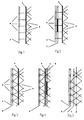
- FIGS. 1-4 there is an information carrier, a liquid crystal display 1, with a grid arranged, individually controllable cells 2 and one Shadow mask 3 with openings 4 assigned to each other.
- the Information carrier 1 and the shadow mask 3 are between one provided on the left in the figures, however not shown light source and also not shown observer, who is on the right of each Figures is arranged.
- the light source shines adequately coherent light.
- the number of openings 4 of the Hole mask 3 corresponds to the number of controllable cells 2 of the Information carrier 1.
- the extent of the openings 4 is less than / equal to 2 ⁇ m, and therefore significantly less than that of Cells 2 (approx. 50 ⁇ m).
- the locations of most openings 4 deviate from their while maintaining the assignment to the cells 2 Middle layers.
- the size and direction of the deviations are randomly distributed so that within the viewing angle practically no periodicity, neither in a row nor in a column.
- FIG. A very simple embodiment is shown in FIG. That from left coherent falling on the liquid crystal display 1 Light is modulated by the transmission of the cells 2. It spreads due to the size of the dimensions of the cells 2 practically unbending straight until it fits onto the shadow mask 3 meets. Due to the small size of the openings 4 of the shadow mask 3 the light is diffracted into large angles. The modulated light creates the 3D image. It can be viewed at large angles will.
- an amplitude mask 5 is additionally provided. This gives you the option of either sharing tasks, - Phase modulation in, information carrier 1 and amplitude modulation in the amplitude mask 5 - or an additional Amplitude modulation, if with the information carrier too amplitude modulation has already taken place.
- the amplitude mask is also a liquid crystal display here.
- the low luminous efficacy in the versions according to the two first figures will be introduced by the additional Lens mask 6 according to FIG. 3 significantly improved.
- the light each cell 2 is focused on the associated opening.
- the Focus is on most points, according to the off-center position of the openings 4 simultaneously with the corresponding changes in direction connected.
- the lens mask 6 From left to right on the right are arranged: the lens mask 6, the shadow mask 3, the information carrier 1, and the amplitude mask 5.
- the Shadow mask In FIG. 5, compared to the embodiment according to FIG. 3, the Shadow mask.
- the previously in the openings 4 of the shadow mask focused light points 4 keep their position. they are as before with irregular distances in the area 8 distributed.
- a deflection mask 7 is interposed the optical axes of the deflected with the lens mask Focusing cone roughly parallel to the surface normal aligns.
Landscapes
- Physics & Mathematics (AREA)
- General Physics & Mathematics (AREA)
- Nonlinear Science (AREA)
- Optics & Photonics (AREA)
- Crystallography & Structural Chemistry (AREA)
- Chemical & Material Sciences (AREA)
- Mathematical Physics (AREA)
- Business, Economics & Management (AREA)
- Accounting & Taxation (AREA)
- Marketing (AREA)
- Engineering & Computer Science (AREA)
- Theoretical Computer Science (AREA)
- Holo Graphy (AREA)
Description
Claims (8)
- Holografisches Display zur Darstellung von dreidimensionalen Bildern mitdadurch gekennzeichnet, daßeiner Lichtquelle,mit einem im Beleuchtungsstrahl der Lichtquelle angeordneten Informationsträger (1), dessen Zellen (2) in ihren Transmissionseigenschaften individuell ansteuerbar sind zur Modulation des Beleuchtungsstrahls mit der Information des darzustellenden holografischen Bildes,und daß die Elemente (4) in unregelmäßigen Abständen zueinander über die Fläche des Informationsträgers verteilt sind, so daß innerhalb des Betrachtungswinkels praktisch keine Periodizität auftritt.jeder der Zellen (2) des Informationsträgers (1) ein Element (4), wie die Öffnungen einer Lochmaske (3) oder wie eine Linsenmaske, die durch eine Ablenkungsmaske (7) auf eine Fläche (8) fokussierte Lichtpunkte erzeugt, zugeordnet ist, das von der zugehörigen Zelle (2) transmittiertes Licht in der Weise einer Punktlichtquelle in große Winkel ausstrahlt, so daß das Bild unter großen Betrachtungswinkeln sichtbar ist,
- Holografisches Display nach Anspruch 1, dadurch gekennzeichnet, daß dem Informationsträger (1) eine Lochmaske (3) mit punktförmigen Öffnungen (4) zugeordnet ist und die Lagen der meisten Öffnungen (4) in der Lochmaske (3) bei Wahrung ihrer optischen Zuordnung zu ihren Zellen (2) von der Mittenlage ihrer zugehörigen Zellen (2) unregelmäßig abweichen.
- Holografisches Display nach Anspruch 1, dadurch gekennzeichnet, daß dem Informationsträger (1) eine Linsenmaske (6) mit zellenweise angeordneten, fokussierenden Elementen, deren Brennpunkte in einer Fläche (8) mit unregelmäßigen Abständen zueinander liegen, zugeordnet sind.
- Holografisches Display nach den Ansprüchen 2 und 3, dadurch gekennzeichnet, daß die Brennpunkte der fokussierenden und ablenkenden Elemente in den punktförmigen Öffnungen (4) der Lochmaske (3) liegen.
- Holografisches Display nach Anspruch 3, dadurch gekennzeichnet, daß zwischen der Linsenmaske (6) und der Fläche (8), in der die Brennpunkte der fokussierenden und ablenkenden Elemente liegen, eine Ablenkungsmaske (7) mit die optischen Achsen der Fokussierungskegel etwa parallel zur Bildnormalen ablenkenden bzw. ausrichtenden Elementen angeordnet ist.
- Holografisches Display nach den Ansprüchen 3 oder/und 5, dadurch gekennzeichnet, daß die fokussierenden oder/und ablenkenden Elemente holografische optische Elemente sind.
- Holografisches Display nach Anspruch 1, dadurch gekennzeichnet, daß der Lochmaske (3) eine Amplitudenmaske (5) mit die Lichtintensität steuernden Öffnungen zugeordnet ist.
- Holografisches Display nach Anspruch 3, dadurch gekennzeichnet, daß die fokussierenden Elemente in einem Mikrolinsen-Array angeordnet sind.
Applications Claiming Priority (3)
| Application Number | Priority Date | Filing Date | Title |
|---|---|---|---|
| DE4225589 | 1992-08-05 | ||
| DE4225589A DE4225589A1 (de) | 1992-08-05 | 1992-08-05 | Holografisches Display |
| PCT/DE1993/000689 WO1994003843A1 (de) | 1992-08-05 | 1993-08-05 | Holografisches display |
Publications (2)
| Publication Number | Publication Date |
|---|---|
| EP0654153A1 EP0654153A1 (de) | 1995-05-24 |
| EP0654153B1 true EP0654153B1 (de) | 1998-04-08 |
Family
ID=6464720
Family Applications (1)
| Application Number | Title | Priority Date | Filing Date |
|---|---|---|---|
| EP93918880A Expired - Lifetime EP0654153B1 (de) | 1992-08-05 | 1993-08-05 | Holografisches display |
Country Status (3)
| Country | Link |
|---|---|
| EP (1) | EP0654153B1 (de) |
| DE (2) | DE4225589A1 (de) |
| WO (1) | WO1994003843A1 (de) |
Families Citing this family (3)
| Publication number | Priority date | Publication date | Assignee | Title |
|---|---|---|---|---|
| US5526022A (en) | 1993-01-06 | 1996-06-11 | Virtual I/O, Inc. | Sourceless orientation sensor |
| GB2446617A (en) * | 2007-02-16 | 2008-08-20 | Indepth Optics Ltd | 3D holographic display |
| AU2021265281A1 (en) * | 2020-04-29 | 2022-12-15 | Marsupial Holdings, Inc. | On-axis holographic sight |
Citations (1)
| Publication number | Priority date | Publication date | Assignee | Title |
|---|---|---|---|---|
| EP0449164A2 (de) * | 1990-03-26 | 1991-10-02 | Matsushita Electric Industrial Co., Ltd. | Verfahren zum Erzeugen synthetischer Hologramme |
Family Cites Families (1)
| Publication number | Priority date | Publication date | Assignee | Title |
|---|---|---|---|---|
| JPH01189685A (ja) * | 1988-01-26 | 1989-07-28 | Seiko Epson Corp | 液晶ライトバルブ及び液晶ライトバルブを備えたビデオプロジェクター |
-
1992
- 1992-08-05 DE DE4225589A patent/DE4225589A1/de not_active Withdrawn
-
1993
- 1993-08-05 EP EP93918880A patent/EP0654153B1/de not_active Expired - Lifetime
- 1993-08-05 DE DE59308396T patent/DE59308396D1/de not_active Expired - Fee Related
- 1993-08-05 WO PCT/DE1993/000689 patent/WO1994003843A1/de not_active Ceased
Patent Citations (1)
| Publication number | Priority date | Publication date | Assignee | Title |
|---|---|---|---|---|
| EP0449164A2 (de) * | 1990-03-26 | 1991-10-02 | Matsushita Electric Industrial Co., Ltd. | Verfahren zum Erzeugen synthetischer Hologramme |
Also Published As
| Publication number | Publication date |
|---|---|
| WO1994003843A1 (de) | 1994-02-17 |
| DE4225589A1 (de) | 1994-02-10 |
| DE59308396D1 (en) | 1998-05-14 |
| EP0654153A1 (de) | 1995-05-24 |
Similar Documents
| Publication | Publication Date | Title |
|---|---|---|
| DE69602297T2 (de) | Flüssigkristallanzeigevorrichtung für dreidimensionale Bildwiedergabe | |
| DE69735989T2 (de) | Richtanzeige | |
| DE69603374T2 (de) | Autostereoskopische anzeige | |
| DE3884376T2 (de) | Farbeanzeigeanordnung und verfahren unter verwendung von holographischen linsen. | |
| EP1880252B1 (de) | Projektionsvorrichtung und verfahren zur holographischen rekonstruktion von szenen | |
| EP1658731B1 (de) | Autostereoskopisches multi-user-display | |
| DE69331925T2 (de) | Stereoskopisches Darstellungsgerät | |
| EP2847999B1 (de) | Bildprojektion mit mehrkanaloptik mit nicht kreisförmiger gesamtapertur | |
| DE60129357T2 (de) | Achromatische flachtafelkamera | |
| DE69820363T2 (de) | Verfahren und gerät zur darstellung dreidimensionaler bilder | |
| DE69619880T2 (de) | Anzeigegerät mit Verzerrungskorrektur | |
| DE69525265T2 (de) | Projektionssystem | |
| DE60005162T2 (de) | Projektionsanzeige mit grossem sichtfeld | |
| EP1658733B1 (de) | Strahlteiler zur Bildtrennung für Autostereoskopie | |
| EP1695562A1 (de) | Autostereoskopische anzeigevorrichtung mit positionsnachführung für mehrere benutzer | |
| WO2006021242A1 (de) | Lentikel-prismen-einheit | |
| WO2008015283A1 (de) | Holographisches rekonstruktionssystem mit vergrössertem sichtbarkeitsbereich | |
| EP1012636A1 (de) | Anordnung zur dreidimensionalen darstellung | |
| EP1766459A1 (de) | Multi-linsen-lentikular und beleuchtungseinrichtung für autostereoskopisches display | |
| DE102008043620A1 (de) | Beleuchtungseinrichtung für ein autostereoskopisches Display | |
| DE4309667A1 (de) | Optisches System zur zwei- und dreidimensionalen Darstellung von Information | |
| DE69422139T2 (de) | Optisches instrument und optisches element dafür | |
| DE112017007244T5 (de) | Darstellungsvorrichtung | |
| WO2009080576A1 (de) | Steuerbarer lichtmodulator | |
| DE10260611A1 (de) | Kollimatorlinse, Kollimatorsystem und Bildanzeigevorrichtung, die ein Kollimatorsystem verwendet |
Legal Events
| Date | Code | Title | Description |
|---|---|---|---|
| PUAI | Public reference made under article 153(3) epc to a published international application that has entered the european phase |
Free format text: ORIGINAL CODE: 0009012 |
|
| 17P | Request for examination filed |
Effective date: 19950227 |
|
| AK | Designated contracting states |
Kind code of ref document: A1 Designated state(s): DE FR GB |
|
| 17Q | First examination report despatched |
Effective date: 19960725 |
|
| GRAG | Despatch of communication of intention to grant |
Free format text: ORIGINAL CODE: EPIDOS AGRA |
|
| GRAG | Despatch of communication of intention to grant |
Free format text: ORIGINAL CODE: EPIDOS AGRA |
|
| GRAG | Despatch of communication of intention to grant |
Free format text: ORIGINAL CODE: EPIDOS AGRA |
|
| GRAG | Despatch of communication of intention to grant |
Free format text: ORIGINAL CODE: EPIDOS AGRA |
|
| GRAH | Despatch of communication of intention to grant a patent |
Free format text: ORIGINAL CODE: EPIDOS IGRA |
|
| GRAH | Despatch of communication of intention to grant a patent |
Free format text: ORIGINAL CODE: EPIDOS IGRA |
|
| GRAA | (expected) grant |
Free format text: ORIGINAL CODE: 0009210 |
|
| AK | Designated contracting states |
Kind code of ref document: B1 Designated state(s): DE FR GB |
|
| PG25 | Lapsed in a contracting state [announced via postgrant information from national office to epo] |
Ref country code: GB Free format text: LAPSE BECAUSE OF FAILURE TO SUBMIT A TRANSLATION OF THE DESCRIPTION OR TO PAY THE FEE WITHIN THE PRESCRIBED TIME-LIMIT Effective date: 19980408 Ref country code: FR Free format text: LAPSE BECAUSE OF FAILURE TO SUBMIT A TRANSLATION OF THE DESCRIPTION OR TO PAY THE FEE WITHIN THE PRESCRIBED TIME-LIMIT Effective date: 19980408 |
|
| REF | Corresponds to: |
Ref document number: 59308396 Country of ref document: DE Date of ref document: 19980514 |
|
| EN | Fr: translation not filed | ||
| GBV | Gb: ep patent (uk) treated as always having been void in accordance with gb section 77(7)/1977 [no translation filed] |
Effective date: 19980408 |
|
| PLBE | No opposition filed within time limit |
Free format text: ORIGINAL CODE: 0009261 |
|
| STAA | Information on the status of an ep patent application or granted ep patent |
Free format text: STATUS: NO OPPOSITION FILED WITHIN TIME LIMIT |
|
| 26N | No opposition filed | ||
| PGFP | Annual fee paid to national office [announced via postgrant information from national office to epo] |
Ref country code: DE Payment date: 20020805 Year of fee payment: 10 |
|
| PG25 | Lapsed in a contracting state [announced via postgrant information from national office to epo] |
Ref country code: DE Free format text: LAPSE BECAUSE OF NON-PAYMENT OF DUE FEES Effective date: 20040302 |