EP0653616A2 - Device for monitoring the resistance to ageing of structures - Google Patents
Device for monitoring the resistance to ageing of structures Download PDFInfo
- Publication number
- EP0653616A2 EP0653616A2 EP94113351A EP94113351A EP0653616A2 EP 0653616 A2 EP0653616 A2 EP 0653616A2 EP 94113351 A EP94113351 A EP 94113351A EP 94113351 A EP94113351 A EP 94113351A EP 0653616 A2 EP0653616 A2 EP 0653616A2
- Authority
- EP
- European Patent Office
- Prior art keywords
- der
- rib
- monitoring
- load
- notches
- Prior art date
- Legal status (The legal status is an assumption and is not a legal conclusion. Google has not performed a legal analysis and makes no representation as to the accuracy of the status listed.)
- Withdrawn
Links
Images


Classifications
-
- G—PHYSICS
- G01—MEASURING; TESTING
- G01M—TESTING STATIC OR DYNAMIC BALANCE OF MACHINES OR STRUCTURES; TESTING OF STRUCTURES OR APPARATUS, NOT OTHERWISE PROVIDED FOR
- G01M5/00—Investigating the elasticity of structures, e.g. deflection of bridges or air-craft wings
- G01M5/0033—Investigating the elasticity of structures, e.g. deflection of bridges or air-craft wings by determining damage, crack or wear
Landscapes
- Engineering & Computer Science (AREA)
- Aviation & Aerospace Engineering (AREA)
- Physics & Mathematics (AREA)
- General Physics & Mathematics (AREA)
- Investigating Strength Of Materials By Application Of Mechanical Stress (AREA)
- Testing Resistance To Weather, Investigating Materials By Mechanical Methods (AREA)
Abstract
Description
Die Erfindung betrifft eine Einrichtung zum Überwachen der Zeitfestigkeit von Strukturen. Solche Eineinrichtungen werden auch als Lastzähler bezeichnet.The invention relates to a device for monitoring the fatigue strength of structures. Such devices are also known as load counters.
Aus dem Stand der Technik sind als Lastzähler für Metallstrukturen bekannt:
- 1. Überwachung der Struktur mit Hilfe von Dehnmeßstreifen (DMS) und entsprechenden Auswerte-Elektroniken.
- Vorteile:
- - Meßtechnisch sehr genaue Erfassung.
- Nachteile:
- - Verbindung (Klebung) zwischen DMS und Struktur altert und führt im Laufe der Zeit zu Ungenauigkeit.
- Umwelteinflüsse auf die Struktur wie z.B. Korrosion werden nicht erfaßt.
- Streuungen der Materialkennwerte werden nicht erfaßt.
- Energie an der Struktur erforderlich für Speicherelektronik.
- Relativ aufwendige Auswertung.
- Relativ teuer.
- 2. Überwachung der Struktur mit Hilfe von Metallfolien, die durch Dehnungen ihr Reflexionsverhalten verändern.
- Vorteile:
- - Keine Energie an der Erfassungsstelle erforderlich.
- Nachteile:
- - Verbindung (Klebung) zwischen DMS und Struktur altert und führt im Laufe der Zeit zu Ungenauigkeit.
- Korrosion der Meßstreifen macht sie unbrauchbar.
- Von der Geschicklichkeit des Auswerters abhängiges Ergebnis.
- Temperaturzyklen werden als Belastungszyklen registriert.
- Streuungen der Materialkennwerte werden nicht erfaßt.
- Umwelteinflüsse auf die Struktur wie z.B. Korrosion werden nicht erfaßt.
- Relativ teuer.
- 3. Vorrichtung die an der Struktur angebracht ist und in die kleine verschieden gekerbte Probestäbe eingespannt werden.
- Vorteile:
- - Keine Energie an der Erfassungsstelle erforderlich
- Nachteile:
- - Streuungen der Materialkennwerte werden nicht erfaßt.
- Umwelteinflüsse auf die Struktur wie z.B. Korrosion werden nicht erfaßt.
- Relativ aufwendig, empfindlich und teuer.
- 1. Monitoring the structure with the help of strain gauges (DMS) and corresponding evaluation electronics.
- Benefits:
- - Very precise measurement.
- Disadvantage:
- - The connection (glue) between the strain gauge and the structure ages and leads to inaccuracy over time.
- Environmental influences on the structure, such as corrosion, are not recorded.
- Variations in the material parameters are not recorded.
- Energy on the structure required for storage electronics.
- Relatively complex evaluation.
- Relative expensive.
- 2. Monitoring the structure with the help of metal foils caused by stretching change their reflection behavior.
- Benefits:
- - No energy required at the detection point.
- Disadvantage:
- - The connection (glue) between the strain gauge and the structure ages and leads to inaccuracy over time.
- Corrosion of the measuring strips makes them unusable.
- Result dependent on the skill of the evaluator.
- Temperature cycles are registered as load cycles.
- Variations in the material parameters are not recorded.
- Environmental influences on the structure, such as corrosion, are not recorded.
- Relative expensive.
- 3. Device which is attached to the structure and in which small different notched test bars are clamped.
- Benefits:
- - No energy required at the detection point
- Disadvantage:
- - Variations in the material parameters are not recorded.
- Environmental influences on the structure, such as corrosion, are not recorded.
- Relatively complex, sensitive and expensive.
Aufgabe der Erfindung ist es, einen Lastzähler zu schaffen, der sämtliche Einflüsse auf die Struktur einschliesslich Korrosion und anderer Umwelteinflüsse erfaßt und durch Sichtkontrolle ablesbar ist.The object of the invention is to provide a load counter which detects all influences on the structure including corrosion and other environmental influences and can be read off by visual inspection.
Diese Aufgabe wird erfindungsgemäß durch den Gegenstand des Hauptanspruchs gelöst. Die Unteransprüche betreffen vorteilhafte Ausgestaltungen der Erfindung.This object is achieved by the subject matter of the main claim. The subclaims relate to advantageous refinements of the invention.
Beim Gegenstand der Erfindung wird eine mit verschiedenen Kerben geschädigte Probe in die zu überwachende Struktur integriert.In the subject matter of the invention, a sample damaged with different notches is integrated into the structure to be monitored.
Die Probe und die Kerben werden dabei so gestaltet, daß die Probe an den verschiedenen Kerben, z.B. bei 50, 80 und 100 % der Lebensdauer durchreißt. Durch die Gestaltung der Probe wird erreicht, daß sich der Riß einer Kerbe nicht in die Struktur fortsetzt. Vorzugweise sollte die Probe in die Struktur integriert sein, um damit alle Streuungen des Materials abzudecken. Ist eine Integration der Probe in die Struktur nicht möglich, ist auch eine Verbindung der Probe mit der Struktur durch geeignete Verbindungselemente (z.B. Schrauben, Niete, Stifte) möglich.The sample and the notches are designed so that the sample on the different notches, e.g. tears at 50, 80 and 100% of the lifespan. The design of the sample ensures that the crack of a notch does not continue in the structure. The sample should preferably be integrated into the structure in order to cover all scattering of the material. If the sample cannot be integrated into the structure, the sample can also be connected to the structure using suitable connecting elements (e.g. screws, rivets, pins).
Vorteile der Erfindung:
- Keine Energie an der Erfassungsstelle erforderlich.
- Streuungen der Materialkennwerte werden erfaßt.
- Umwelteinflüsse auf die Struktur wie z.B. Korrosion werden erfaßt.
- Relativ kostengünstig und kann deshalb auch an einem Strukturmodul öfters vorgesehen werden.
Dadurch ist Redundanz möglich und die Erfassung der Streuung der Belastung durch die Modularität von Brücken kann erfaßt werden. - Auswertung erfolgt im Rahmen der normalen Inspektion.
- Kein Auswertegerät erforderlich.
- No energy required at the detection point.
- Variations in the material parameters are recorded.
- Environmental influences on the structure such as corrosion are recorded.
- Relatively inexpensive and can therefore often be provided on a structural module.
This enables redundancy and the detection of the spread of the load due to the modularity of bridges can be recorded. - Evaluation takes place as part of the normal inspection.
- No evaluation device required.
Die Erfindung wird nachfolgend anhand von Figuren näher erläutert.The invention is explained in more detail below with reference to figures.
Es zeigen:
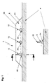
- Fig. 1 einen in eine Struktur integrierten erfindungsgemäßen Lastzähler,
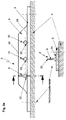
- Fig. 2a einen auf die Struktur aufgeschraubten Lastzähler, winkelförmig,
- Fig. 2b einen auf die Struktur aufgeschraubten Lastzähler, flach symmetrisch,
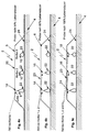
- Fig. 3 beispielhafte Abmessungen für den Lastzähler von Fig. 1,
- Fig. 4a bis 4c drei verschiedene Stufen der Schädigung des Lastzählers von Fig. 1.
- 1 shows a load counter according to the invention integrated into a structure,
- 2a a load counter screwed onto the structure, angular,
- 2b a load counter screwed onto the structure, flat symmetrical,
- 3 exemplary dimensions for the load counter of FIG. 1,
- 4a to 4c three different levels of damage to the load counter of Fig. 1st
Fig. 1 zeigt einen Lastzähler 2 (auch als Probe bezeichnet), der in eine Struktur 4 integriert ist.1 shows a load counter 2 (also referred to as a sample) which is integrated in a
Fig. 2a, b zeigen einen Lastzähler 2, der in eine Platte 3 integriert ist, die mit der Struktur 4, z.B. mittels Schrauben, fest verbunden ist.2a, b show a
Der Lastzähler besteht in Fig. 1 und 2 aus einer Rippe 6. In diese Rippe 6 sind nach dem Ergebnis einer bruchmechanischen Auslegung (Größe, Gestalt, Abstand) mehrere Kerben 8, 10, 12 eingearbeitet, die so gestaltet sind, daß nach einer definierten Schädigung der Struktur 4 Risse 14, 16, 18 (Fig. 4a bis 4c) von der Kerbe 8, 10, 12 zur Außenseite 20 der Rippe 6 auftreten. Auf der entgegengesetzten Seite am Fuß der Kerbe ist die Probe 2 so gestaltet, daß während des gesamten Lebens der Struktur 4 keine Anrisse auftreten können. Dies wird vor allem dadurch erreicht, daß
- die
Kerbe - daß der Grund der Kerbe unmittelbar
am Fuß 24 der Rippe liegt.
- the
notch large curve 22 at its base and - that the bottom of the notch lies directly at the
foot 24 of the rib.
Dadurch wird erreicht, daß der Querschnitt am Kerbgrund stark Zunimmt und somit die Spannungserhöhung durch die Anbindung der Probe klein und unkritisch bleibt. Dies ist besonders dann erforderlich, wenn die Probe 2 bei den stark gekerbten Löchern (Fig. 4b) bereits durchgerissen ist.The result is that the cross-section at the notch base increases significantly and the stress increase due to the connection of the sample remains small and uncritical. This is particularly necessary when
Die in Fig. 3 gezeigten beispielhaften Abmessungen des Lastzählers 2, sind: Länge der Rippe 6, ca. 20 mal Höhe der Rippe, Höhe der Rippe 10 bis 20 mm, Wandstärke der Rippe 1 bis 4 mm. Der Durchmesser der ausgerundeten Kerben beträgt beispielsweise 6 bis 8 mm. Die Rippe 6 besteht vorzugsweise aus dem gleichen Material wie die Struktur 4. Dies kann z.B. eine Aluminiumlegierung oder auch Stahl sein. Grundsätzlich kann der erfindungsgemäße Lastzähler bei allen duktilen, kerbempfindlichen Werkstoffen angewendet werden.The exemplary dimensions of the
Fig. 4a, 4b und 4c zeigen den Lastzähler 2 nach 50 %, 80 % und 100 % seiner Lebensdauer, wobei die von den Kerben 8, 10, 12 ausgehenden Risse 14, 16, 18 bei einer Sichtkontrolle ohne technische Hilfsmittel zu erkennen sind.4a, 4b and 4c show the
Der erfindungsgemäße Lastzähler kann universell bei allen Arten von Strukturen wie Strassenbrücken, Krane, Flugzeuge, Schiffe, Bahnen, Maschinen eingesetzt werden.
In Versuchen wurde der Lastzähler erfolgreich an modularen Pionierbrücken eingesetzt. Solche Pionierbrücken werden auf Zeitfestigkeit ausgelegt (z.B. 10.000 Überfahrten eines Kampfpanzers). Die Belastung der einzelnen Module ist jedoch im praktischen Einsatz der Brücke recht unterschiedlich.The load counter according to the invention can be used universally in all types of structures such as road bridges, cranes, airplanes, ships, trains, machines.
In trials, the load counter was successfully used on modular pioneer bridges. Such pioneer bridges are designed for durability (e.g. 10,000 crossings of a main battle tank). However, the load on the individual modules varies considerably in practical use of the bridge.
Die Parameter sind:
- Einbauort in der Brücke
- Spannweite der Brücke
- Gewicht der überfahrenden Fahrzeuge.
- Installation location in the bridge
- Span of the bridge
- Weight of vehicles driving over.
Claims (4)
Applications Claiming Priority (2)
| Application Number | Priority Date | Filing Date | Title |
|---|---|---|---|
| DE4338850 | 1993-11-13 | ||
| DE4338850A DE4338850A1 (en) | 1993-11-13 | 1993-11-13 | Device for monitoring the durability of structures |
Publications (2)
| Publication Number | Publication Date |
|---|---|
| EP0653616A2 true EP0653616A2 (en) | 1995-05-17 |
| EP0653616A3 EP0653616A3 (en) | 1995-11-08 |
Family
ID=6502560
Family Applications (1)
| Application Number | Title | Priority Date | Filing Date |
|---|---|---|---|
| EP94113351A Withdrawn EP0653616A3 (en) | 1993-11-13 | 1994-08-26 | Device for monitoring the resistance to ageing of structures. |
Country Status (3)
| Country | Link |
|---|---|
| US (2) | US5520055A (en) |
| EP (1) | EP0653616A3 (en) |
| DE (1) | DE4338850A1 (en) |
Cited By (4)
| Publication number | Priority date | Publication date | Assignee | Title |
|---|---|---|---|---|
| EP2634446A1 (en) * | 2012-02-28 | 2013-09-04 | Meritor Heavy Vehicle Braking Systems (UK) Limited | A cast or forged component with fatigue life indication |
| WO2016110680A1 (en) * | 2015-01-05 | 2016-07-14 | Bae Systems Plc | Mobile bridge apparatus |
| CN107905085A (en) * | 2017-11-30 | 2018-04-13 | 东台苏明高速钢制品有限公司 | A kind of pontoon bridge steel construction |
| US10202729B2 (en) | 2015-01-05 | 2019-02-12 | Bae Systems Plc | Mobile bridge module |
Families Citing this family (22)
| Publication number | Priority date | Publication date | Assignee | Title |
|---|---|---|---|---|
| US5763788A (en) * | 1996-01-25 | 1998-06-09 | Man Technologie Ag | Portable device for counting and sorting load cycles in supporting structures with various loads |
| JP2799431B2 (en) * | 1996-05-15 | 1998-09-17 | 広島大学長 | Sacrificial specimen for fatigue damage prediction monitoring of structures |
| US6029526A (en) * | 1998-05-14 | 2000-02-29 | Shannon & Wilson, Inc. | Method and apparatus for measuring in situ or stress of concrete |
| JP2952594B1 (en) * | 1998-09-28 | 1999-09-27 | 株式会社ビーエムシー | Sensor for detecting fatigue damage of structural material and method of mounting the same |
| DE19918219C1 (en) * | 1999-04-22 | 2001-01-18 | Dornier Gmbh | Service life indicator for highly stressed lightweight structures |
| US20040087978A1 (en) * | 2002-08-27 | 2004-05-06 | Velez Juan Manuel | Surgical fascia closure instrument, guide and method |
| US6983660B2 (en) | 2003-04-29 | 2006-01-10 | Young Wuk Kwon | Fatigue measurement device and method |
| US7377179B2 (en) * | 2005-11-14 | 2008-05-27 | General Electric Company | System, method, and apparatus for wireless non-powered stress history and fatigue monitoring of a structure |
| US7987728B2 (en) * | 2006-07-07 | 2011-08-02 | The University Of Houston System | Piezoceramic-based smart aggregate for unified performance monitoring of concrete structures |
| GB0719272D0 (en) * | 2007-10-04 | 2007-11-21 | Airbus Uk Ltd | Apparatus with damage indication feature |
| US8202378B2 (en) * | 2009-01-14 | 2012-06-19 | The University Of Kansas | Apparatus and method for enhancement of connection performance and fatigue detection |
| US8200442B2 (en) * | 2009-03-16 | 2012-06-12 | Sikorsky Aircraft Corporation | Usage monitor reliability factor using an advanced fatigue reliability assessment model |
| DE102009056584B4 (en) | 2009-12-01 | 2014-09-25 | Gottfried Wilhelm Leibniz Universität Hannover | Component, method for introducing information into a component and method for determining a load history of a component |
| FR2972799B1 (en) * | 2011-03-17 | 2016-07-22 | Airbus Operations Sas | DEVICE FOR DETECTING SHOCKS ON A STRUCTURE |
| JP2013002960A (en) * | 2011-06-16 | 2013-01-07 | Universal Shipbuilding Corp | Fatigue monitoring structure and steel structure |
| GB201216787D0 (en) * | 2012-09-20 | 2012-11-07 | Rolls Royce Plc | Method and system for predicting the serviceable life of a component |
| GB201402597D0 (en) | 2014-02-14 | 2014-04-02 | Rolls Royce Plc | Method and system for predicting the serviceable life of a component |
| US9989579B2 (en) | 2016-06-20 | 2018-06-05 | Eaton Intelligent Power Limited | Monitoring systems and methods for detecting thermal-mechanical strain fatigue in an electrical fuse |
| US10648871B2 (en) | 2017-10-05 | 2020-05-12 | International Business Machines Corporation | Fracture ring sensor |
| US11143718B2 (en) | 2018-05-31 | 2021-10-12 | Eaton Intelligent Power Limited | Monitoring systems and methods for estimating thermal-mechanical fatigue in an electrical fuse |
| US11289298B2 (en) | 2018-05-31 | 2022-03-29 | Eaton Intelligent Power Limited | Monitoring systems and methods for estimating thermal-mechanical fatigue in an electrical fuse |
| JP6788291B1 (en) * | 2019-06-03 | 2020-11-25 | 株式会社イクシス | Inspection support system |
Citations (3)
| Publication number | Priority date | Publication date | Assignee | Title |
|---|---|---|---|---|
| JPS60209137A (en) * | 1984-04-03 | 1985-10-21 | Topy Ind Ltd | Predicting method of fatigue damage |
| US4590804A (en) * | 1984-01-23 | 1986-05-27 | Tensiodyne Scientific Corporation | Device for monitoring fatigue life |
| US5237875A (en) * | 1991-03-29 | 1993-08-24 | Tensiodyne Corporation | Metal fatigue detector |
Family Cites Families (7)
| Publication number | Priority date | Publication date | Assignee | Title |
|---|---|---|---|---|
| US2724964A (en) * | 1952-09-02 | 1955-11-29 | Magnaflux Corp | Method of determining strain values in rigid articles |
| US3572091A (en) * | 1968-09-27 | 1971-03-23 | Keith H Mcfarland | Mechanical strain indicator |
| GB1293878A (en) * | 1970-07-31 | 1972-10-25 | Hawker Siddeley Aviation Ltd | Improvements in or relating to fatigue sensors |
| US3786679A (en) * | 1972-04-12 | 1974-01-22 | Battelle Memorial Institute | Fatigue indication |
| US5161891A (en) * | 1991-02-12 | 1992-11-10 | Practical Transportation, Inc. | Process for determining and controlling railroad rail's neutral temperature to prevent track buckling and rail fractures |
| US5319982A (en) * | 1992-07-01 | 1994-06-14 | Tensiodyne Scientific, Inc. | Device for monitoring the fatigue life of a structural member and a method of making same |
| US5325721A (en) * | 1993-02-17 | 1994-07-05 | Minnesota Mining And Manufacturing Company | System for indicating exposure to preselected temperatures or tampering |
-
1993
- 1993-11-13 DE DE4338850A patent/DE4338850A1/en not_active Withdrawn
-
1994
- 1994-08-26 EP EP94113351A patent/EP0653616A3/en not_active Withdrawn
- 1994-10-31 US US08/331,743 patent/US5520055A/en not_active Expired - Fee Related
-
1995
- 1995-11-15 US US08/558,169 patent/US5614680A/en not_active Expired - Fee Related
Patent Citations (3)
| Publication number | Priority date | Publication date | Assignee | Title |
|---|---|---|---|---|
| US4590804A (en) * | 1984-01-23 | 1986-05-27 | Tensiodyne Scientific Corporation | Device for monitoring fatigue life |
| JPS60209137A (en) * | 1984-04-03 | 1985-10-21 | Topy Ind Ltd | Predicting method of fatigue damage |
| US5237875A (en) * | 1991-03-29 | 1993-08-24 | Tensiodyne Corporation | Metal fatigue detector |
Non-Patent Citations (1)
| Title |
|---|
| PATENT ABSTRACTS OF JAPAN vol. 010 no. 068 (P-437) ,18.März 1986 & JP-A-60 209137 (TOPY KOGYO KK) 21.Oktober 1985, * |
Cited By (7)
| Publication number | Priority date | Publication date | Assignee | Title |
|---|---|---|---|---|
| EP2634446A1 (en) * | 2012-02-28 | 2013-09-04 | Meritor Heavy Vehicle Braking Systems (UK) Limited | A cast or forged component with fatigue life indication |
| WO2016110680A1 (en) * | 2015-01-05 | 2016-07-14 | Bae Systems Plc | Mobile bridge apparatus |
| US10190936B2 (en) | 2015-01-05 | 2019-01-29 | Bae Systems Plc | Mobile bridge apparatus |
| US10202729B2 (en) | 2015-01-05 | 2019-02-12 | Bae Systems Plc | Mobile bridge module |
| EP3242972B1 (en) | 2015-01-05 | 2020-07-15 | BAE Systems PLC | Mobile bridge apparatus |
| AU2016205921B2 (en) * | 2015-01-05 | 2020-09-10 | Bae Systems Plc | Mobile bridge apparatus |
| CN107905085A (en) * | 2017-11-30 | 2018-04-13 | 东台苏明高速钢制品有限公司 | A kind of pontoon bridge steel construction |
Also Published As
| Publication number | Publication date |
|---|---|
| US5614680A (en) | 1997-03-25 |
| US5520055A (en) | 1996-05-28 |
| EP0653616A3 (en) | 1995-11-08 |
| DE4338850A1 (en) | 1995-05-18 |
Similar Documents
| Publication | Publication Date | Title |
|---|---|---|
| EP0653616A2 (en) | Device for monitoring the resistance to ageing of structures | |
| DE3631647C2 (en) | Arrangement for absorbing bends and deformations in a mechanical part or structure | |
| DE102005030971B4 (en) | Ball joint with sensor device, method for load measurement and method for wear measurement | |
| EP1904356B1 (en) | Method and device for determining the risk of derailment of railway vehicles | |
| DE102009002188A1 (en) | Force transducer for measuring support forces in a support element | |
| DE4303049C2 (en) | Strain gauge and method for its attachment to a cylindrical component | |
| WO1991016636A1 (en) | Device for measuring acceleration via piezoelectric transducers | |
| DE102010007937A1 (en) | Method and device for the automatic calibration of strainers or force transducers | |
| EP3220116B1 (en) | Force sensor device | |
| EP1046894B1 (en) | Lifetime indicator for highly stressed lightweight structures | |
| DE2027119B2 (en) | Ball joint connection between a load-bearing platform and pressure measuring cells of an electric balance | |
| DE3740189C2 (en) | ||
| DE10300947A1 (en) | Mast, antenna and anchored upright structure testing method, wherein the mast is set in vibration and the resultant reactive forces measured using acceleration sensors | |
| DE19504050C2 (en) | Device for recording load cycles of supporting structures | |
| DE102010008397B4 (en) | Sensor system for the determination of fatigue on metallic components | |
| DE4408043C2 (en) | Device for monitoring the clamping force of a clamping element | |
| DE19514050A1 (en) | Method and device for detecting loads on lifting and pulling devices | |
| WO2011110158A2 (en) | Measuring device for detecting shape changes | |
| DE3111698A1 (en) | "METHOD AND DEVICE FOR CHECKING COMPONENTS IN THE AREA OF OVERLAPPING CONNECTIONS" | |
| DE102017125228B4 (en) | STRAIN MEASURING DEVICE | |
| DE102017102040B4 (en) | Device for detecting changes in the spatial distance between two stationary anchored measuring points | |
| KR100545342B1 (en) | a fixing jig for a cylindrical concrete specimens reinforced with fiber sheet | |
| DE102007052201B3 (en) | Wear monitoring and measuring arrangement for e.g. steel bridge construction, has receiver arranged at holder in plane between magnets, where surface of sensor is spaced against measuring point at carrier part and adjustable against point | |
| DE102017114651A1 (en) | Method and device for assessing the connection quality of anchor devices | |
| DE102013005569A1 (en) | Arrangement for load measurement or load adjustment |
Legal Events
| Date | Code | Title | Description |
|---|---|---|---|
| PUAI | Public reference made under article 153(3) epc to a published international application that has entered the european phase |
Free format text: ORIGINAL CODE: 0009012 |
|
| AK | Designated contracting states |
Kind code of ref document: A2 Designated state(s): DE FR GB IT SE |
|
| PUAL | Search report despatched |
Free format text: ORIGINAL CODE: 0009013 |
|
| AK | Designated contracting states |
Kind code of ref document: A3 Designated state(s): DE FR GB IT SE |
|
| 17P | Request for examination filed |
Effective date: 19960430 |
|
| 17Q | First examination report despatched |
Effective date: 19970528 |
|
| STAA | Information on the status of an ep patent application or granted ep patent |
Free format text: STATUS: THE APPLICATION IS DEEMED TO BE WITHDRAWN |
|
| 18D | Application deemed to be withdrawn |
Effective date: 19971008 |