EP0653528A1 - Under-roof construction - Google Patents
Under-roof construction Download PDFInfo
- Publication number
- EP0653528A1 EP0653528A1 EP94117248A EP94117248A EP0653528A1 EP 0653528 A1 EP0653528 A1 EP 0653528A1 EP 94117248 A EP94117248 A EP 94117248A EP 94117248 A EP94117248 A EP 94117248A EP 0653528 A1 EP0653528 A1 EP 0653528A1
- Authority
- EP
- European Patent Office
- Prior art keywords
- slatted
- roof construction
- slatted head
- construction according
- head
- Prior art date
- Legal status (The legal status is an assumption and is not a legal conclusion. Google has not performed a legal analysis and makes no representation as to the accuracy of the status listed.)
- Granted
Links
Images
Classifications
-
- E—FIXED CONSTRUCTIONS
- E04—BUILDING
- E04B—GENERAL BUILDING CONSTRUCTIONS; WALLS, e.g. PARTITIONS; ROOFS; FLOORS; CEILINGS; INSULATION OR OTHER PROTECTION OF BUILDINGS
- E04B7/00—Roofs; Roof construction with regard to insulation
- E04B7/20—Roofs consisting of self-supporting slabs, e.g. able to be loaded
- E04B7/22—Roofs consisting of self-supporting slabs, e.g. able to be loaded the slabs having insulating properties, e.g. laminated with layers of insulating material
- E04B7/225—Roofs consisting of self-supporting slabs, e.g. able to be loaded the slabs having insulating properties, e.g. laminated with layers of insulating material the slabs having non-structural supports for roofing materials
-
- E—FIXED CONSTRUCTIONS
- E04—BUILDING
- E04D—ROOF COVERINGS; SKY-LIGHTS; GUTTERS; ROOF-WORKING TOOLS
- E04D12/00—Non-structural supports for roofing materials, e.g. battens, boards
- E04D12/004—Battens
-
- E—FIXED CONSTRUCTIONS
- E04—BUILDING
- E04D—ROOF COVERINGS; SKY-LIGHTS; GUTTERS; ROOF-WORKING TOOLS
- E04D13/00—Special arrangements or devices in connection with roof coverings; Protection against birds; Roof drainage; Sky-lights
- E04D13/17—Ventilation of roof coverings not otherwise provided for
Definitions
- the invention relates to a sub-roof construction according to the preamble of claim 1.
- This known sub-roof construction consists of a bracket that is attached to the rafters or similar parts and a specially designed slat head rail that is hung directly into the angle.
- the edges in the area of the joint of the rigid foam panels are profiled at an angle to match the shape of the bracket.
- a special cutting of the edges of the rigid foam panels in the area of the joints is required.
- each rigid foam panel is only as wide as a roof covering panel is long, since the brackets must be provided in accordance with the length of a roof covering panel.
- the invention has for its object to provide a sub-roof construction of the type mentioned, which allows easier and faster assembly using standardized rigid foam panels, with the help of a row of brackets on the rafters, several roofing panels can be attached to each other.
- the bracket and slat head rail in addition to the bracket and slat head rail, another part, namely the slat head support, is used to fasten the slat head rail to the bracket.
- the slatted head support is thus arranged between the slatted head rail and the bracket.
- the brackets with the sections of the slatted head girders suspended in them are adapted to the conventional step profiling or folding of the rigid foam panels in the area of the joints, so that the rigid foam panels can be installed as standardized by the manufacturer become.
- the assembly is simplified because fewer brackets have to be fastened and since a large number of slatted head rails can be fastened with the aid of a slatted head support. There are fewer heat or cold bridges and fewer joints. Overall, assembly is simplified and therefore more economical.
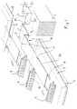
- the sub-roof construction shown in the drawing is used for attachment to rafters 1, or if such are missing, to corresponding plates or elements.
- brackets 2 are fastened in a row parallel to the eaves or to the ridge, which have a section 2a fastened on the rafters 1 and a section 2b projecting vertically upwards with openings or slots 12.
- a slatted head support 3 is attached to each bracket, which consists of a horizontally extending leg 3a and two legs 3c and 3b, each angled at right angles. Hook tabs 7 are formed on the horizontally extending leg 3a.
- These hook tabs 7 are used to fasten the slat head rails 4, which are approximately horseshoe-shaped in cross section, as becomes clear when viewing the drawing. These slatted head rails 4 are hooked into the hook tabs 7 with the aid of their ventilation slots 10 in such a way that the ventilation openings 10 pointing in the ridge direction or lying at the top are hooked in, so that moments are correspondingly well absorbed. The slatted head rails then take up the roof covering panels.
- slatted head rails 4 on a slatted head support 3 with one another are attached so that a corresponding number of roofing panels can be attached to each other with the help of a slatted head support and thus also with the help of a bracket.
- tabs 9 are provided there, which are hooked into the openings 12.
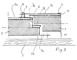
- the profiling of the rigid foam panels 5 is conventionally step-shaped, as can be seen when viewing FIG. 3 and the joint designated 6 there.
- the rigid foam panels are laminated with film 11 or the like and cover all the joints formed in the rigid foam panels.
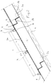
- one or more webs 8 are provided, which in the assembled state also lie in the ventilation slots 10 of the slatted head rail arranged there, as becomes clear when viewing FIG. 2.
- the bracket 2 is attached with its part 2a on the rafter 1.
- the slat head carrier 3 is hung with its tabs 9 into the openings 12 in the part 2b of the bracket 2.
- the web 3a of the Lattenkopfträ gers 3 comes to rest on the underlying hard foam panel, ie on the lamination 11.
- the next hard foam plate, which lies upward and is held by the holding bracket 2, can now be placed.
- the slat head rails 4 are now suspended in the hook tabs 7.
- batten head supports i.e. their legs 3a
- the batten head supports are very long and extend over the entire width of a rigid foam panel, several holding rails and thus several roofing panels can be attached one above the other.
- a special cut of the rigid foam panels is not necessary due to the use of standardized panels with step profiles.
- several slatted head rails and thus a correspondingly large number of roof covering panels can be attached. Since the legs 3a of the slatted head girders overlap one another, they hold the overlapping or overlapping lamination 11 or film on the joints in the joint area and prevent water from penetrating into the joint area.
- a tongue can also be provided, which is then inserted into only one slot of the holder 2 and then folded over.
Abstract
Description
Die Erfindung betrifft eine Unterdachkonstruktion nach dem Oberbegriff des Patentanspruches 1.The invention relates to a sub-roof construction according to the preamble of claim 1.
Eine derartige Unterdachkonstruktion ist aus der DE-PS 32 44 573 (entsprechend EP-PS 0 116 138) bekannt.Such a sub-roof construction is known from DE-PS 32 44 573 (corresponding to EP-PS 0 116 138).
Diese bekannte Unterdachkonstruktion besteht aus einem Haltewinkel, der auf den Sparren oder ähnlichen Teilen befestigt wird und aus einer besonders gestalteten Lattenkopfschiene, die unmittelbar in den Winkel eingehängt wird. Die Kanten im Bereich der Fuge der Hartschaumplatten sind besonders winklig in Anpassung an die Form des Haltewinkels profiliert. Bei der bekannten Unterdachkonstruktion ist ein spezieller Zuschnitt der Kanten der Hartschaumplatten im Bereich der Fugen erforderlich. Auch ist jede Hartschaumplatte nur so breit, wie eine Dacheindeckungsplatte lang ist, da die Haltewinkel jeweils entsprechend der Länge einer Dacheindeckungsplatte vorgesehen sein müssen. Hierdurch ist also ein entsprechender Zuschnitt der Hartschaumplatten erforderlich, und es entstehen eine Vielzahl von Wärme- oder Kältebrücken, da eine entsprechend grosse Anzahl von Haltewinkeln vorgesehen sein muss (entsprechend der Anzahl der Sparren und Fugen der verwendeten Dacheindeckungsplatten). Die Montage ist, bedingt durch die grosse Anzahl der Haltewinkel und den speziellen Zuschnitt, entsprechend zeitaufwendig. Auch sind die Fugenanteile entsprechend gross.This known sub-roof construction consists of a bracket that is attached to the rafters or similar parts and a specially designed slat head rail that is hung directly into the angle. The edges in the area of the joint of the rigid foam panels are profiled at an angle to match the shape of the bracket. In the known sub-roof construction, a special cutting of the edges of the rigid foam panels in the area of the joints is required. In addition, each rigid foam panel is only as wide as a roof covering panel is long, since the brackets must be provided in accordance with the length of a roof covering panel. Hereby a corresponding cut of the rigid foam panels is required, and a large number of heat or cold bridges are created, since a correspondingly large number of mounting brackets must be provided (corresponding to the number of rafters and joints of the roofing panels used). Due to the large number of brackets and the special cut, assembly is correspondingly time-consuming. The joint proportions are also correspondingly large.
Der Erfindung liegt nun die Aufgabe zugrunde, eine Unterdachkonstruktion der eingangs genannten Art zu schaffen, die eine einfachere und schnellere Montage unter Verwendung standardisierter Hartschaumplatten erlaubt, wobei mit Hilfe einer Haltewinkelreihe auf den Sparren auch mehrere untereinanderliegende Dacheindeckungsplatten befestigt werden können.The invention has for its object to provide a sub-roof construction of the type mentioned, which allows easier and faster assembly using standardized rigid foam panels, with the help of a row of brackets on the rafters, several roofing panels can be attached to each other.
Diese Aufgabe wird grundsätzlich durch das Kennzeichen des Patentanspruches 1 gelöst.This object is basically achieved by the characterizing part of patent claim 1.
Erfindungsgemäss wird zusätzlich zu Haltewinkel und Lattenkopfschiene ein weiteres Teil, nämlich der Lattenkopfträger eingesetzt, um die Lattenkopfschiene an dem Haltewinkel zu befestigen. Der Lattenkopfträger ist also zwischen der Lattenkopfschiene und dem Haltewinkel angeordnet. Hierdurch ist es möglich, an einem Lattenkopfträger untereinander, d.h. in Richtung senkrecht zur Traufe, mehrere Dacheindeckungsplatten mit Hilfe eines Haltewinkels zu befestigen, da die Lattenkopfträger in Richtung senkrecht zur Traufe, d.h. in Dachgefällerichtung, entsprechend lang ausgebildet sind und mehrere Lattenkopfschienen aufnehmen können. Die Haltewinkel mit den in sie eingehängten Abschnitten der Lattenkopfträger sind der herkömmlichen Stufenprofilierung oder Falzung der Hartschaumplatten im Bereich der Fugen angepasst, so dass die Hartschaumplatten so eingebaut werden können, wie sie standardisiert vom Hersteller geliefert werden. Die Montage wird vereinfacht, da weniger Haltewinkel befestigt werden müssen und da in einfacher Weise eine grosse Anzahl von Lattenkopfschienen mit Hilfe eines Lattenkopfträgers befestigt werden können. Es entstehen weniger Wärme- oder Kältebrücken sowie Fugenanteile. Insgesamt wird die Montage vereinfacht und damit wirtschaftlicher.According to the invention, in addition to the bracket and slat head rail, another part, namely the slat head support, is used to fasten the slat head rail to the bracket. The slatted head support is thus arranged between the slatted head rail and the bracket. This makes it possible to attach several roofing slabs to one another with a slatted head support, i.e. in the direction perpendicular to the eaves, using a bracket, since the slatted head supports are designed to be long in the direction perpendicular to the eaves, ie in the direction of the roof slope, and can accommodate several slatted head rails. The brackets with the sections of the slatted head girders suspended in them are adapted to the conventional step profiling or folding of the rigid foam panels in the area of the joints, so that the rigid foam panels can be installed as standardized by the manufacturer become. The assembly is simplified because fewer brackets have to be fastened and since a large number of slatted head rails can be fastened with the aid of a slatted head support. There are fewer heat or cold bridges and fewer joints. Overall, assembly is simplified and therefore more economical.
In den Unteransprüchen sind vorteilhafte Ausgestaltungen unter Schutz gestellt. Insbesondere durch Anpassung des Haltewinkels und des Abschnittes des Lattenkopfträgers, der in die Fuge ragt und an dem Haltewinkel befestigt ist, an die entsprechende Profilierung der Hartschaumplatten im Fugenbereich, ist gewährleistet, daß herkömmliche Hartschaumplatten ohne Nachbearbeitung, d.h. ohne weiteren Zuschnitt, eingesetzt werden können, beispielsweise Hartschaumplatten mit Stufenprofilierung. Da sich die Lattenkopfträger in vorteilhafter Weise über die gesamte Breite der Hartschaumplatten erstrecken, können auf den Lattenkopfschienen untereinander eine entsprechenden Anzahl von Dacheindeckungsplatten befestigt werden.Advantageous refinements are protected in the subclaims. In particular, by adapting the mounting bracket and the section of the slatted head support that protrudes into the joint and is attached to the mounting bracket to the corresponding profile of the rigid foam panels in the joint area, it is ensured that conventional rigid foam panels without reworking, i.e. can be used without further cutting, for example rigid foam panels with step profiling. Since the slatted head supports advantageously extend over the entire width of the rigid foam panels, a corresponding number of roofing panels can be attached to one another on the slatted head rails.
An den Haltewinkeln und den Lattenkopfträgern sind besondere Befestigungsmittel, wie Öffnungen, Laschen und Haken ausgebildet, um die einzelnen Verbindungen herzustellen.Special fasteners such as openings, tabs and hooks are formed on the brackets and the batten head supports in order to produce the individual connections.
Im folgenden wird die Erfindung unter Hinweis auf die Zeichnung anhand eines Ausführungsbeispieles näher erläutert.The invention is explained in more detail below with reference to the drawing using an exemplary embodiment.
Es zeigt:
- Fig. 1
- eine explosionsartig auseinandergezogene Darstellung einer Ausführungsform einer Dachunterkonstruktion nach der Erfindung;
- Fig. 2
- einen Schnitt durch die Unterdachkonstruktion nach Fig. 1 im zusammengebauten Zustand; und
- Fig. 3
- eine Einzelheit des Schnittes der Fig. 1 zur Darstellung der Reihenfolge beim Zusammenbau.
- Fig. 1
- an exploded exploded view of an embodiment of a roof substructure according to the invention;
- Fig. 2
- a section through the sub-roof structure of Figure 1 in the assembled state. and
- Fig. 3
- a detail of the section of Fig. 1 to illustrate the order in assembly.
Die in der Zeichnung dargestellte Unterdachkonstruktion dient der Befestigung an Sparren 1, oder wenn solche fehlen, an entsprechenden Platten oder Elementen.The sub-roof construction shown in the drawing is used for attachment to rafters 1, or if such are missing, to corresponding plates or elements.
An diesen Sparren 1 werden in einer Reihe parallel zur Traufe oder zum First, Haltewinkel 2 befestigt, die einen Abschnitt 2a, befestigt auf dem Sparren 1, und einen senkrecht nach oben vorstehenden Abschnitt 2b mit Öffnungen oder Schlitzen 12 aufweisen.On these rafters 1,
An jedem Haltewinkel wird ein Lattenkopfträger 3 befestigt, der aus einem waagerecht verlaufenden Schenkel 3a und zwei jeweils rechtwinklig abgewinkelten Schenkeln 3c und 3b besteht. An dem waagerecht verlaufenden Schenkel 3a sind Hakenlaschen 7 ausgebildet.A slatted
Diese Hakenlaschen 7 dienen der Befestigung von Lattenkopfschienen 4, die im Querschnitt ungefähr hufeisenförmig ausgebildet sind, wie es beim Betrachten der Zeichnung deutlich wird. Diese Lattenkopfschienen 4 werden mit Hilfe ihrer Belüftungsschlitze 10 in die Hakenlaschen 7 eingehängt und zwar so, daß die in Firstrichtung zeigenden oder oben liegenden Lüftungsöffnungen 10 eingehängt werden, so daß Momente entsprechend gut aufgenommen werden. Die Lattenkopfschienen nehmen dann die Dacheindeckplatten auf. Es können mehrere (in der gezeigten Ausführungsform zwei) Lattenkopfschienen 4 an einem Lattenkopfträger 3 untereinander befestigt werden, so daß eine entsprechende Anzahl von Dacheindeckplatten untereinander mit Hilfe eines Lattenkopfträgers und damit auch mit Hilfe eines Haltewinkels befestigt werden können.These
Um die Lattenkopfträger 3 an dem Haltewinkel zu befestigen, sind dort Laschen 9 vorgesehen, die in die Öffnungen 12 eingehängt werden.In order to attach the slatted
Die Profilierung der Hartschaumplatten 5 ist herkömmlich stufenförmig, wie sich beim Betrachten der Fig. 3 und der dort mit 6 bezeichneten Fuge ergibt. Die Hartschaumplatten sind mit Folie 11 oder dergleichen kaschiert und überdecken alle bei den Hartschaumplatten entstehenden Fugen.The profiling of the
An dem freien Ende des Schenkels 3a des Lattenkopfträgers 3 sind ein oder mehrere Stege 8 vorgesehen, die im montierten Zustand ebenfalls in den Lüftungsschlitzen 10 der dort angeordneten Lattenkopfschiene liegen, wie es beim Betrachten der Fig. 2 deutlich wird.At the free end of the
Im folgenden wird ein Montagevorgang näher erläutert. Zuerst wird der Haltewinkel 2 mit seinem Teil 2a auf dem Sparren 1 befestigt. Dann wird der Lattenkopfträger 3 mit seinen Laschen 9 in die Öffnungen 12 in dem Teil 2b des Haltewinkels 2 eingehängt. Der Steg 3a des Lattenkopfträ gers 3 gelangt auf der darunterliegenden Hartschaumplatte, d.h. auf der Kaschierung 11, zur Auflage. Es kann nun die nächste, nach oben anliegende Hartschaumplatte aufgelegt werden, die durch den Haltewinkel 2 gehalten wird. In die Hakenlaschen 7 werden nun die Lattenkopfschienen 4 eingehängt. Hierbei haken die in Richtung des Firstes zeigenden, d.h. oben liegenden, flachen Stege der im Querschnitt hufeisenförmigen Lattenkopfschienen 4 in die Hakenlaschen ein, so daß bei Belastung ein Kippmoment entsprechend gut aufgenommen wird. Auf die Lattenkopfschienen werden dann die Dacheindeckungsplatten aufgelegt. Diese Arbeitsweise setzt sich von unten nach oben entsprechend fort, d.h. es wird an der Traufe durch Auflegen einer entsprechenden Bohle begonnen. An dieser Bohle wird dann die erste Hartschaumplatte zur Anlage gebracht. An der oben liegenden Kante dieser Hartschaumplatte wird dann der Haltewinkel befestigt usw..An assembly process is explained in more detail below. First, the
Beim Betrachten der Fig. 3 wird deutlich, wie nacheinander die Teile aufgelegt werden. Dieses ist durch teilweise gestrichelte Darstellung deutlich gemacht. Es ist in Fig. 3 auch erkennbar, wie Haltewinkel und die Stege 3c und 3b der Lattenkopfträger 3, der stufenförmigen Fuge angepasst sind. Diese Stufenform ist standardisiert und verläuft an sämtlichen vier Seiten oder Kanten der Hartschaumplatten, so daß diese so, wie sie vom Hersteller zugeliefert werden, eingesetzt werden können.3, it becomes clear how the parts are placed one after the other. This is made clear by a partially broken line. It can also be seen in FIG. 3 how holding brackets and the
Dadurch, daß die Lattenkopfträger, d.h. ihr Schenkel 3a, sehr lang sind und sich über die gesamte Breite einer Hartschaumplatte erstrecken, können mehrere Halteschienen und damit mehrere Dacheindeckungsplatten übereinander befestigt werden.The fact that the batten head supports, i.e. their
Ein besonderer Zuschnitt der Hartschaumplatten ist wegen Einsatz standardisierter Platten mit Stufenprofilen nicht erforderlich. Mit Hilfe einer relativ geringen Anzahl von Haltewinkeln können mehrere Lattenkopfschienen und damit auch eine entsprechend grosse Anzahl von Dacheindeckungsplatten befestigt werden. Da die Schenkel 3a der Lattenkopfträger einander überlappen, halten sie im Fugenbereich die überdeckende bzw. überlappende Kaschierung 11 oder Folie auf den Fugen und verhindern das Eindringen von Wasser in den Fugenbereich. Die Stege 8, die unter den entsprechenden Teilen der Lattenkopfschienen 4 liegen, stabilisieren die Konstruktion ebenfalls.A special cut of the rigid foam panels is not necessary due to the use of standardized panels with step profiles. With the help of a relatively small number of mounting brackets, several slatted head rails and thus a correspondingly large number of roof covering panels can be attached. Since the
Grundsätzlich ist es in vorteilhafter Weise auch möglich, vollflächige Dacheindeckungen durch Schiefer oder dergleichen vorzusehen. In diesem Falle fallen die Lattenkopfschienen 4 weg. Die entsprechend eingesetzte Holzschalung wird dann auf die Lattenkopfträger 3 aufgeschraubt. Die entsprechenden Teile der erfindungsgemässen Dachunterkonstruktion lassen sich also auch für eine derartige vollflächige Dacheindeckung einsetzen.In principle, it is also advantageously possible to provide full-surface roof coverings with slate or the like. In this case, the slat head rails 4 are omitted. The corresponding wooden formwork is then screwed onto the
Anstelle der Laschen 9 und Schlitze 12 kann auch eine Zunge vorgesehen sein, die dann in nur einen Schlitz des Halters 2 eingeschoben und anschließend umgeschlagen wird.Instead of the
Claims (10)
Applications Claiming Priority (2)
| Application Number | Priority Date | Filing Date | Title |
|---|---|---|---|
| DE4338503 | 1993-11-11 | ||
| DE4338503A DE4338503A1 (en) | 1993-11-11 | 1993-11-11 | Sub-roof construction |
Publications (2)
| Publication Number | Publication Date |
|---|---|
| EP0653528A1 true EP0653528A1 (en) | 1995-05-17 |
| EP0653528B1 EP0653528B1 (en) | 1996-09-18 |
Family
ID=6502341
Family Applications (1)
| Application Number | Title | Priority Date | Filing Date |
|---|---|---|---|
| EP94117248A Expired - Lifetime EP0653528B1 (en) | 1993-11-11 | 1994-11-02 | Under-roof construction |
Country Status (3)
| Country | Link |
|---|---|
| EP (1) | EP0653528B1 (en) |
| AT (1) | ATE143083T1 (en) |
| DE (2) | DE4338503A1 (en) |
Cited By (8)
| Publication number | Priority date | Publication date | Assignee | Title |
|---|---|---|---|---|
| EP0921247A2 (en) * | 1997-12-05 | 1999-06-09 | Karin Lautenschläger | Underroof construction for steep-pitched roof |
| EP0921246A2 (en) * | 1997-12-05 | 1999-06-09 | Karin Lautenschläger | Variable under-roof construction for steep pitched roofs |
| WO2000015925A1 (en) * | 1998-09-16 | 2000-03-23 | Martin Reardon | Roofing system |
| GB2341618B (en) * | 1998-09-16 | 2003-02-05 | Martin Reardon | Improvements to roofing systems |
| ITRE20110008A1 (en) * | 2011-02-14 | 2012-08-15 | Brianza Plastica Spa | MODULAR PANEL FOR THE CONSTRUCTION OF ROOFS FOR BUILDINGS |
| RU2533463C1 (en) * | 2013-07-11 | 2014-11-20 | Федеральное государственное бюджетное образовательное учреждение высшего профессионального образования "Санкт-Петербургский государственный архитектурно-строительный университет" | Method to join folded roof with timbers and insulant |
| EP2982809A1 (en) | 2014-08-05 | 2016-02-10 | IWIS Insulation Waterproofing Industrial Systems S.R.L. | Integrated system of insulation, ventilation and fixing for a roof |
| FR3029953A1 (en) * | 2014-12-10 | 2016-06-17 | Alain Aressy | DEVICE FOR COVERING A ROOF OR A CLADDING AND METHOD FOR IMPLEMENTING SAID DEVICE |
Families Citing this family (1)
| Publication number | Priority date | Publication date | Assignee | Title |
|---|---|---|---|---|
| DE19732730A1 (en) * | 1997-07-30 | 1999-02-18 | Karin Lautenschlaeger | Roof construction |
Citations (5)
| Publication number | Priority date | Publication date | Assignee | Title |
|---|---|---|---|---|
| US3373534A (en) * | 1966-02-01 | 1968-03-19 | American Metal Climax Inc | Attachment clip for metal shingles |
| FR1553113A (en) * | 1967-11-24 | 1969-01-10 | ||
| DE3132152A1 (en) * | 1980-11-10 | 1982-06-24 | Sicroman S.A., 3960 Sierre | Composite insulating layer for steep-pitched roofs |
| EP0074011A2 (en) * | 1981-09-01 | 1983-03-16 | DLW Aktiengesellschaft | Construction unit for fastening roof laths intended to receive roofing elements, in particular roof tiles, to building rafters, supporting thermally insulating elements |
| FR2542788A1 (en) * | 1983-03-16 | 1984-09-21 | Dlw Ag | Clip for roof with tongue and groove insulating board |
-
1993
- 1993-11-11 DE DE4338503A patent/DE4338503A1/en not_active Withdrawn
-
1994
- 1994-11-02 DE DE59400690T patent/DE59400690D1/en not_active Expired - Fee Related
- 1994-11-02 AT AT94117248T patent/ATE143083T1/en active
- 1994-11-02 EP EP94117248A patent/EP0653528B1/en not_active Expired - Lifetime
Patent Citations (5)
| Publication number | Priority date | Publication date | Assignee | Title |
|---|---|---|---|---|
| US3373534A (en) * | 1966-02-01 | 1968-03-19 | American Metal Climax Inc | Attachment clip for metal shingles |
| FR1553113A (en) * | 1967-11-24 | 1969-01-10 | ||
| DE3132152A1 (en) * | 1980-11-10 | 1982-06-24 | Sicroman S.A., 3960 Sierre | Composite insulating layer for steep-pitched roofs |
| EP0074011A2 (en) * | 1981-09-01 | 1983-03-16 | DLW Aktiengesellschaft | Construction unit for fastening roof laths intended to receive roofing elements, in particular roof tiles, to building rafters, supporting thermally insulating elements |
| FR2542788A1 (en) * | 1983-03-16 | 1984-09-21 | Dlw Ag | Clip for roof with tongue and groove insulating board |
Cited By (10)
| Publication number | Priority date | Publication date | Assignee | Title |
|---|---|---|---|---|
| EP0921247A2 (en) * | 1997-12-05 | 1999-06-09 | Karin Lautenschläger | Underroof construction for steep-pitched roof |
| EP0921246A2 (en) * | 1997-12-05 | 1999-06-09 | Karin Lautenschläger | Variable under-roof construction for steep pitched roofs |
| EP0921247A3 (en) * | 1997-12-05 | 2000-11-15 | Karin Lautenschläger | Underroof construction for steep-pitched roof |
| EP0921246A3 (en) * | 1997-12-05 | 2000-11-15 | Karin Lautenschläger | Variable under-roof construction for steep pitched roofs |
| WO2000015925A1 (en) * | 1998-09-16 | 2000-03-23 | Martin Reardon | Roofing system |
| GB2341618B (en) * | 1998-09-16 | 2003-02-05 | Martin Reardon | Improvements to roofing systems |
| ITRE20110008A1 (en) * | 2011-02-14 | 2012-08-15 | Brianza Plastica Spa | MODULAR PANEL FOR THE CONSTRUCTION OF ROOFS FOR BUILDINGS |
| RU2533463C1 (en) * | 2013-07-11 | 2014-11-20 | Федеральное государственное бюджетное образовательное учреждение высшего профессионального образования "Санкт-Петербургский государственный архитектурно-строительный университет" | Method to join folded roof with timbers and insulant |
| EP2982809A1 (en) | 2014-08-05 | 2016-02-10 | IWIS Insulation Waterproofing Industrial Systems S.R.L. | Integrated system of insulation, ventilation and fixing for a roof |
| FR3029953A1 (en) * | 2014-12-10 | 2016-06-17 | Alain Aressy | DEVICE FOR COVERING A ROOF OR A CLADDING AND METHOD FOR IMPLEMENTING SAID DEVICE |
Also Published As
| Publication number | Publication date |
|---|---|
| EP0653528B1 (en) | 1996-09-18 |
| DE59400690D1 (en) | 1996-10-24 |
| DE4338503A1 (en) | 1995-05-18 |
| ATE143083T1 (en) | 1996-10-15 |
Similar Documents
| Publication | Publication Date | Title |
|---|---|---|
| DE3328935T1 (en) | SURFACE AND BELT SYSTEM | |
| EP0653528B1 (en) | Under-roof construction | |
| DE3016659C2 (en) | ||
| DE3030841C2 (en) | Under roof | |
| DE3444728C2 (en) | ||
| DE3332841C2 (en) | ||
| DE19612488C1 (en) | Support element for fastening a flat plate-shaped component on a sloping roof | |
| DE102007023930B4 (en) | Arrangement for covering a particular inclined roof substructure and use of a storm clip for securing roof and Fassadeneindeckelementen | |
| DE3740470C2 (en) | Drainage channel and channel system built up with it | |
| DE3535560C2 (en) | ||
| DE4131460C2 (en) | Edging for a flat roof or balcony | |
| DE19826126A1 (en) | Covering system for inclined roof involves tiles laid on support construction and fixed by adhesive closure so that forces affecting the tiles are transmitted to the support construction | |
| DE3501130C2 (en) | ||
| DE19714060A1 (en) | Mounting for landings and balconies | |
| DE1609965A1 (en) | Roof snow guard, especially for roof coverings made from corrugated sheets such as corrugated corrugated cement sheets | |
| DE3404814C2 (en) | ||
| DE3018953A1 (en) | Metal topped roof panel with solar heat pipes - has side inverted U=profile overlapping L-profile on side of next panel | |
| DE3441316A1 (en) | Heat-insulating roof substructure | |
| DE19507652C2 (en) | Support device for a load-bearing roof tile | |
| WO1991019062A1 (en) | Fastening device | |
| DE3018398A1 (en) | Overlapping facade cladding panel mounting - involves retainer fixer fish-plates locking onto support batten flanges | |
| EP0921247A2 (en) | Underroof construction for steep-pitched roof | |
| DE2305613B2 (en) | Under roof | |
| DE8416843U1 (en) | ROOF FOR ROOF TILES WITH A DEVICE FOR HANGING ADDITIONAL ROOFS | |
| DE3605680C2 (en) |
Legal Events
| Date | Code | Title | Description |
|---|---|---|---|
| PUAI | Public reference made under article 153(3) epc to a published international application that has entered the european phase |
Free format text: ORIGINAL CODE: 0009012 |
|
| AK | Designated contracting states |
Kind code of ref document: A1 Designated state(s): AT CH DE DK ES FR GB IT LI NL SE |
|
| 17P | Request for examination filed |
Effective date: 19951030 |
|
| GRAG | Despatch of communication of intention to grant |
Free format text: ORIGINAL CODE: EPIDOS AGRA |
|
| GRAH | Despatch of communication of intention to grant a patent |
Free format text: ORIGINAL CODE: EPIDOS IGRA |
|
| 17Q | First examination report despatched |
Effective date: 19960216 |
|
| GRAH | Despatch of communication of intention to grant a patent |
Free format text: ORIGINAL CODE: EPIDOS IGRA |
|
| GRAA | (expected) grant |
Free format text: ORIGINAL CODE: 0009210 |
|
| AK | Designated contracting states |
Kind code of ref document: B1 Designated state(s): AT CH DE DK ES FR GB IT LI NL SE |
|
| PG25 | Lapsed in a contracting state [announced via postgrant information from national office to epo] |
Ref country code: NL Free format text: LAPSE BECAUSE OF FAILURE TO SUBMIT A TRANSLATION OF THE DESCRIPTION OR TO PAY THE FEE WITHIN THE PRESCRIBED TIME-LIMIT Effective date: 19960918 Ref country code: IT Free format text: LAPSE BECAUSE OF FAILURE TO SUBMIT A TRANSLATION OF THE DESCRIPTION OR TO PAY THE FEE WITHIN THE PRESCRIBED TIME-LIMIT;WARNING: LAPSES OF ITALIAN PATENTS WITH EFFECTIVE DATE BEFORE 2007 MAY HAVE OCCURRED AT ANY TIME BEFORE 2007. THE CORRECT EFFECTIVE DATE MAY BE DIFFERENT FROM THE ONE RECORDED. Effective date: 19960918 Ref country code: GB Effective date: 19960918 Ref country code: FR Effective date: 19960918 Ref country code: ES Free format text: THE PATENT HAS BEEN ANNULLED BY A DECISION OF A NATIONAL AUTHORITY Effective date: 19960918 Ref country code: DK Effective date: 19960918 |
|
| REF | Corresponds to: |
Ref document number: 143083 Country of ref document: AT Date of ref document: 19961015 Kind code of ref document: T |
|
| REF | Corresponds to: |
Ref document number: 59400690 Country of ref document: DE Date of ref document: 19961024 |
|
| PG25 | Lapsed in a contracting state [announced via postgrant information from national office to epo] |
Ref country code: SE Effective date: 19961218 |
|
| REG | Reference to a national code |
Ref country code: CH Ref legal event code: NV Representative=s name: PATENTANWAELTE GEORG ROEMPLER UND ALDO ROEMPLER |
|
| EN | Fr: translation not filed | ||
| NLV1 | Nl: lapsed or annulled due to failure to fulfill the requirements of art. 29p and 29m of the patents act | ||
| GBV | Gb: ep patent (uk) treated as always having been void in accordance with gb section 77(7)/1977 [no translation filed] |
Effective date: 19960918 |
|
| PLBE | No opposition filed within time limit |
Free format text: ORIGINAL CODE: 0009261 |
|
| STAA | Information on the status of an ep patent application or granted ep patent |
Free format text: STATUS: NO OPPOSITION FILED WITHIN TIME LIMIT |
|
| 26N | No opposition filed | ||
| PGFP | Annual fee paid to national office [announced via postgrant information from national office to epo] |
Ref country code: AT Payment date: 19981130 Year of fee payment: 5 |
|
| PGFP | Annual fee paid to national office [announced via postgrant information from national office to epo] |
Ref country code: CH Payment date: 19990205 Year of fee payment: 5 |
|
| PG25 | Lapsed in a contracting state [announced via postgrant information from national office to epo] |
Ref country code: AT Free format text: LAPSE BECAUSE OF NON-PAYMENT OF DUE FEES Effective date: 19991102 |
|
| PG25 | Lapsed in a contracting state [announced via postgrant information from national office to epo] |
Ref country code: LI Free format text: LAPSE BECAUSE OF NON-PAYMENT OF DUE FEES Effective date: 19991130 Ref country code: CH Free format text: LAPSE BECAUSE OF NON-PAYMENT OF DUE FEES Effective date: 19991130 |
|
| REG | Reference to a national code |
Ref country code: CH Ref legal event code: PL |
|
| PGFP | Annual fee paid to national office [announced via postgrant information from national office to epo] |
Ref country code: DE Payment date: 20080508 Year of fee payment: 14 |
|
| PG25 | Lapsed in a contracting state [announced via postgrant information from national office to epo] |
Ref country code: DE Free format text: LAPSE BECAUSE OF NON-PAYMENT OF DUE FEES Effective date: 20090603 |