EP0653364A2 - Improved shaft assembly - Google Patents
Improved shaft assembly Download PDFInfo
- Publication number
- EP0653364A2 EP0653364A2 EP94308031A EP94308031A EP0653364A2 EP 0653364 A2 EP0653364 A2 EP 0653364A2 EP 94308031 A EP94308031 A EP 94308031A EP 94308031 A EP94308031 A EP 94308031A EP 0653364 A2 EP0653364 A2 EP 0653364A2
- Authority
- EP
- European Patent Office
- Prior art keywords
- shaft
- shaft part
- assembly according
- shaft assembly
- pin means
- Prior art date
- Legal status (The legal status is an assumption and is not a legal conclusion. Google has not performed a legal analysis and makes no representation as to the accuracy of the status listed.)
- Granted
Links
Images


Classifications
-
- A—HUMAN NECESSITIES
- A01—AGRICULTURE; FORESTRY; ANIMAL HUSBANDRY; HUNTING; TRAPPING; FISHING
- A01D—HARVESTING; MOWING
- A01D34/00—Mowers; Mowing apparatus of harvesters
- A01D34/835—Mowers; Mowing apparatus of harvesters specially adapted for particular purposes
- A01D34/90—Mowers; Mowing apparatus of harvesters specially adapted for particular purposes for carrying by the operator
- A01D34/902—Ergonomic provisions
-
- B—PERFORMING OPERATIONS; TRANSPORTING
- B25—HAND TOOLS; PORTABLE POWER-DRIVEN TOOLS; MANIPULATORS
- B25G—HANDLES FOR HAND IMPLEMENTS
- B25G1/00—Handle constructions
- B25G1/04—Handle constructions telescopic; extensible; sectional
-
- Y—GENERAL TAGGING OF NEW TECHNOLOGICAL DEVELOPMENTS; GENERAL TAGGING OF CROSS-SECTIONAL TECHNOLOGIES SPANNING OVER SEVERAL SECTIONS OF THE IPC; TECHNICAL SUBJECTS COVERED BY FORMER USPC CROSS-REFERENCE ART COLLECTIONS [XRACs] AND DIGESTS
- Y10—TECHNICAL SUBJECTS COVERED BY FORMER USPC
- Y10S—TECHNICAL SUBJECTS COVERED BY FORMER USPC CROSS-REFERENCE ART COLLECTIONS [XRACs] AND DIGESTS
- Y10S56/00—Harvesters
- Y10S56/18—Handles
-
- Y—GENERAL TAGGING OF NEW TECHNOLOGICAL DEVELOPMENTS; GENERAL TAGGING OF CROSS-SECTIONAL TECHNOLOGIES SPANNING OVER SEVERAL SECTIONS OF THE IPC; TECHNICAL SUBJECTS COVERED BY FORMER USPC CROSS-REFERENCE ART COLLECTIONS [XRACs] AND DIGESTS
- Y10—TECHNICAL SUBJECTS COVERED BY FORMER USPC
- Y10T—TECHNICAL SUBJECTS COVERED BY FORMER US CLASSIFICATION
- Y10T403/00—Joints and connections
- Y10T403/70—Interfitted members
- Y10T403/7047—Radially interposed shim or bushing
- Y10T403/7051—Wedging or camming
-
- Y—GENERAL TAGGING OF NEW TECHNOLOGICAL DEVELOPMENTS; GENERAL TAGGING OF CROSS-SECTIONAL TECHNOLOGIES SPANNING OVER SEVERAL SECTIONS OF THE IPC; TECHNICAL SUBJECTS COVERED BY FORMER USPC CROSS-REFERENCE ART COLLECTIONS [XRACs] AND DIGESTS
- Y10—TECHNICAL SUBJECTS COVERED BY FORMER USPC
- Y10T—TECHNICAL SUBJECTS COVERED BY FORMER US CLASSIFICATION
- Y10T403/00—Joints and connections
- Y10T403/70—Interfitted members
- Y10T403/7062—Clamped members
- Y10T403/7064—Clamped members by wedge or cam
- Y10T403/7066—Clamped members by wedge or cam having actuator
- Y10T403/7071—Lever actuator
Definitions
- the present invention relates to a shaft assembly for a tool, in particular to a shaft assembly for a vegetation cutter, in particular a vegetation cutter that cuts by means of a filament or strip that is rotated rapidly about an axis that may be either substantially vertical or substantially horizontal, depending upon the application.
- Vegetation cutters of this type are known, in which the cutting head can be rotated between a trimming mode, in which the filament or strip is rotated about a substantially vertical axis, and an edging mode in which the filament or strip is rotated about a substantially horizontal axis. It is a disadvantage of these known trimmers that the effective shaft length, that is the length between the handle and the working head, remains substantially the same whichever mode is used, and cannot be adjusted for individual operators of different heights.
- the present invention provides a shaft assembly for a tool, which assembly comprises a first shaft part and a second shaft part and is adapted to be arranged between a handle and a working head of the tool characterised in that; the first shaft part is slideable and/or rotatable within the second shaft part; pin means is trapped within the first shaft part and adapted to engage with co-operating receiving means in the second shaft part; and clamp means is provided to secure the second shaft part relative to the first shaft part.
- the first shaft part preferably comprises first and second mating parts.
- the pin means is preferably retained within the first shaft part and is free to move between a first location in the first shaft part corresponding to a maximum extension of the shaft and a second location in the first shaft part corresponding to minimum extension of the shaft.
- a longitudinal channel extends along a portion of the length of each of the mating parts of the first shaft part, and the pin means is mounted within the assembled first shaft part so that one end of the pin means projects through the channel in the first mating part of the first shaft part, and the other end projects through the channel in the second mating part of the first shaft part.
- the second shaft part preferably comprises first and second mating parts, and a corresponding radial groove is preferably formed in the inside wall of each of the two mating parts of the second part, and sized to engage the projecting ends of the pin means.
- Each radial groove is preferably provided with a stop to limit movement of the pin means and hence limit rotation of the first shaft part.
- the end of the second shaft part into which the first shaft part is inserted preferably terminates in a plurality preferably four, of deformable fingers, and a locking ring which is free to rotate between a disengaged and an engaged position, is provided to clamp the fingers in engagement with the first shaft part.
- a vegetation cutter 10 comprises a lower housing (12) connected by a shaft assembly (14) to a handle assembly (16).
- the handle assembly (16) provides a switch (18) for selectively supplying electrical power to an electric motor (not shown) carried within the housing (12).
- a secondary handle 10 is mounted on the handle assembly (16).
- the lower housing (12) carries a cutting head rotatable about an axis passing through the housing (12) and the cutting line (12) extends into a cutting place which is substantially perpendicular to the axis of rotation of housing (12).
- the device can be adjusted in known manner from the trimming mode as shown in Figure 1 to the edging mode by rotation of the lower housing (12) through 180° relative to the handle assembly (16).
- the shaft assembly (14) comprises a first shaft part (26) and a second shaft part (28).
- the first shaft part (26) is of substantially cylindrical cross-section and comprises a lower section (30) which is adapted for attachment to the lower housing (12) and a upper section (32) of reduced cross-section.
- the first shaft part (26) comprises first and second mating parts (34), (36).
- a longitudinal slot (38), (40) extends along the upper portion of the length of each of the mating parts (34), (36), commencing at a point approximately half of the way along the length of the portion of reduced cross-section, and terminating close to the free end of that portion.
- the second shaft part (28) comprises a central section (42) of substantially cylindrical cross-section which terminates at its upper end in a handle assembly (16) and at its lower end with four deformable fingers (44), (44') (44'') (44'').
- the four deformable fingers (44), (44'), (44'') and (44''') are arranged in two opposed pairs.
- the second shaft part (28) comprises first and second mating parts (46), (48) each of which is provided on its inner face with a pair of axially offset radial grooves (50), (52) one of which (50) extends from the centre line of the mating part (46), (48) in one direction as far as the outer edge and the second of which (52) extends from the centre line of the mating part (46), (48) in the opposite direction as far as the outer edge.
- Each of the grooves (50), (52) is formed by a pair of parallel upstanding ribs (54), (56) which project from the inner wall of the mating part (46, (48), and is terminated by a short axial rib at the centre line.
- the two mating parts (46), (48) are mirror images of each other, so that when they are assembled to form the second shaft portion (28), the first internal groove (50) extends over half of the internal circumference of the section (42) and the second internal groove (52) extends over the other half of the internal circumference of the section (42).
- the central section (42) of the second shaft portion (28) has an internal diameter which will accept the upper section (32) of the first shaft portion (26).
- the first shaft portion (26) is assembled from its two mating parts (34), (36), and a pin (62)and the pin (62) is trapped between these mating parts (34), (36) with a first arm (64) projecting through slot (38) and an opposite arm (66) projecting through slot (40).
- the pin (62) is free to move along the length of the matching longitudinal slots (38), (40).
- the two arms (64) (66), are offset from one another by the same amount as the radial grooves (50), (52) are relatively offset, so that when the first shaft portion (26) is inserted in the second shaft portion (28) the arms (64), (66) of the pin (62) engage in the radial grooves (50),(52) respectively.
- Relative axial movement of the first shaft portion (26) and the second shaft portion (28) is thus permitted as the pin (62) moves along the length of the longitudinal slots (38), (40).
- Relative radial movement of the first shaft portion (26) and the second shaft portion (28) is permitted as the pin (62) moves within the internal grooves (50), (52) over half of the internal circumference, and is constrained by the short axial ribs at the centre line.
- the pin (62) further comprises extension portions (68) and (70) of right angles to the arms (64) and (66), which terminate in projections (72) and (74) respectively.
- These projections (72), (74) are spaced by a distance (X), (Y) from the corresponding arm (64) and (66) respectively.
- a locking ring (78) is provided to clamp the deformable fingers (44), (44'), (44'') and (44''') in engagement with the first shaft part (26).
- the end of the second shaft part (28) which terminates in the deformable fingers is inserted within the ring (78).
- Cam surfaces (80), (80'), (80'') and (80''') are provided on the inner surface of locking ring (78) for engagement with the corresponding fingers (44), (44'), (44'') and (44''').
- a pair of internal axial ribs are provided on the internal surface of the locking ring (78) close to the end of the ring remote from the cam surfaces (80), (80'), (80''), (80''') for engagement with corresponding external projections (not shown) on the second shaft portion (28) to limit the ability of the ring to rotate relative to the shaft portion.
- Figure 3 shows the locking ring (78) in the clamping position, in which the cam surfaces (80), (80'), (80''), (80''') are in engagement with the deformable fingers (44), (44'), (44'') and (44''') and clamping these fingers against the upper section (32) of the first shaft part (26).
- Notches (76) are provided on the internal surface of the first shaft portion (26) which, in co-operation with the projections (72) and (74), control unwanted relative axial movement of the first and second shaft portions (26), (28) when the locking ring (78) is released and provide an audible indication of the relative axial positions of the first and second shaft portions (26), (28)
- a spring (not shown) may be provided to bias the projections (72) and (74) away from each other and towards the notches (76).
- the shaft assembly in an alternative embodiment of the shaft assembly according to the invention, provision is made for the shaft assembly either to be adjustable both in the axial and radial directions, as in the first embodiment or simply in the radial direction, to allow rotation of the head relative to the handle. It may be desirable to provide both alternative types of adjustment in a range of products, and to use the same clamshells for both models, thus reducing the cost of manufacture.
- the first and second mating parts (34) and (36) of the first shaft portion (26) are modified as shown in Figure 6.
- the first and second mating parts (34) and (36) of the first shaft portion (26) are modified as shown in Figure 6.
- the first and second mating parts (34) and (36) of the first shaft portion (26) are modified as shown in Figure 6.
- at the end of the slot (38), (40) remote from the free end of the upper section (32) are provided with a short cross groove (82) at a distance (Z) less than the pin (62) dimension (X) or (Y) from the end of the slot (38) or (40).
- the shaft portion (26) is for use in a shaft assembly which is adjustable both in the axial and radial directions, then a pin (62) as shown in Figure 5 is used and the assembly and operation are exactly as described for the first embodiment, the cross groove (82) having no effect. If however, the shaft portion (26) is for use in a shaft assembly which is only adjustable in the radial direction, then the pin (62) is replaced by an alternative design of pin in which the extension portions (68) and (70) are reduced in length and the projections (72) and (74) are increased in height, so that the distance between the projections (72) and (74) and the arms (64) and (66) respectively, is equal to or less than the distance (Z) defined above. This has the effect that when the shaft is first assembled, the projections (72) and (74) are trapped within the cross-grooves, and axial movement of the first shaft portion (26) relative to the second shaft portion (28) is no longer possible.
Landscapes
- Life Sciences & Earth Sciences (AREA)
- Environmental Sciences (AREA)
- Engineering & Computer Science (AREA)
- Mechanical Engineering (AREA)
- Harvester Elements (AREA)
- Knives (AREA)
Abstract
clamp means is provided to secure the second shaft part (28) relative to the first shaft part (26).
Description
- The present invention relates to a shaft assembly for a tool, in particular to a shaft assembly for a vegetation cutter, in particular a vegetation cutter that cuts by means of a filament or strip that is rotated rapidly about an axis that may be either substantially vertical or substantially horizontal, depending upon the application.
- Vegetation cutters of this type are known, in which the cutting head can be rotated between a trimming mode, in which the filament or strip is rotated about a substantially vertical axis, and an edging mode in which the filament or strip is rotated about a substantially horizontal axis. It is a disadvantage of these known trimmers that the effective shaft length, that is the length between the handle and the working head, remains substantially the same whichever mode is used, and cannot be adjusted for individual operators of different heights.
- It is also known to provide vegetation cutters of the type which cut by means of a filament or strip which is rotated about a substantially vertical axis, with a handle the length of which can be adjusted for different operators. The length adjustment however is by means of a complicated arrangement and is primarily intended for initial adjustment to a length which is satisfactory for an individual purchaser or operator.
- It is an object of the present invention to provide a shaft assembly in which the above disadvantages are reduced or substantially obviated.
- The present invention provides a shaft assembly for a tool, which assembly comprises a first shaft part and a second shaft part and is adapted to be arranged between a handle and a working head of the tool characterised in that;
the first shaft part is slideable and/or rotatable within the second shaft part;
pin means is trapped within the first shaft part and adapted to engage with co-operating receiving means in the second shaft part; and
clamp means is provided to secure the second shaft part relative to the first shaft part. - The first shaft part preferably comprises first and second mating parts. The pin means is preferably retained within the first shaft part and is free to move between a first location in the first shaft part corresponding to a maximum extension of the shaft and a second location in the first shaft part corresponding to minimum extension of the shaft.
- In a preferred embodiment of the shaft assembly according to the invention, a longitudinal channel extends along a portion of the length of each of the mating parts of the first shaft part, and the pin means is mounted within the assembled first shaft part so that one end of the pin means projects through the channel in the first mating part of the first shaft part, and the other end projects through the channel in the second mating part of the first shaft part.
- The second shaft part preferably comprises first and second mating parts, and a corresponding radial groove is preferably formed in the inside wall of each of the two mating parts of the second part, and sized to engage the projecting ends of the pin means.
- Each radial groove is preferably provided with a stop to limit movement of the pin means and hence limit rotation of the first shaft part. The end of the second shaft part into which the first shaft part is inserted preferably terminates in a plurality preferably four, of deformable fingers, and a locking ring which is free to rotate between a disengaged and an engaged position, is provided to clamp the fingers in engagement with the first shaft part.
- An embodiment of a shaft assembly according to the invention will now be described with reference to the accompanying drawings in which
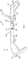
- Figure 1 is a view of a vegetation cutter comprising an embodiment of a shaft assembly according to the invention, in the partially extended mode;
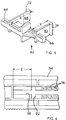
- Figure 2 is an enlarged plan view, partially in longitudinal section, of the embodiment of the shaft assembly of Figure 1.
- Figure 3 is a cross-section on line III-III of Figure 2, showing the locking ring in locked position;
- Figure 4 is a similar section to that of Figure 3, showing the locking ring in unlocked position.
- Figure 5 is a perspective view of the pin means and
- Figure 6 is a part side view of an alternative embodiment of shaft assembly.
- As can be seen from Figure 1, a vegetation cutter (10) comprises a lower housing (12) connected by a shaft assembly (14) to a handle assembly (16). The handle assembly (16) provides a switch (18) for selectively supplying electrical power to an electric motor (not shown) carried within the housing (12). For two-handed operation of the trimmer, a secondary handle (10) is mounted on the handle assembly (16). The lower housing (12) carries a cutting head rotatable about an axis passing through the housing (12) and the cutting line (12) extends into a cutting place which is substantially perpendicular to the axis of rotation of housing (12).
- The device can be adjusted in known manner from the trimming mode as shown in Figure 1 to the edging mode by rotation of the lower housing (12) through 180° relative to the handle assembly (16).
- The shaft assembly (14) comprises a first shaft part (26) and a second shaft part (28). The first shaft part (26) is of substantially cylindrical cross-section and comprises a lower section (30) which is adapted for attachment to the lower housing (12) and a upper section (32) of reduced cross-section.
- The first shaft part (26) comprises first and second mating parts (34), (36). A longitudinal slot (38), (40) extends along the upper portion of the length of each of the mating parts (34), (36), commencing at a point approximately half of the way along the length of the portion of reduced cross-section, and terminating close to the free end of that portion.
- The second shaft part (28) comprises a central section (42) of substantially cylindrical cross-section which terminates at its upper end in a handle assembly (16) and at its lower end with four deformable fingers (44), (44') (44'') (44'''). The four deformable fingers (44), (44'), (44'') and (44''') are arranged in two opposed pairs. The second shaft part (28) comprises first and second mating parts (46), (48) each of which is provided on its inner face with a pair of axially offset radial grooves (50), (52) one of which (50) extends from the centre line of the mating part (46), (48) in one direction as far as the outer edge and the second of which (52) extends from the centre line of the mating part (46), (48) in the opposite direction as far as the outer edge. Each of the grooves (50), (52) is formed by a pair of parallel upstanding ribs (54), (56) which project from the inner wall of the mating part (46, (48), and is terminated by a short axial rib at the centre line.
- The two mating parts (46), (48) are mirror images of each other, so that when they are assembled to form the second shaft portion (28), the first internal groove (50) extends over half of the internal circumference of the section (42) and the second internal groove (52) extends over the other half of the internal circumference of the section (42).
- The central section (42) of the second shaft portion (28) has an internal diameter which will accept the upper section (32) of the first shaft portion (26).
- The first shaft portion (26) is assembled from its two mating parts (34), (36), and a pin (62)and the pin (62) is trapped between these mating parts (34), (36) with a first arm (64) projecting through slot (38) and an opposite arm (66) projecting through slot (40).
- The pin (62) is free to move along the length of the matching longitudinal slots (38), (40).
- The two arms (64) (66), are offset from one another by the same amount as the radial grooves (50), (52) are relatively offset, so that when the first shaft portion (26) is inserted in the second shaft portion (28) the arms (64), (66) of the pin (62) engage in the radial grooves (50),(52) respectively.
- Relative axial movement of the first shaft portion (26) and the second shaft portion (28) is thus permitted as the pin (62) moves along the length of the longitudinal slots (38), (40). Relative radial movement of the first shaft portion (26) and the second shaft portion (28) is permitted as the pin (62) moves within the internal grooves (50), (52) over half of the internal circumference, and is constrained by the short axial ribs at the centre line.
- As can be seen from Figure 5, the pin (62) further comprises extension portions (68) and (70) of right angles to the arms (64) and (66), which terminate in projections (72) and (74) respectively. These projections (72), (74) are spaced by a distance (X), (Y) from the corresponding arm (64) and (66) respectively.
- A locking ring (78) is provided to clamp the deformable fingers (44), (44'), (44'') and (44''') in engagement with the first shaft part (26). The end of the second shaft part (28) which terminates in the deformable fingers is inserted within the ring (78).
- Cam surfaces (80), (80'), (80'') and (80''') are provided on the inner surface of locking ring (78) for engagement with the corresponding fingers (44), (44'), (44'') and (44''').
- A pair of internal axial ribs (not shown), are provided on the internal surface of the locking ring (78) close to the end of the ring remote from the cam surfaces (80), (80'), (80''), (80''') for engagement with corresponding external projections (not shown) on the second shaft portion (28) to limit the ability of the ring to rotate relative to the shaft portion.
- Figure 3 shows the locking ring (78) in the clamping position, in which the cam surfaces (80), (80'), (80''), (80''') are in engagement with the deformable fingers (44), (44'), (44'') and (44''') and clamping these fingers against the upper section (32) of the first shaft part (26).
- In the position shown in Figure 4, the locking ring (78) has been rotated relative to the first shaft part (26) and the fingers (44), (44'), (44'') and (44''') have been released from engagement with the first shaft part (26). The second shaft part (28) is thus free to rotate relative to the first shaft part (26).
- Notches (76) are provided on the internal surface of the first shaft portion (26) which, in co-operation with the projections (72) and (74), control unwanted relative axial movement of the first and second shaft portions (26), (28) when the locking ring (78) is released and provide an audible indication of the relative axial positions of the first and second shaft portions (26), (28)
- A spring (not shown) may be provided to bias the projections (72) and (74) away from each other and towards the notches (76).
- In an alternative embodiment of the shaft assembly according to the invention, provision is made for the shaft assembly either to be adjustable both in the axial and radial directions, as in the first embodiment or simply in the radial direction, to allow rotation of the head relative to the handle. It may be desirable to provide both alternative types of adjustment in a range of products, and to use the same clamshells for both models, thus reducing the cost of manufacture.
- In order to provide a shaft assembly according to the present invention in which the clamshell can be used for both models, the first and second mating parts (34) and (36) of the first shaft portion (26) are modified as shown in Figure 6. In one or each part, at the end of the slot (38), (40) remote from the free end of the upper section (32) are provided with a short cross groove (82) at a distance (Z) less than the pin (62) dimension (X) or (Y) from the end of the slot (38) or (40).
- If it is intended that the shaft portion (26) is for use in a shaft assembly which is adjustable both in the axial and radial directions, then a pin (62) as shown in Figure 5 is used and the assembly and operation are exactly as described for the first embodiment, the cross groove (82) having no effect. If however, the shaft portion (26) is for use in a shaft assembly which is only adjustable in the radial direction, then the pin (62) is replaced by an alternative design of pin in which the extension portions (68) and (70) are reduced in length and the projections (72) and (74) are increased in height, so that the distance between the projections (72) and (74) and the arms (64) and (66) respectively, is equal to or less than the distance (Z) defined above. This has the effect that when the shaft is first assembled, the projections (72) and (74) are trapped within the cross-grooves, and axial movement of the first shaft portion (26) relative to the second shaft portion (28) is no longer possible.
Claims (11)
the first shaft part is slideable and/or rotatable within the second shaft part;
pin means is trapped within the first shaft part and adapted to engage with co-operating receiving means in the second shaft part; and
clamp means is provided to secure the second shaft part relative to the first shaft part.
Applications Claiming Priority (2)
| Application Number | Priority Date | Filing Date | Title |
|---|---|---|---|
| GB939323110A GB9323110D0 (en) | 1993-11-09 | 1993-11-09 | Improved shaft assembly |
| GB9323110 | 1993-11-09 |
Publications (3)
| Publication Number | Publication Date |
|---|---|
| EP0653364A2 true EP0653364A2 (en) | 1995-05-17 |
| EP0653364A3 EP0653364A3 (en) | 1996-02-28 |
| EP0653364B1 EP0653364B1 (en) | 1999-01-07 |
Family
ID=10744902
Family Applications (1)
| Application Number | Title | Priority Date | Filing Date |
|---|---|---|---|
| EP94308031A Expired - Lifetime EP0653364B1 (en) | 1993-11-09 | 1994-11-01 | Improved shaft assembly |
Country Status (5)
| Country | Link |
|---|---|
| US (1) | US5662428A (en) |
| EP (1) | EP0653364B1 (en) |
| CA (1) | CA2135333C (en) |
| DE (1) | DE69415775T2 (en) |
| GB (1) | GB9323110D0 (en) |
Cited By (7)
| Publication number | Priority date | Publication date | Assignee | Title |
|---|---|---|---|---|
| EP0893045A1 (en) | 1997-07-23 | 1999-01-27 | McCULLOCH CORPORATION | Shaft telescoping and rotational adjustment mechanism for a lawn and garden tool |
| EP1020257A1 (en) * | 1999-01-18 | 2000-07-19 | ROBERT BOSCH GmbH | Trimmer handle |
| EP1068790A1 (en) * | 1999-07-14 | 2001-01-17 | Black & Decker Inc. | Vegetation trimming and edging device with adjustable head orientation |
| EP1360887A1 (en) * | 2002-05-10 | 2003-11-12 | Umbria del Villar, S.L. | Agricultural implement for clearing vegetation |
| EP1017545B1 (en) * | 1997-09-24 | 2006-11-29 | Robert Bosch Gmbh | Hand-held machine-tool having a front and a rear parts which are offset relative to the housing for two-hand use |
| EP2682236A3 (en) * | 2012-07-04 | 2016-07-06 | Robert Bosch Gmbh | Handheld machine tool positioning device |
| EP3275599A1 (en) * | 2016-07-25 | 2018-01-31 | Andreas Stihl AG & Co. KG | Assembly comprising a housing and guide tube, hand-held working machine comprising a housing and guide tube |
Families Citing this family (32)
| Publication number | Priority date | Publication date | Assignee | Title |
|---|---|---|---|---|
| US6006434A (en) * | 1997-09-30 | 1999-12-28 | Hoffco, Inc. | Quick-release component connector for lawn tool |
| US20020111817A1 (en) * | 2000-02-02 | 2002-08-15 | Cronin John E. | Network-based system and method for facilitating conception of inventions in a directed manner |
| USD450226S1 (en) | 2000-02-03 | 2001-11-13 | The Toro Company | Vegetation trimmer |
| US6439088B1 (en) | 2000-04-25 | 2002-08-27 | The Toro Company | Reconfigurable vegetation trimmer and method of use |
| SE524198C2 (en) * | 2002-11-19 | 2004-07-06 | Electrolux Ab | Motor-driven work tools eg. bar hedge shears with a locking mechanism for the angle adjustment between a cutting unit and a bar |
| US8186066B2 (en) * | 2002-11-19 | 2012-05-29 | Husqvarna Ab | Motor driven tool such as a pole hedge trimmer with a locking mechanism for the turnable cutting unit |
| US7134208B2 (en) * | 2002-12-23 | 2006-11-14 | Black & Decker Inc. | Ergonomic handle for vegetation trimmer |
| GB0417364D0 (en) * | 2004-08-04 | 2004-09-08 | Bosch Gmbh Robert | Garden tool adjustment |
| US7257909B2 (en) * | 2004-10-27 | 2007-08-21 | The Toro Company | Convertible yard tool |
| USD519127S1 (en) | 2004-10-27 | 2006-04-18 | The Toro Company | Housing for convertible yard tool |
| US7314096B2 (en) | 2004-10-27 | 2008-01-01 | The Toro Company | Adjustable handle for portable tool |
| USD524824S1 (en) | 2004-10-27 | 2006-07-11 | The Toro Company | Convertible yard tool |
| DE102004056877B4 (en) * | 2004-11-25 | 2006-10-12 | Mogatec Moderne Gartentechnik Gmbh | grass trimmer |
| GB0509745D0 (en) * | 2005-05-13 | 2005-06-22 | Black & Decker Inc | Vegetation trimmer |
| DE102005051886A1 (en) * | 2005-10-29 | 2007-05-03 | Andreas Stihl Ag & Co. Kg | Hand-held implement, e.g. brush cutter, has tool, drive motor for driving tool with guide rod whereby electrical insulation is arranged between housing and second end of guide rod |
| US20070169846A1 (en) * | 2006-01-20 | 2007-07-26 | Innovative Products For Life Inc. | Edger |
| US7739800B2 (en) * | 2006-10-24 | 2010-06-22 | Hurley Edward P | Combination blower, trimmer and edger for tending vegetation |
| USD566491S1 (en) | 2006-12-26 | 2008-04-15 | The Toro Company | Vegetation trimmer |
| DE102007015680A1 (en) * | 2007-03-31 | 2008-10-23 | Andreas Stihl Ag & Co. Kg | Shaft system for a portable hand-held implement and portable hand-held implement |
| ITMI20081125A1 (en) * | 2008-06-20 | 2009-12-21 | Lelio Codeluppi | BRUSH CUTTER PERFECTED WITH EXTENSIBLE DOUBLE JOINT SHAFT |
| US20100031515A1 (en) * | 2008-08-11 | 2010-02-11 | Edward Patrick Hurley | Grounds tool with means for transposable grips |
| US20100088902A1 (en) * | 2008-10-10 | 2010-04-15 | Edward Patrick Hurley | Handheld lawn tool |
| IT1395753B1 (en) * | 2009-09-16 | 2012-10-19 | Paem S N C Di Becchi Silvano E C | GRASS TRIMMER. |
| US8352312B2 (en) * | 2010-02-12 | 2013-01-08 | Es&S Innovations, Llc | System and method for controlling actions taken on voting devices |
| US9610678B2 (en) * | 2013-03-15 | 2017-04-04 | Mindflow Llc | Modular telescoping power pole and bar clamp/spreader tool |
| EP3046408A4 (en) | 2013-09-20 | 2017-09-20 | Todd Rader | Handle configuration for power implements |
| US20180014461A1 (en) * | 2016-07-15 | 2018-01-18 | Mary Brewer | Miniature Weed Trimming Assembly |
| US10688647B2 (en) * | 2017-05-19 | 2020-06-23 | The Toro Company | Lawn and garden tool with boom having adjustable length and detachable boom sections |
| ES2876200T3 (en) * | 2017-09-27 | 2021-11-12 | Globe Jiangsu Co Ltd | Ergonomic trimmers that have high operational safety |
| US11518018B2 (en) | 2019-01-21 | 2022-12-06 | Milwaukee Electric Tool Corporation | Power tool with non-conductive driveshaft |
| US11384719B2 (en) | 2019-03-15 | 2022-07-12 | Milwaukee Electric Tool Corporation | Fluid tank for a power tool |
| US11618149B2 (en) | 2019-04-26 | 2023-04-04 | Milwaukee Electric Tool Corporation | Telescoping tool with collapsible bearing assembly |
Family Cites Families (17)
| Publication number | Priority date | Publication date | Assignee | Title |
|---|---|---|---|---|
| US2821834A (en) * | 1954-10-26 | 1958-02-04 | Earle F Walker | Collapsible rake |
| US3150888A (en) * | 1962-05-08 | 1964-09-29 | Ingersoll Rand Co | Coupling means |
| US3442541A (en) * | 1966-11-25 | 1969-05-06 | Norco Inc | Releasable fastener |
| US3545431A (en) * | 1968-06-18 | 1970-12-08 | Hoffmann La Roche | Monitoring display |
| GB1302191A (en) * | 1969-02-14 | 1973-01-04 | ||
| US4052789A (en) * | 1976-12-02 | 1977-10-11 | Weed Eater, Inc. | Rotary cutting assembly |
| US4286675A (en) * | 1979-06-25 | 1981-09-01 | Beaird-Poulan Division Of Emerson Electric Co. | Narrow profile power handle for line trimmer and the like |
| DE3046286A1 (en) * | 1980-12-09 | 1982-07-08 | Vorwerk & Co Interholding Gmbh, 5600 Wuppertal | LATCHING FOR TELESCOPICOUS GUIDES |
| US4463498A (en) * | 1982-08-31 | 1984-08-07 | Everts Robert G | Coupling for flailing line trimmer handles |
| US4505040A (en) * | 1982-08-31 | 1985-03-19 | Everts Robert G | Coupling for interconnecting two handle portions of a power driven implement |
| JPS6078667U (en) * | 1983-11-04 | 1985-06-01 | アップリカ葛西株式会社 | Wheelbarrow handle height adjustment mechanism |
| US4654971A (en) * | 1985-09-13 | 1987-04-07 | Hudd Enterprises | Prunner with collapsible drive shaft and housing |
| JPH0531867Y2 (en) * | 1988-03-23 | 1993-08-17 | ||
| AU614548B2 (en) * | 1988-10-26 | 1991-09-05 | Tanaka Kogyo Co., Ltd. | Hand-held machine |
| US5088147A (en) * | 1989-08-08 | 1992-02-18 | Concorde Tool Corp. | Adjustable length handle for flat finishers |
| US5228202A (en) * | 1992-08-17 | 1993-07-20 | Greenlife Products Corp. | Extension handle for tree top pruners |
| US5417511A (en) * | 1993-08-09 | 1995-05-23 | Warden; Roland R. | Releasable lock for telescoping members |
-
1993
- 1993-11-09 GB GB939323110A patent/GB9323110D0/en active Pending
-
1994
- 1994-11-01 DE DE69415775T patent/DE69415775T2/en not_active Expired - Lifetime
- 1994-11-01 EP EP94308031A patent/EP0653364B1/en not_active Expired - Lifetime
- 1994-11-08 CA CA002135333A patent/CA2135333C/en not_active Expired - Lifetime
-
1996
- 1996-11-20 US US08/760,013 patent/US5662428A/en not_active Expired - Lifetime
Cited By (10)
| Publication number | Priority date | Publication date | Assignee | Title |
|---|---|---|---|---|
| EP0893045A1 (en) | 1997-07-23 | 1999-01-27 | McCULLOCH CORPORATION | Shaft telescoping and rotational adjustment mechanism for a lawn and garden tool |
| US5933966A (en) * | 1997-07-23 | 1999-08-10 | Mcculloch Corporation | Shaft telescoping and rotational adjustment mechanism for a lawn and garden tool |
| EP1017545B1 (en) * | 1997-09-24 | 2006-11-29 | Robert Bosch Gmbh | Hand-held machine-tool having a front and a rear parts which are offset relative to the housing for two-hand use |
| EP1020257A1 (en) * | 1999-01-18 | 2000-07-19 | ROBERT BOSCH GmbH | Trimmer handle |
| EP1068790A1 (en) * | 1999-07-14 | 2001-01-17 | Black & Decker Inc. | Vegetation trimming and edging device with adjustable head orientation |
| US6301866B1 (en) | 1999-07-14 | 2001-10-16 | Black & Decker Inc. | Vegetation trimming and edging device with adjustable head orientation |
| US6460319B2 (en) | 1999-07-14 | 2002-10-08 | Black & Decker Inc. | Vegetation trimming and edging device with adjustable head orientation |
| EP1360887A1 (en) * | 2002-05-10 | 2003-11-12 | Umbria del Villar, S.L. | Agricultural implement for clearing vegetation |
| EP2682236A3 (en) * | 2012-07-04 | 2016-07-06 | Robert Bosch Gmbh | Handheld machine tool positioning device |
| EP3275599A1 (en) * | 2016-07-25 | 2018-01-31 | Andreas Stihl AG & Co. KG | Assembly comprising a housing and guide tube, hand-held working machine comprising a housing and guide tube |
Also Published As
| Publication number | Publication date |
|---|---|
| GB9323110D0 (en) | 1994-01-05 |
| EP0653364A3 (en) | 1996-02-28 |
| US5662428A (en) | 1997-09-02 |
| CA2135333C (en) | 2003-07-08 |
| DE69415775D1 (en) | 1999-02-18 |
| CA2135333A1 (en) | 1995-05-10 |
| DE69415775T2 (en) | 1999-05-27 |
| EP0653364B1 (en) | 1999-01-07 |
Similar Documents
| Publication | Publication Date | Title |
|---|---|---|
| US5662428A (en) | Shaft assembly | |
| EP0893045B1 (en) | Shaft telescoping and rotational adjustment mechanism for a lawn and garden tool | |
| EP0893206B1 (en) | Apparatus for adjusting relative positions of first and second members, particularly referring to the relative position between a main handle and an auxiliary handle on a portable tool | |
| US5078557A (en) | Limit stops for a router depth of cut adjustment mechanism | |
| CA2225120C (en) | Rotary cutter | |
| US6272757B1 (en) | Adjustable guide shoe for reciprocating saw | |
| AU699070B2 (en) | Hedge trimmer with combination shearing and sawing blade assembly | |
| JP3207865B2 (en) | Portable circular saw | |
| US4316685A (en) | Plunge type router | |
| EP0657255A1 (en) | Improved electrically operated tool | |
| EP0428211B1 (en) | Shaving apparatus | |
| US4463544A (en) | Edger | |
| US4972583A (en) | Tool for stripping cables | |
| EP2575424B1 (en) | Handle system for a handheld power tool | |
| CA2198531A1 (en) | Multiple purpose compound action snips | |
| EP3189723B1 (en) | Vegetation cutting device with saw blade | |
| EP0646311A1 (en) | Improvements in or relating to vegetation cutters | |
| EP1415524B1 (en) | Trimmer | |
| EP2281430B1 (en) | Vegetation cutting tool with trimming and edging positions | |
| US4912847A (en) | Cutting tool for `entx`-type plastic conduit | |
| EP0703044A1 (en) | Adjustable connection | |
| FI84006C (en) | Gräsklippningssax | |
| CN112004403B (en) | Hand-held power tool in the form of a grass cutter or brush cutter | |
| EP0053129B1 (en) | Apparatus for cutting vegetation | |
| EP1059025A2 (en) | Motor-driven garden tool, particularly hedge trimmer |
Legal Events
| Date | Code | Title | Description |
|---|---|---|---|
| PUAI | Public reference made under article 153(3) epc to a published international application that has entered the european phase |
Free format text: ORIGINAL CODE: 0009012 |
|
| AK | Designated contracting states |
Kind code of ref document: A2 Designated state(s): BE CH DE FR GB IT LI NL SE |
|
| PUAL | Search report despatched |
Free format text: ORIGINAL CODE: 0009013 |
|
| AK | Designated contracting states |
Kind code of ref document: A3 Designated state(s): BE CH DE FR GB IT LI NL SE |
|
| 17P | Request for examination filed |
Effective date: 19960615 |
|
| 17Q | First examination report despatched |
Effective date: 19970319 |
|
| GRAG | Despatch of communication of intention to grant |
Free format text: ORIGINAL CODE: EPIDOS AGRA |
|
| GRAG | Despatch of communication of intention to grant |
Free format text: ORIGINAL CODE: EPIDOS AGRA |
|
| GRAH | Despatch of communication of intention to grant a patent |
Free format text: ORIGINAL CODE: EPIDOS IGRA |
|
| GRAH | Despatch of communication of intention to grant a patent |
Free format text: ORIGINAL CODE: EPIDOS IGRA |
|
| GRAA | (expected) grant |
Free format text: ORIGINAL CODE: 0009210 |
|
| AK | Designated contracting states |
Kind code of ref document: B1 Designated state(s): BE CH DE FR GB IT LI NL SE |
|
| PG25 | Lapsed in a contracting state [announced via postgrant information from national office to epo] |
Ref country code: SE Free format text: THE PATENT HAS BEEN ANNULLED BY A DECISION OF A NATIONAL AUTHORITY Effective date: 19990107 Ref country code: NL Free format text: LAPSE BECAUSE OF FAILURE TO SUBMIT A TRANSLATION OF THE DESCRIPTION OR TO PAY THE FEE WITHIN THE PRESCRIBED TIME-LIMIT Effective date: 19990107 Ref country code: LI Free format text: LAPSE BECAUSE OF FAILURE TO SUBMIT A TRANSLATION OF THE DESCRIPTION OR TO PAY THE FEE WITHIN THE PRESCRIBED TIME-LIMIT Effective date: 19990107 Ref country code: IT Free format text: LAPSE BECAUSE OF FAILURE TO SUBMIT A TRANSLATION OF THE DESCRIPTION OR TO PAY THE FEE WITHIN THE PRE;WARNING: LAPSES OF ITALIAN PATENTS WITH EFFECTIVE DATE BEFORE 2007 MAY HAVE OCCURRED AT ANY TIME BEFORE 2007. THE CORRECT EFFECTIVE DATE MAY BE DIFFERENT FROM THE ONE RECORDED.SCRIBED TIME-LIMIT Effective date: 19990107 Ref country code: CH Free format text: LAPSE BECAUSE OF FAILURE TO SUBMIT A TRANSLATION OF THE DESCRIPTION OR TO PAY THE FEE WITHIN THE PRESCRIBED TIME-LIMIT Effective date: 19990107 Ref country code: BE Free format text: LAPSE BECAUSE OF FAILURE TO SUBMIT A TRANSLATION OF THE DESCRIPTION OR TO PAY THE FEE WITHIN THE PRESCRIBED TIME-LIMIT Effective date: 19990107 |
|
| REG | Reference to a national code |
Ref country code: CH Ref legal event code: EP |
|
| REF | Corresponds to: |
Ref document number: 69415775 Country of ref document: DE Date of ref document: 19990218 |
|
| ET | Fr: translation filed | ||
| NLV1 | Nl: lapsed or annulled due to failure to fulfill the requirements of art. 29p and 29m of the patents act | ||
| REG | Reference to a national code |
Ref country code: CH Ref legal event code: PL |
|
| PLBE | No opposition filed within time limit |
Free format text: ORIGINAL CODE: 0009261 |
|
| STAA | Information on the status of an ep patent application or granted ep patent |
Free format text: STATUS: NO OPPOSITION FILED WITHIN TIME LIMIT |
|
| 26N | No opposition filed | ||
| REG | Reference to a national code |
Ref country code: GB Ref legal event code: IF02 |
|
| PGFP | Annual fee paid to national office [announced via postgrant information from national office to epo] |
Ref country code: DE Payment date: 20101126 Year of fee payment: 17 |
|
| PGFP | Annual fee paid to national office [announced via postgrant information from national office to epo] |
Ref country code: GB Payment date: 20101124 Year of fee payment: 17 |
|
| PGFP | Annual fee paid to national office [announced via postgrant information from national office to epo] |
Ref country code: FR Payment date: 20111128 Year of fee payment: 18 |
|
| GBPC | Gb: european patent ceased through non-payment of renewal fee |
Effective date: 20121101 |
|
| REG | Reference to a national code |
Ref country code: FR Ref legal event code: ST Effective date: 20130731 |
|
| REG | Reference to a national code |
Ref country code: DE Ref legal event code: R119 Ref document number: 69415775 Country of ref document: DE Effective date: 20130601 |
|
| PG25 | Lapsed in a contracting state [announced via postgrant information from national office to epo] |
Ref country code: DE Free format text: LAPSE BECAUSE OF NON-PAYMENT OF DUE FEES Effective date: 20130601 |
|
| PG25 | Lapsed in a contracting state [announced via postgrant information from national office to epo] |
Ref country code: GB Free format text: LAPSE BECAUSE OF NON-PAYMENT OF DUE FEES Effective date: 20121101 Ref country code: FR Free format text: LAPSE BECAUSE OF NON-PAYMENT OF DUE FEES Effective date: 20121130 |