EP2575424B1 - Handle system for a handheld power tool - Google Patents
Handle system for a handheld power tool Download PDFInfo
- Publication number
- EP2575424B1 EP2575424B1 EP10852598.1A EP10852598A EP2575424B1 EP 2575424 B1 EP2575424 B1 EP 2575424B1 EP 10852598 A EP10852598 A EP 10852598A EP 2575424 B1 EP2575424 B1 EP 2575424B1
- Authority
- EP
- European Patent Office
- Prior art keywords
- handle
- connecting part
- hand tool
- power driven
- protrusion
- Prior art date
- Legal status (The legal status is an assumption and is not a legal conclusion. Google has not performed a legal analysis and makes no representation as to the accuracy of the status listed.)
- Active
Links
- 230000007246 mechanism Effects 0.000 claims description 41
- 238000003780 insertion Methods 0.000 claims description 30
- 230000037431 insertion Effects 0.000 claims description 30
- 238000000034 method Methods 0.000 claims description 14
- 238000013138 pruning Methods 0.000 description 1
Images


Classifications
-
- B—PERFORMING OPERATIONS; TRANSPORTING
- B25—HAND TOOLS; PORTABLE POWER-DRIVEN TOOLS; MANIPULATORS
- B25F—COMBINATION OR MULTI-PURPOSE TOOLS NOT OTHERWISE PROVIDED FOR; DETAILS OR COMPONENTS OF PORTABLE POWER-DRIVEN TOOLS NOT PARTICULARLY RELATED TO THE OPERATIONS PERFORMED AND NOT OTHERWISE PROVIDED FOR
- B25F5/00—Details or components of portable power-driven tools not particularly related to the operations performed and not otherwise provided for
- B25F5/02—Construction of casings, bodies or handles
-
- A—HUMAN NECESSITIES
- A01—AGRICULTURE; FORESTRY; ANIMAL HUSBANDRY; HUNTING; TRAPPING; FISHING
- A01G—HORTICULTURE; CULTIVATION OF VEGETABLES, FLOWERS, RICE, FRUIT, VINES, HOPS OR SEAWEED; FORESTRY; WATERING
- A01G3/00—Cutting implements specially adapted for horticultural purposes; Delimbing standing trees
- A01G3/04—Apparatus for trimming hedges, e.g. hedge shears
- A01G3/047—Apparatus for trimming hedges, e.g. hedge shears portable
- A01G3/053—Apparatus for trimming hedges, e.g. hedge shears portable motor-driven
-
- Y—GENERAL TAGGING OF NEW TECHNOLOGICAL DEVELOPMENTS; GENERAL TAGGING OF CROSS-SECTIONAL TECHNOLOGIES SPANNING OVER SEVERAL SECTIONS OF THE IPC; TECHNICAL SUBJECTS COVERED BY FORMER USPC CROSS-REFERENCE ART COLLECTIONS [XRACs] AND DIGESTS
- Y10—TECHNICAL SUBJECTS COVERED BY FORMER USPC
- Y10T—TECHNICAL SUBJECTS COVERED BY FORMER US CLASSIFICATION
- Y10T29/00—Metal working
- Y10T29/49—Method of mechanical manufacture
- Y10T29/49826—Assembling or joining
- Y10T29/49863—Assembling or joining with prestressing of part
- Y10T29/49876—Assembling or joining with prestressing of part by snap fit
Definitions
- the present invention relates to a power driven hand tool comprising a detatchable handle.
- It also relates to a method for mounting and securing a handle to a power driven hand tool.
- Power driven hand tools such as, but not limited to, hedge trimmers, sometimes are provided with a handle, which is detachable from a main body of the tool. Further, this handle may also be rotatable with respect to the tool for providing ergonomic working positions in various working environments.
- the current systems for mounting a detachable handle on the power tool usually include some fastening components, such as screws or clips. These small components may easily get lost. Also, the assembly procedure may get time consuming if several fastening components need to be installed during the assembly. Further, fastening components such as screws require the use of a screwdriver or the like. Another problem with such systems is that, as these systems are used with power tools such as hedge trimmers that generate a lot of vibrations, the fastening components may loosen over a period of operating time, and ultimately the fastening components may detach from the tool.
- an objective is to provide an efficient system for mounting a detachable handle on a power driven hand tool.
- an objective is to provide devices and methods for simple and safe mounting of a detachable handle on a power driven hand tool without using external fastening components.
- the locking mechanism is automatic, no external fastening means are required. Thereby, the handle can be mounted on the power driven hand tool in a simple and time efficient way.
- the first rotational position of the handle relative to the connecting part is a non-operating position.
- the second position of the handle relative to the connecting part is located at one end of a predefined continuous angular range of positions, which comprises one or more operating positions. Thereby, the handle is always locked to the tool before it reaches an operating position.
- the one or more operating positions include a central position and the first rotational position is substantially an upside-down position of the handle in relation to the central position and to the connecting part.
- the front end of the handle has a substantially tubular shape and is provided with a protrusion extending outwards in a substantially radial direction.
- the connecting part is provided with a corresponding recess.
- the recess and the protrusion are arranged in such a way that the protrusion can slide in the recess at insertion of the handle into the connecting part. This makes insertion of the handle into the connecting part simple.
- the protrusion and the recess are adapted to restrict the position of the handle to a non-operating position in relation to the connecting part, when it is inserted into the connecting part. This way the user will not be mislead to operating the power driven hand tool when the handle is in its insertion position and not locked to the connecting part.
- the recess of the connecting part extends in a substantially axial direction of the connecting part.
- the snap locking mechanism is arranged in such a way that the handle can be rotated in the connecting part until the protrusion passes the snap locking mechanism. Further, on passing the snap locking mechanism the handle will reach a predefined continuous angular range of positions which includes one or more possible operating positions. As the handle reaches the range of positions including the operating positions upon passing the snap locking mechanism, it is clearly indicated to the user when the handle has reached this range.
- the snap locking mechanism is provided approximately 90° from the central operating position. Since many tools with a rotatable handle have two operating positions of the handle located 90° off the central position (one on each side of the central position), a snap locking mechanism located about 90° from the central position will be close to one of the lateral operating positions.
- the power driven hand tool is a hedge trimmer.
- the locking mechanism is automatic, no external fastening means are required. Thereby, the handle can be mounted on the power driven hand tool in a simple and time efficient way.
- the first rotational position of the handle relative to the connecting part is a non-operating position. Since the insertion position is not an operating position, the user is not likely to operate the tool when the handle is still in its insertion position and thus not locked to the connecting part. Thereby, a safe mounting of the handle on the tool is achieved.
- the second rotational position of the handle relative to the connecting part is located at one end of a predefined continuous angular range of positions, comprising one or more operating positions. Thereby, the handle is always locked to the tool before it reaches an operating position.
- the one or more operating positions include a central position and the first rotational position is substantially an upside-down position of the handle in relation to the central position and to the connecting part.
- the front end of the handle has a substantially tubular shape and is provided with a protrusion extending outwards in a substantially radial direction.
- the connecting part is provided with a corresponding recess.
- the recess and the protrusion are arranged in such a way that the protrusion can slide in the recess at insertion of the handle into the connecting part. This makes insertion of the handle into the connecting part simple.
- the protrusion and the recess are adapted to restrict the position of the handle at insertion into the connecting part to a non-operating position in relation to the connecting part. This way the user will not be mislead to operating the power driven hand tool when the handle is in its insertion position and not locked to the connecting part.
- the snap locking mechanism is arranged in such a way that the handle after insertion into the connecting part can be rotated in the connecting part such that the protrusion passes the snap locking mechanism. Further, on passing the snap locking mechanism the handle reaches the predefined continuous angular positions, which comprises one or more operating positions. As the handle reaches the range of positions including the operating positions upon passing the snap locking mechanism, it is clearly indicated to the user when the handle has reached this range.
- FIG. 1 illustrates a perspective view of a power driven hand tool 100, according to an embodiment of the present invention.
- the power driven hand tool 100 is a hedge trimmer.
- the present invention may also be used in other equipments such as, but not limited to, shears, chainsaws or other cutting or pruning tools that are provided with a detachable handle, without departing from the essence of the present invention.
- the power driven hand tool 100 may include a working member 102.
- the working member 102 may be a blade, a saw chain or the like. In the embodiment illustrated in FIG. 1 , the working member 102 is a cutting blade.
- the power driven hand tool 100 may also include a main body 104, which in turn may include a housing 106 and a base portion 108.
- the housing 106 may further include a drive unit (not shown), such as an engine or an electric motor. The drive unit may drive the working member 102 of the power driven hand tool 100.
- the power driven hand tool 100 may further include a handle 110.
- the handle 110 may be of any shape that provides ergonomic handling of the power driven hand tool 100. Further, the handle 110 may include various controls mounted on it for controlling the working of the power driven hand tool 100. The controls may include a throttle control, a mode control, an on/off control and the like.
- the handle 110 may be rotatable with respect to the power driven hand tool 100 for adapting to different working environments. Further, the handle 110 may be detachable from the power driven hand tool 100.
- a connecting part 112 may be provided for connecting the handle 110 with the main body 104.
- the connecting part 112 may be a separate part fixedly mounted on the main body 104 or an integral part of the main body 104. Further, as illustrated in FIG. 2 , the connecting part 112 may have a locking mechanism 208 for securing the handle 110 with the connecting part 112 and the main body 104. It may also include a related means for functionally connecting the controls provided on the handle 110 with the power driven hand tool 100.
- the handle 110 may have a central position in relation to the power driven hand tool 100 and to the connecting part 112.
- the handle 110 of the power driven hand tool 100 is positioned in its central position.
- the central position is a position of the handle 110 suited for cutting in a substantially horizontal plane.
- FIG. 2 illustrates a perspective view of the handle 110 and the connecting part 112 as seen from an angle before they are joined together, according to an embodiment of the present invention.
- the handle 110 is positioned in an insertion position in relation to the connecting part, referred to as a first rotational position, which in this embodiment is an up-side-down position in relation to the connecting part 112.
- a front end of the handle 110 may have a tubular shape, and a protrusion 202 extending outwards in a substantially radial direction.
- the handle 110 may have a protruding ring 204.
- the connecting part 112 may have a tubular shape at an inner side of its rear end, where it is connected to the handle 110, and a recess 206 corresponding to the protrusion 202 on the handle 110.
- the recess 206 may extend in a substantially axial direction of the tubularly shaped part of the connecting part 112.
- the recess 206 and the protrusion 202 may be arranged in such a way that the protrusion 202 can slide in the recess 206 at insertion of the handle 110 into the connecting part 112.
- the handle 110 and the connecting part 112 may have a plurality of protrusions and a plurality of corresponding recesses respectively.
- there may be only one protrusion on the handle 110 but either several recesses or one single recess which is wider than the width of the protrusion 202, so that several positions of the handle 110 are possible for insertion into the connecting part 112.
- the recess or recesses may extend in a direction which is not the axial direction of the tubularly shaped part of the connecting part 112.
- the recess may extend obliquely, so that the handle 110 is rotated during the insertion into the connecting part 112.
- the locking mechanism provided for securing the handle 110 to the connecting part 112 is an automatic locking mechanism and may be a snap locking mechanism 208.
- the snap locking mechanism 208 is located approximately 90° from the central position.
- the connecting part 112 may be provided with one or more snap locking mechanisms of a second type, here referred to as snap fasteners 210.
- the connecting part has one snap fastener 210 which is located 180° from the recess 206. Further, the snap fastener 210 may indicate that the handle 110 has been inserted far enough into the connecting part to be rotated inside the connecting part.
- FIG. 3 illustrates another perspective view of the handle 110 and the connecting part 112 as seen from an angle before they are joined together.
- the power driven hand tool 100 may have to be used in a variety of different operating areas and held at a plurality of different angles.
- the handle 110 of the power driven hand tool 100 may have to be adapted to be rotated.
- This figure illustrates different rotational positions 302, 304, 306, 308 and 310 of the handle 110 in relation to the connecting part 112, in which the power driven hand tool 100 can be operated.
- a latch device is normally provided for the locking in a selected rotational position.
- the latch device is not shown in the figures and will not be further described.
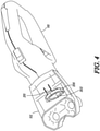
- FIG. 4 illustrates a perspective view of the handle 110 and the connecting part 112 where the connecting part is seen mainly from the bottom side of it to clearly illustrate the locking mechanism 208.
- the handle 110 is positioned in a first rotational position in relation to the connecting part 112 (and to the power driven hand tool 100 ) after insertion into the connecting part 112.
- the first rotational position is a position, in which the protrusion 202 can enter the recess 206 and the tubular part of the handle 110 can be inserted into the connecting part 112.
- the first rotational position is a non-operating position, i.e. a position which is not intended for operation of the power driven hand tool 100.
- the protrusion 202 and the recess 206 are adapted to restrict the rotational position of the handle 110 at insertion into the connecting part 112 to a non-operating position.
- the first, non-operational, rotational position may be substantially an upside-down position of the handle 110 with respect to the central position and to the connecting part 112. In this position the handle 110 does not provide an ergonomic grip for operating the power driven hand tool 100 and the user is not likely to start operating the power driven hand tool 100 in this position.
- the first, non-operating, rotational position may be one of a plurality of non-operating positions in which the handle 110 can be inserted into the connecting part 112. This may be achieved (as described above) by either providing several recesses 206 on the connecting part 112 or providing one recess 206 which is wide enough to provide a range of different non-operating positions.
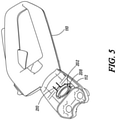
- FIG. 5 illustrates a perspective view of the handle 110 in a second position in relation to the connecting part 112 (and to the power driven hand tool 100 ) after it has been inserted into and rotated in the connecting part 112, according to an embodiment of the present invention.
- the second rotational position is the position, in which the handle 110 can be locked to the connecting part 112 by means of the automatic snap locking mechanism 208.
- the second rotational position is located at the end of a predefined range of positions of the handle including one or more operating positions, i.e. positions which are intended for operation of the power driven hand tool 100.
- the handle 110 reaches this predefined range of positions when the handle 110 has been rotated from the initial non-operating position to a position where the protrusion 202 has passed the snap locking mechanism 208.
- the second rotational position is located approximately 90° from the initial non-operating position.
- the second position may be very close to or essentially the same as one of the lateral positions
- the plurality of operating positions correspond to the rotational positions 302, 304, 306, 308 and 310 illustrated in FIG. 3 .
- the handle 110 on reaching the snap locking mechanism 208, may have to further traverse a predetermined rotational distance to reach the predefined continuous angular range of positions.
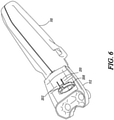
- FIG. 6 illustrates a perspective view of the handle 110 in the central position in relation to the connecting part 112 (and to the power driven hand tool 100 ) after it has been inserted into the connecting part 112 and rotated approximately 180°.
- this central position is one of the plurality of operating positions located within the predefined continuous angular range of positions. Further, at least one operating position may be present on either side of the central position, located approximately 90° from the central position, and adapted for performing the operation of the power driven hand tool 100 in a substantially vertical plane. The central position is adapted for performing the operation of the power driven hand tool 100 in a substantially horizontal plane.
- a tool such as a screw driver or the like, may be needed for removing the handle 110 from the connecting part 112 .
- the snap locking mechanism 208 may be adjusted for enabling the protrusion 202 to be rotated back past the snap locking mechanism 208.
- the tool may be used for adjusting the snap fastener 210 for enabling the protruding ring 204 to be slipped past the snap fastener 210 and out of the connecting part.
- This type of assembly eliminates the need for external fastening components such as, screws, and also enables the operation of the power driven hand tool 100 only when the handle 110 is properly secured on the power driven hand tool 100.
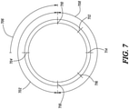
- FIG. 7 is a scheme for illustrating various non-operating and operating positions of the handle 110 in relation to the connecting part 112 (and to the power driven hand tool 100 ), according to an embodiment of the present invention.
- the power driven hand tool 100 may have a continuous range of non-operating positions 702, in which one non-operating position 704 is a preferred position for insertion of the handle 110 into the connecting part 112.
- the range of non-operating positions 702 may have an angular size of approximately 180°.
- the non-operating position 704 i.e. the first rotational position of the handle in relation to the connecting part 112, is substantially an upside-down position in relation to the central position 714.
- the handle needs to be rotated approximately 90° from the first rotational position for the protrusion 202 to pass the snap locking mechanism 208.
- the continuous angular range of positions 708 includes a plurality of operating positions 710, 712, 714, 716 and 718 that correspond to rotational positions 302, 304, 306, 308 and 310.
- the predefined continuous angular range of positions 708 has an angular size of approximately 180°.
- FIG. 8 is a flowchart illustrating a method 800 for mounting and securing the handle 110 on the power driven hand tool 100, according to an embodiment of the present invention.
- the connecting part 112 may be provided for connecting the handle 110 with the main body 104 of the power driven hand tool 100.
- the front end of the handle 110 may have a tubular shape and a protrusion 202, extending in a substantially radial direction.
- the connecting part 112 may have a tubular shape at the inner side of its rear end, where it is connected to the handle 110, and the recess 206 corresponding to the protrusion 202 on the handle 110.
- the recess 206 may extend in a substantially axial direction of the tube shaped part of the connecting part 112.
- the recess 206 and the protrusion 202 are arranged in such a way that the protrusion 202 may slide in the recess 206 at insertion of the handle 110 into the connecting part 112.
- the front end of the handle 110 is inserted into the rear end of the connecting part 112, in a first rotational position in relation to the connecting part 112 (and to the power driven hand tool 100 ).
- the first rotational position is a position, in which the protrusion 202 can enter the recess 206 and the tube shaped part of the handle 110 can be inserted into the connecting part 112.
- the first rotational position is a non-operational position 704 of the handle 110, i.e. a position which is not intended for operation of the power driven hand tool 100. Further, there may be a plurality of non-operating positions suitable for insertion of the handle 110 into the connecting part 112.
- the protrusion 202 and the recess 206 are adapted to restrict the rotational position of the handle 110 at insertion into the connecting part 112, to a non-operating position 704.
- the first, non-operating, rotational position may be substantially an upside-down position of the handle 110 with respect to the central position.
- the handle 110 may be rotated into the second rotational position in relation to the connecting part 112 (and to the power driven hand tool 100 ).
- the second rotational position is the position, in which the handle 110 is locked to the connecting part 112 by means of an automatic locking mechanism.
- the automatic locking mechanism is a snap locking mechanism 208.
- the second rotational position of the handle 110 is located at one end of a continuous angular range of positions 708.
- the continuous angular range of positions 708 include one or more operating positions.
- the one or more operating positions 710, 712, 714, 716 and 718 may include the central position.
- the snap locking mechanism 208 is arranged in such a way that the handle 110 can be rotated inside the connecting part 112, such that the protrusion 202 on the handle 110 passes the snap locking mechanism 208 and reaches the continuous angular range of positions 708, from the initial non-operating position.
Description
- The present invention relates to a power driven hand tool comprising a detatchable handle.
- It also relates to a method for mounting and securing a handle to a power driven hand tool.
- Power driven hand tools, such as, but not limited to, hedge trimmers, sometimes are provided with a handle, which is detachable from a main body of the tool. Further, this handle may also be rotatable with respect to the tool for providing ergonomic working positions in various working environments.
- Document
US 6 108 867 A discloses a power tool according to the preamble of claim 1. - The current systems for mounting a detachable handle on the power tool usually include some fastening components, such as screws or clips. These small components may easily get lost. Also, the assembly procedure may get time consuming if several fastening components need to be installed during the assembly. Further, fastening components such as screws require the use of a screwdriver or the like. Another problem with such systems is that, as these systems are used with power tools such as hedge trimmers that generate a lot of vibrations, the fastening components may loosen over a period of operating time, and ultimately the fastening components may detach from the tool.
- There is a need for an improved system for mounting a detachable handle on a handheld power tool, which will overcome the disadvantages of the existing systems.
- In view of the above, it is an objective to provide an efficient system for mounting a detachable handle on a power driven hand tool. In particular, an objective is to provide devices and methods for simple and safe mounting of a detachable handle on a power driven hand tool without using external fastening components.
- This objective is achieved by the invention as defined by claim 1.
- Since the locking mechanism is automatic, no external fastening means are required. Thereby, the handle can be mounted on the power driven hand tool in a simple and time efficient way.
- According to claim 2, the first rotational position of the handle relative to the connecting part is a non-operating position. An advantage with this is that a user would not think of operating the tool when the handle is still in its insertion position and thus not locked to the connecting part. Thereby a safe mounting of the handle on the tool is achieved.
- According to claim 3, the second position of the handle relative to the connecting part is located at one end of a predefined continuous angular range of positions, which comprises one or more operating positions. Thereby, the handle is always locked to the tool before it reaches an operating position.
- According to claim 4, the one or more operating positions include a central position and the first rotational position is substantially an upside-down position of the handle in relation to the central position and to the connecting part. With this design, it is clear to the user that the insertion position is not a position intended for working with the tool.
- According to claim 5, the front end of the handle has a substantially tubular shape and is provided with a protrusion extending outwards in a substantially radial direction. Further, the connecting part is provided with a corresponding recess. Also, the recess and the protrusion are arranged in such a way that the protrusion can slide in the recess at insertion of the handle into the connecting part. This makes insertion of the handle into the connecting part simple.
- According to claim 6, the protrusion and the recess are adapted to restrict the position of the handle to a non-operating position in relation to the connecting part, when it is inserted into the connecting part. This way the user will not be mislead to operating the power driven hand tool when the handle is in its insertion position and not locked to the connecting part.
- According to claim 7, the recess of the connecting part extends in a substantially axial direction of the connecting part. An advantage with this arrangement is that the handle is easily inserted as it is kept in the same rotational position until it is fully inserted into the connecting part.
- According to claim 8, the snap locking mechanism is arranged in such a way that the handle can be rotated in the connecting part until the protrusion passes the snap locking mechanism. Further, on passing the snap locking mechanism the handle will reach a predefined continuous angular range of positions which includes one or more possible operating positions. As the handle reaches the range of positions including the operating positions upon passing the snap locking mechanism, it is clearly indicated to the user when the handle has reached this range.
- According to claim 9, the snap locking mechanism is provided approximately 90° from the central operating position. Since many tools with a rotatable handle have two operating positions of the handle located 90° off the central position (one on each side of the central position), a snap locking mechanism located about 90° from the central position will be close to one of the lateral operating positions.
- According to claim 10, the power driven hand tool is a hedge trimmer.
- To solve the problem posed there is provided a method according to claim 11 for assembling a handle and a connecting part of a power driven hand tool according to claims 1 - 10.
- Since the locking mechanism is automatic, no external fastening means are required. Thereby, the handle can be mounted on the power driven hand tool in a simple and time efficient way.
- According to claim 12 the first rotational position of the handle relative to the connecting part is a non-operating position. Since the insertion position is not an operating position, the user is not likely to operate the tool when the handle is still in its insertion position and thus not locked to the connecting part. Thereby, a safe mounting of the handle on the tool is achieved.
- According to claim 13 the second rotational position of the handle relative to the connecting part is located at one end of a predefined continuous angular range of positions, comprising one or more operating positions. Thereby, the handle is always locked to the tool before it reaches an operating position.
- According to claim 14, the one or more operating positions include a central position and the first rotational position is substantially an upside-down position of the handle in relation to the central position and to the connecting part. With this design, it is clear to the user that the insertion position is not a position intended for working with the tool.
- According to claim 15, the front end of the handle has a substantially tubular shape and is provided with a protrusion extending outwards in a substantially radial direction. Further, the connecting part is provided with a corresponding recess. Also, the recess and the protrusion are arranged in such a way that the protrusion can slide in the recess at insertion of the handle into the connecting part. This makes insertion of the handle into the connecting part simple.
- According to claim 16, the protrusion and the recess are adapted to restrict the position of the handle at insertion into the connecting part to a non-operating position in relation to the connecting part. This way the user will not be mislead to operating the power driven hand tool when the handle is in its insertion position and not locked to the connecting part.
- According to claim 17, the snap locking mechanism is arranged in such a way that the handle after insertion into the connecting part can be rotated in the connecting part such that the protrusion passes the snap locking mechanism. Further, on passing the snap locking mechanism the handle reaches the predefined continuous angular positions, which comprises one or more operating positions. As the handle reaches the range of positions including the operating positions upon passing the snap locking mechanism, it is clearly indicated to the user when the handle has reached this range.
- The invention will in the following be described in more detail with reference to the enclosed drawings, wherein:
-
FIG. 1 illustrates a perspective view of a power driven hand tool, according to an embodiment of the present invention; -
FIG. 2 illustrates a perspective view of a handle and a connecting part as seen from one angle before they are joined together, according to an embodiment of the present invention; -
FIG. 3 illustrates a perspective view of the handle and the connecting part as seen from another angle before they are joined together, according to an embodiment of the present invention; -
FIG. 4 illustrates a perspective view of the handle in a first position, after insertion into the connecting part, according to an embodiment of the present invention; -
FIG. 5 illustrates a perspective view of the handle in a second position, according to an embodiment of the present invention; -
FIG. 6 illustrates a perspective view of the handle in a central position, according to an embodiment of the present invention; -
FIG. 7 is a schematic view illustrating various non-operating and operating positions for the handle mounted on the power driven hand tool, according to an embodiment of the present invention; and -
FIG. 8 is a flowchart illustrating a method for mounting the handle on the power driven hand tool, according to an embodiment of the present invention. - The present invention will be described more fully hereinafter with reference to the accompanying drawings, in which example embodiments of the invention incorporating one or more aspects of the present invention are shown. This invention may, however, be embodied in many different forms and should not be construed as limited to the embodiments set forth herein; rather, these embodiments are provided so that this disclosure will be thorough and complete, and will fully convey the scope of the invention to those skilled in the art. For example, one or more aspects of the present invention can be utilized in other embodiments and even other types of devices. In the drawings, like numbers refer to like elements.
-
FIG. 1 illustrates a perspective view of a power drivenhand tool 100, according to an embodiment of the present invention. In the exemplary embodiment shown inFIG. 1 , the power drivenhand tool 100 is a hedge trimmer. However, the present invention may also be used in other equipments such as, but not limited to, shears, chainsaws or other cutting or pruning tools that are provided with a detachable handle, without departing from the essence of the present invention. - Further, the power driven
hand tool 100 may include a workingmember 102. The workingmember 102 may be a blade, a saw chain or the like. In the embodiment illustrated inFIG. 1 , the workingmember 102 is a cutting blade. The power drivenhand tool 100 may also include amain body 104, which in turn may include ahousing 106 and abase portion 108. Thehousing 106 may further include a drive unit (not shown), such as an engine or an electric motor. The drive unit may drive the workingmember 102 of the power drivenhand tool 100. - The power driven
hand tool 100 may further include ahandle 110. Thehandle 110 may be of any shape that provides ergonomic handling of the power drivenhand tool 100. Further, thehandle 110 may include various controls mounted on it for controlling the working of the power drivenhand tool 100. The controls may include a throttle control, a mode control, an on/off control and the like. Thehandle 110 may be rotatable with respect to the power drivenhand tool 100 for adapting to different working environments. Further, thehandle 110 may be detachable from the power drivenhand tool 100. - In an embodiment of the present invention, a connecting
part 112 may be provided for connecting thehandle 110 with themain body 104. The connectingpart 112 may be a separate part fixedly mounted on themain body 104 or an integral part of themain body 104. Further, as illustrated inFIG. 2 , the connectingpart 112 may have alocking mechanism 208 for securing thehandle 110 with the connectingpart 112 and themain body 104. It may also include a related means for functionally connecting the controls provided on thehandle 110 with the power drivenhand tool 100. - Further, the
handle 110 may have a central position in relation to the power drivenhand tool 100 and to the connectingpart 112. InFIG. 1 , thehandle 110 of the power drivenhand tool 100 is positioned in its central position. Here, the central position is a position of thehandle 110 suited for cutting in a substantially horizontal plane. -
FIG. 2 illustrates a perspective view of thehandle 110 and the connectingpart 112 as seen from an angle before they are joined together, according to an embodiment of the present invention. Thehandle 110 is positioned in an insertion position in relation to the connecting part, referred to as a first rotational position, which in this embodiment is an up-side-down position in relation to the connectingpart 112. A front end of thehandle 110 may have a tubular shape, and aprotrusion 202 extending outwards in a substantially radial direction. Also, thehandle 110 may have aprotruding ring 204. Further, the connectingpart 112 may have a tubular shape at an inner side of its rear end, where it is connected to thehandle 110, and arecess 206 corresponding to theprotrusion 202 on thehandle 110. Therecess 206 may extend in a substantially axial direction of the tubularly shaped part of the connectingpart 112. Therecess 206 and theprotrusion 202 may be arranged in such a way that theprotrusion 202 can slide in therecess 206 at insertion of thehandle 110 into the connectingpart 112. - In alternative embodiments (not shown), the
handle 110 and the connectingpart 112 may have a plurality of protrusions and a plurality of corresponding recesses respectively. In an embodiment, there may be only one protrusion on thehandle 110, but either several recesses or one single recess which is wider than the width of theprotrusion 202, so that several positions of thehandle 110 are possible for insertion into the connectingpart 112. Also, in an embodiment, the recess or recesses may extend in a direction which is not the axial direction of the tubularly shaped part of the connectingpart 112. For example, the recess may extend obliquely, so that thehandle 110 is rotated during the insertion into the connectingpart 112. - The locking mechanism provided for securing the
handle 110 to the connectingpart 112 is an automatic locking mechanism and may be asnap locking mechanism 208. In a preferred embodiment, illustrated inFIG. 2 ,4 and5 , thesnap locking mechanism 208 is located approximately 90° from the central position. In an alternative embodiment, there may be twosnap locking mechanisms 208 of this type, each of them located approximately 90° off the central position on either side of the central position. - To achieve a stable connection between the
handle 110 and the connectingpart 112, the connectingpart 112 may be provided with one or more snap locking mechanisms of a second type, here referred to assnap fasteners 210. In an embodiment, as illustrated inFIG. 2 , the connecting part has onesnap fastener 210 which is located 180° from therecess 206. Further, thesnap fastener 210 may indicate that thehandle 110 has been inserted far enough into the connecting part to be rotated inside the connecting part. -
FIG. 3 illustrates another perspective view of thehandle 110 and the connectingpart 112 as seen from an angle before they are joined together. The power drivenhand tool 100 may have to be used in a variety of different operating areas and held at a plurality of different angles. Hence, thehandle 110 of the power drivenhand tool 100 may have to be adapted to be rotated. This figure illustrates differentrotational positions handle 110 in relation to the connectingpart 112, in which the power drivenhand tool 100 can be operated. For the locking in a selected rotational position a latch device is normally provided. The latch device is not shown in the figures and will not be further described. -
FIG. 4 illustrates a perspective view of thehandle 110 and the connectingpart 112 where the connecting part is seen mainly from the bottom side of it to clearly illustrate thelocking mechanism 208. Thehandle 110 is positioned in a first rotational position in relation to the connecting part 112 (and to the power driven hand tool 100) after insertion into the connectingpart 112. - The first rotational position is a position, in which the
protrusion 202 can enter therecess 206 and the tubular part of thehandle 110 can be inserted into the connectingpart 112. In a preferred embodiment of the present invention, the first rotational position is a non-operating position, i.e. a position which is not intended for operation of the power drivenhand tool 100. Theprotrusion 202 and therecess 206 are adapted to restrict the rotational position of thehandle 110 at insertion into the connectingpart 112 to a non-operating position. In an embodiment of the present invention, the first, non-operational, rotational position may be substantially an upside-down position of thehandle 110 with respect to the central position and to the connectingpart 112. In this position thehandle 110 does not provide an ergonomic grip for operating the power drivenhand tool 100 and the user is not likely to start operating the power drivenhand tool 100 in this position. - In an alternative embodiment of the present invention, the first, non-operating, rotational position may be one of a plurality of non-operating positions in which the
handle 110 can be inserted into the connectingpart 112. This may be achieved (as described above) by either providingseveral recesses 206 on the connectingpart 112 or providing onerecess 206 which is wide enough to provide a range of different non-operating positions. -
FIG. 5 illustrates a perspective view of thehandle 110 in a second position in relation to the connecting part 112 (and to the power driven hand tool 100) after it has been inserted into and rotated in the connectingpart 112, according to an embodiment of the present invention. The second rotational position is the position, in which thehandle 110 can be locked to the connectingpart 112 by means of the automaticsnap locking mechanism 208. In a preferred embodiment, the second rotational position is located at the end of a predefined range of positions of the handle including one or more operating positions, i.e. positions which are intended for operation of the power drivenhand tool 100. Thehandle 110 reaches this predefined range of positions when thehandle 110 has been rotated from the initial non-operating position to a position where theprotrusion 202 has passed thesnap locking mechanism 208. In the embodiment ofFIG. 5 , the second rotational position is located approximately 90° from the initial non-operating position. - In the illustrated embodiment, where there are two lateral operating positions located approximately 90° from the central position, the second position may be very close to or essentially the same as one of the lateral positions
- In one embodiment, the plurality of operating positions correspond to the
rotational positions FIG. 3 . In an alternative embodiment, thehandle 110, on reaching thesnap locking mechanism 208, may have to further traverse a predetermined rotational distance to reach the predefined continuous angular range of positions. -
FIG. 6 illustrates a perspective view of thehandle 110 in the central position in relation to the connecting part 112 (and to the power driven hand tool 100) after it has been inserted into the connectingpart 112 and rotated approximately 180°. In an embodiment, this central position is one of the plurality of operating positions located within the predefined continuous angular range of positions. Further, at least one operating position may be present on either side of the central position, located approximately 90° from the central position, and adapted for performing the operation of the power drivenhand tool 100 in a substantially vertical plane. The central position is adapted for performing the operation of the power drivenhand tool 100 in a substantially horizontal plane. - The different arrangements of various possible operating and non-operating positions will be further explained in conjunction with
FIG. 7 . - For removing the
handle 110 from the connecting part 112 a tool, such as a screw driver or the like, may be needed. By means of the tool thesnap locking mechanism 208 may be adjusted for enabling theprotrusion 202 to be rotated back past thesnap locking mechanism 208. Similarly, the tool may be used for adjusting thesnap fastener 210 for enabling the protrudingring 204 to be slipped past thesnap fastener 210 and out of the connecting part. - This type of assembly eliminates the need for external fastening components such as, screws, and also enables the operation of the power driven
hand tool 100 only when thehandle 110 is properly secured on the power drivenhand tool 100. -
FIG. 7 is a scheme for illustrating various non-operating and operating positions of thehandle 110 in relation to the connecting part 112 (and to the power driven hand tool 100), according to an embodiment of the present invention. The power drivenhand tool 100 may have a continuous range ofnon-operating positions 702, in which onenon-operating position 704 is a preferred position for insertion of thehandle 110 into the connectingpart 112. The range ofnon-operating positions 702 may have an angular size of approximately 180°. - In the illustrated embodiment, the
non-operating position 704, i.e. the first rotational position of the handle in relation to the connectingpart 112, is substantially an upside-down position in relation to thecentral position 714. - In an embodiment of the present invention, there may be a predefined continuous angular range of
positions 708 including one or more operating positions, which can be reached by rotating thehandle 110 inside the connectingpart 112 from the first rotational position and such that theprotrusion 202 passes thesnap locking mechanism 208. In a preferred embodiment, the handle needs to be rotated approximately 90° from the first rotational position for theprotrusion 202 to pass thesnap locking mechanism 208. The continuous angular range ofpositions 708 includes a plurality ofoperating positions rotational positions positions 708 has an angular size of approximately 180°. -
FIG. 8 is a flowchart illustrating amethod 800 for mounting and securing thehandle 110 on the power drivenhand tool 100, according to an embodiment of the present invention. As explained in previous figures, the connectingpart 112 may be provided for connecting thehandle 110 with themain body 104 of the power drivenhand tool 100. In an embodiment of the present invention, the front end of thehandle 110 may have a tubular shape and aprotrusion 202, extending in a substantially radial direction. Further, the connectingpart 112 may have a tubular shape at the inner side of its rear end, where it is connected to thehandle 110, and therecess 206 corresponding to theprotrusion 202 on thehandle 110. Therecess 206 may extend in a substantially axial direction of the tube shaped part of the connectingpart 112. Therecess 206 and theprotrusion 202 are arranged in such a way that theprotrusion 202 may slide in therecess 206 at insertion of thehandle 110 into the connectingpart 112. - In
step 802, the front end of thehandle 110 is inserted into the rear end of the connectingpart 112, in a first rotational position in relation to the connecting part 112 (and to the power driven hand tool 100). The first rotational position is a position, in which theprotrusion 202 can enter therecess 206 and the tube shaped part of thehandle 110 can be inserted into the connectingpart 112. In a preferred embodiment of the present invention, the first rotational position is anon-operational position 704 of thehandle 110, i.e. a position which is not intended for operation of the power drivenhand tool 100. Further, there may be a plurality of non-operating positions suitable for insertion of thehandle 110 into the connectingpart 112. Theprotrusion 202 and therecess 206 are adapted to restrict the rotational position of thehandle 110 at insertion into the connectingpart 112, to anon-operating position 704. In an embodiment of the present invention, the first, non-operating, rotational position may be substantially an upside-down position of thehandle 110 with respect to the central position. - Further, in
step 804 thehandle 110 may be rotated into the second rotational position in relation to the connecting part 112 (and to the power driven hand tool 100). The second rotational position is the position, in which thehandle 110 is locked to the connectingpart 112 by means of an automatic locking mechanism. In a preferred embodiment of the present invention, the automatic locking mechanism is asnap locking mechanism 208. Further, the second rotational position of thehandle 110 is located at one end of a continuous angular range ofpositions 708. The continuous angular range ofpositions 708 include one or more operating positions. In an embodiment of the present invention, the one ormore operating positions - In an embodiment of the present invention, the
snap locking mechanism 208 is arranged in such a way that thehandle 110 can be rotated inside the connectingpart 112, such that theprotrusion 202 on thehandle 110 passes thesnap locking mechanism 208 and reaches the continuous angular range ofpositions 708, from the initial non-operating position. - Though the above mentioned invention explains the working with respect to a hedge trimmer, a person skilled in the art may know that such a system may be easily implemented on other tools like, but not limited to, chainsaws.
- In the drawings and specification, there have been disclosed preferred embodiments and examples of the invention and, although specific terms are employed, they are used in a generic and descriptive sense only and not for the purpose of limitation, the scope of the invention being set forth in the following claims.
Claims (17)
- A power driven hand tool (100) comprising:a main body (104) comprising a housing (106) with a drive unit for driving a working member of the tool,a handle (110) for user operation of the tool, anda connecting part (112) for connecting the handle (110) with the mainbody (104),characterized in that
the handle (110) and the connecting part (112) are arranged in such a way that a front end of the handle (110) is insertable into a rear end of the connecting part (112) in a first rotational position in relation to the connecting part (112), and in such a way that the handle (110) is rotatable into a second rotational position in relation to the connecting part (112), in which second position the handle (110) is lockable to the connecting part (112) by means of an automatic locking mechanism, wherein the automatic locking mechanism is a snap locking mechanism. - A power driven hand tool (100) according to claim 1, wherein the first rotational position of the handle (110) relative to the connecting part (112) is a non-operating position (704).
- A power driven hand tool (100) according to any of claims 1-2, wherein the second rotational position of the handle (110) relative to the connecting part (112) is located at one end of a predefined continuous angular range of positions (708) and wherein the continuous angular range of positions (708) comprises one or more operating positions (710 - 718).
- A power driven hand tool (100) according to claim 3, wherein the one or more operating positions (710 - 718) comprise a central position, and wherein the first rotational position is substantially an upside-down position of the handle (110) in relation to the central position and to the connecting part (112).
- A power driven hand tool (100) according to any of claims 1-4, wherein the front end of the handle (110) has a substantially tubular shape and is provided with a protrusion (202) extending outwards in a substantially radial direction, the connecting part (112) is provided with a corresponding recess (206), and the recess (206) and the protrusion (202) are arranged in such a way that the protrusion (202) can slide in the recess (206) at insertion of the handle (110) into the connecting part (112).
- A power driven hand tool (100) according to claim 5, wherein the protrusion (202) and the recess (206) are adapted to restrict the position of the handle (110) at insertion into the connecting part (112) to a non-operating position (704) in relation to the connecting part (112).
- A power driven hand tool (100) according to any of claims 5-6, wherein the recess of the connecting part extends in a substantially axial direction of the connecting part.
- A power driven hand tool (100) according to claim 7, wherein the snap locking mechanism is arranged in such a way that the handle (110), after insertion into the connecting part (112), can be rotated such that the protrusion (202) passes the snap locking mechanism and thereby reaches a predefined continuous angular range of positions (708) including one or more possible operating positions (710 - 718).
- A power driven hand tool (100) according to claim 8, wherein the one or more operating positions comprise a central position, and the snap locking mechanism is provided approximately 90° from the central operating position.
- A power driven hand tool (100) according to any of claims 1-9, wherein the hand tool is a hedge trimmer.
- A method (800) of assembling a handle (110) and a connecting part (112) of a power driven hand tool (100) according to any of the previous claims, the method (800) comprising the steps of:- inserting a front end of the handle (110) into a rear end of the connecting part (112) in a first rotational position in relation to the connecting part (112); and- rotating the handle (110) into a second rotational position in relation to the connecting part (112), in which second position the handle (110) is lockable to the connecting part (112) by means of a snap locking mechanism.
- A method (800) according to claim 11, wherein the first rotational position of the handle (110) relative to the connecting part (112) is a non-operating position (704).
- A method (800) according to any of claims 11-12, wherein the second rotational position of the handle (110) relative to the connecting part (112) is located at one end of a predefined continuous angular range of positions (708) comprising one or more possible operating positions (710 - 718).
- A method (800) according to claim 13, wherein the one or more operating positions (710 - 718) comprise a central position, and wherein the first rotational position is substantially an upside-down position of the handle (110) in relation to the central position and to the connecting part (112).
- A method (800) according to any of claims 11-14, wherein the front end of the handle (110) has a substantially tubular shape and is provided with a protrusion (202) extending outwards in a substantially radial direction, and wherein the connecting part (112) is provided with a corresponding recess (206), and the recess (206) and the protrusion (202) are arranged in such a way that the protrusion (202) can slide in the recess (206) at insertion of the handle (110) into the connecting part (112).
- A method (800) according to claim 15, wherein the protrusion (202) and the recess (206) are adapted to restrict the position of the handle (110) at insertion into the connecting part (112) to a non-operating position (704) in relation to the connecting part (112).
- A method (800) according to claim 16, wherein the snap locking mechanism is arranged in such a way that the handle (110) after insertion into the connecting part (112) can be rotated such that the protrusion (202) passes the snap locking mechanism and thereby reaches a predefined continuous angular range of positions (708) comprising one or more possible operating positions (710 - 718).
Applications Claiming Priority (1)
| Application Number | Priority Date | Filing Date | Title |
|---|---|---|---|
| PCT/SE2010/050625 WO2011152765A1 (en) | 2010-06-04 | 2010-06-04 | Handle system for a handheld power tool |
Publications (3)
| Publication Number | Publication Date |
|---|---|
| EP2575424A1 EP2575424A1 (en) | 2013-04-10 |
| EP2575424A4 EP2575424A4 (en) | 2018-03-28 |
| EP2575424B1 true EP2575424B1 (en) | 2022-02-16 |
Family
ID=45066965
Family Applications (1)
| Application Number | Title | Priority Date | Filing Date |
|---|---|---|---|
| EP10852598.1A Active EP2575424B1 (en) | 2010-06-04 | 2010-06-04 | Handle system for a handheld power tool |
Country Status (5)
| Country | Link |
|---|---|
| US (1) | US9855650B2 (en) |
| EP (1) | EP2575424B1 (en) |
| JP (1) | JP2013533123A (en) |
| CN (1) | CN102933070B (en) |
| WO (1) | WO2011152765A1 (en) |
Families Citing this family (9)
| Publication number | Priority date | Publication date | Assignee | Title |
|---|---|---|---|---|
| US20130025135A1 (en) * | 2010-03-30 | 2013-01-31 | Husqvarna Ab | Hedge trimmer |
| DE102010054653B4 (en) * | 2010-12-15 | 2022-03-03 | Andreas Stihl Ag & Co. Kg | Hand-held hedge trimmer |
| US9205568B2 (en) * | 2011-10-31 | 2015-12-08 | Pacific Handy Cutter, Inc. | Ambidextrous utility knife |
| US9205569B2 (en) * | 2011-10-31 | 2015-12-08 | Pacific Handy Cutter, Inc. | Ambidextrous utility knife |
| USD721551S1 (en) * | 2013-09-18 | 2015-01-27 | Sears Brands, L.L.C. | Hedger |
| CN106625458A (en) * | 2013-12-17 | 2017-05-10 | 苏州宝时得电动工具有限公司 | Electric tool |
| JP6397793B2 (en) * | 2015-04-22 | 2018-09-26 | 株式会社マキタ | Chainsaw |
| EP3687278A4 (en) * | 2017-09-27 | 2020-08-26 | Changzhou Globe Co., Ltd. | Impact protecting member for a cutting tool |
| CN111093356B (en) * | 2017-12-06 | 2023-01-24 | 苏州宝时得电动工具有限公司 | Grass cutter |
Family Cites Families (57)
| Publication number | Priority date | Publication date | Assignee | Title |
|---|---|---|---|---|
| US3423781A (en) | 1967-10-25 | 1969-01-28 | Harry H Henson | Securement for mop or broom heads |
| US3847233A (en) | 1973-06-29 | 1974-11-12 | Black & Decker Mfg Co | Trigger mechanism for hand-operated power device providing automatic lock-off and manual lock-on operation |
| US4207675A (en) * | 1978-05-15 | 1980-06-17 | Clarence Burchell | Adjustable utility extension handle for electrically powered handtool |
| US5010615A (en) * | 1989-07-28 | 1991-04-30 | Patricia Carter | Hand-holdable tool having a detachable handle |
| DE4021277C2 (en) * | 1989-09-08 | 1998-07-23 | Stihl Maschf Andreas | Hand-held implement with adjustable handle |
| JP2524648B2 (en) | 1990-05-28 | 1996-08-14 | 松下電工株式会社 | Switchboard |
| US5112156A (en) * | 1991-05-02 | 1992-05-12 | Boyer Richard L | Tool handle/extension coupler |
| JPH0660315U (en) * | 1993-01-29 | 1994-08-23 | 株式会社共立 | Operating handle of brush cutter |
| SE510335C2 (en) | 1995-09-20 | 1999-05-10 | Electrolux Ab | Motor-driven hedge trimmer |
| US5875510A (en) * | 1996-09-27 | 1999-03-02 | Chesebrough-Pond's Usa Co., Division Of Conopco, Inc. | Replaceable head toothbrush |
| JP3822333B2 (en) * | 1997-05-14 | 2006-09-20 | 株式会社共立 | Handle device for power working machine |
| ES2235424T3 (en) * | 1998-12-31 | 2005-07-01 | C. & E. FEIN GMBH | ELECTRICAL TOOL, ESPECIALLY ANGULAR GRINDER. |
| US6266850B1 (en) * | 1999-04-16 | 2001-07-31 | Interdynamics, Inc. | Hand-held tool and adjustable handle for same |
| US6349443B1 (en) * | 1999-08-10 | 2002-02-26 | Playtex Products, Inc. | Bottle/nipple cleaning device |
| DE19941509A1 (en) * | 1999-08-31 | 2001-03-29 | Interconnectron Ges Fuer Ind S | Circular connectors for making electrical line connections |
| US6644969B2 (en) * | 1999-09-14 | 2003-11-11 | Nobel Biocare Ab | Snap-in healing cap and insertion tool |
| US6443675B1 (en) * | 2000-02-17 | 2002-09-03 | Roto Zip Tool Corporation | Hand-held power tool |
| US20060112804A1 (en) * | 2001-01-29 | 2006-06-01 | Dils Jeffrey M | Ergonomic miter saw handle |
| US6701622B2 (en) | 2001-04-20 | 2004-03-09 | Black & Decker Inc. | Handle mounting arrangement for a power tool |
| US6769494B2 (en) * | 2001-04-30 | 2004-08-03 | Powerqwest, Inc. | Combination line trimmer and edger |
| US8034026B2 (en) * | 2001-05-18 | 2011-10-11 | Deka Products Limited Partnership | Infusion pump assembly |
| US6912790B2 (en) * | 2001-12-03 | 2005-07-05 | Milwaukee Electric Tool Corporation | Handle arrangement for a reciprocating saw |
| US6973728B2 (en) * | 2002-04-04 | 2005-12-13 | The Toro Company | Filament trimmer with dual triggers |
| US20040148789A1 (en) * | 2002-08-20 | 2004-08-05 | Gist Leslie D. | Rotatable handle for reciprocating saws |
| US6769338B2 (en) * | 2002-10-16 | 2004-08-03 | Credo Technology Corporation | Multiple position switch handle with locking mechanism |
| DE10260466B4 (en) * | 2002-12-21 | 2014-07-03 | Andreas Stihl Ag & Co. Kg | Hand-held implement |
| US6889917B2 (en) * | 2003-03-10 | 2005-05-10 | S.C. Johnson & Son, Inc. | Cleaning device with universal motion quick disconnect head |
| GB2404550A (en) * | 2003-08-04 | 2005-02-09 | Black & Decker Inc | Latch mechanism for pivoting handle assembly of a power tool |
| ATE336162T1 (en) * | 2003-08-04 | 2006-09-15 | Black & Decker Inc | HANDLE ARRANGEMENT FOR A POWER TOOL |
| EP1504658B1 (en) * | 2003-08-04 | 2006-10-04 | BLACK & DECKER INC. | Pivoting handle assembly for power tool |
| US7101274B1 (en) * | 2003-10-31 | 2006-09-05 | Black & Decker Inc. | Method and circuit for inserting a picture into a video picture |
| TWI326579B (en) | 2003-11-28 | 2010-07-01 | Honda Motor Co Ltd | Power working machine |
| JP4467044B2 (en) * | 2003-11-28 | 2010-05-26 | 本田技研工業株式会社 | Power working machine |
| JP2005160306A (en) | 2003-11-28 | 2005-06-23 | Honda Motor Co Ltd | Power working machine |
| JP4421923B2 (en) * | 2004-03-22 | 2010-02-24 | 本田技研工業株式会社 | Power working machine |
| GB0418294D0 (en) * | 2004-08-17 | 2004-09-15 | Hartley Brian | Hedge trimmer |
| DE102004042735A1 (en) * | 2004-09-03 | 2006-03-09 | Robert Bosch Gmbh | Tool holder, adapter and system with a tool holder and an adapter |
| DE202005004316U1 (en) * | 2005-03-17 | 2006-07-27 | Dolmar Gmbh | implement |
| CN101203129B (en) * | 2005-06-13 | 2011-06-08 | 株式会社山彦 | Power hand tool |
| DE102006018072B4 (en) * | 2006-04-10 | 2016-08-11 | Andreas Stihl Ag & Co. Kg | hedge clippers |
| WO2008002994A2 (en) * | 2006-06-27 | 2008-01-03 | Prolabel, Inc. | Tool system replaceable heads and offset handle |
| US8065774B2 (en) * | 2006-10-26 | 2011-11-29 | Margco International, Llc | Paint brush with detachable head |
| CN201044581Y (en) * | 2007-01-11 | 2008-04-09 | 江苏鑫港企业有限公司 | Hedge machine |
| US8136254B2 (en) * | 2007-02-06 | 2012-03-20 | Mtd Products Inc | Split power tool with extension |
| US20080184568A1 (en) | 2007-02-06 | 2008-08-07 | Desa Ip, Llc | Split Power Tool |
| US7836546B2 (en) * | 2007-10-23 | 2010-11-23 | Samsung Gwangiu Electronics Co., Ltd. | Dust collecting unit for vacuum cleaner |
| CN201107933Y (en) * | 2007-10-29 | 2008-09-03 | 黄理 | Electric secateurs |
| EP2082848B1 (en) * | 2008-01-24 | 2013-04-10 | Robert Bosch Gmbh | An electrical device having a battery pack with an easy attachment and release mechanism |
| JP5068219B2 (en) | 2008-05-16 | 2012-11-07 | 株式会社マキタ | Power working machine |
| DE102008042111A1 (en) * | 2008-09-15 | 2010-03-18 | Hilti Aktiengesellschaft | Additional handle for a hand tool |
| SE532753C2 (en) * | 2008-09-16 | 2010-04-06 | Atlas Copco Tools Ab | Portable power tool with a handle with a power control key |
| US20100077898A1 (en) * | 2008-09-30 | 2010-04-01 | David Mitchell Smith | Adjustable pommel handle for power tool |
| DE102008056563B4 (en) * | 2008-11-10 | 2014-10-02 | Gerhard Weusthof | Power tool, in particular saw |
| EP2196084A3 (en) * | 2008-12-11 | 2010-11-10 | Hitachi Koki CO., LTD. | Hand-held engine-powered tool |
| US8156656B2 (en) * | 2009-05-07 | 2012-04-17 | Black & Decker Inc. | Hedgetrimmer with rotatable rear handle |
| US8393835B2 (en) * | 2009-06-16 | 2013-03-12 | Robert Bosch Gmbh | Detachable operating handle for a power tool |
| US20110247224A1 (en) * | 2010-04-09 | 2011-10-13 | Alltrade Tools Llc | Cable saw system |
-
2010
- 2010-06-04 WO PCT/SE2010/050625 patent/WO2011152765A1/en active Application Filing
- 2010-06-04 US US13/701,634 patent/US9855650B2/en active Active
- 2010-06-04 EP EP10852598.1A patent/EP2575424B1/en active Active
- 2010-06-04 JP JP2013513132A patent/JP2013533123A/en active Pending
- 2010-06-04 CN CN201080067242.2A patent/CN102933070B/en active Active
Also Published As
| Publication number | Publication date |
|---|---|
| CN102933070A (en) | 2013-02-13 |
| US20130097876A1 (en) | 2013-04-25 |
| WO2011152765A1 (en) | 2011-12-08 |
| US9855650B2 (en) | 2018-01-02 |
| EP2575424A4 (en) | 2018-03-28 |
| EP2575424A1 (en) | 2013-04-10 |
| JP2013533123A (en) | 2013-08-22 |
| CN102933070B (en) | 2015-05-20 |
Similar Documents
| Publication | Publication Date | Title |
|---|---|---|
| EP2575424B1 (en) | Handle system for a handheld power tool | |
| EP2319288B1 (en) | String head for a trimmer | |
| EP2263440B1 (en) | Coupling apparatus for coupling blade protector to tool body of gardening tool | |
| US11844317B2 (en) | Hedge trimmer | |
| EP2580954B1 (en) | Machine with main pole | |
| JP4550890B2 (en) | Equipment for pole hedge cutters, etc. | |
| US10084360B2 (en) | Electric working machine | |
| US11667027B2 (en) | Working machine | |
| EP3076778B1 (en) | Dual direction cutting device | |
| CN113226656B (en) | Electric working machine | |
| US9656380B2 (en) | Power tool with accessory change tool storage | |
| EP3718698B1 (en) | Handheld electrical power tool | |
| JP4813267B2 (en) | Electric mower | |
| US20100054853A1 (en) | Coupling element | |
| JP5986176B2 (en) | Handle system for handheld power tools | |
| US20230202017A1 (en) | Work tool and transmission system thereof | |
| EP4101598A1 (en) | Side handle for power tool | |
| KR20190097775A (en) | Grass eliminator | |
| US20170359963A1 (en) | Method of attaching a removable saw blade to a reciprocating hedge trimmer | |
| JP2014233215A (en) | Portable work machine |
Legal Events
| Date | Code | Title | Description |
|---|---|---|---|
| PUAI | Public reference made under article 153(3) epc to a published international application that has entered the european phase |
Free format text: ORIGINAL CODE: 0009012 |
|
| STAA | Information on the status of an ep patent application or granted ep patent |
Free format text: STATUS: REQUEST FOR EXAMINATION WAS MADE |
|
| 17P | Request for examination filed |
Effective date: 20121212 |
|
| AK | Designated contracting states |
Kind code of ref document: A1 Designated state(s): AL AT BE BG CH CY CZ DE DK EE ES FI FR GB GR HR HU IE IS IT LI LT LU LV MC MK MT NL NO PL PT RO SE SI SK SM TR |
|
| DAX | Request for extension of the european patent (deleted) | ||
| RA4 | Supplementary search report drawn up and despatched (corrected) |
Effective date: 20180228 |
|
| RIC1 | Information provided on ipc code assigned before grant |
Ipc: A01G 3/053 20060101AFI20180222BHEP Ipc: B25F 5/02 20060101ALI20180222BHEP Ipc: B25G 3/16 20060101ALI20180222BHEP |
|
| STAA | Information on the status of an ep patent application or granted ep patent |
Free format text: STATUS: EXAMINATION IS IN PROGRESS |
|
| 17Q | First examination report despatched |
Effective date: 20210426 |
|
| GRAP | Despatch of communication of intention to grant a patent |
Free format text: ORIGINAL CODE: EPIDOSNIGR1 |
|
| STAA | Information on the status of an ep patent application or granted ep patent |
Free format text: STATUS: GRANT OF PATENT IS INTENDED |
|
| INTG | Intention to grant announced |
Effective date: 20210910 |
|
| GRAS | Grant fee paid |
Free format text: ORIGINAL CODE: EPIDOSNIGR3 |
|
| GRAA | (expected) grant |
Free format text: ORIGINAL CODE: 0009210 |
|
| STAA | Information on the status of an ep patent application or granted ep patent |
Free format text: STATUS: THE PATENT HAS BEEN GRANTED |
|
| AK | Designated contracting states |
Kind code of ref document: B1 Designated state(s): AL AT BE BG CH CY CZ DE DK EE ES FI FR GB GR HR HU IE IS IT LI LT LU LV MC MK MT NL NO PL PT RO SE SI SK SM TR |
|
| REG | Reference to a national code |
Ref country code: GB Ref legal event code: FG4D |
|
| REG | Reference to a national code |
Ref country code: CH Ref legal event code: EP |
|
| REG | Reference to a national code |
Ref country code: DE Ref legal event code: R096 Ref document number: 602010068060 Country of ref document: DE |
|
| REG | Reference to a national code |
Ref country code: AT Ref legal event code: REF Ref document number: 1468313 Country of ref document: AT Kind code of ref document: T Effective date: 20220315 |
|
| REG | Reference to a national code |
Ref country code: IE Ref legal event code: FG4D |
|
| REG | Reference to a national code |
Ref country code: LT Ref legal event code: MG9D |
|
| REG | Reference to a national code |
Ref country code: NL Ref legal event code: MP Effective date: 20220216 |
|
| REG | Reference to a national code |
Ref country code: AT Ref legal event code: MK05 Ref document number: 1468313 Country of ref document: AT Kind code of ref document: T Effective date: 20220216 |
|
| PG25 | Lapsed in a contracting state [announced via postgrant information from national office to epo] |
Ref country code: SE Free format text: LAPSE BECAUSE OF FAILURE TO SUBMIT A TRANSLATION OF THE DESCRIPTION OR TO PAY THE FEE WITHIN THE PRESCRIBED TIME-LIMIT Effective date: 20220216 Ref country code: PT Free format text: LAPSE BECAUSE OF FAILURE TO SUBMIT A TRANSLATION OF THE DESCRIPTION OR TO PAY THE FEE WITHIN THE PRESCRIBED TIME-LIMIT Effective date: 20220616 Ref country code: NO Free format text: LAPSE BECAUSE OF FAILURE TO SUBMIT A TRANSLATION OF THE DESCRIPTION OR TO PAY THE FEE WITHIN THE PRESCRIBED TIME-LIMIT Effective date: 20220516 Ref country code: NL Free format text: LAPSE BECAUSE OF FAILURE TO SUBMIT A TRANSLATION OF THE DESCRIPTION OR TO PAY THE FEE WITHIN THE PRESCRIBED TIME-LIMIT Effective date: 20220216 Ref country code: LT Free format text: LAPSE BECAUSE OF FAILURE TO SUBMIT A TRANSLATION OF THE DESCRIPTION OR TO PAY THE FEE WITHIN THE PRESCRIBED TIME-LIMIT Effective date: 20220216 Ref country code: HR Free format text: LAPSE BECAUSE OF FAILURE TO SUBMIT A TRANSLATION OF THE DESCRIPTION OR TO PAY THE FEE WITHIN THE PRESCRIBED TIME-LIMIT Effective date: 20220216 Ref country code: ES Free format text: LAPSE BECAUSE OF FAILURE TO SUBMIT A TRANSLATION OF THE DESCRIPTION OR TO PAY THE FEE WITHIN THE PRESCRIBED TIME-LIMIT Effective date: 20220216 Ref country code: BG Free format text: LAPSE BECAUSE OF FAILURE TO SUBMIT A TRANSLATION OF THE DESCRIPTION OR TO PAY THE FEE WITHIN THE PRESCRIBED TIME-LIMIT Effective date: 20220516 |
|
| PG25 | Lapsed in a contracting state [announced via postgrant information from national office to epo] |
Ref country code: PL Free format text: LAPSE BECAUSE OF FAILURE TO SUBMIT A TRANSLATION OF THE DESCRIPTION OR TO PAY THE FEE WITHIN THE PRESCRIBED TIME-LIMIT Effective date: 20220216 Ref country code: LV Free format text: LAPSE BECAUSE OF FAILURE TO SUBMIT A TRANSLATION OF THE DESCRIPTION OR TO PAY THE FEE WITHIN THE PRESCRIBED TIME-LIMIT Effective date: 20220216 Ref country code: GR Free format text: LAPSE BECAUSE OF FAILURE TO SUBMIT A TRANSLATION OF THE DESCRIPTION OR TO PAY THE FEE WITHIN THE PRESCRIBED TIME-LIMIT Effective date: 20220517 Ref country code: FI Free format text: LAPSE BECAUSE OF FAILURE TO SUBMIT A TRANSLATION OF THE DESCRIPTION OR TO PAY THE FEE WITHIN THE PRESCRIBED TIME-LIMIT Effective date: 20220216 Ref country code: AT Free format text: LAPSE BECAUSE OF FAILURE TO SUBMIT A TRANSLATION OF THE DESCRIPTION OR TO PAY THE FEE WITHIN THE PRESCRIBED TIME-LIMIT Effective date: 20220216 |
|
| PG25 | Lapsed in a contracting state [announced via postgrant information from national office to epo] |
Ref country code: IS Free format text: LAPSE BECAUSE OF FAILURE TO SUBMIT A TRANSLATION OF THE DESCRIPTION OR TO PAY THE FEE WITHIN THE PRESCRIBED TIME-LIMIT Effective date: 20220616 |
|
| PG25 | Lapsed in a contracting state [announced via postgrant information from national office to epo] |
Ref country code: SM Free format text: LAPSE BECAUSE OF FAILURE TO SUBMIT A TRANSLATION OF THE DESCRIPTION OR TO PAY THE FEE WITHIN THE PRESCRIBED TIME-LIMIT Effective date: 20220216 Ref country code: SK Free format text: LAPSE BECAUSE OF FAILURE TO SUBMIT A TRANSLATION OF THE DESCRIPTION OR TO PAY THE FEE WITHIN THE PRESCRIBED TIME-LIMIT Effective date: 20220216 Ref country code: RO Free format text: LAPSE BECAUSE OF FAILURE TO SUBMIT A TRANSLATION OF THE DESCRIPTION OR TO PAY THE FEE WITHIN THE PRESCRIBED TIME-LIMIT Effective date: 20220216 Ref country code: EE Free format text: LAPSE BECAUSE OF FAILURE TO SUBMIT A TRANSLATION OF THE DESCRIPTION OR TO PAY THE FEE WITHIN THE PRESCRIBED TIME-LIMIT Effective date: 20220216 Ref country code: DK Free format text: LAPSE BECAUSE OF FAILURE TO SUBMIT A TRANSLATION OF THE DESCRIPTION OR TO PAY THE FEE WITHIN THE PRESCRIBED TIME-LIMIT Effective date: 20220216 Ref country code: CZ Free format text: LAPSE BECAUSE OF FAILURE TO SUBMIT A TRANSLATION OF THE DESCRIPTION OR TO PAY THE FEE WITHIN THE PRESCRIBED TIME-LIMIT Effective date: 20220216 |
|
| REG | Reference to a national code |
Ref country code: DE Ref legal event code: R097 Ref document number: 602010068060 Country of ref document: DE |
|
| PG25 | Lapsed in a contracting state [announced via postgrant information from national office to epo] |
Ref country code: AL Free format text: LAPSE BECAUSE OF FAILURE TO SUBMIT A TRANSLATION OF THE DESCRIPTION OR TO PAY THE FEE WITHIN THE PRESCRIBED TIME-LIMIT Effective date: 20220216 |
|
| PLBE | No opposition filed within time limit |
Free format text: ORIGINAL CODE: 0009261 |
|
| STAA | Information on the status of an ep patent application or granted ep patent |
Free format text: STATUS: NO OPPOSITION FILED WITHIN TIME LIMIT |
|
| 26N | No opposition filed |
Effective date: 20221117 |
|
| PG25 | Lapsed in a contracting state [announced via postgrant information from national office to epo] |
Ref country code: MC Free format text: LAPSE BECAUSE OF FAILURE TO SUBMIT A TRANSLATION OF THE DESCRIPTION OR TO PAY THE FEE WITHIN THE PRESCRIBED TIME-LIMIT Effective date: 20220216 |
|
| REG | Reference to a national code |
Ref country code: CH Ref legal event code: PL |
|
| REG | Reference to a national code |
Ref country code: BE Ref legal event code: MM Effective date: 20220630 |
|
| PG25 | Lapsed in a contracting state [announced via postgrant information from national office to epo] |
Ref country code: SI Free format text: LAPSE BECAUSE OF FAILURE TO SUBMIT A TRANSLATION OF THE DESCRIPTION OR TO PAY THE FEE WITHIN THE PRESCRIBED TIME-LIMIT Effective date: 20220216 |
|
| GBPC | Gb: european patent ceased through non-payment of renewal fee |
Effective date: 20220604 |
|
| PG25 | Lapsed in a contracting state [announced via postgrant information from national office to epo] |
Ref country code: LU Free format text: LAPSE BECAUSE OF NON-PAYMENT OF DUE FEES Effective date: 20220604 Ref country code: LI Free format text: LAPSE BECAUSE OF NON-PAYMENT OF DUE FEES Effective date: 20220630 Ref country code: IE Free format text: LAPSE BECAUSE OF NON-PAYMENT OF DUE FEES Effective date: 20220604 Ref country code: FR Free format text: LAPSE BECAUSE OF NON-PAYMENT OF DUE FEES Effective date: 20220630 Ref country code: CH Free format text: LAPSE BECAUSE OF NON-PAYMENT OF DUE FEES Effective date: 20220630 |
|
| PG25 | Lapsed in a contracting state [announced via postgrant information from national office to epo] |
Ref country code: GB Free format text: LAPSE BECAUSE OF NON-PAYMENT OF DUE FEES Effective date: 20220604 Ref country code: BE Free format text: LAPSE BECAUSE OF NON-PAYMENT OF DUE FEES Effective date: 20220630 |
|
| P01 | Opt-out of the competence of the unified patent court (upc) registered |
Effective date: 20230419 |
|
| PG25 | Lapsed in a contracting state [announced via postgrant information from national office to epo] |
Ref country code: IT Free format text: LAPSE BECAUSE OF FAILURE TO SUBMIT A TRANSLATION OF THE DESCRIPTION OR TO PAY THE FEE WITHIN THE PRESCRIBED TIME-LIMIT Effective date: 20220216 |
|
| PGFP | Annual fee paid to national office [announced via postgrant information from national office to epo] |
Ref country code: DE Payment date: 20230508 Year of fee payment: 14 |
|
| PG25 | Lapsed in a contracting state [announced via postgrant information from national office to epo] |
Ref country code: HU Free format text: LAPSE BECAUSE OF FAILURE TO SUBMIT A TRANSLATION OF THE DESCRIPTION OR TO PAY THE FEE WITHIN THE PRESCRIBED TIME-LIMIT; INVALID AB INITIO Effective date: 20100604 |