EP0653324A1 - Method for driving a vehicle hydrostatically - Google Patents
Method for driving a vehicle hydrostatically Download PDFInfo
- Publication number
- EP0653324A1 EP0653324A1 EP93117621A EP93117621A EP0653324A1 EP 0653324 A1 EP0653324 A1 EP 0653324A1 EP 93117621 A EP93117621 A EP 93117621A EP 93117621 A EP93117621 A EP 93117621A EP 0653324 A1 EP0653324 A1 EP 0653324A1
- Authority
- EP
- European Patent Office
- Prior art keywords
- hydraulic
- wheel
- drive
- transmission
- displacement volume
- Prior art date
- Legal status (The legal status is an assumption and is not a legal conclusion. Google has not performed a legal analysis and makes no representation as to the accuracy of the status listed.)
- Granted
Links
Images


Classifications
-
- B—PERFORMING OPERATIONS; TRANSPORTING
- B60—VEHICLES IN GENERAL
- B60K—ARRANGEMENT OR MOUNTING OF PROPULSION UNITS OR OF TRANSMISSIONS IN VEHICLES; ARRANGEMENT OR MOUNTING OF PLURAL DIVERSE PRIME-MOVERS IN VEHICLES; AUXILIARY DRIVES FOR VEHICLES; INSTRUMENTATION OR DASHBOARDS FOR VEHICLES; ARRANGEMENTS IN CONNECTION WITH COOLING, AIR INTAKE, GAS EXHAUST OR FUEL SUPPLY OF PROPULSION UNITS IN VEHICLES
- B60K17/00—Arrangement or mounting of transmissions in vehicles
- B60K17/34—Arrangement or mounting of transmissions in vehicles for driving both front and rear wheels, e.g. four wheel drive vehicles
- B60K17/356—Arrangement or mounting of transmissions in vehicles for driving both front and rear wheels, e.g. four wheel drive vehicles having fluid or electric motor, for driving one or more wheels
-
- B—PERFORMING OPERATIONS; TRANSPORTING
- B60—VEHICLES IN GENERAL
- B60K—ARRANGEMENT OR MOUNTING OF PROPULSION UNITS OR OF TRANSMISSIONS IN VEHICLES; ARRANGEMENT OR MOUNTING OF PLURAL DIVERSE PRIME-MOVERS IN VEHICLES; AUXILIARY DRIVES FOR VEHICLES; INSTRUMENTATION OR DASHBOARDS FOR VEHICLES; ARRANGEMENTS IN CONNECTION WITH COOLING, AIR INTAKE, GAS EXHAUST OR FUEL SUPPLY OF PROPULSION UNITS IN VEHICLES
- B60K23/00—Arrangement or mounting of control devices for vehicle transmissions, or parts thereof, not otherwise provided for
- B60K23/08—Arrangement or mounting of control devices for vehicle transmissions, or parts thereof, not otherwise provided for for changing number of driven wheels, for switching from driving one axle to driving two or more axles
- B60K23/0808—Arrangement or mounting of control devices for vehicle transmissions, or parts thereof, not otherwise provided for for changing number of driven wheels, for switching from driving one axle to driving two or more axles for varying torque distribution between driven axles, e.g. by transfer clutch
Definitions
- the invention relates to a method for hydrostatically driving a vehicle with at least two ideal axles, each having at least one drivable wheel, each drivable wheel being driven by at least one hydraulic motor connected to at least one hydraulic source and the drive power by a hydraulic motor via a transmission gear is transferred to the respective wheel.
- a hydrostatic drive in particular for carrying out the method, is also proposed.
- the drivable wheels of different axes are driven by transmission gears with different translations. If the load requirement drops, the drive of the axis with the largest gear ratio is decoupled, and if the load requirement drops further, the same procedure is followed with the remaining driving axes until, in extreme cases, the entire drive power is transferred from the axis with the lowest gear ratio.
- several axes are required for a fine gradation of the power to be transmitted to the ground.
- as many axles as possible with transmission gears that are graduated as finely as possible must be used in the vehicle. This increases the complexity and cost of the drive and the vehicle cannot be used in some areas of application due to the high number of axles.
- the invention is based on the technical problem of creating a method and an associated device for hydrostatic driving of a vehicle, with which the Vehicle can be used with different performance requirements and is simple and inexpensive to manufacture and operate.
- the speed can be increased even further by changing the transmission ratio and driving all drivable wheels, the vehicle now being driven by more axles than before the second limit load was reached.
- the translation of the transmission gear can be reduced, for example, when the second limit load is reached, so that the higher speed is achievable.
- This process can be repeated one or more times, depending on the ability to change the translation of the transmission gears, so that different moments of differentiated coordination can be transmitted to the ground with either a single-axis or multi-axis drive.
- the first and second limit loads can be determined both by external loads acting on the vehicle and by limit values defined within a vehicle control system. For example, higher speed requirements or higher torque load requirements are conceivable as limit load values.
- the solution according to the invention can also be used when decelerating the vehicle, for example by gradually changing down.
- the operation after the first driving state with reduced effective drive of the wheels saves at least one ideal axis energy and fuel and higher speeds can be achieved with the same ratio than with the drive of all drivable wheels. This is particularly advantageous in soil conditions where, for example, the same multi-axis drive is not required or is unfavorable.
- vehicles can generate large propulsive forces and manage gradients of over 60%. Even starting from a standstill is possible on these gradients.
- the effective drive of a driven wheel is particularly advantageously reduced by lowering the displacement volume of the hydraulic motor. This allows the drive of a wheel to be continuously reduced without changing the power applied by the hydraulic source.
- the power equalization with other driven wheels happens automatically and smoothly.
- the displacement volume is the sum of all the maximum volume changes in the pressure chambers that result from the movement of the displacement elements during a shaft revolution or a double horn. In the case of hydraulic motors, this term is synonymous with the swallowing capacity or in the case of hydraulic pumps, the term is synonymous with the delivery volume.
- the displacement volume can be changed, for example, by adjusting the swivel angle.
- the displacement volume of the hydraulic motors are essentially set to zero when changing the translation of the transmission gear. This enables load-free changing or shifting of the transmission gears.
- the transmission gears can be switched in stages.
- Both of the gear ratios fit together particularly well for a solution according to the invention, and they cover a large driving speed and torque load range evenly.
- Gear ratio i is the ratio of input speed to output speed or output torque to input torque.
- these gear ratios are very suitable for light off-road vehicles, in particular with a weight of up to 2 t.
- the displacement volume of the hydraulic source designed as a hydraulic pump and driven by a drive motor is essentially zero when the drive motor is idling and is increased when the drive motor speed increases. This relieves the load on the drive when the drive motor is idling.
- the drive motor speed increases, for example by pressing an accelerator pedal, the power is transmitted to the hydraulic motors and the wheels.
- the displacement volume of the hydraulic pump can be increased to the maximum in order to achieve maximum propulsive power of the vehicle.
- the direction of travel is reversed by reversing the hydraulic pump.
- the direction of travel can be reversed by a simple changeover process on a component, namely the hydraulic pump.
- the hydraulic motors are preferably set to zero displacement without current.
- the hydraulic motors can be set to maximum displacement at least initially for acceleration. This allows maximum torque of the wheel to be transmitted to the ground as driving force, so that the vehicle experiences maximum driving force. This enables the drive to meet the highest load requirements. Once the highest load forces have been overcome, the displacement volume can be reduced again.
- the displacement volume of the hydraulic motors is preferably reduced when the hydraulic pump has reached the maximum displacement volume.
- the driving force can be continuously reduced after a maximum starting torque.
- the displacement volume of a driven hydraulic motor is particularly advantageously set to be relatively lower than its nominal value in the hydraulic pump volume.
- the power output by the hydraulic pump is not absorbed by the displacement volumes of the hydraulic motors, so that an increased pressure is established between each hydraulic motor and the hydraulic pump. This is higher than would be necessary for constant travel, so that the excess torque on the wheel is available, for example, for the acceleration of the vehicle.
- the drive motor When a desired driving speed is reached, it is proposed to regulate the speed of the drive motor to a desired size by changing the displacement volume of hydraulic motors and / or hydraulic pumps.
- the drive motor can work in the area of optimal injection, that is, it runs with the best use of the fuel and optimal exhaust gas composition.
- the desired target speed can be stored, for example, in the driving electronics and can be aimed for by regulating hydraulic motors and / or hydraulic pumps.
- An essentially wear-free permanent brake is preferably activated for braking. This relieves the wear and tear of the vehicle's service brakes. This is particularly favorable, for example, when driving downhill for a longer period, in which the continuous brake takes over a significant portion of the braking power.
- a performance-reducing additional circuit is conceivable, for example, as a wear-free permanent brake.
- the displacement volume of an adjustable additional hydraulic pump coupled to the drive motor can expediently be changed.
- the braking effect of the continuous brake can be changed continuously.
- the auxiliary hydro pump delivers, for example, into an auxiliary power line, in which the power transmitted by the auxiliary hydro pump is removed.
- the auxiliary hydraulic pump and auxiliary power line are essentially wear-free.
- a pressure relief valve in an additional flow line, into which the additional hydraulic pump delivers, is preferably adjusted in order to change the braking effect of the permanent brake.
- the pressure relief valve is easily adjustable, for example via the driving electronics; the adjustment causes a change in the power consumption in the auxiliary power line so that it can simulate different driving resistances to the drive motor.
- the current delivered by the auxiliary hydro pump can be directed into the auxiliary power line when driving and can be directed into a working circuit during operation.
- the auxiliary hydraulic pump of the working circuit which acts as a hydraulic source, can simultaneously be used as a continuous brake during driving.
- the displacement volume of at least the hydraulic motor driving this wheel is reduced.
- the torque transferred to the ground is reduced by reducing the displacement volume; in extreme cases, the displacement volume of the hydraulic motor is set to zero.
- This method is also advantageous when decelerating the vehicle by utilizing the drag torque of the drive motor. If the drive drag torque is so large that a wheel tends to lock on the ground (negative slip), the displacement volume of the associated hydraulic motor is reduced to such an extent that the drive motor is pressed and its speed drops. In extreme cases, the displacement volume of the hydraulic motor is completely set to zero, i.e. no torque on the wheel, and the drive motor runs at idle. All hydraulic motors can be adjusted or only the hydraulic motor of the wheel that tends to lock.
- the ratio of the difference between the circumferential wheel speed and the effective vehicle speed to the circumferential wheel speed is defined as slip.
- a reference value is preferably formed from the speeds of the driven wheels, and the speed of each driven wheel is compared with the reference value and as a function of it the deviation of a rotational speed of a driven wheel from the reference value changes the displacement volume of the hydraulic motor of this wheel.
- the slip of a wheel can easily be determined, for example, via the driving electronics.
- the locking of the wheels and the spinning of the wheels is determined by calculation and then the displacement volume of the hydraulic motor is changed in order to reduce the slip.
- the arithmetic mean can be used as the reference value.
- the continuous brake can be switched off when braking with an anti-lock braking system.
- the permanent brake no longer develops a braking effect on the drive wheels, so that the effectiveness of the anti-lock braking system is not impaired.
- the drive motor is set to idle when braking with an anti-lock braking system. This reduces the braking effect due to the engine drag torque on the wheels, so that the anti-lock braking system remains unaffected in its effect.
- the displacement volumes of the hydraulic pump and / or hydraulic motors of the driven wheels are preferably set to zero. This minimizes the driving force transmitted to the wheels by the hydraulic pump and / or hydraulic motors, so that the effectiveness of the anti-lock braking system remains unaffected.
- a displacement volume of the hydraulic motors is conceivably assigned to a driving speed. This saves control circuits for determining the hydraulic motors, the driving states are mainly controlled via the drive motor, for example by adjusting the accelerator pedal by an operator, and possibly by adjusting the displacement volume of the hydraulic pump.
- a generic hydrostatic drive is assumed, with at least two ideal axes, each of which has at least one drivable wheel, each drivable wheel being connected to at least one hydraulic motor connected to at least one hydraulic source, and a transmission gear being arranged between each hydraulic motor and the associated wheel is.
- a hydrostatic drive of this type is also known from WO91 / 01899.
- the generic hydrostatic drive is characterized according to the invention in that the translation of the transmission gear can be changed. This increases the speed range of the drive and the propulsive force that can be achieved with it, regardless of the adjustment options for the hydraulic source and / or hydraulic motors.
- the transmission gear has switchable transmission stages.
- different areas can be defined in interaction with the adjustable hydraulic motors or the hydraulic source, which are covered by the adjustment options of the hydraulic motors or source at a fixed transmission ratio. These areas can be connected to one another by appropriate selection of the switching stages or at least overlap areas.
- This translation has proven to be favorable, for example, to achieve speeds of over 70 km / h with a crane vehicle with a conventional drive motor, which make the vehicle suitable for use on the motorway.
- This translation combination is particularly favorable for vehicles weighing up to 10 t.
- the transmission gear is preferably fully integrated into the wheel hub.
- the transmission gear can be accommodated in the wheel hub to save space, so that the space between the individual wheels or ideal axles can be used for load-bearing vehicle parts or other vehicle units.
- the transmission gear can expediently be a two-stage planetary gear.
- This gearbox is very small and compact and can achieve gear ratios of various combinations and sizes in this design.
- a planetary gear is particularly well suited as a wheel hub drive.
- the transmission gear has a switchable neutral position.
- the wheels can be completely separated from the rest of the drive, so that a torque-free wheel state can be switched independently of the operating state of the rest of the drive. This has proven to be particularly advantageous in the case of an anti-lock braking system, an anti-slip control or a drive motor drag torque control.
- the transmission gear has a switchable blocking position.
- the vehicle can only independent of additional braking devices are braked by switching the transmission gear.
- the blocking position can be used as a parking brake.
- the transmission gear can be provided with hydrostatic actuating means for changing the transmission ratio or shifting.
- the hydrostatic actuation means can be coupled to the hydrostatic drive or have their own hydrostatic energy source.
- the hydraulic source is advantageously connected to a drive motor via a transfer case.
- the drive motor drives the hydraulic source, which can be designed, for example, as a hydraulic pump, the power transmitted by the drive motor being converted into the desired sizes in front of the hydraulic source by the transfer case.
- the transfer case can be connected to at least one additional consumer.
- the drive motor can also serve, for example, as a drive for an implement.
- an adjustable hydraulic pump may possibly feed into an operating circuit or into an additional power line acting as an essentially wear-free permanent brake.
- the adjustable hydraulic pump can drive an implement as a hydraulic source or, for example, can have a stressful effect on the drive motor when the vehicle is being driven by a power-draining additional power line.
- the load from the auxiliary power line brakes the drive motor, which in turn has a braking effect on the travel drive due to its drag torque. For example, this relieves the service brake of the vehicle considerably when driving downhill continuously.
- the transfer case can expediently be connected to a feed pump of the travel circuit.
- the traction circuit is automatically supplied with sufficient hydraulic fluid via the feed pump when the drive motor is running.
- the feed pump preferably supplies a directional circuit of the hydraulic source. This ensures that the hydraulic source can be switched continuously while the drive motor is running. The direction of travel of a vehicle can be changed via the directional circuit.
- a drive motor 1 which is connected to a transfer case 2, is shown.
- the drive motor 1 is connected to an accelerator pedal 3. It has a starter ring gear 4, to which a tachometer 5 is directed.
- the transfer case 2 is connected on one drive train with an adjustable hydraulic pump 6 with two flow directions and on a second drive train with two series-connected additional hydraulic pumps with constant displacement and one flow direction.
- the hydraulic pump 6 is connected via hydraulic lines 8 to a total of four hydraulic motors 9 with variable displacement and two flow directions.
- Each hydraulic motor 9 is coupled to a wheel 11 via a variable transmission 10.
- Two wheels 11 each are located on an ideal axis 12.
- the hydraulic motors 9 of each ideal axis 12 are connected in parallel to those of the other ideal axis 12 and the hydraulic motors 9 of the same ideal axis 12 are in turn connected in parallel to one another.
- Each wheel 11 is individually driven by a hydraulic motor 9.
- the hydraulic motors 9, the hydraulic pump 6, the tachometer 5 and the accelerator pedal 3 are connected to a control unit 14 via control lines 13.
- the drive motor 1 is also connected to the transfer case 2, a tachometer 5 connected to a control unit 14 via a control line 13 recording the drive speed of the drive motor 1.
- the transfer case 2 is connected in a first drive train to a feed pump 15 and the hydraulic pump 6 acting as a hydraulic source. Feed pump 15 and hydraulic pump 6 are connected in series.
- the hydraulic pump 6 with an adjustable displacement volume and two flow directions is connected via hydraulic lines 8 to four hydraulic motors 9, each of which is connected to a wheel 11 via a transmission gear 10. Two each Wheels 11 are located on an ideal axis 12.
- the hydraulic motors 9 of two ideal axes 12 are connected in parallel to one another and the hydraulic motors 9 of the same ideal axis 12 are also connected in parallel to one another.
- the hydraulic motors 9 each have an adjustable displacement volume and two flow directions.
- Each hydraulic motor 9 is connected to an adjusting unit 17 for adjusting the displacement volume.
- the adjustment units 17 are connected to the control unit 14 via control lines 13.
- An output tachometer 18 is arranged between the transmission gear 10 and the hydraulic motor 9 and is connected to the control unit 14 via a control line 13.
- each 4/4-way valve 19 has a container feed line 20 and a pump feed line 21.
- the volume flow generated by the feed pump 15 is guided, on the one hand, via a feed line 22 and a check valve 23 into the supplying and discharging hydraulic line 8 of the hydraulic pump 6.
- a spring-loaded, continuously adjustable pressure relief valve 24 is connected to the feed line 22.
- the feed pump 15 is connected to a directional circuit 26 via a ratio pressure control valve 25.
- the ratio pressure control valve 25 is followed in the direction of the circuit 26 by an electromagnetically adjustable 4/3 directional switching valve which actuates a double-acting, double spring-loaded cylinder 28.
- the cylinder 28 is mechanically connected to the hydraulic pump 6 and controls the displacement volume and the flow direction of the hydraulic pump 6.
- a differential pressure measuring orifice 29 is connected to the ratio pressure control valve 25.
- an infinitely adjustable additional hydraulic pump 7 with a flow direction is arranged on the second drive train of transfer case 2.
- the additional hydraulic pump 7 delivers via a 3/2-way valve 30 either into a working circuit 31 or into an additional flow line 32.
- An electromagnetically adjustable pressure relief valve 33 and a cooler 34 are arranged on the additional flow line 32.
- the electromagnetically adjustable pressure relief valve 33 is connected to the control unit 14 via a control line 13.
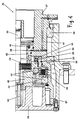
- FIGS. 3 and 4 each show a two-stage planetary gear 35 in a half section.
- the planetary gear 35 is designed as an integrated wheel hub gear and has a wheel carrier 36 on the outside to which a wheel 11 can be fastened.
- the planetary gear 35 is fixedly connected to a vehicle part via the hub part 37.
- the wheel carrier 36 is rotatably mounted on the hub part 37 via first roller bearings 38.
- a drive shaft 39 which is externally toothed at one end, is arranged centrally in the hub part 37.
- the drive shaft 39 serves as the sun of a first planetary stage with a first planet carrier 40 on which a first planet 41 is rotatably mounted.
- the first planet 41 engages on the inside in the drive shaft 39 and on the outside in a first ring gear 42.
- the first ring gear 42 is rotatably supported on the inside against the first planet carrier 40 and on the outside against the hub part 37 via second roller bearings 43.
- a first multi-plate clutch 44 is arranged between the first planet carrier 40 and the drive shaft 39.
- the first multi-plate clutch 44 is loaded by a first spring 45 and is therefore closed.
- the drive shaft 39, first planet carrier 40 and first planet 41 are firmly connected to one another.
- a first actuation chamber 46 can be pressurized via a first line 47, which runs through the hub part 37, so that the first spring 45 can be counteracted via a first intermediate part 48 and the first multi-plate clutch 44 can be relieved, that is to say opened.
- first planet 41, planet carrier 40 and drive shaft 39 are movable relative to one another.
- a second multi-plate clutch 49 is arranged between the first ring gear 42 and the hub part 37.
- the second multi-plate clutch 49 is relieved via a second spring 50 and a second intermediate part 51, so that the first ring gear 42 and the hub part 37 can be rotated relative to one another.
- a second actuation chamber 53 can be pressurized via a second line 52, so that the second spring 50 can be counteracted and the second multi-plate clutch 49 can be closed.
- the first ring gear 42 and the hub part 37 are connected to one another in a rotationally fixed manner.
- the first planet carrier 40 is toothed with a sun shaft 54 arranged in the extension of the drive shaft 39.
- the sun shaft 54 is in engagement with a second planet 55, which is rotatably mounted on a second planet carrier 56.
- the second planet carrier 56 is fixedly connected to the wheel carrier 36.
- the second planet 55 engages on the outside in a second ring gear 57 formed on the hub part 37.
- the first multi-plate clutch 44 is designed with 1.8 times the safety and the second multi-plate clutch 49 is designed with 1.5 times the safety.
- the drive shaft 39 is driven, for example, by a hydraulic motor 9, the first and second actuation chambers 46, 53 initially being depressurized. As a result, the first multi-plate clutch 44 is closed and the second multi-plate clutch 49 is open.
- Drive shaft 39, first planet carrier 40, first planet 41, first ring gear 42 and sun shaft 44 are connected to one another in a rotationally fixed manner.
- the drive torque is transmitted to the second planet carrier 56 only via the second planet 55, which is supported on the fixed second ring gear 57. This transmits the torque unchanged via the wheel carrier 36 to a wheel 11 to be driven.
- both actuation chambers 46, 53 are pressurized so that the first multi-plate clutch 44 is opened and the second multi-plate clutch 49 is closed.
- the first ring gear 42 is connected in a rotationally fixed manner to the fixed hub part 37 and a torque supplied by the drive shaft 39 is transmitted via the first planet 41, which is supported on the first ring gear 42, via the first planet carrier 40 to the sun shaft 54, which in turn transmits the driving force to the second planet 55, which is supported on the second ring gear 57 and transmits the force to the second planet carrier 56.
- the two planetary stages connected in series, transmit the drive torque to the second planet carrier and to a wheel 11 to be driven.
- both multi-plate clutches 44, 49 are closed and all transmission parts non-rotatably connected; the planetary gear blocked.
- the multi-plate clutch with lower security in this case the second multi-plate clutch 49, slips against its own frictional resistance at a very high moment load. This protects the gearbox from being destroyed by excessive torque.
- both multi-plate clutches 44, 49 are open and the planetary gear is in the neutral position; no moment is transmitted to the wheel 11.
- This two-stage planetary gear 35 can be used as a transmission gear 10 in the circuits of FIGS. 1 and 2.
- FIGS. 1 and 2 The functioning and mode of operation of the circuits of a hydrostatic drive according to the invention shown in FIGS. 1 and 2 are explained in more detail below.
- the drive motor 1 for example a diesel engine, drives the hydraulic pump 6 via the transfer case 2.
- the displacement volume of the hydraulic pump 6 is adjustable independently of the drive speed of the drive motor 1, for example by an electrically proportional adjustment.
- the hydraulic motors 9 are de-energized at displacement 0 and are set to maximum when the drive motor 1 starts. Depending on the driving speed and the drive motor speed, the hydraulic motors 9 reduce their displacement volume and thereby accelerate the vehicle. In order on the one hand to achieve high driving forces, for example for off-road driving, and on the other hand to achieve high speeds, for example for driving on the freeway, in addition to the adjustment ranges of hydraulic pump 6 and hydraulic motors 9, the mechanical translation of the transmission gear 10 is switched over. The hydraulic motors 9 are set to displacement volume 0 at the time of the transmission shift in order to switch without load.
- the vehicle starts with permanent all-wheel drive and therefore maximum traction. If a first driving state, for example a maximum speed of approximately 13 km / h, has been reached, the displacement volume of the hydraulic motors 9 of an ideal axis 12 is continuously reduced to zero, so that only the remaining ideal axis 12 drives.
- the hydraulic motors 9 of an ideal axis 12 drive until a second driving state is reached, for example up to a maximum driving speed of 26 km / h.
- the displacement volume of the hydraulic motors 9 of an ideal axis 12 is in turn reduced and set to zero, so that the hydraulic motors of an ideal axis 12 now drive. This will result in a maximum speed a very good efficiency of up to 75 km / h with good fuel consumption values.
- the driving through of these driving states can be repeated as often as required depending on the number of gear ratios of the transmission gears 10 or, for example, can also be carried out for reversing when the hydraulic pump delivery flow is reversed.
- control unit 14 which measures the speeds of the hydraulic motors 9 via the output tachometer 18 and measures the drive speed of the drive motor 1 via the tachometer 5.
- the displacement volume of the hydraulic motors 9 and the hydraulic pump 6 can be changed via the control unit 14.
- the elements connected via control lines 13, such as, for example, the differential pressure valves 24, 33 or the ratio pressure control valve 25 can also be controlled. The same applies to all switchable valves 19, 27.30.
- the engine speed of the drive motor 1 is increased by actuating the accelerator pedal 3, so that the displacement volume of the hydraulic pump 6 is increased.
- the hydraulic motors 9 initially have maximum displacement volumes, but are reset to smaller displacement volumes at maximum displacement volume of the hydraulic pump 6.
- the displacement volumes of the hydraulic motors 9 hurry ahead of their nominal value of the pump delivery volume to such an extent that the drive motor 1 is pressed to a certain extent relative to its nominal speed.
- an increased pressure than would be necessary for the current constant travel is generated between the hydraulic pump 6 and hydraulic motors 9, so that excess torque is available on the wheel 11 for the acceleration.
- the accelerator pedal If the accelerator pedal is reduced in a range of 100% to 30% load, the vehicle starts rolling and is slowed down by the driving resistance.
- the speed of the drive motor 1 drops to a new setpoint and the hydraulic motors 9 are adjusted to smaller displacement volumes. If the driving speed of the new target speed of the drive motor 1 is reached, the hydraulic pump 6 builds up a high pressure again and the hydraulic motors regulate the drive speed again to a new target value.
- the accelerator pedal 3 is reduced in a range from 30% to 0% load, the driving resistances and the drag torque of the drive motor 1 are braked.
- the displacement volumes of the hydraulic motors 9 are increased proportionally, so that the drag torque of the drive motor 1 is increased.
- the mean value with which the individual speeds are compared is formed from the speeds measured by output speed meters 18. If a wheel speed deviates too much from the mean value, the respective drive torque is reduced by the control unit 14 by reducing the displacement volume until the speed is again adjusted to the mean value is. This enables traction control to be implemented.
- a wear-free permanent brake can optionally be activated.
- Part of the drive power of the drive motor 1 is conducted via the transfer case 2 to the auxiliary hydraulic pump 7, which delivers into the auxiliary power line 32 while driving.
- the pressure that the hydraulic pump can build up in the additional flow line 32 can be limited via the pressure limiting valve 33.
- the cooler 34 dissipates the heat generated.
- By adjusting the displacement volume of the additional hydraulic pump 7, the drive power output via the additional power line 32 is varied.
- This drive power has an inhibiting effect on the drive motor 1 and is transferred to the hydraulic motors 9 via an increased engine drag torque. This brakes the hydrostatic drive.
- the permanent brake is switched off, for example by reducing the displacement volume of the additional hydraulic pump 7, and the drive motor 1 is set to idle.
- the hydraulic pump 6 and the hydraulic motors 9 are both set to zero displacement.
- the feed pump 15 In order to constantly supply the hydraulic lines 8 connected to the hydraulic pump 6 with sufficient hydraulic fluid, the feed pump 15, via the feed line 22 and the check valves 23, constantly ensures a sufficient pressure level which optimally fills the hydraulic lines 8. About the pressure relief valve 24 of the Feed pump 15 in the feed line 22 buildable pressure set.
- the volume flow conveyed by the feed pump 15 is measured via the differential pressure measuring orifice 29.
- the cylinder 28 is actuated via the 4/3 directional switching valve 27.
- the flow direction of the pump can be controlled via the cylinder 28 and possibly the displacement volume of the hydraulic pump 6 can also be set.
- the cylinder 28 can be controlled via the ratio pressure control valve 25 such that the displacement volume of the hydraulic pump 6 is controlled as a function of the speed of the drive motor 1.
- the volume flow generated by the feed pump 15 and measured via the differential pressure measuring orifice 29 is the reference measure for the speed-dependent control.
- control unit 14 can assign exactly one displacement volume of each hydraulic motor 9 to each driving speed.
- the hydrostatic drive is operated with a motor control.
- a corresponding motor control can be superimposed on this motor control, at least in some areas, whereby the drive motor 1 is influenced in certain load requirements and operating states by regulating the displacement volumes of the hydraulic motors 9 and / or the hydraulic pump 6.
- the entire drive power of the drive motor 1 is transferred to the auxiliary hydraulic pump 7 via the transfer case 2.
- the auxiliary hydraulic pump 7 conveys the entire volume flow into the working circuit 31.
- Working devices such as a telescopic arm, a shovel, a cable winch or the like, are actuated via the working circuit 31.
- the hydrostatic travel drive can be completely decoupled from the drive via the transfer case 2.
- this is also the case can be reached by idle position of the transmission gear or zeroing the displacement volumes of hydraulic pump 6 or hydraulic motors 9.
Abstract
Description
Die Erfindung bezieht sich auf ein Verfahren zum hydrostatischen Antreiben eines Fahrzeugs mit wenigstens zwei ideellen Achsen, die jeweils wenigstens ein antreibbares Rad aufweisen, wobei jedes antreibbare Rad von wenigstens einem mit wenigstens einer Hydraulikquelle verbundenen Hydromotor angetrieben wird und die Antriebsleistung von einem Hydromotor über ein Übersetzungsgetriebe auf das jeweilige Rad übertragen wird. Ebenso wird ein hydrostatischer Antrieb, insbesondere zum Durchführen des Verfahrens, vorgeschlagen.The invention relates to a method for hydrostatically driving a vehicle with at least two ideal axles, each having at least one drivable wheel, each drivable wheel being driven by at least one hydraulic motor connected to at least one hydraulic source and the drive power by a hydraulic motor via a transmission gear is transferred to the respective wheel. A hydrostatic drive, in particular for carrying out the method, is also proposed.
Bei einem aus der WO 91/01899 bekannten Verfahren der oben genannten Gattung werden die antreibbaren Räder unterschiedlicher Achsen von Übersetzungsgetrieben mit unterschiedlichen Übersetzungen angetrieben. Bei sinkendem Lastbedarf wird der Antrieb der Achse mit der größten Übersetzung abgekoppelt und bei weiter sinkender Lastanforderung mit den verbleibenden antreibenden Achsen analog verfahren, bis im Extremfall die gesamte Antriebsleistung von der Achse mit der kleinsten Übersetzung übertragen wird. Nachteiligerweise sind hierbei mehrere Achsen für eine feine Abstufung der auf den Untergrund zu übertragenden Leistung erforderlich. Um bei verschiedener Lastanforderung die Leistung auf den Boden zu übertragen und sowohl hohe Momente als auch große Fahrgeschwindigkeiten zu erreichen, müssen möglichst viele Achsen mit möglichst fein gegeneinander abgestuften Übersetzungsgetrieben in dem Fahrzeug eingesetzt werden. Dadurch steigen Komplexität und Kosten des Antriebes und das Fahrzeug kann aufgrund hoher Achszahlen in manchen Anwendungsbereichen nicht eingesetzt werden.In a method of the aforementioned type known from WO 91/01899, the drivable wheels of different axes are driven by transmission gears with different translations. If the load requirement drops, the drive of the axis with the largest gear ratio is decoupled, and if the load requirement drops further, the same procedure is followed with the remaining driving axes until, in extreme cases, the entire drive power is transferred from the axis with the lowest gear ratio. Disadvantageously, several axes are required for a fine gradation of the power to be transmitted to the ground. In order to transmit the power to the ground with different load requirements and to achieve both high torques and high driving speeds, as many axles as possible with transmission gears that are graduated as finely as possible must be used in the vehicle. This increases the complexity and cost of the drive and the vehicle cannot be used in some areas of application due to the high number of axles.
Der Erfindung liegt das technische Problem zugrunde, ein Verfahren und eine zugehörige Vorrichtung zum hydrostatischen Antreiben eines Fahrzeuges zu schaffen, mit denen das Fahrzeug bei unterschiedlichen Leistungsanforderungen verwendbar ist und einfach und kostengünstig herzustellen und zu betreiben ist.The invention is based on the technical problem of creating a method and an associated device for hydrostatic driving of a vehicle, with which the Vehicle can be used with different performance requirements and is simple and inexpensive to manufacture and operate.
Dieses technische Problem wird erfindungsgemäß dadurch gelöst, daß die antreibbaren Räder zunächst mit einer gleichen ersten Übersetzung der Übersetzungsgetriebe angetrieben werden, bei Erreichen einer ersten Grenzlast der effektive Antrieb der Räder von wenigstens einer ideellen Achse vermindert wird und bei Erreichen einer zweiten Grenzlast die Übersetzung der Übersetzungsgetriebe geändert wird und zumindest die vor der ersten Grenzlast angetriebenen Räder gleich angetrieben werden.This technical problem is solved according to the invention in that the drivable wheels are first driven with the same first transmission ratio of the transmission gears, the effective drive of the wheels is reduced by at least one ideal axis when a first limit load is reached and the transmission ratio of the transmission gears is reached when a second limit load is reached is changed and at least the wheels driven before the first limit load are driven equally.
Durch das anfängliche Antreiben der Räder mit einer gleichen ersten Übersetzung übertragen alle Räder zu Beginn den gleichen Leistungsanteil auf den Boden. Dadurch ist bei höchster Lastanforderung, zum Beispiel beim Anfahren, maximale Antriebsleistung gleichmäßig auf den Untergrund übertragbar, so daß das Fahrzeug schlupfsicher beschleunigbar ist. Ist bei dieser ersten Übersetzung beispielsweise eine gewünschte Geschwindigkeit erreicht, so kann durch das Vermindern des effektiven Antriebs von wenigstens einer ideellen Achse eine höhere Geschwindigkeit erreicht werden, wobei über die unvermindert angetriebenen Räder nach wie vor ein hohes Moment mit der ersten Übersetzung auf den Untergrund übertragbar ist. Dadurch wird auch in diesem Zustand das Fahrzeug mit großer Vortriebskraft angetrieben. Ist beispielsweise eine zweite Geschwindigkeit erreicht, so kann durch Ändern der Übersetzung der Übersetzungsgetriebe und Antreiben aller antreibbaren Räder gleichmäßig, die Geschwindigkeit weiter gesteigert werden, wobei das Fahrzeug jetzt wieder von mehr Achsen als vor dem Erreichen der zweiten Grenzlast angetrieben wird. Dadurch ist wieder eine hohe Leistung über mehrere Achsen schlupfsicher auf den Boden übertragbar. Die Übersetzung der Übersetzungsgetriebe kann bei Erreichen der zweiten Grenzlast beispielsweise vermindert werden, so daß die höhere Geschwindigkeit erreichbar ist. Dieses Verfahren kann je nach Änderungsvermögen der Übersetzung der Übersetzungsgetriebe ein- oder mehrfach wiederholt werden, so daß unterschiedlichste Momente differenzierter Abstimmung auf den Untergrund wahlweise mit einachsigem oder mehrachsigem Antrieb übertragbar ist.By initially driving the wheels with the same first gear ratio, all wheels initially transmit the same amount of power to the ground. As a result, maximum drive power can be uniformly transmitted to the ground when the highest load is required, for example when starting off, so that the vehicle can be accelerated in a slip-proof manner. If, for example, a desired speed has been reached with this first gear ratio, a higher speed can be achieved by reducing the effective drive of at least one ideal axis, wherein a high moment can still be transmitted to the ground with the first gear ratio via the undiminished driven wheels is. As a result, the vehicle is driven with great propulsive force even in this state. If, for example, a second speed has been reached, the speed can be increased even further by changing the transmission ratio and driving all drivable wheels, the vehicle now being driven by more axles than before the second limit load was reached. This means that high performance can be transferred to the floor in a slip-proof manner via several axes. The translation of the transmission gear can be reduced, for example, when the second limit load is reached, so that the higher speed is achievable. This process can be repeated one or more times, depending on the ability to change the translation of the transmission gears, so that different moments of differentiated coordination can be transmitted to the ground with either a single-axis or multi-axis drive.
Dabei können erste und zweite Grenzlast sowohl durch äußere auf das Fahrzeug einwirkende Lasten als auch durch innerhalb einer Fahrzeugsteuerung oder -regelung festgelegte Grenzwerte bestimmt werden. Als Grenzlastwerte sind beispielsweise ein höherer Geschwindigkeitsbedarf oder höhere Momentenlastanforderungen denkbar. In Analogie zum o.g. Beschleunigen eines Fahrzeugs kann die erfindungsgemäße Lösung auch beim Verzögern des Fahrzeugs, beispielsweise durch stufenweises Herunterschalten, angewandt werden.The first and second limit loads can be determined both by external loads acting on the vehicle and by limit values defined within a vehicle control system. For example, higher speed requirements or higher torque load requirements are conceivable as limit load values. In analogy to the above Accelerating a vehicle, the solution according to the invention can also be used when decelerating the vehicle, for example by gradually changing down.
Mit dem erfindungsgemäßen Verfahren können Fahrgeschwindigkeiten bis über 70 km/h erreicht werden, so daß der Antrieb überland- und autobahntauglich ist. Gleichsam ist er sehr gut für den Einsatz in unwegsamen Gelände tauglich.With the method according to the invention, travel speeds of up to 70 km / h can be achieved, so that the drive is suitable for overland and motorway use. At the same time, it is very well suited for use in rough terrain.
Darüber hinaus ist der Betrieb nach dem ersten Fahrzustand mit vermindertem effektiven Antrieb der Räder wenigstens einer ideellen Achse energie- und kraftstoffsparend und es können bei gleicher Übersetzung höhere Geschwindigkeiten erreicht werden als mit dem Antrieb aller antreibbaren Räder. Dies ist insbesondere günstig bei Bodenverhältnissen, bei denen beispielsweise der gleiche mehrachsige Antrieb nicht erforderlich oder ungünstig ist.In addition, the operation after the first driving state with reduced effective drive of the wheels saves at least one ideal axis energy and fuel and higher speeds can be achieved with the same ratio than with the drive of all drivable wheels. This is particularly advantageous in soil conditions where, for example, the same multi-axis drive is not required or is unfavorable.
Mit der erfindungsgemäßen Lösung können Fahrzeuge große Vortriebskräfte erzeugen und Steigungen über 60 % bewältigen. Selbst Anfahren aus dem Stillstand ist bei diesen Steigungen möglich.With the solution according to the invention, vehicles can generate large propulsive forces and manage gradients of over 60%. Even starting from a standstill is possible on these gradients.
Besonders vorteilhaft wird der effektive Antrieb eines angetriebenen Rades durch senken des Verdrändungsvolumen des Hydromotors vermindert. Dadurch läßt sich der Antrieb eines Rades kontinuierlich senken, ohne die von der Hydraulikquelle aufgebrachte Leistung zu verändern. Der Leistungsausgleich mit anderen angetriebenen Rädern geschieht automatisch und ruckfrei. Das Verdrängungsvolumen ist dabei die Summe sämtlicher maximaler Volumenänderungen der Druckkammern, die durch die Bewegung der Verdrängungselemente während einer Wellenumdrehung oder eines Doppelhupes entstehen. Bei Hydromotoren ist dieser Begriff gleichbedeutend mit dem Schluckvermögen bzw. bei Hydropumpen ist der Begriff gleichbedeutend mit dem Fördervolumen. Bei Verwendung von Axialkolbenmaschinen als Hydromotoren ist das Verdrängungsvolumen beispielsweise durch Verstellen des Schwenkwinkels veränderbar.The effective drive of a driven wheel is particularly advantageously reduced by lowering the displacement volume of the hydraulic motor. This allows the drive of a wheel to be continuously reduced without changing the power applied by the hydraulic source. The power equalization with other driven wheels happens automatically and smoothly. The displacement volume is the sum of all the maximum volume changes in the pressure chambers that result from the movement of the displacement elements during a shaft revolution or a double horn. In the case of hydraulic motors, this term is synonymous with the swallowing capacity or in the case of hydraulic pumps, the term is synonymous with the delivery volume. When using axial piston machines as hydraulic motors, the displacement volume can be changed, for example, by adjusting the swivel angle.
Günstigerweise werden beim Änderen der Übersetzung der Übersetzungsgetriebe die Verdrängungsvolumen der Hydromotoren im wesentlichen auf Null gestellt. Dadurch wird ein lastfreies Ändern oder Schalten der Übersetzungsgetriebe ermöglicht.Conveniently, the displacement volume of the hydraulic motors are essentially set to zero when changing the translation of the transmission gear. This enables load-free changing or shifting of the transmission gears.
In besonderer Weise können die Übersetzungsgetriebe in Stufen geschaltet werden.In a special way, the transmission gears can be switched in stages.
Es wird vorgeschlagen, die Übersetzung der Übersetzungsgetriebe von i=41 auf i=6,6 zu vermindern. Dabei hat sich die höhere Übersetzungsstufe i=41 als besonders günstig für eine große Vortriebskraft in unwegsamen Gelände oder bei extremen Steigungen erwiesen und die kleinere Übersetzungsstufe i=6,6 ist vorteilhaft für das Erreichen von hohen Geschwindigkeiten sowohl in Allradantrieb als auch nur einer angetriebenen ideellen Achse. Mit der kleineren Übersetzungsstufe i=6,6 sind bei zweiachsigen Fahrzeugen sowohl bei Allradantrieb als auch bei nur einer angetriebenen Achse gewünschte Höchstgeschwindigkeiten von über 70 km/h erreichbar. Diese Übersetzungsstufen sind beispielsweise sehr gut abgestimmt für Bau- und Kranfahrzeuge. Beide der Übersetzungsstufen passen für eine erfindungsgemäße Lösung besonders gut zusammen, wobei sie einen großen Fahrgeschwindigkeits- als auch Momentenlastbereich gleichmäßig abdecken. Unter Übersetzung i ist das Verhältnis von Eingangsdrehzahl zur Ausgangsdrehzahl bzw. von Ausgangsmoment zu Eingangsmoment zu verstehen.It is proposed to reduce the gear ratio from i = 41 to i = 6.6. The higher gear ratio i = 41 has proven to be particularly favorable for a high propulsive force in rough terrain or on extreme gradients and the smaller gear ratio i = 6.6 is advantageous for achieving high speeds both in all-wheel drive and only one driven ideal Axis. With the lower gear ratio i = 6.6, the desired top speeds of over 70 km / h can be achieved in two-axle vehicles both with all-wheel drive and with only one driven axle. These translation levels are very well coordinated, for example for construction and crane vehicles. Both of the gear ratios fit together particularly well for a solution according to the invention, and they cover a large driving speed and torque load range evenly. Gear ratio i is the ratio of input speed to output speed or output torque to input torque.
Günstigerweise wird die Übersetzung des Übersetzungsgetriebes von i=12 auf i=3 geändert. Diese Übersetzungsstufen sind mit den zuvor genannten Vorteilen sehr geeignet für leichte Geländefahrzeuge, inbesondere mit Gewicht bis zu 2 t.The ratio of the transmission gear is favorably changed from i = 12 to i = 3. With the advantages mentioned above, these gear ratios are very suitable for light off-road vehicles, in particular with a weight of up to 2 t.
Vorteilhafterweise wird die Übersetzung der Übersetzungsgetriebes von i=24 auf i=4 geändert. Unter Wahrung der zuvor genannten Vorteile eignen sich diese Übersetzungsstufen besonders gut für das Antreiben von Fahrzeugen bis zu 10 t Gewicht.The translation of the transmission gear is advantageously changed from i = 24 to i = 4. While maintaining the advantages mentioned above, these gear ratios are particularly well suited for driving vehicles up to 10 t in weight.
Als Variante der Erfindung ist das Verdrängungsvolumen der als Hydropumpe ausgeführten und von einem Antriebsmotor angetriebenen Hydraulikquelle bei Leerlauf des Antriebsmotors im wesentlichen gleich Null und wird bei Erhöhung der Antriebsmotordrehzahl vergrößert. Dadurch ist der Antrieb bei Leerlauf des Antriebsmotors entlastet. Bei Erhöhung der Antriebsmotordrehzahl, beispielsweise durch Drücken eines Gaspedals, wird die Leistung auf die Hydromotoren und die Räder übertragen wird. Dabei kann das Verdrängungsvolumen der Hydropumpe bis auf das Maximum vergrößert werden, um maximale Vortriebsleistung des Fahrzeuges zu erreichen.As a variant of the invention, the displacement volume of the hydraulic source designed as a hydraulic pump and driven by a drive motor is essentially zero when the drive motor is idling and is increased when the drive motor speed increases. This relieves the load on the drive when the drive motor is idling. When the drive motor speed increases, for example by pressing an accelerator pedal, the power is transmitted to the hydraulic motors and the wheels. The displacement volume of the hydraulic pump can be increased to the maximum in order to achieve maximum propulsive power of the vehicle.
In bevorzugter Ausführungsform wird die Fahrtrichtung durch Reversieren der Hydropumpe umgekehrt. Dadurch ist die Fahrtrichtung durch einen einfachen Umstellvorgang an einem Bauteil, nämlich der Hydropumpe, umkehrbar.In a preferred embodiment, the direction of travel is reversed by reversing the hydraulic pump. As a result, the direction of travel can be reversed by a simple changeover process on a component, namely the hydraulic pump.
Vorzugsweise werden die Hydromotoren stromlos auf Verdrängungsvolumen Null gestellt.The hydraulic motors are preferably set to zero displacement without current.
In besonderer Weise können die Hydromotoren zum Beschleunigen wenigstens anfänglich auf maximales Verdrängungsvolumen gestellt werden. Dadurch kann maximale Momentenkraft des Rades als Antriebskraft auf den Untergrund übertragen werden, so daß das Fahrzeug maximale Vortriebskraft erfährt. Dadurch werden höchste Lastanforderungen von dem Antrieb bewältigt. Sind die höchsten Lastkräfte überwunden, so kann das Verdrängungsvolumen wieder gesenkt werden.In a special way, the hydraulic motors can be set to maximum displacement at least initially for acceleration. This allows maximum torque of the wheel to be transmitted to the ground as driving force, so that the vehicle experiences maximum driving force. This enables the drive to meet the highest load requirements. Once the highest load forces have been overcome, the displacement volume can be reduced again.
Vorzugsweise wird beim Beschleunigen das Verdrängungsvolumen der Hydromotoren verringert, wenn die Hydropumpe maximales Verdrängungsvolumen erreicht hat. Dadurch ist nach einem maximalen Anfahrmoment die Antriebskraft kontinuierlich reduzierbar.During the acceleration, the displacement volume of the hydraulic motors is preferably reduced when the hydraulic pump has reached the maximum displacement volume. As a result, the driving force can be continuously reduced after a maximum starting torque.
Besonders vorteilhaft wird das Verdrängungsvolumen eines angetriebenen Hydromotores relativ niedriger eingestellt als sein sollwertiger Anteil am Hydropumpenvolumen. Dadurch wird die von der Hydropumpe abgegebene Leistung nicht durch die Verdrängungsvolumina der Hydromotoren aufgenommen, so daß sich zwischen jedem Hydromotor und der Hydropumpe ein erhöhter Druck einstellt. Dieser ist höher, als zu einer Konstantfahrt notwendig wäre, so daß das Überschußmoment am Rad beispielsweise für die Beschleunigung des Fahrzeugs zur Verfügung steht.The displacement volume of a driven hydraulic motor is particularly advantageously set to be relatively lower than its nominal value in the hydraulic pump volume. As a result, the power output by the hydraulic pump is not absorbed by the displacement volumes of the hydraulic motors, so that an increased pressure is established between each hydraulic motor and the hydraulic pump. This is higher than would be necessary for constant travel, so that the excess torque on the wheel is available, for example, for the acceleration of the vehicle.
Es wird vorgeschlagen, bei Erreichen einer gewünschten Fahrgeschwindigkeit die Drehzahl des Antriebsmotors durch Ändern der Verdrängungsvolumen von Hydromotoren und/oder Hydropumpe auf eine gewünschte Größe zu regeln. Dadurch kann der Antriebsmotor im Bereich der optimalen Einspritzung arbeiten, das heißt, er läuft bei bester Ausnützung des Kraftstoffes und optimaler Abgaszusammensetzung. Die gewünschte Solldrehzahl kann beispielsweise in der Fahrelektronik gespeichert sein und durch Regeln von Hydromotoren und/oder Hydropumpe angestrebt werden.When a desired driving speed is reached, it is proposed to regulate the speed of the drive motor to a desired size by changing the displacement volume of hydraulic motors and / or hydraulic pumps. As a result, the drive motor can work in the area of optimal injection, that is, it runs with the best use of the fuel and optimal exhaust gas composition. The desired target speed can be stored, for example, in the driving electronics and can be aimed for by regulating hydraulic motors and / or hydraulic pumps.
Vorzugsweise wird zum Bremsen eine im wesentlichen verschleißfreie Dauerbremse aktiviert. Dadurch werden die verschleißbehafteten Betriebsbremsen des Fahrzeugs entlastet. Dies ist beispielsweise besonders günstig bei längerer Bergabfahrt, bei der die Dauerbremse einen wesentlichen Anteil der Bremsleistung übernimmt. Als verschleißfreie Dauerbremse ist beispielsweise ein leistungsabnehmender Zusatzstromkreis denkbar.An essentially wear-free permanent brake is preferably activated for braking. This relieves the wear and tear of the vehicle's service brakes. This is particularly favorable, for example, when driving downhill for a longer period, in which the continuous brake takes over a significant portion of the braking power. A performance-reducing additional circuit is conceivable, for example, as a wear-free permanent brake.
Zweckmäßiger Weise kann zum Verändern der Bremswirkung der Dauerbremse des Verdrängungsvolumen einer verstellbaren, an den Antriebsmotor gekoppelten Zusatzhydropumpe verändert werden. Dadurch ist die Bremswirkung der Dauerbremse stufenlos veränderbar. Die Zusatzhydropumpe fördert beispielsweise in eine Zusatzstromleitung, in der die von der Zusatzhydropumpe übertragene Leistung abgenommen wird. Zusatzhydropumpe und Zusatzstromleitung sind dabei im wesentlichen verschleißfrei.In order to change the braking effect of the permanent brake, the displacement volume of an adjustable additional hydraulic pump coupled to the drive motor can expediently be changed. As a result, the braking effect of the continuous brake can be changed continuously. The auxiliary hydro pump delivers, for example, into an auxiliary power line, in which the power transmitted by the auxiliary hydro pump is removed. The auxiliary hydraulic pump and auxiliary power line are essentially wear-free.
Vorzugsweise wird zum Verändern der Bremswirkung der Dauerbremse ein Druckbegrenzungsventil in einer Zusatzstromleitung, in die die Zusatzhydropumpe hineinfördert, verstellt. Das Druckbegrenzungsventil ist einfach, beispielsweise über die Fahrelektronik, verstellbar; die Verstellung bewirkt eine geänderte Leistungsabnahme in der Zusatzstromleitung, so daß diese unterschiedliche Fahrwiderstände dem Antriebsmotor simulieren kann.A pressure relief valve in an additional flow line, into which the additional hydraulic pump delivers, is preferably adjusted in order to change the braking effect of the permanent brake. The pressure relief valve is easily adjustable, for example via the driving electronics; the adjustment causes a change in the power consumption in the auxiliary power line so that it can simulate different driving resistances to the drive motor.
In besonderer Weise kann der von der Zusatzhydropumpe geförderte Strom beim Fahren in die Zusatzstromleitung gelenkt wird und im Arbeitsbetrieb in einen Arbeitsstromkreis gelenkt wird. Dadurch kann die als Hydraulikquelle wirkende Zusatzhydropumpe des Arbeitsstromkreises gleichzeitig als Dauerbremse während des Fahrens genutzt werden.In a special way, the current delivered by the auxiliary hydro pump can be directed into the auxiliary power line when driving and can be directed into a working circuit during operation. As a result, the auxiliary hydraulic pump of the working circuit, which acts as a hydraulic source, can simultaneously be used as a continuous brake during driving.
In bevorzugter Ausführungsform wird bei Schlupf eines angetriebenen Rades das Verdrängungsvolumen von wenigstens des dieses Rad antreibenden Hydromotors reduziert. Über die Verringerung des Verdrängungsvolumens wird das jeweilige auf den Boden übertragene Moment reduziert, im Extremfall wird das Verdrängungsvolumen des Hydromotors auf Null gestellt.In a preferred embodiment, when a driven wheel slips, the displacement volume of at least the hydraulic motor driving this wheel is reduced. The torque transferred to the ground is reduced by reducing the displacement volume; in extreme cases, the displacement volume of the hydraulic motor is set to zero.
Dies ist insbesondere günstig für eine Antriebsschlupfregelung des Fahrzeugs. Falls das einem Rad übertragene Antriebsmoment nicht mehr auf den Untergrund übertragen werden kann und einzelne Räder teilweise oder vollständig durchdrehen (positver Schlupf) wird über das Verdrängungsvolumen des Hydromotors das jeweilige Antriebsmoment reduziert, bis das Rad nicht mehr zum Durchdrehen neigt. Damit bleibt insbesondere beim Beschleunigen des Fahrzeuges die Spurstabilität erhalten.This is particularly favorable for traction control of the vehicle. If the drive torque transferred to a wheel can no longer be transmitted to the ground and individual wheels partially or completely spin (positive slip), the drive torque is reduced via the displacement volume of the hydraulic motor until the wheel no longer tends to spin. This keeps track stability, especially when the vehicle is accelerating.
Günstig ist dieses Verfahren auch beim Verzögern des Fahrzeugs durch Ausnützen des Schleppmoments des Antriebsmotors. Ist das Antriebsschleppmoment so groß, daß ein Rad auf dem Untergrund zum blockieren neigt (negativer Schlupf), so wird das Verdrängungsvolumen des zugehörigen Hydromotors so weit vermindert, daß der Antriebsmotor gedrückt wird und seine Drehzahl sinkt. Im Extremfall wird das Verdrängungsvolumen des Hydromotors vollständig auf Null gestellt, das heißt kein Drehmoment am Rad, und der Antriebsmotor läuft im Leerlauf. Dabei können wahlweise alle Hydromotoren verstellt werden oder nur der Hydromotor des zum blockieren neigenden Rades.This method is also advantageous when decelerating the vehicle by utilizing the drag torque of the drive motor. If the drive drag torque is so large that a wheel tends to lock on the ground (negative slip), the displacement volume of the associated hydraulic motor is reduced to such an extent that the drive motor is pressed and its speed drops. In extreme cases, the displacement volume of the hydraulic motor is completely set to zero, i.e. no torque on the wheel, and the drive motor runs at idle. All hydraulic motors can be adjusted or only the hydraulic motor of the wheel that tends to lock.
Als Schlupf ist dabei das Verhältnis der Differenz von Radumfangsgeschwindigkeit und effektiver Fahrzeuggeschwindigkeit zur Radumfangsgeschwindigkeit definiert.The ratio of the difference between the circumferential wheel speed and the effective vehicle speed to the circumferential wheel speed is defined as slip.
Vorzugsweise wird aus den Drehzahlen der angetriebenen Räder ein Referenzwert gebildet, die Drehzahl jedes angetriebenen Rades mit dem Referenzwert verglichen und in Abhängigkeit der Abweichung einer Drehzahl eines angetriebenen Rades vom Referenzwert das Verdrängungsvolumen des Hydromotors dieses Rades verändert. Durch dieses Verfahren läßt sich beispielsweise über die Fahrelektronik einfach der Schlupf eines Rades feststellen. Das Blockieren der Räder und das Druchdrehen der Räder wird rechnerisch festgestellt und danach das Verdrängungsvolumen des Hydromotors verändert, um den Schlupf zu vermindern. Als Referenzwert kann beispielsweise der arithmetische Mittelwert verwendet werden.A reference value is preferably formed from the speeds of the driven wheels, and the speed of each driven wheel is compared with the reference value and as a function of it the deviation of a rotational speed of a driven wheel from the reference value changes the displacement volume of the hydraulic motor of this wheel. With this method, the slip of a wheel can easily be determined, for example, via the driving electronics. The locking of the wheels and the spinning of the wheels is determined by calculation and then the displacement volume of the hydraulic motor is changed in order to reduce the slip. For example, the arithmetic mean can be used as the reference value.
Zweckmäßigerweise kann beim Bremsen mit Antiblockiersystem die Dauerbremse abgeschaltet werden. Dadurch entwickelt die Dauerbremse keine Bremswirkung mehr auf die Antriebsräder, so daß das Antiblockiersystem in seiner Wirkung nicht beeinträchtigt wird.Expediently, the continuous brake can be switched off when braking with an anti-lock braking system. As a result, the permanent brake no longer develops a braking effect on the drive wheels, so that the effectiveness of the anti-lock braking system is not impaired.
Als Variante der Erfindung wird beim Bremsen mit Antiblockiersystem der Antriebsmotor auf Leerlauf gestellt. Dies reduziert die Bremswirkung durch das Motorschleppmoment auf die Räder, so daß das Antiblockiersystem in seiner Wirkung unbeeinträchtigt bleibt.As a variant of the invention, the drive motor is set to idle when braking with an anti-lock braking system. This reduces the braking effect due to the engine drag torque on the wheels, so that the anti-lock braking system remains unaffected in its effect.
Vorzugsweise werden beim Bremsen mit Antiblockiersystem die Verdrängungsvolumina von Hydropumpe und/oder Hydromotoren der angetriebenen Räder auf Null gestellt. Dadurch wird die auf die Räder übertragene Antriebskraft von Hydropumpe und/oder Hydromotoren minimiert, so daß das Antiblockiersystem in seiner Wirkung unbeeinträchtigt bleibt.When braking with an anti-lock braking system, the displacement volumes of the hydraulic pump and / or hydraulic motors of the driven wheels are preferably set to zero. This minimizes the driving force transmitted to the wheels by the hydraulic pump and / or hydraulic motors, so that the effectiveness of the anti-lock braking system remains unaffected.
Denkbarerweise wird einer Fahrgeschwindigkeit ein Verdrängungsvolumen der Hydromotoren zugeordnet. Dadurch werden Regelkreise zur Feststellung der Hydromotoren eingespart, die Steuerung der Fahrzustände geschieht vorwiegend über den Antriebsmotor, beispielsweise durch Verstellen des Gaspedals durch eine Bedienperson, und gegebenenfalls durch Verstellen des Verdrängungsvolumens der Hydropumpe.A displacement volume of the hydraulic motors is conceivably assigned to a driving speed. This saves control circuits for determining the hydraulic motors, the driving states are mainly controlled via the drive motor, for example by adjusting the accelerator pedal by an operator, and possibly by adjusting the displacement volume of the hydraulic pump.
Im weiteren wird von einem gattungsgemäßen hydrostatischen Antrieb ausgegangen, mit wenigstens zwei ideellen Achsen, die jeweils wenigstens ein antreibbares Rad aufweisen, wobei jedes antreibbare Rad mit wenigstens einem mit wenigstens einer Hydraulikquelle verbundenen Hydromotor verbunden ist und zwischen jedem Hydromotor und dem zugehörigen Rad eine Übersetzungsgetriebe angeordnet ist. Ein hydrostatischer Antrieb dieser Gattung ist ebenfalls aus den WO91/01899 bekannt.Furthermore, a generic hydrostatic drive is assumed, with at least two ideal axes, each of which has at least one drivable wheel, each drivable wheel being connected to at least one hydraulic motor connected to at least one hydraulic source, and a transmission gear being arranged between each hydraulic motor and the associated wheel is. A hydrostatic drive of this type is also known from WO91 / 01899.
Der gattungsgemäße hydrostatische Antrieb ist erfindungsgemäß dadurch gekennzeichnet, daß die Übersetzung des Übersetzungsgetriebes veränderbar ist. Dadurch erhöht sich unabhängig von den Verstellmöglichkeiten von Hydraulikquelle und/oder Hydromotoren der Geschwindigkeitsbereich des Antriebes so wie die mit ihm erreichbare Vortriebskraft.The generic hydrostatic drive is characterized according to the invention in that the translation of the transmission gear can be changed. This increases the speed range of the drive and the propulsive force that can be achieved with it, regardless of the adjustment options for the hydraulic source and / or hydraulic motors.
In bevorzugter Ausführungsform weist das Übersetzungsgetriebe schaltbare Übersetzungsstufen auf. Dadurch können im Zusammenspiel mit den verstellbaren Hydromotoren bzw. der Hydraulikquelle verschiedene Bereiche festgelegt werden, die bei einer festen Übersetzungsstufe von den Verstellmöglichkeiten der Hydromotoren bzw. -quelle abgedeckt werden. Diese Bereich können sich durch entsprechende Wahl der Schaltstufen aneinander anschließen oder zumindest bereichsweise überdecken.In a preferred embodiment, the transmission gear has switchable transmission stages. As a result, different areas can be defined in interaction with the adjustable hydraulic motors or the hydraulic source, which are covered by the adjustment options of the hydraulic motors or source at a fixed transmission ratio. These areas can be connected to one another by appropriate selection of the switching stages or at least overlap areas.
Günstigerweise beträgt die kleinste Übersetzung i=6,6. Diese Übersetzung hat sich als günstig herausgestellt, um beispielsweise mit einem Krahnfahrzeug mit einem herkömmlichen Antriebsmotor Geschwindigkeiten über 70 km/h zu erreichen, die das Fahrzeug autobahntauglich machen.The smallest transmission ratio is favorably i = 6.6. This translation has proven to be favorable, for example, to achieve speeds of over 70 km / h with a crane vehicle with a conventional drive motor, which make the vehicle suitable for use on the motorway.
Möglicherweise beträgt die größte Übersetzung i=41. Damit läßt sich eine hohe Vortriebskraft mit herkömmlichem Antriebsmotor und Hydraulikquelle erzeugen, die Steigungen im Bereich von 60 % sogar aus dem Stillstand bewältig.The largest transmission ratio may be i = 41. This means that a high propulsive force can be generated with a conventional drive motor and hydraulic source, which can manage gradients of up to 60% even from a standstill.
In besonderer Weise beträgt eine größere Übersetzung i=12 und eine kleine Übersetzung i=3. Diese Übersetzungsstufen sind günstig für leichte Geländefahrzeuge, insbesondere bis zu 2 t Gewicht.In a special way, a larger transmission ratio i = 12 and a small transmission ratio i = 3. These gear ratios are favorable for light off-road vehicles, in particular up to 2 t in weight.
Als Variante der Erfindung beträgt eine größere Übersetzung i=24 und eine kleinere Übersetzung i=4. Diese Übersetzungskombination ist insbesondere günstig für Fahrzeuge bis zu 10 t Gewicht.As a variant of the invention, a larger transmission ratio i = 24 and a smaller transmission ratio i = 4. This translation combination is particularly favorable for vehicles weighing up to 10 t.
Vorzugsweise ist das Übersetzungsgetriebe vollständig in die Radnabe integriert. Dadurch läßt sich das Übersetzungsgetriebe platzsparend in der Radnabe unterbringen, so daß der Raum zwischen den einzelnen Räder bzw. ideellen Achsen für tragende Fahrzeugteile oder andere Fahrzeugagregate genutzt werden kann.The transmission gear is preferably fully integrated into the wheel hub. As a result, the transmission gear can be accommodated in the wheel hub to save space, so that the space between the individual wheels or ideal axles can be used for load-bearing vehicle parts or other vehicle units.
Zweckmäßigerweise kann das Übersetzungsgetriebe eine zweistufiges Planetengetriebe sein. Dieses Getriebe baut sehr klein und kompakt und kann in dieser Bauweise Übersetzungsstufen unterschiedlichster Kombinationen und Größen verwirklichen. Zudem eignet sich ein Planetengetriebe besonders gut als Radnabenantrieb.The transmission gear can expediently be a two-stage planetary gear. This gearbox is very small and compact and can achieve gear ratios of various combinations and sizes in this design. In addition, a planetary gear is particularly well suited as a wheel hub drive.
In bevorzugter Ausführungsform weist das Übersetzungsgetriebe eine schaltbare Leerlaufstellung auf. Dadurch können die Räder von dem übrigen Antrieb vollkommen getrennt werden, so daß ein momentenfreier Radzustand unabhängig vom Betriebszustand des übrigen Antriebs schaltbar ist. Insbesondere erweist sich dies günstig bei einem Antiblockiersystem, einer Antischlupfregelung oder einer Antriebsmotorschleppmomentregelung.In a preferred embodiment, the transmission gear has a switchable neutral position. As a result, the wheels can be completely separated from the rest of the drive, so that a torque-free wheel state can be switched independently of the operating state of the rest of the drive. This has proven to be particularly advantageous in the case of an anti-lock braking system, an anti-slip control or a drive motor drag torque control.
Als Variante der Erfindung weist das Übersetzungsgetriebe eine schaltbare Blockierstellung auf. Dadurch kann unabhängig von zusätzlichen Bremsvorrichtungen das Fahrzeug nur durch Schalten des Übersetzungsgetriebes gebremst werden. Im Fahrzeugstillstand ist die Blockierstellung als Feststellbremse einsetzbar.As a variant of the invention, the transmission gear has a switchable blocking position. As a result, the vehicle can only independent of additional braking devices are braked by switching the transmission gear. When the vehicle is stationary, the blocking position can be used as a parking brake.
In besonderer Weise kann das Übersetzungsgetriebe zum Verändern der Übersetzung bzw. Schalten mit hydrostatischen Betätigungsmitteln versehen sein. Die hydrostatischen Betätigungsmittel können an den hydrostatischen Fahrantrieb gekoppelt sein oder über eine eigene hydrostatische Energiequelle verfügen.In a special way, the transmission gear can be provided with hydrostatic actuating means for changing the transmission ratio or shifting. The hydrostatic actuation means can be coupled to the hydrostatic drive or have their own hydrostatic energy source.
Günstigerweise ist die Hydroquelle über ein Verteilergetriebe mit einem Antriebsmotor verbunden. Der Antriebsmotor treibt die Hydroquelle, die beispielsweise als Hydropumpe ausgeführt sein kann an, wobei die vom Antriebsmotor übertragene Leistung von dem Verteilergetriebe in die gewünschten Größen vor der Hydroquelle umgeformt wird.The hydraulic source is advantageously connected to a drive motor via a transfer case. The drive motor drives the hydraulic source, which can be designed, for example, as a hydraulic pump, the power transmitted by the drive motor being converted into the desired sizes in front of the hydraulic source by the transfer case.
In besonderer Weise kann das Verteilergetriebe mit mindestens einem Zusatzverbraucher verbunden sein. Dadurch kann der Antriebsmotor neben der Funktion als Fahrantrieb beispielsweise auch als Antrieb für ein Arbeitsgerät dienen.In a special way, the transfer case can be connected to at least one additional consumer. As a result, in addition to functioning as a traction drive, the drive motor can also serve, for example, as a drive for an implement.
Möglicherweise fördert als Zusatzverbraucher eine verstellbare Hydropumpe wahlweise in einen Arbeitsstromkreis oder in eine als im wesentlichen verschleißfreie Dauerbremse wirkende Zusatzstromleitung hinein. Dabei kann die verstellbare Hydropumpe als Hydraulikquelle ein Arbeitsgerät antreiben oder beispielsweise im Fahrbetrieb durch eine leistungsabnehmende Zusatzstromleitung belastend auf den Antriebsmotor wirken. Die Belastung durch die Zusatzstromleitung bremst den Antriebsmotor, der wiederum bremsend durch sein Schleppmoment auf den Fahrantrieb wirkt. Dies entlastet beispielsweise bei ständiger Bergabfahrt wesentlich die Betriebsbremse des Fahrzeugs.As an additional consumer, an adjustable hydraulic pump may possibly feed into an operating circuit or into an additional power line acting as an essentially wear-free permanent brake. The adjustable hydraulic pump can drive an implement as a hydraulic source or, for example, can have a stressful effect on the drive motor when the vehicle is being driven by a power-draining additional power line. The load from the auxiliary power line brakes the drive motor, which in turn has a braking effect on the travel drive due to its drag torque. For example, this relieves the service brake of the vehicle considerably when driving downhill continuously.
Zweckmäßigerweise kann das Verteilergetriebe mit einer Speisepumpe des Fahrstromkreises verbunden sein. Dadurch wird automatisch bei laufendem Antriebsmotor über die Speisepumpe ständig der Fahrstromkreis mit ausreichender Hydraulikflüssigkeit versorgt.The transfer case can expediently be connected to a feed pump of the travel circuit. As a result, the traction circuit is automatically supplied with sufficient hydraulic fluid via the feed pump when the drive motor is running.
Vorzugsweise versorgt die Speisepumpe einen Richtungsschaltkreis der Hydraulikquelle. Dadurch ist gewährleistet, daß bei laufendem Antriebsmotor die Hydraulikquelle ständig schaltbar ist. Über den Richtungsschaltkreis kann die Fahrtrichtung eines Fahrzeugs verändert werden kann.The feed pump preferably supplies a directional circuit of the hydraulic source. This ensures that the hydraulic source can be switched continuously while the drive motor is running. The direction of travel of a vehicle can be changed via the directional circuit.
Ausführungsbeispiele der Erfindung sind in der Zeichnung dargestellt und werden nachstehend erläutert.Embodiments of the invention are shown in the drawing and are explained below.
Es zeigen:
- Fig. 1
- einen schematischen Schaltplan eines erfindungsgemäßen hydrostatischen Antriebs für ein zweichachsiges Fahrzeug,
- Fig. 2
- einen schematischen Schaltplan eines erfindungsgemäßen hydrostatischen Antriebs für ein zweiachsiges Fahrzeug mit Reversierschaltung der Hydraulikquelle und verschleißfreier Dauerbremse,
- Fig. 3
- einen ersten Halbschnitt eines erfindungsgemäßen zweistufigen Planetengetriebes mit dargestellten Planeten und
- Fig. 4
- einen zweiten Halbschnitt eines erfindungsgemäßen zweistufigen Planetengetriebes.
- Fig. 1
- 1 shows a schematic circuit diagram of a hydrostatic drive according to the invention for a two-axle vehicle,
- Fig. 2
- 1 shows a schematic circuit diagram of a hydrostatic drive according to the invention for a two-axle vehicle with reversing circuit of the hydraulic source and wear-free permanent brake,
- Fig. 3
- a first half section of a two-stage planetary gear according to the invention with illustrated planets and
- Fig. 4
- a second half section of a two-stage planetary gear according to the invention.
In Figur 1 ist ein Antriebsmotor 1, der mit einem Verteilergetrieb 2 verbunden ist, dargestellt. Der Antriebsmotor 1 ist mit einem Fahrpedal 3 verbunden. Er weist einen Anlasserdrehkranz 4 auf, auf den ein Drehzahlmesser 5 gerichtet ist.In Figure 1, a drive motor 1, which is connected to a
Das Verteilergetriebe 2 ist an einem Antriebsstrang mit einer verstellbaren Hydropumpe 6 mit zwei Stromrichtungen verbunden und an einem zweiten Antriebsstrang mit zwei hintereinandergeschalteten Zusatzhydropumpen mit konstatem Verdrängungsvolumen und einer Stromrichtung verbunden. Die Hydropumpe 6 ist über Hydraulikleitungen 8 mit insgesamt vier Hydromotoren 9 mit veränderlichem Verdrängungsvolumen und zwei Stromrichtungen verbunden. Jeder Hydromotor 9 ist über ein veränderbares Übersetzungsgetriebe 10 an ein Rad 11 gekoppelt. Jeweils zwei Räder 11 befinden sich auf einer ideellen Achse 12. Die Hydromotoren 9 jeweils einer ideellen Achse 12 sind zu denen der anderen ideellen Achse 12 parallel geschaltet und die Hydromotoren 9 derselben ideellen Achse 12 sind wiederum zueinander parallel geschaltet. Jedes Rad 11 ist über jeweils einen Hydromotor 9 einzeln angetrieben.The
Die Hydromotoren 9, die Hydropumpe 6, der Drehzahlmesser 5 und das Fahrpedal 3 sind über Steuerleitungen 13 mit einer Steuereinheit 14 verbunden.The
In der Ausführungsform gemäß Figur 2 ist der Antriebsmotor 1 ebenfalls mit dem Verteilergetriebe 2 verbunden, wobei ein über eine Steuerleitung 13 mit einer Steuereinheit 14 verbundener Drehzahlmesser 5 die Antriebsdrehzahl des Antriebsmotors 1 erfaßt. Das Verteilergetriebe 2 ist in einem ersten Antriebsstrang mit einer Speisepumpe 15 und der als Hydraulikquelle wirkenden Hydropumpe 6 verbunden. Speisepumpe 15 und Hydropumpe 6 sind in Reihe geschaltet.In the embodiment according to FIG. 2, the drive motor 1 is also connected to the
Die Hydropumpe 6 mit verstellbarem Verdrängungsvolumen und zwei Stromrichtungen ist über Hydraulikleitungen 8 mit vier Hydromotoren 9 verbunden, die jeweils über ein Übersetzungsgetriebe 10 mit einem Rad 11 verbunden sind. Jeweils zwei Räder 11 befinden sich auf einer ideellen Achse 12. Die Hydromotoren 9 zweier ideeller Achsen 12 sind zueinander parallel geschaltet und die Hydromotoren 9 der selben ideellen Achse 12 sind zueinander ebenfalls parallel geschaltet. Die Hydromotoren 9 haben jeweils verstellbares Verdrängungsvolumen und zwei Stromrichtungen.The
Jeder Hydromotor 9 ist mit einer Verstelleinheit 17 zum Verstellen des Verdrängungsvolumens verbunden. Die Verstelleinheiten 17 sind über Steuerleitungen 13 mit der Steuereinheit 14 verbunden. Zwischen Übersetzungsgetriebe 10 und Hydromotor 9 ist jeweils ein Abtriebsdrehzahlmesser 18 angeordnet, der über eine Steuerleitung 13 mit der Steuereinheit 14 verbunden ist.Each
Die Übersetzungsgetriebe 10 einer ideellen Achse 12 sind über Hydraulikleitungen 8 mit einem elektromagnetisch verstellbaren 4/4-Wegeventil 19 verbunden, über das die verschiedenen Übersetzungen des Übersetzungsgetriebes 10 schaltbar sind. Auf der Zufuhrseite weist jedes 4/4-Wegeventil 19 eine Behälterzuleitung 20 und eine Pumpenzuleitung 21 auf.The transmission gears 10 of an
Der von der Speisepumpe 15 erzeugte Volumenstrom wird zum einen über eine Speiseleitung 22 und jeweils ein Rückschlagventil 23 in die zuführende bzw. abführende Hydraulikleitung 8 der Hydropumpe 6 geführt. Ein federbelastetes, stufenlos verstellbares Druckbegrenzungsventil 24 ist mit der Speiseleitung 22 verbunden.The volume flow generated by the
Des weiteren ist die Speisepumpe 15 über ein Verhältnisdruckregelventil 25 mit einem Richtungsschaltkreis 26 verbunden. An das Verhältnisdruckregelventil 25 schließt sich in Richtung des Schaltkreises 26 ein elektromagnetisch verstellbares 4/3-Richtungsschaltventil an, das einen doppelt wirkenden, zweifach federbelasteten Zylinder 28 betätigt. Der Zylinder 28 ist mechanisch mit der Hydropumpe 6 verbunden und steuert das Verdrängungsvolumen und die Stromrichtung der Hydropumpe 6. An das Verhältnisdruckregelventil 25 ist eine Differenzdruckmeßblende 29 angeschlossen.Furthermore, the
An den zweiten Antriebsstrang des Verteilergetriebes 2 ist eine stufenlos verstellbare Zusatzhydropumpe 7 mit einer Stromrichtung angeordnet. Die Zusatzhydropumpe 7 fördert über ein 3/2-Wegeventil 30 wahlweise in einen Arbeitskreisstromkreis 31 oder eine Zusatzstromleitung 32 hinein. An der Zusatzstromleitung 32 ist ein elektromagnetisch verstellbares Druckbegrenzungsventil 33 und ein Kühler 34 angeordnet. Das elektromagnetisch verstellbare Druckbegrenzungsventil 33 ist über eine Steuerleitung 13 mit der Steuereinheit 14 verbunden.On the second drive train of
In den Figuren 3 und 4 ist jeweils in einem Halbschnitt ein zweistufiges Planetengetriebe 35 dargestellt. Das Planetengetriebe 35 ist als integrietes Radnabengetriebe ausgeführt und weist außenseitig einen Radträger 36 auf, an dem ein Rad 11 befestigbar ist. Fahrzeugseitig ist das Planetengetriebe 35 über das Nabenteil 37 fest mit einem Fahrzeugteil verbunden. Der Radträger 36 ist über erste Wälzlager 38 drehbar auf dem Nabenteil 37 gelagert. Zentrisch in dem Nabenteil 37 ist eine Antriebswelle 39 angeordnet, die an ihrem einen Ende außenverzahnt ist.FIGS. 3 and 4 each show a two-stage
Die Antriebswelle 39 dient als Sonne einer ersten Planetenstufe mit einem ersten Planetenträger 40, auf dem ein erster Planet 41 drehbar gelagert ist. Der erste Planet 41 greift innenseitig in die Antriebswelle 39 ein und außenseitig in ein erstes Hohlrad 42 ein. Das erste Hohlrad 42 ist über zweite Wälzlager 43 innenseitig gegen den ersten Planetenträger 40 und außenseitig gegen das Nabenteil 37 drehbar gelagert.The
Zwischen erstem Planetenträger 40 und Antriebswelle 39 ist eine erste Lamellenkupplung 44 angeordnet. Die erste Lamellenkupplung 44 ist von einer ersten Feder 45 belastet und deshalb geschlossen. Bei geschlossener ersten Lamellenkupplung 44 sind Antriebswelle 39, erster Planetenträger 40 und erster Planet 41 fest miteinander verbunden.A first multi-plate clutch 44 is arranged between the
Eine erste Betätigungskammer 46 ist über eine erste Leitung 47, die durch das Nabenteil 37 verläuft, mit Druck beaufschlagbar, so daß über ein erstes Zwischenteil 48 der ersten Feder 45 entgegengewirkt werden kann und die erste Lamellenkupplung 44 entlastet, das heißt geöffnet werden kann. In diesem Fall sind erster Planet 41, Planetenträger 40 und Antriebswelle 39 gegeneinander beweglich.A
Zwischen erstem Hohlrad 42 und Nabenteil 37 ist eine zweite Lamellenkupplung 49 angeordnet. Über eine zweite Feder 50 und ein zweites Zwischenteil 51 ist die zweite Lamellenkupplung 49 entlastet, so daß erstes Hohlrad 42 und Nabenteil 37 gegeneinander drehbar sind. Über eine zweite Leitung 52 ist eine zweite Betätigungskammer 53 mit Druck beaufschlagbar, so daß der zweiten Feder 50 entgegengewirkt und die zweite Lamellenkupplung 49 geschlossen werden kann. In diesem Fall sind erstes Hohlrad 42 und das Nabenteil 37 drehfest miteinander verbunden.A second multi-plate clutch 49 is arranged between the
Der erste Planetenträger 40 ist mit einer in Verlängerung der Antriebswelle 39 angeordneten Sonnenwelle 54 verzahnt. Die Sonnenwelle 54 ist mit einem zweiten Planeten 55 im Eingriff, der drehbar an einem zweiten Planetenträger 56 gelagert ist. Der zweite Planetenträger 56 ist mit dem Radträger 36 fest verbunden. Der zweite Planet 55 greift außenseitig in ein am Nabenteil 37 ausgebildetes zweites Hohlrad 57 ein.The
Die erste Lamellenkupplung 44 ist mit 1,8-facher Sicherheit und die zweite Lamellenkupplung 49 ist mit 1,5-facher Sicherheit ausgelegt.The first multi-plate clutch 44 is designed with 1.8 times the safety and the second multi-plate clutch 49 is designed with 1.5 times the safety.
Im Folgenden wird die Funktions- und Wirkungsweise des in der Zeichnung dargestellten zweistufigen Planetengetriebes näher erläutert.The function and mode of operation of the two-stage planetary gear shown in the drawing is explained in more detail below.
Die Antriebswelle 39 wird beispielsweise von einem Hydromotor 9 angetrieben, wobei zunächst die erste und zweite Betätigungskammer 46, 53 drucklos sind. Demzufolge ist die erste Lamellenkupplung 44 geschlossen und die zweite Lamellenkupplung 49 offen. Antriebswelle 39, erster Planetenträger 40, erster Planet 41, erstes Hohlrad 42 und Sonnenwelle 44 sind drehfest miteinander verbunden. Das Antriebsdrehmoment wird nur über den zweiten Planeten 55, der sich an dem feststehenden zweiten Hohlrad 57 abstützt, auf den zweiten Planetenträger 56 übertragen. Dieser überträgt das Drehmoment unverändert über den Radträger 36 auf ein anzutreibendes Rad 11. In diesem Fall beträgt eine erste Übersetzung beispielsweise i=6,6.The
In einen zweiten Schaltzustand sind beide Betätigungskammern 46, 53 mit Druck beaufschlagt, so daß die erste Lamellenkupplung 44 geöffnet und die zweite Lamellenkupplung 49 geschlossen ist. Demnach ist das erste Hohlrad 42 drehfest mit dem feststehenden Nabenteil 37 verbunden und ein von der Antriebswelle 39 geliefertes Drehmoment wird über den ersten Planeten 41, der sich am ersten Hohlrad 42 abstützt über den ersten Planetenträger 40 auf die Sonnenwelle 54 übertragen, die wiederum die Antriebskraft auf den zweiten Planeten 55, der sich am zweiten Hohlrad 57 abstützt überträgt und die Kraft auf den zweiten Planetenträger 56 weiterleitet. In diesem Fall übertragen beide Planetenstufen in Reihe geschaltet das Antriebsdrehmoment auf den zweiten Planetenträger und auf ein anzutreibendes Rad 11. Die Übersetzung beträgt in diesem Fall beispielsweise i=41.In a second switching state, both
Ist die erste Betätigungskammer 46 drucklos und die zweite Betätigungskammer 53 mit Druck beaufschlagt, so sind beide Lamellenkupplungen 44, 49 geschlossen und alle Getriebeteile drehfest miteinander verbunden; das Planetengetriebe blockiert. Da die beiden Lamellenkupplungen 44, 49 jedoch mit unterschiedlicher Sicherheit ausgelegt sind, rutscht diejenige Lamellenkupplung mit geringerer Sicherheit, in diesem Fall die zweite Lamellenkupplung 49, bei sehr hoher Momentenbelastung gegen den eigenen Reibwiderstand durch. Dies schützt das Getriebe bei Blockierstellung vor Zerstörung durch zu hohe Momentenkräfte.If the
Ist die erste Betätigungskammer 46 mit Druck beaufschlagt und die zweite Betätigungskammer 53 drucklos, so sind beide Lamellenkupplungen 44, 49 geöffnet und das Planetengetriebe befindet sich in Leerlaufstellung; es wird kein Moment auf das Rad 11 übertragen.If the
Dieses zweistufige Planetengetriebe 35 ist als Übersetzungsgetriebe 10 in Schaltkreisen der Figur 1 und 2 einsetzbar.This two-stage
Im Folgenden wird die Funktions- und Wirkungsweise der in den Figuren 1 und 2 dargestellten Schaltkreise eines erfindungsgemäßen hydrostatischen Antriebs näher erläutert.The functioning and mode of operation of the circuits of a hydrostatic drive according to the invention shown in FIGS. 1 and 2 are explained in more detail below.
Der beispielsweise als Dieselmotor ausgeführte Antriebsmotor 1 treibt über das Verteilergetriebe 2 die Hydropumpe 6 an. Das Verdrängungsvolumen der Hydropumpe 6 ist unabhängig von der Antriebsdrehzahl des Antriebsmotors 1, beispielsweise durch eine elektrisch proportionale Verstellung, verstellbar. Bei Leerlauf steht die Hydropumpe 6 in Nullstellung; bei Erhöhung der Antriebsdrehzahl durch das Fahrpedal 3 wird die Hydropumpe 6 automatisch ausgeschwenkt. Das Fahrzeug beschleunigt.The drive motor 1, for example a diesel engine, drives the
Radseitig stehen die Hydromotoren 9 stromlos auf Verdrängungsvolumen 0 und werden bei Start des Antriebsmotors 1 auf Maximum gestellt. In Abhängigkeit der Fahrgeschwindigkeit und der Antriebsmotordrehzahl verringern die Hydromotoren 9 ihr Verdrängungsvolumen und beschleunigen dadurch das Fahrzeug. Um einerseits hohe Antriebskräft, beispielsweise für eine Geländefahrt, und andererseits hohe Geschwindigkeiten, beispielsweise für Autobahnfahrten, zu erreichen, wird zusätzlich zu den Verstellbereichen von Hydropumpe 6 und Hydromotoren 9 die mechanische Übersetzung der Übersetzungsgetriebe 10 umgeschaltet. Die Hydromotoren 9 sind zum Zeitpunkt der Übersetzungsschaltung auf Verdrängungsvolumen 0 gestellt, um lastfrei zu schalten.On the wheel side, the
Dabei werden beim Anfahren die Übersetzungsgetriebe der antreibbaren Räder 11 auf eine hohe Übersetzungsstufe, beispielsweise i=41 geschaltet, und alle Hydromotoren 9 mit gleichem hohem Verdrängungsvolumen betrieben. Das Fahrzeug fährt mit permanentem Allradantrieb und dadurch maximaler Traktion an. Ist ein erster Fahrzustand, beispielsweise eine maximale Geschwindigkeit von ca. 13 km/h erreicht, so wird das Verdrängungsvolumen der Hydromotoren 9 einer ideellen Achse 12 stufenlos bis auf Null reduziert, so daß nur noch die verbleibenden ideelle Achse 12 antreibt. Mit den Hydromotoren 9 einer ideellen Achse 12 wird bis zum Erreichen eines zweiten Fahrzustandes, beispielsweise bis zu einer maximalen Fahrgeschwindigkeit von 26 km/h angetrieben.When starting, the transmission gears of the
Anschließend werden die Übersetzungsgetriebe 10 auf eine zweite, kleinere Übersetzungsstufe, beispielsweise i=6,6 umgeschaltet und es werden wieder die Hydromotoren 9 beider ideeller Achsen 12 mit gleichem Verdrängungsvolumen angetrieben. In dieser Schaltstellung ist eine Maximalgeschwindigkeit im Allradantrieb von ca. 75 km/h bei sehr guter Traktion erreichbar.The transmission gears 10 are then switched to a second, smaller transmission stage, for example i = 6.6, and the
Für den Dauerbetrieb auf Straßen, beispielsweise zur Autobahnfahrt, wird wiederum das Verdrängungsvolumen der Hydromotoren 9 einer ideellen Achse 12 verringert und bis auf Null gestellt, so daß nunmehr die Hydromotoren einer ideellen Achse 12 antreiben. Dadurch wird bei einer Maximalgeschwindigkeit von bis zu 75 km/h ein sehr guter Wirkungsgrad mit guten Treibstoffverbraucherwerten erreicht.For continuous operation on roads, for example for driving on a motorway, the displacement volume of the
Das Durchfahren dieser Fahrzustände kann je nach Anzahl der Übersetzungsstufen der Übesetzungsgetriebe 10 beliebig oft wiederholt werden oder beispielsweise auch für das Rückwärtsfahren bei umgekehrtem Hydropumpenförderstrom durchgeführt werden.The driving through of these driving states can be repeated as often as required depending on the number of gear ratios of the transmission gears 10 or, for example, can also be carried out for reversing when the hydraulic pump delivery flow is reversed.
Die Steuerung und Regelung des hydrostatischen Antriebs erfolgt durch die Steuereinheit 14, die die Drehzahlen der Hydromotoren 9 über die Abtriebsdrehzahlmesser 18 mißt und die Antriebsdrehzahl des Antriebsmotors 1 über den Drehzahlmesser 5 mißt. Ebenso ist über die Steuereinheit 14 das Verdrängungsvolumen der Hydromotoren 9 und der Hydropumpe 6 veränderbar. Ebenso sind die über Steuerleitungen 13 verbundenen Elemente, wie beispielsweise die Differenzdruckventile 24, 33 oder das Verhältnisdruckregelventil 25 ansteuerbar. Gleiches gilt für sämtliche schaltbare Ventile 19, 27,30.The control and regulation of the hydrostatic drive is carried out by the
Zum Beschleunigen des Fahrzeugs wird die Motordrehzahl des Antriebsmotors 1 durch Betätigen des Fahrpedals 3 erhöht, so daß das Verdrängungsvolumen der Hydropumpe 6 vergößert wird. Die Hydromotoren 9 haben anfänglich maximale Verdrängungsvolumen, werden aber bei maximalen Verdrängungsvolumen der Hydropumpe 6 auf kleinere Verdrängungsvolumina zurückgestellt. Dabei eilen die Verdrängungsvolumina der Hydromotoren 9 gegenüber ihrem sollwertigen Anteil des Pumpenfördervolumens soweit voraus, daß der Antriebsmotor 1 gegenüber seiner Solldrehzahl um ein bestimmtes Maß gedrückt wird. Dadurch wird zwischen Hydropumpe 6 und Hydromotoren 9 ein erhöhter Druck, als zur momentanen Konstantfahrt notwendig wäre, erzeugt, so daß am Rad 11 Überschußmoment für die Beschleunigung zur Verfügung steht.To accelerate the vehicle, the engine speed of the drive motor 1 is increased by actuating the
Wird der Antriebsmotor 1 zu stark gedrückt, so wird die Voreilung der Hydromotoren 9 etwas reduziert, so daß die maximale Fahrgeschwindigkeit bei einer Antriebssolldrehzahl des Antriebsmotors 1 erreicht ist.If the drive motor 1 is pressed too hard, the advance of the
Durch die Drückung des Antriebsmotors bei jeder vorgewählten Solldrehzahl ist gewährleistet, daß dieser immer im Bereich der optimalen Einspritzung arbeitet, das heißt beste Ausnützung des Kraftstoffes und optimale Abgaszusammensetzung.By pressing the drive motor at every preselected target speed, it is ensured that it always works in the area of the optimal injection, that is to say the best use of the fuel and optimal exhaust gas composition.
Wird das Fahrpedal in einem Bereich von 100 % bis 30 % Last reduziert, so gerät das Fahrzeug ins Rollen und wird durch die Fahrwiderstände langsamer. Die Drehzahl des Antriebsmotors 1 sinkt auf einen neuen Sollwert und die Hydromotoren 9 werden auf kleinere Verdrängungsvolumina nachgeführt. Ist die Fahrgeschwindigkeit der neuen Solldrehzahl des Antriebsmotors 1 erreicht, baut die Hydropumpe 6 wieder ein Hochdruck auf und die Hydromotoren regeln die Antriebsdrehzahl wieder auf einen neuen Sollwert.If the accelerator pedal is reduced in a range of 100% to 30% load, the vehicle starts rolling and is slowed down by the driving resistance. The speed of the drive motor 1 drops to a new setpoint and the
Wird das Fahrpedal 3 in einen Bereich von 30 % bis 0 % Last reduziert, so bremsen die Fahrwiderstände und das Schleppmoment des Antriebsmotors 1. Dabei werden die Verdrängungsvolumina der Hydromotoren 9 proportional vergrößert, so daß das Schleppmoment des Antriebsmotors 1 verstärkt wird.If the
Dreht ein Rad 11 einzeln oder vollständig durch, so wird das Verdrängungsvolumen am zugehörigen Hydromotor 9 so lange reduziert, bis das Rad 11 nicht mehr durchdreht. Im Extremfall wird der jeweilige Hydromotor 9 vollständig auf Null gestellt, das heißt kein Drehmoment am Rad 11.If a
Als Maß für das Durchdrehen eines einzelnen Rades 11 wird aus den von Abtriebsdrehzahlmessern 18 gemessenen Drehzahlen der Mittelwert gebildet, mit dem die einzelnen Drehzahlen verglichen werden. Weicht eine Raddrehzahl zu sehr vom Mittelwert ab, wird von der Steuereinheit 14 über Verringerung des Verdrängungsvolumens das jeweilige Antriebsmoment reduziert, bis die Drehzahl dem Mittelwert wieder angeglichen ist. Dadurch läßt sich eine Antriebsschlupfregelung realisieren.As a measure of the spinning of an
Analog dazu wird beim Blockieren eines Rades 11 das Verdrängungsvolumen der Hydromotoren 9 solange vermindert, bis das vom Antriebsmotor 1 erzeugte Schleppmoment auf die Räder 11 so klein ist, daß das Rad 11 nicht mehr zum blockieren neigt. Dies entspricht einer Motorschleppmomentregelung.Similarly, when a
Wahlweise kann eine verschleißfreie Dauerbremse aktiviert werden. Dabei wird ein Teil der Antriebsleistung des Antriebsmotors 1 über das Verteilergetriebe 2 auf die Zusatzhydropumpe 7 geleitet, die während des Fahrens in die Zusatzstromleitung 32 hineinfördert. Über das Druckbegrenzungsventil 33 kann der Druck, den die Hydropumpe in der Zusatzstromleitung 32 aufbauen kann, begrenzt werden. Der Kühler 34 führt die erzeugte Wärme ab. Durch Verstellen des Verdrängungsvolumens der Zusatzhydropumpe 7 wird die über Zusatzstromleitung 32 abgegebene Antriebsleistung variiert. Diese Antriebsleistung wirkt hemmend auf den Antriebsmotor 1 zurück und wird über ein erhöhtes Motorschleppmoment auf die Hydromotoren 9 übergeleitet. Dadurch wird der hydrostatische Fahrantrieb gebremst.A wear-free permanent brake can optionally be activated. Part of the drive power of the drive motor 1 is conducted via the
Wird über die Betriebsbremse mit Antiblockiersystem gebremst, so wird die Dauerbremse, beispielsweise durch Verringerung des Verdrängungsvolumens der Zusatzhydropumpe 7 auf Null abgeschaltet und der Antriebsmotor 1 auf Leerlauf gestellt. Die Hydropumpe 6 und die Hydromotoren 9 werden beide auf Verdrängungsvolumen Null gestellt.If the service brake with the anti-lock braking system is applied, the permanent brake is switched off, for example by reducing the displacement volume of the additional
Um die mit der Hydropumpe 6 verbundenen Hydroleitungen 8 ständig mit ausreichender Hydraulikflüssigkeit zu versorgen, wird von der Speisepumpe 15 über die Speiseleitung 22 und die Rückschlagventile 23 ständig für ein ausreichendes Druckneviau gesorgt, das die Hydraulikleitungen 8 optimal füllt. Über das Druckbegrenzungsventil 24 wird der von der Speisepumpe 15 in der Speiseleitung 22 aufbaubare Druck eingestellt.In order to constantly supply the
Der von der Speisepumpe 15 geförderte Volumenstrom wird über die Differenzdruckmeßblende 29 gemessen. Über das 4/3-Richtungsschaltventil 27 wird der Zylinder 28 betätigt. Über den Zylinder 28 kann die Stromrichtung der Pumpe gesteuert werden und eventuell auch das Verdrängungsvolumen der Hydropumpe 6 eingestellt werden. In Abhängigkeit von der Volumenstrommessung der Differenzdruckmeßblende 29 kann über das Verhältnisdruckregelventil 25 der Zylinder 28 so angesteuert werden, daß das Verdrängungsvolumen der Hydropumpe 6 abhängig von der Drehzahl des Antriebsmotors 1 gesteuert wird. Dabei ist der von der Speisepumpe 15 erzeugte und über die Differenzdruckmeßblende 29 gemessene Volumenstrom das Bezugsmaß für die drehzahlabhängige Steuerung.The volume flow conveyed by the
Wahlweise kann die Steuereinheit 14 jeder Fahrgeschwindigkeit genau ein Verdrängungsvolumen jedes Hydromotors 9 zuordnen. In diesem Fall wird der hydrostatische Antrieb mit einer Motoren-Steuerung betrieben. Dieser Motoren-Steuerung ist eine entsprechende Motoren-Regelung zumindest bereichsweise überlagerbar, wodurch bei bestimmten Lastanforderungen und Betriebszuständen über Regelung der Verdrängungsvolumina der Hydromotoren 9 und/oder der Hydropumpe 6 der Antriebsmotor 1 beeinflußt wird.Optionally, the
Im Arbeitsbetrieb wird die gesamte Antriebsleistung des Antriebsmotots 1 über das Verteilergetriebe 2 auf die Zusatzhydropumpe 7 übertragen. Durch entsprechende Schaltung des 3/2-Wegeventils 30 fördert die Zusatzhydropumpe 7 den gesamten Volumenstrom in den Arbeitsstromkreis 31 hinein. Über den Arbeitsstromkreis 31 werden Arbeitsgeräte, wie beispielsweise ein Teleskoparm, eine Schaufel, eine Seilwinde oder ähnliches betätigt. Im Arbeitsbetrieb kann der hydrostatische Fahrantrieb über das Verteilergetriebe 2 vollständig vom Antrieb abgekoppelt sein. Wahlweise ist dies auch durch Leerlaufstellung der Übersetzungsgetriebe oder Nullstellung der Verdrängungsvolumina von Hydropumpe 6 oder Hydromotoren 9 erreichbar.In working mode, the entire drive power of the drive motor 1 is transferred to the auxiliary
Claims (40)
Priority Applications (6)
| Application Number | Priority Date | Filing Date | Title |
|---|---|---|---|
| DE59301564T DE59301564D1 (en) | 1993-10-29 | 1993-10-29 | Method for hydrostatically driving a vehicle |
| AT93117621T ATE133617T1 (en) | 1993-10-29 | 1993-10-29 | METHOD FOR HYDROSTATICALLY DRIVING A VEHICLE |
| EP93117621A EP0653324B1 (en) | 1993-10-29 | 1993-10-29 | Method for driving a vehicle hydrostatically |
| PCT/EP1994/003496 WO1995011815A1 (en) | 1993-10-29 | 1994-10-25 | Process for hydrostatically driving a vehicle and appropriate hydrostatic drive |
| JP7512403A JP2914397B2 (en) | 1993-10-29 | 1994-10-25 | Method for hydrostatically driving a vehicle and suitable hydrostatic drive |
| US08/637,675 US5848664A (en) | 1993-10-29 | 1994-10-25 | Method and apparatus for hydrostatically driving a vehicle with each drivable wheel driven by at least one hydraulic motor connected to at least one hydraulic source |
Applications Claiming Priority (1)
| Application Number | Priority Date | Filing Date | Title |
|---|---|---|---|
| EP93117621A EP0653324B1 (en) | 1993-10-29 | 1993-10-29 | Method for driving a vehicle hydrostatically |
Publications (2)
| Publication Number | Publication Date |
|---|---|
| EP0653324A1 true EP0653324A1 (en) | 1995-05-17 |
| EP0653324B1 EP0653324B1 (en) | 1996-01-31 |
Family
ID=8213386
Family Applications (1)
| Application Number | Title | Priority Date | Filing Date |
|---|---|---|---|
| EP93117621A Expired - Lifetime EP0653324B1 (en) | 1993-10-29 | 1993-10-29 | Method for driving a vehicle hydrostatically |
Country Status (6)
| Country | Link |
|---|---|
| US (1) | US5848664A (en) |
| EP (1) | EP0653324B1 (en) |
| JP (1) | JP2914397B2 (en) |
| AT (1) | ATE133617T1 (en) |
| DE (1) | DE59301564D1 (en) |
| WO (1) | WO1995011815A1 (en) |
Cited By (5)
| Publication number | Priority date | Publication date | Assignee | Title |
|---|---|---|---|---|
| EP1582389A2 (en) * | 2004-04-02 | 2005-10-05 | Deere & Company | Drive for a working vehicle |
| EP1637384A3 (en) * | 2004-09-17 | 2006-08-23 | CLAAS Selbstfahrende Erntemaschinen GmbH | Drive assembly of a vehicle |
| WO2007073891A1 (en) * | 2005-12-16 | 2007-07-05 | Bosch Rexroth Ag | Method and device for the hydrostatic braking of a vehicle |
| US7712565B2 (en) | 2005-03-15 | 2010-05-11 | Hitachi Construction Machinery Co., Ltd. | HST travel system for working machine |
| WO2014147212A1 (en) * | 2013-03-22 | 2014-09-25 | Max Holder Gmbh | Vehicle having an additional drive circuit |
Families Citing this family (47)
| Publication number | Priority date | Publication date | Assignee | Title |
|---|---|---|---|---|
| USH1910H (en) * | 1997-03-07 | 2000-11-07 | Caterpillar Inc. | Rubber tired carrier |
| US6439827B1 (en) * | 1997-07-08 | 2002-08-27 | J C Bamford Excavators Limited | Load handling vehicle |
| US6073716A (en) * | 1998-03-30 | 2000-06-13 | Textron Inc. | Hydraulic system for vehicular traction drive |
| US6098738A (en) * | 1998-07-08 | 2000-08-08 | White; Harvey | Hydraulic drive system for a vehicle |
| US6321866B1 (en) * | 1998-10-21 | 2001-11-27 | Ag-Chem Equipment Co., Inc. | Hydrostatic power distribution/control logic system |
| US6176084B1 (en) * | 1999-01-29 | 2001-01-23 | Textron Inc. | Hydraulic system for propelling a vehicle |
| US6305486B1 (en) * | 1999-02-04 | 2001-10-23 | Koyker Manufacturing Company | Hydrostatic drive and steering system for a utility vehicle |
| EP1208317A1 (en) * | 1999-08-10 | 2002-05-29 | The Swatch Group Management Services AG | Drive unit for a vehicle with a continuously variable transmission |
| CA2282821C (en) * | 1999-09-17 | 2007-11-27 | Champion Road Machinery Limited | All wheel drive for motor grader |
| DE19956469A1 (en) * | 1999-11-24 | 2001-05-31 | Mannesmann Rexroth Ag | Hydrostatic propulsive drive has braking device that interacts with each motor connected to control unit that activates brake if its associated motor's speed exceeds predetermined threshold |
| JP2001180319A (en) * | 1999-12-21 | 2001-07-03 | Kanzaki Kokyukoki Mfg Co Ltd | Multi-wheel drive vehicle |
| US6343250B1 (en) * | 2000-05-19 | 2002-01-29 | Caterpillar Inc. | Method and apparatus for smoothing the output of a hydrostatic transmission near zero speed |
| WO2002014136A2 (en) * | 2000-08-15 | 2002-02-21 | Mtd Products Inc | Ztr vehicle with a one-pump two-motor mechanism |
| JP4460145B2 (en) * | 2000-08-30 | 2010-05-12 | 本田技研工業株式会社 | Control device for in-wheel transmission in electric vehicle |
| JP2002106711A (en) * | 2000-10-02 | 2002-04-10 | Teijin Seiki Co Ltd | Fluid circuit for traveling |
| US6616567B2 (en) | 2000-10-10 | 2003-09-09 | Terex Corporation | Two speed gear box |
| DE10103726B4 (en) * | 2001-01-26 | 2004-01-29 | Kessler & Co Gmbh & Co.Kg | Switchable wheel hub gear |
| US6843340B2 (en) * | 2001-07-20 | 2005-01-18 | Finn Corporation | Hydraulic apparatus for vehicles |
| US6877577B1 (en) * | 2002-01-02 | 2005-04-12 | Roger Smith | Vehicle all-wheel drive system |
| US6644429B2 (en) * | 2002-01-28 | 2003-11-11 | Deere & Co | Hydrostatic auxiliary drive system |
| US7181322B2 (en) * | 2002-05-20 | 2007-02-20 | B.L. Usa Inc. | Ammunition loading vehicle and method |
| JP4115227B2 (en) * | 2002-09-26 | 2008-07-09 | 株式会社クボタ | Mower |
| US7044259B2 (en) * | 2003-04-10 | 2006-05-16 | Kerwyn Stoll | Hydraulic transmission for driving and steering wheels |
| JP2005297923A (en) * | 2004-04-15 | 2005-10-27 | Kanzaki Kokyukoki Mfg Co Ltd | Four-wheel drive vehicle |
| AU2005311758B2 (en) * | 2004-12-01 | 2011-11-10 | Concentric Rockford Inc. | Hydraulic drive system |
| KR20070102573A (en) * | 2005-01-28 | 2007-10-18 | 타이탄 리서치 앤드 이노베이션스 피티와이 리미티드 | Drive apparatus |
| US20060207809A1 (en) * | 2005-03-21 | 2006-09-21 | Caterpillar Inc. | Electric drive system having cooling strategy |
| US7452306B2 (en) * | 2005-03-21 | 2008-11-18 | Caterpillar Inc. | Drive system having slip control |
| DE102005019489A1 (en) * | 2005-04-27 | 2006-11-09 | Krauss-Maffei Wegmann Gmbh & Co. Kg | Four-wheel drive motor vehicle |
| JP2009502605A (en) | 2005-07-22 | 2009-01-29 | インフィニトラク エルエルシー | Steering system, steering and speed regulation system, and related vehicles |
| US20070114092A1 (en) * | 2005-10-31 | 2007-05-24 | Caterpillar Inc. | Hydraulic brake and steering system |
| EP2086782B1 (en) | 2006-10-17 | 2019-07-10 | MTD Products Inc. | Vehicle control systems and methods |
| JP5069518B2 (en) * | 2007-08-10 | 2012-11-07 | 日立建機株式会社 | Work machine travel system |
| US20090127018A1 (en) * | 2007-11-21 | 2009-05-21 | Caterpillar Paving Products Inc. | Component combination for a hydrostatically driven vehicle |
| US8136613B2 (en) | 2008-03-26 | 2012-03-20 | Mtd Products Inc | Vehicle control systems and methods |
| US8776935B1 (en) * | 2008-11-25 | 2014-07-15 | George H. Morgan | Bi-directional overrunning clutch assembly |
| US8186473B2 (en) * | 2009-05-20 | 2012-05-29 | Cnh America Llc | Hydrostatic ground drive control system for a work machine with smooth transition between speed ranges |
| WO2013043181A1 (en) | 2011-09-22 | 2013-03-28 | Mtd Products Inc | Vehicle control systems and methods and related vehicles |
| GB2531762A (en) | 2014-10-29 | 2016-05-04 | Bamford Excavators Ltd | Working machine |
| GB2531767A (en) * | 2014-10-29 | 2016-05-04 | Bamford Excavators Ltd | Working Machine |
| DE102016011630B4 (en) | 2016-09-28 | 2019-05-02 | Scheuerle Fahrzeugfabrik Gmbh | Brake device for a heavy duty vehicle, heavy duty vehicle and method for increasing the braking performance of a heavy duty vehicle |
| EP3300975B1 (en) | 2016-09-28 | 2018-11-28 | Scheuerle Fahrzeugfabrik GmbH | Braking device for a heavy duty vehicle, heavy duty vehicle and method for increasing the braking power of a heavy duty vehicle |
| RU173865U1 (en) * | 2017-03-15 | 2017-09-15 | Акционерное общество Научно-Технический Центр "РОКАД" | JOINT VEHICLE |
| JP6762256B2 (en) | 2017-03-30 | 2020-09-30 | 株式会社小松製作所 | Power transmission and construction machinery |
| US11607956B2 (en) * | 2019-10-31 | 2023-03-21 | Deere & Company | Trailing vehicle traction control system with a disconnect device |
| DE102020204383B4 (en) * | 2020-04-03 | 2023-08-03 | Wirtgen Gmbh | Self-propelled construction machine |
| IT202100013739A1 (en) * | 2021-05-26 | 2022-11-26 | Cometto S P A | MOTORIZED MODULE FOR CARGO TRANSPORT AND METHOD OF CONTROL OF THIS MOTORIZED MODULE |
Citations (10)
| Publication number | Priority date | Publication date | Assignee | Title |
|---|---|---|---|---|
| US3115204A (en) * | 1960-11-16 | 1963-12-24 | Clark Equipment Co | Power wheel assembly |
| FR1360296A (en) * | 1963-03-26 | 1964-05-08 | Engrenages Minerva | Improvements to transmissions for vehicles, in particular of the wheel reduction type |
| FR1433626A (en) * | 1964-03-03 | 1966-04-01 | Int Harvester Co | Transmission mechanism for hydraulically driven vehicles |
| US3344879A (en) * | 1965-12-03 | 1967-10-03 | Barnes & Reinecke Inc | Wheel drive mechanism |
| FR2104535A5 (en) * | 1970-08-20 | 1972-04-14 | Bergische Achsen Kotz Soehne | |
| EP0226844A1 (en) * | 1985-12-05 | 1987-07-01 | Hydromatik GmbH | Hydrostatic transmission for motor vehicles with at least two hydromotors with compensating control |
| WO1991001899A1 (en) * | 1989-08-03 | 1991-02-21 | Krupp Industrietechnik Gmbh | Hydrostatic drive for vehicles with multi-axle control, process for driving said vehicles and other components hydrostatically |
| EP0505254A1 (en) * | 1991-03-19 | 1992-09-23 | POCLAIN HYDRAULICS, Société Anonyme | Vehicle with anti-slip system |
| DE9111129U1 (en) * | 1991-09-07 | 1993-01-14 | Kessler & Co Gmbh, 7083 Abtsgmuend, De | |
| DE4212983C1 (en) * | 1992-04-18 | 1993-05-13 | Man Nutzfahrzeuge Ag, 8000 Muenchen, De | Drive transmission for lorry or bus with all-wheel retarding system - includes hydrostatic machines assigned to front wheels also used for pump and braking action |
Family Cites Families (6)
| Publication number | Priority date | Publication date | Assignee | Title |
|---|---|---|---|---|
| US3053043A (en) * | 1959-10-12 | 1962-09-11 | Dowty Hydraulic Units Ltd | Hydraulic apparatus |
| US3302741A (en) * | 1963-04-08 | 1967-02-07 | Brazuk John | Fluid drive system for vehicles |
| US3552516A (en) * | 1969-01-08 | 1971-01-05 | Deere & Co | Mechanical transmission and hydrostatic four-wheel drive control interlock |
| US3865207A (en) * | 1971-04-23 | 1975-02-11 | Hyster Co | Hydraulic feed for wheel motors |
| US3894606A (en) * | 1974-10-23 | 1975-07-15 | Deere & Co | Control system for hydrostatic drive tractors |
| US5024636A (en) * | 1989-06-27 | 1991-06-18 | Fairfield Manufacturing Company, Inc. | Planetary wheel hub |
-
1993
- 1993-10-29 EP EP93117621A patent/EP0653324B1/en not_active Expired - Lifetime
- 1993-10-29 AT AT93117621T patent/ATE133617T1/en not_active IP Right Cessation
- 1993-10-29 DE DE59301564T patent/DE59301564D1/en not_active Expired - Fee Related
-
1994
- 1994-10-25 WO PCT/EP1994/003496 patent/WO1995011815A1/en active Application Filing
- 1994-10-25 JP JP7512403A patent/JP2914397B2/en not_active Expired - Fee Related
- 1994-10-25 US US08/637,675 patent/US5848664A/en not_active Expired - Fee Related
Patent Citations (10)
| Publication number | Priority date | Publication date | Assignee | Title |
|---|---|---|---|---|
| US3115204A (en) * | 1960-11-16 | 1963-12-24 | Clark Equipment Co | Power wheel assembly |
| FR1360296A (en) * | 1963-03-26 | 1964-05-08 | Engrenages Minerva | Improvements to transmissions for vehicles, in particular of the wheel reduction type |
| FR1433626A (en) * | 1964-03-03 | 1966-04-01 | Int Harvester Co | Transmission mechanism for hydraulically driven vehicles |
| US3344879A (en) * | 1965-12-03 | 1967-10-03 | Barnes & Reinecke Inc | Wheel drive mechanism |
| FR2104535A5 (en) * | 1970-08-20 | 1972-04-14 | Bergische Achsen Kotz Soehne | |
| EP0226844A1 (en) * | 1985-12-05 | 1987-07-01 | Hydromatik GmbH | Hydrostatic transmission for motor vehicles with at least two hydromotors with compensating control |
| WO1991001899A1 (en) * | 1989-08-03 | 1991-02-21 | Krupp Industrietechnik Gmbh | Hydrostatic drive for vehicles with multi-axle control, process for driving said vehicles and other components hydrostatically |
| EP0505254A1 (en) * | 1991-03-19 | 1992-09-23 | POCLAIN HYDRAULICS, Société Anonyme | Vehicle with anti-slip system |
| DE9111129U1 (en) * | 1991-09-07 | 1993-01-14 | Kessler & Co Gmbh, 7083 Abtsgmuend, De | |
| DE4212983C1 (en) * | 1992-04-18 | 1993-05-13 | Man Nutzfahrzeuge Ag, 8000 Muenchen, De | Drive transmission for lorry or bus with all-wheel retarding system - includes hydrostatic machines assigned to front wheels also used for pump and braking action |
Cited By (8)
| Publication number | Priority date | Publication date | Assignee | Title |
|---|---|---|---|---|
| EP1582389A2 (en) * | 2004-04-02 | 2005-10-05 | Deere & Company | Drive for a working vehicle |
| EP1582389A3 (en) * | 2004-04-02 | 2006-02-01 | Deere & Company | Drive for a working vehicle |
| US7240489B2 (en) | 2004-04-02 | 2007-07-10 | Deere & Company | Drive system of a working vehicle |
| EP1637384A3 (en) * | 2004-09-17 | 2006-08-23 | CLAAS Selbstfahrende Erntemaschinen GmbH | Drive assembly of a vehicle |
| US7712565B2 (en) | 2005-03-15 | 2010-05-11 | Hitachi Construction Machinery Co., Ltd. | HST travel system for working machine |
| WO2007073891A1 (en) * | 2005-12-16 | 2007-07-05 | Bosch Rexroth Ag | Method and device for the hydrostatic braking of a vehicle |
| US8112211B2 (en) | 2005-12-16 | 2012-02-07 | Bosch Rexroth Ag | Method and device for hydrostatically braking a vehicle |
| WO2014147212A1 (en) * | 2013-03-22 | 2014-09-25 | Max Holder Gmbh | Vehicle having an additional drive circuit |
Also Published As
| Publication number | Publication date |
|---|---|
| JPH09506056A (en) | 1997-06-17 |
| ATE133617T1 (en) | 1996-02-15 |
| DE59301564D1 (en) | 1996-03-14 |
| EP0653324B1 (en) | 1996-01-31 |
| WO1995011815A1 (en) | 1995-05-04 |
| JP2914397B2 (en) | 1999-06-28 |
| US5848664A (en) | 1998-12-15 |
Similar Documents
| Publication | Publication Date | Title |
|---|---|---|
| EP0653324B1 (en) | Method for driving a vehicle hydrostatically | |
| DE2933542C3 (en) | Hybrid drive | |
| DE3419958C2 (en) | ||
| DE19836558C2 (en) | Infinitely adjustable toroidal gear system | |
| DE10348960A1 (en) | Transmission device and drive train of a vehicle | |
| DE2328112B2 (en) | REGULATING DEVICE FOR THE FUEL SUPPLY AND FOR THE TRANSMISSION RATIO OF A DRIVE FOR MOTOR VEHICLES | |
| DE19955311A1 (en) | Drive system for warehouse vehicle controls motor speeds or displacement gear ratio or actuates rotation brake and changes gear depending on demand value, sensor arrangement outputs | |
| DE3144902C2 (en) | ||
| DE3045459A1 (en) | DRIVING DEVICE FOR MULTIPLE ENERGY SOURCES FROM WORKING MACHINES, ESPECIALLY FOR MOTOR VEHICLES | |
| EP0436716B1 (en) | Hydrostatic drive for vehicles with multi-axle control, process for driving said vehicles and other components hydrostatically | |
| DE934685C (en) | Control system for power transmission devices of vehicles | |
| DE755048C (en) | Switching device with two epicyclic gears working in series | |
| EP1676057B1 (en) | Transmission device and method for controlling and regulating a transmission device | |
| DE19955312A1 (en) | Drive system for industrial trucks | |
| DE1530778C3 (en) | Hydraulic control device for a continuously variable transmission for motor vehicles | |
| EP0230022B1 (en) | Propulsion system for motor vehicles, especially for motor cars | |
| CH693061A5 (en) | Extruder drive device and methods for operating such for twin-screw extruder. | |
| DE4116233C2 (en) | System for power transmission from an internal combustion engine to the front and rear wheels of a motor vehicle | |
| DE3425757A1 (en) | SYNCHRONIZED MECHANICAL-HYDROSTATIC GEARBOX | |
| DE2049048C2 (en) | Control device for a continuously variable transmission for driving a drive axle of a vehicle | |
| DE939478C (en) | Infinitely variable friction gear transmission | |
| EP1592574A1 (en) | Drive mechanism | |
| DE3636267C1 (en) | Gear change and steering gear for a full track vehicle | |
| DE3636153C1 (en) | Gear change and steering gear for a full track vehicle | |
| WO1993005995A1 (en) | Drive for differential-speed-steered vehicles |
Legal Events
| Date | Code | Title | Description |
|---|---|---|---|
| PUAI | Public reference made under article 153(3) epc to a published international application that has entered the european phase |
Free format text: ORIGINAL CODE: 0009012 |
|
| 17P | Request for examination filed |
Effective date: 19940909 |
|
| AK | Designated contracting states |
Kind code of ref document: A1 Designated state(s): AT BE CH DE DK ES FR GB IT LI LU MC NL PT SE |
|
| GRAA | (expected) grant |
Free format text: ORIGINAL CODE: 0009210 |
|
| AK | Designated contracting states |
Kind code of ref document: B1 Designated state(s): AT BE CH DE DK ES FR GB IT LI LU MC NL PT SE |
|
| PG25 | Lapsed in a contracting state [announced via postgrant information from national office to epo] |
Ref country code: NL Free format text: LAPSE BECAUSE OF FAILURE TO SUBMIT A TRANSLATION OF THE DESCRIPTION OR TO PAY THE FEE WITHIN THE PRESCRIBED TIME-LIMIT Effective date: 19960131 Ref country code: IT Free format text: LAPSE BECAUSE OF FAILURE TO SUBMIT A TRANSLATION OF THE DESCRIPTION OR TO PAY THE FEE WITHIN THE PRE;WARNING: LAPSES OF ITALIAN PATENTS WITH EFFECTIVE DATE BEFORE 2007 MAY HAVE OCCURRED AT ANY TIME BEFORE 2007. THE CORRECT EFFECTIVE DATE MAY BE DIFFERENT FROM THE ONE RECORDED.SCRIBED TIME-LIMIT Effective date: 19960131 Ref country code: ES Free format text: THE PATENT HAS BEEN ANNULLED BY A DECISION OF A NATIONAL AUTHORITY Effective date: 19960131 Ref country code: DK Effective date: 19960131 Ref country code: BE Effective date: 19960131 |
|
| REF | Corresponds to: |
Ref document number: 133617 Country of ref document: AT Date of ref document: 19960215 Kind code of ref document: T |
|
| REF | Corresponds to: |
Ref document number: 59301564 Country of ref document: DE Date of ref document: 19960314 |
|
| GBT | Gb: translation of ep patent filed (gb section 77(6)(a)/1977) |
Effective date: 19960227 |
|
| PG25 | Lapsed in a contracting state [announced via postgrant information from national office to epo] |
Ref country code: SE Effective date: 19960430 Ref country code: PT Effective date: 19960430 |
|
| ET | Fr: translation filed | ||
| NLV1 | Nl: lapsed or annulled due to failure to fulfill the requirements of art. 29p and 29m of the patents act | ||
| PGFP | Annual fee paid to national office [announced via postgrant information from national office to epo] |
Ref country code: FR Payment date: 19961009 Year of fee payment: 4 |
|
| PG25 | Lapsed in a contracting state [announced via postgrant information from national office to epo] |
Ref country code: AT Effective date: 19961029 |
|
| PG25 | Lapsed in a contracting state [announced via postgrant information from national office to epo] |
Ref country code: LU Free format text: LAPSE BECAUSE OF NON-PAYMENT OF DUE FEES Effective date: 19961031 Ref country code: LI Effective date: 19961031 Ref country code: CH Effective date: 19961031 |
|
| PLBE | No opposition filed within time limit |
Free format text: ORIGINAL CODE: 0009261 |
|
| STAA | Information on the status of an ep patent application or granted ep patent |
Free format text: STATUS: NO OPPOSITION FILED WITHIN TIME LIMIT |
|
| 26N | No opposition filed | ||
| PG25 | Lapsed in a contracting state [announced via postgrant information from national office to epo] |
Ref country code: MC Effective date: 19970430 |
|
| REG | Reference to a national code |
Ref country code: CH Ref legal event code: PL |
|
| PG25 | Lapsed in a contracting state [announced via postgrant information from national office to epo] |
Ref country code: GB Free format text: LAPSE BECAUSE OF NON-PAYMENT OF DUE FEES Effective date: 19971029 |
|
| PG25 | Lapsed in a contracting state [announced via postgrant information from national office to epo] |
Ref country code: FR Free format text: THE PATENT HAS BEEN ANNULLED BY A DECISION OF A NATIONAL AUTHORITY Effective date: 19971031 |
|
| GBPC | Gb: european patent ceased through non-payment of renewal fee |
Effective date: 19971029 |
|
| REG | Reference to a national code |
Ref country code: FR Ref legal event code: ST |
|
| PGFP | Annual fee paid to national office [announced via postgrant information from national office to epo] |
Ref country code: DE Payment date: 20021128 Year of fee payment: 10 |
|
| PG25 | Lapsed in a contracting state [announced via postgrant information from national office to epo] |
Ref country code: DE Free format text: LAPSE BECAUSE OF NON-PAYMENT OF DUE FEES Effective date: 20040501 |