EP0653245B1 - Sicherheitshalter für die Befestigung einer Zentrifuge auf einer Tischplatte - Google Patents
Sicherheitshalter für die Befestigung einer Zentrifuge auf einer Tischplatte Download PDFInfo
- Publication number
- EP0653245B1 EP0653245B1 EP94307576A EP94307576A EP0653245B1 EP 0653245 B1 EP0653245 B1 EP 0653245B1 EP 94307576 A EP94307576 A EP 94307576A EP 94307576 A EP94307576 A EP 94307576A EP 0653245 B1 EP0653245 B1 EP 0653245B1
- Authority
- EP
- European Patent Office
- Prior art keywords
- section
- plate
- lengthwise axis
- bracket
- mounting
- Prior art date
- Legal status (The legal status is an assumption and is not a legal conclusion. Google has not performed a legal analysis and makes no representation as to the accuracy of the status listed.)
- Expired - Lifetime
Links
- 230000035939 shock Effects 0.000 claims description 17
- 239000000463 material Substances 0.000 claims description 6
- 230000001419 dependent effect Effects 0.000 claims 1
- 238000005452 bending Methods 0.000 description 3
- 229910000831 Steel Inorganic materials 0.000 description 2
- 239000010959 steel Substances 0.000 description 2
- 238000010521 absorption reaction Methods 0.000 description 1
- 238000005381 potential energy Methods 0.000 description 1
- 238000009987 spinning Methods 0.000 description 1
Images


Classifications
-
- F—MECHANICAL ENGINEERING; LIGHTING; HEATING; WEAPONS; BLASTING
- F16—ENGINEERING ELEMENTS AND UNITS; GENERAL MEASURES FOR PRODUCING AND MAINTAINING EFFECTIVE FUNCTIONING OF MACHINES OR INSTALLATIONS; THERMAL INSULATION IN GENERAL
- F16F—SPRINGS; SHOCK-ABSORBERS; MEANS FOR DAMPING VIBRATION
- F16F15/00—Suppression of vibrations in systems; Means or arrangements for avoiding or reducing out-of-balance forces, e.g. due to motion
- F16F15/02—Suppression of vibrations of non-rotating, e.g. reciprocating systems; Suppression of vibrations of rotating systems by use of members not moving with the rotating systems
- F16F15/04—Suppression of vibrations of non-rotating, e.g. reciprocating systems; Suppression of vibrations of rotating systems by use of members not moving with the rotating systems using elastic means
- F16F15/06—Suppression of vibrations of non-rotating, e.g. reciprocating systems; Suppression of vibrations of rotating systems by use of members not moving with the rotating systems using elastic means with metal springs
-
- B—PERFORMING OPERATIONS; TRANSPORTING
- B04—CENTRIFUGAL APPARATUS OR MACHINES FOR CARRYING-OUT PHYSICAL OR CHEMICAL PROCESSES
- B04B—CENTRIFUGES
- B04B7/00—Elements of centrifuges
- B04B7/02—Casings; Lids
-
- F—MECHANICAL ENGINEERING; LIGHTING; HEATING; WEAPONS; BLASTING
- F16—ENGINEERING ELEMENTS AND UNITS; GENERAL MEASURES FOR PRODUCING AND MAINTAINING EFFECTIVE FUNCTIONING OF MACHINES OR INSTALLATIONS; THERMAL INSULATION IN GENERAL
- F16F—SPRINGS; SHOCK-ABSORBERS; MEANS FOR DAMPING VIBRATION
- F16F7/00—Vibration-dampers; Shock-absorbers
- F16F7/12—Vibration-dampers; Shock-absorbers using plastic deformation of members
Definitions
- the invention relates to safety mountings for a table top spinning or vibrating device, such as a centrifuge.
- US-A-2882748 relates to a connecting link for vibrating bodies.
- the link is provided with a slot positioned between the ends of the link which are connected to the respective vibrating bodies, the slot being substantially perpendicular to the access of the link.
- the link flexes thereby extending or compressing the slot depending upon the direction of relative motion to absorb the energy of the vibration.
- a safety bracket for shock mounting of a vibrating or twisting apparatus to a support surface comprising:
- the extendable shoulder section and the bendable torso or leg sections can absorb vibration and rotation to dampen and absorb energy which would otherwise be transferred to a support surface from a vibrating or twisting instrument mounted thereon. Further energy transfer is possible until the plate permanently deforms. In permanently deforming, the plate will absorb a shock load from the table top instrument thereby dissipating energy and preventing a significant amount of energy transfer to the table top supporting the instrument.
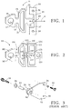
- Fig. 1 is a top perspective view of a safety bracket in accord with the present invention.
- Fig. 2 is a top perspective view of an alternate embodiment of the bracket illustrated in Fig. 1.
- Fig. 3 is a conventional bracket of the prior art.
- Fig. 5 is a perspective view of the apparatus of Fig. 4 after an accident in which the bracket has deformed.
- Figs. 6a and 6b are operational bottom plan views of a table top instrument having a pair of safety brackets in accord with the present invention before and after an accident, respectively.
- a safety bracket 11 of the present invention consists of a steel plate, approximately 2 to 3 millimeters thick having a head section 15 with a central aperture 17 for passage of a screw or bolt therethrough for connection with a table top in a manner illustrated with regard to the prior art plate of Fig. 3.
- the width of the head section at its widest point is about 38 millimeters, while the height of this section is about 29 millimeters.
- the neck 19, being about 9 millimeters wide connects the head section to a shoulder section 21 having relatively thin spaced apart sides 23 and 25, forming a loop, to allow extension between the opposed sides in the axial direction, defined by a longitudinal axis of symmetry, indicated by arrows A.
- the shoulder section is connected to a trunk 27 and then to a torso section 29 which cantilevers outwardly from the trunk.
- the trunk and head have about the same width, while the shoulders and torso are significantly wider, the torso extending slightly beyond the maximum width of the shoulder section.
- the torso section includes opposed holes 31 and 33 for mounting the torso section to an instrument such as a centrifuge.
- the torso section has cantilever or outwardly directed leg spans 35 and 37 of reduced width, about 5 millimeters, for allowing bending of the bracket about a point 39 on the axis of symmetry or other points near the axis of symmetry. Bending of leg members 35 and 37 dissipates twisting forces until the elastic limit of the members is overcome and the members permanently deform. At the same time, a portion of the bracket extends, storing a component of energy.
- a plate or bracket 111 is seen which is similar in shape to the bracket of Fig. 1.
- Plate 111 is characterized by a wide base edge 113 which is the portion of the plate which is mounted to a vibrating or twisting instrument to be supported.
- the perimeter of the plate has undulations 114 and 116 ending in a narrow head section 115 with a central aperture 117 forming a means for mounting to a support surface in conjunction with a screw or similar fastener.
- Undulations 114 and 116 are symmetric about a lengthwise axis, indicated by the line X.
- a safety bracket in accord with the present invention 211 is shown mounted on a table top instrument 213.
- the wider portion 215 of the bracket is mounted to the instrument and the head portion is cantilevered outwardly for connection to a support surface such as a table top.
- each bracket will absorb a shock load from the table top instrument, thereby dissipating energy and preventing a significant amount of energy transfer to the table top supporting the instrument.
Landscapes
- Engineering & Computer Science (AREA)
- General Engineering & Computer Science (AREA)
- Mechanical Engineering (AREA)
- Physics & Mathematics (AREA)
- Acoustics & Sound (AREA)
- Aviation & Aerospace Engineering (AREA)
- Vibration Dampers (AREA)
- Centrifugal Separators (AREA)
Claims (12)
- Sicherheitshalter zur stoßdämpfenden Befestigung einer schwingenden oder rotierenden Vorrichtung an einer Tragoberfläche, mit:einer Platte, die einen Kopfabschnitt aufweist, der mit einem Hals verbunden ist, der seinerseits mit einem Schulterabschnitt verbunden ist, der seinerseits mit einem Schaft verbunden ist, der seinerseits mit einem Rumpfabschnitt verbunden ist, wobei der Hals und der Schaft in seitlicher Richtung schmaler als die Kopf-, Schulter- und Rumpfabschnitte sind und dazu dienen, benachbarte Abschnitte in Ausrichtung entlang einer längsverlaufenden Achse miteinander zu verbinden,wobei der Schulterabschnitt eine Schleife ist, die in rückstellbarer Weise in der Längsrichtung komprimierbar ist, während der Rumpfabschnitt in Drehrichtung um einen Punkt auf der längsverlaufenden Achse in einem Ausmaß biegbar ist, bevor eine permanente Verformung auftritt,wobei die Kopf- und Rumpfabschnitte jeweilige Einrichtungen zur Befestigung eines Teils eines schwingenden oder rotierenden Gerätes an der Tragoberfläche in einer parallelen Beziehung aufweisen.
- Halter nach Anspruch 1, bei dem der Rumpfabschnitt zwei Schenkel aufweist, die sich in entgegengesetzten Richtungen von der in Längsrichtung verlaufenden Achse aus nach außen erstrecken.
- Kalter nach Anspruch 1 oder 2, bei dem der Rumpfabschnitt eine zweite Schleife umfaßt, die in der Längsrichtung ausdehnbar ist.
- Kalter nach Anspruch 1, 2 und 3, bei dem der Halter um die sich in Längsrichtung erstreckende Achse symmetrisch ist.
- Halter nach einem der vorhergehenden Ansprüche, dadurch gekennzeichnet, daß der Kopfabschnitt eine abgestumpfte dreieckförmige Form aufweist.
- Halter nach einem der vorhergehenden Ansprüche, bei dem der Hals und der Schaft gleiche Breiten aufweisen.
- Halter nach Anspruch 2 oder einem der Ansprüche 3 - 6, unter Rückbeziehung auf Anspruch 2, bei dem die Befestigungseinrichtungen eine in dem Kopfabschnitt ausgebildete Öffnung und zwei mit Abstand voneinander angeordneten Öffnungen umfaßt, die in den entgegengesetzt gerichteten Schenkeln ausgebildet sind.
- Halter nach einem der vorhergehenden Ansprüche, bei dem die Befestigungseinrichtung eine erste Öffnung, die in dem Kopfabschnitt ausgebildet ist, und eine zweite Öffnung entlang der längsverlaufenden Achse am entfernten Ende zur ersten Öffnung umfaßt.
- Halter nach einem der vorhergehenden Ansprüche, bei dem die Schleifen aus Plattenmaterial um die längsverlaufende Achse symmetrisch ist/sind.
- Sicherheitshaltersystem für die stoßdämpfende Befestigung einer Zentrifuge an einer Tragoberfläche, wobei das System folgende Teile umfaßt:eine Zentrifuge mit einer Zugangstür an einen Rotoraufnahme-Hohlraum, wobei die Tür durch einen Riegel gesichert ist, der eine vorgegebene maximal zulässige Stoßbelastung vor einer Öffnung aufweist,eine Platte mit einer Basiskante, die mit Abstand von einem Kopfabschnitt entlang einer längsverlaufenden Achse angeordnet ist, wobei die Basiskante Einrichtungen zur Befestigung an einer Seite der Zentrifuge aufweist, während der Kopfabschnitt Einrichtungen zur Befestigung an einer Tragoberfläche aufweist, und mit einem in Drehrichtung verformbaren Plattenabschnitt mit einem Drehmittelpunkt entlang der längsverlaufenden Achse, undeinen ausgeschnittenen Plattenbereich zwischen der Basiskante und dem Kopfabschnitt, der eine Öffnung mit seitlichen Endteilen auf gegenüberliegenden Seiten der sich in Längsrichtung erstreckenden Achse aufweist, wobei die Endteile durch sich seitlich erstreckende, schmale Ränder aus Plattenmaterial umgrenzt sind, und die Ränder eine axiale Steifigkeit entlang der längsverlaufenden Achse derart aufweisen, daß eine permanente Verformung der Plattenränder während eines Rotorausfalls die auf die Zentrifuge unter Einschluß des Türriegels übertragene Stoßbelastung auf einen Wert verringert, der kleiner als die maximal zulässige Stoßbelastung ist.
- Sicherheitshaltersystem nach Anspruch 10, bei dem die Plattenstruktur eine axiale Steifigkeit von ungefähr 2.000 lb pro Zoll bis ungefähr 50.000 lb pro Zoll aufweist.
- Sicherheitssystem nach Anspruch 10, bei dem die Plattenstruktur eine axiale Steifigkeit von ungefähr 5.000 lb pro Zoll bis ungefähr 20.000 lb pro Zoll aufweist.
Applications Claiming Priority (2)
| Application Number | Priority Date | Filing Date | Title |
|---|---|---|---|
| US154618 | 1993-11-17 | ||
| US08/154,618 US5489081A (en) | 1993-11-17 | 1993-11-17 | Safety bracket for table top mounting of a centrifuge |
Publications (2)
| Publication Number | Publication Date |
|---|---|
| EP0653245A1 EP0653245A1 (de) | 1995-05-17 |
| EP0653245B1 true EP0653245B1 (de) | 1997-07-16 |
Family
ID=22552054
Family Applications (1)
| Application Number | Title | Priority Date | Filing Date |
|---|---|---|---|
| EP94307576A Expired - Lifetime EP0653245B1 (de) | 1993-11-17 | 1994-10-14 | Sicherheitshalter für die Befestigung einer Zentrifuge auf einer Tischplatte |
Country Status (3)
| Country | Link |
|---|---|
| US (1) | US5489081A (de) |
| EP (1) | EP0653245B1 (de) |
| DE (1) | DE69404261T2 (de) |
Families Citing this family (8)
| Publication number | Priority date | Publication date | Assignee | Title |
|---|---|---|---|---|
| IT235629Y1 (it) * | 1995-05-19 | 2000-07-12 | Vado Giovanni Antonio | Apparecchio di dimensioni contenute per la separazione centrifuga. |
| US20060130962A1 (en) * | 1998-03-16 | 2006-06-22 | Harrison Wayne J | Containers |
| USD559659S1 (en) * | 2006-10-09 | 2008-01-15 | Greystone Logistics, Inc. | Grommet for a pallet |
| NZ568698A (en) | 2008-05-27 | 2010-12-24 | Corcel Ip Ltd | Method and machine for forming single face corrugated board |
| NZ569425A (en) * | 2008-06-25 | 2011-02-25 | Corcel Ip Ltd | Improvements in corrugating rollers |
| ES2432857T3 (es) * | 2010-12-20 | 2013-12-05 | Bhs Corrugated Maschinen- Und Anlagenbau Gmbh | Rodillo ondulador para la fabricación de cartón ondulado |
| USD739219S1 (en) * | 2014-03-05 | 2015-09-22 | Mark Joshua Mahoney | Wire joiner |
| DE102015202192A1 (de) | 2015-02-06 | 2016-08-11 | Andreas Hettich Gmbh & Co. Kg | Gehäuse einer Zentrifuge |
Family Cites Families (12)
| Publication number | Priority date | Publication date | Assignee | Title |
|---|---|---|---|---|
| US1086442A (en) * | 1912-07-01 | 1914-02-10 | Louis A Cornelius | Pipe-hanger. |
| US2882748A (en) * | 1955-06-23 | 1959-04-21 | Ite Circuit Breaker Ltd | Connecting link for vibrating bodies |
| US3065941A (en) * | 1959-09-21 | 1962-11-27 | Henrite Products Corp | Motor mounting ring |
| FR1507306A (fr) * | 1966-11-17 | 1967-12-29 | Sud Aviation | Dispositif de liaison filtrant les vibrations entre un organe vibrant et un support,notamment un rotor et une structure d'hélicoptère |
| US3506226A (en) * | 1968-06-25 | 1970-04-14 | Minnesota Mining & Mfg | Vibration isolating motor bracket |
| FR2319839A1 (fr) * | 1975-07-28 | 1977-02-25 | Labo Cent Telecommunicat | Element de suspension |
| US4079882A (en) * | 1977-03-18 | 1978-03-21 | Kabushiki Kaisha Kubota Seisakusho | Vibration-isolating apparatus for a centrifuge |
| US4282566A (en) * | 1979-04-16 | 1981-08-04 | The Grote Manufacturing Company, Inc. | Shock mounting bracket for lamp bulb |
| US4492357A (en) * | 1982-12-10 | 1985-01-08 | Morrill Motors Of Virginia, Inc. | Flexible conduit connection for motor |
| DE3416453C1 (de) * | 1984-05-04 | 1991-02-28 | Uranit Gmbh | Rezipient fuer eine Gaszentrifuge |
| DE9011879U1 (de) * | 1990-08-16 | 1990-10-18 | A. Raymond KG, 7850 Lörrach | Schwingungsdämpfendes Befestigungselement für Rohrleitungen |
| US5205374A (en) * | 1991-06-13 | 1993-04-27 | Dana Corporation | Synthetic engine mount strut |
-
1993
- 1993-11-17 US US08/154,618 patent/US5489081A/en not_active Expired - Fee Related
-
1994
- 1994-10-14 DE DE69404261T patent/DE69404261T2/de not_active Expired - Fee Related
- 1994-10-14 EP EP94307576A patent/EP0653245B1/de not_active Expired - Lifetime
Also Published As
| Publication number | Publication date |
|---|---|
| EP0653245A1 (de) | 1995-05-17 |
| US5489081A (en) | 1996-02-06 |
| DE69404261T2 (de) | 1997-11-06 |
| DE69404261D1 (de) | 1997-08-21 |
Similar Documents
| Publication | Publication Date | Title |
|---|---|---|
| DE69804548T2 (de) | Computergehäuse | |
| US4683520A (en) | Mechanical shock mount system for electrical apparatus | |
| US4632198A (en) | Multi-range load cell weighing instrument | |
| US6672732B1 (en) | Micromechanical oscillating device | |
| US5489081A (en) | Safety bracket for table top mounting of a centrifuge | |
| EP1456477B1 (de) | Aufpralldämpfungsrahmen für fernstrassen | |
| CA2051636A1 (en) | Combination beam seat support | |
| US4386390A (en) | Vibration adjustable spacer | |
| KR102427497B1 (ko) | 수배전반용 내진 장치 | |
| KR880000815B1 (ko) | 완충 마운팅 장치 | |
| EP0376729A2 (de) | Schwingungsgedämpfte Struktur | |
| US3949878A (en) | Apparatus for protectively mounting an object | |
| WO1997011288A1 (en) | Vibration isolation device with a dynamic damper | |
| US4955441A (en) | Load cell mounting for rotational control | |
| US4487300A (en) | Vibration adjustable spacer | |
| KR102495504B1 (ko) | 캔틸레버형 면외비틀림 좌굴방지 제진장치 | |
| CN112709780B (zh) | 一种带有铰链式无角位移机构的新型隔振器 | |
| JPH10259840A (ja) | 摩擦ダンパー | |
| US5779194A (en) | Joint for a cantilever arm on a satellite | |
| US20070052143A1 (en) | Vibration isolation device | |
| JP2001003316A (ja) | 落橋防止用緩衝具 | |
| CN222388665U (zh) | 一种用于针剂纸箱的防磕碰装置 | |
| JPH11247935A (ja) | ワイヤマウント及びこれを利用した支持構造 | |
| CN114245629B (zh) | 伺服驱动器的防震装置 | |
| RU1818282C (ru) | Устройство дл фиксации навесных конструкций спутника |
Legal Events
| Date | Code | Title | Description |
|---|---|---|---|
| PUAI | Public reference made under article 153(3) epc to a published international application that has entered the european phase |
Free format text: ORIGINAL CODE: 0009012 |
|
| AK | Designated contracting states |
Kind code of ref document: A1 Designated state(s): DE FR GB IT |
|
| 17P | Request for examination filed |
Effective date: 19950501 |
|
| 17Q | First examination report despatched |
Effective date: 19960619 |
|
| GRAG | Despatch of communication of intention to grant |
Free format text: ORIGINAL CODE: EPIDOS AGRA |
|
| GRAH | Despatch of communication of intention to grant a patent |
Free format text: ORIGINAL CODE: EPIDOS IGRA |
|
| GRAH | Despatch of communication of intention to grant a patent |
Free format text: ORIGINAL CODE: EPIDOS IGRA |
|
| GRAA | (expected) grant |
Free format text: ORIGINAL CODE: 0009210 |
|
| AK | Designated contracting states |
Kind code of ref document: B1 Designated state(s): DE FR GB IT |
|
| REF | Corresponds to: |
Ref document number: 69404261 Country of ref document: DE Date of ref document: 19970821 |
|
| ET | Fr: translation filed | ||
| PLBE | No opposition filed within time limit |
Free format text: ORIGINAL CODE: 0009261 |
|
| STAA | Information on the status of an ep patent application or granted ep patent |
Free format text: STATUS: NO OPPOSITION FILED WITHIN TIME LIMIT |
|
| 26N | No opposition filed | ||
| PGFP | Annual fee paid to national office [announced via postgrant information from national office to epo] |
Ref country code: GB Payment date: 19981001 Year of fee payment: 5 |
|
| PGFP | Annual fee paid to national office [announced via postgrant information from national office to epo] |
Ref country code: FR Payment date: 19981006 Year of fee payment: 5 |
|
| PGFP | Annual fee paid to national office [announced via postgrant information from national office to epo] |
Ref country code: DE Payment date: 19981028 Year of fee payment: 5 |
|
| PG25 | Lapsed in a contracting state [announced via postgrant information from national office to epo] |
Ref country code: GB Free format text: LAPSE BECAUSE OF NON-PAYMENT OF DUE FEES Effective date: 19991014 |
|
| GBPC | Gb: european patent ceased through non-payment of renewal fee |
Effective date: 19991014 |
|
| PG25 | Lapsed in a contracting state [announced via postgrant information from national office to epo] |
Ref country code: FR Free format text: LAPSE BECAUSE OF NON-PAYMENT OF DUE FEES Effective date: 20000630 |
|
| PG25 | Lapsed in a contracting state [announced via postgrant information from national office to epo] |
Ref country code: DE Free format text: LAPSE BECAUSE OF NON-PAYMENT OF DUE FEES Effective date: 20000801 |
|
| REG | Reference to a national code |
Ref country code: FR Ref legal event code: ST |
|
| PG25 | Lapsed in a contracting state [announced via postgrant information from national office to epo] |
Ref country code: IT Free format text: LAPSE BECAUSE OF NON-PAYMENT OF DUE FEES;WARNING: LAPSES OF ITALIAN PATENTS WITH EFFECTIVE DATE BEFORE 2007 MAY HAVE OCCURRED AT ANY TIME BEFORE 2007. THE CORRECT EFFECTIVE DATE MAY BE DIFFERENT FROM THE ONE RECORDED. Effective date: 20051014 |