EP0653174A2 - Upholstery element having a plurality of spring elements placed in regular patterns - Google Patents
Upholstery element having a plurality of spring elements placed in regular patterns Download PDFInfo
- Publication number
- EP0653174A2 EP0653174A2 EP94117486A EP94117486A EP0653174A2 EP 0653174 A2 EP0653174 A2 EP 0653174A2 EP 94117486 A EP94117486 A EP 94117486A EP 94117486 A EP94117486 A EP 94117486A EP 0653174 A2 EP0653174 A2 EP 0653174A2
- Authority
- EP
- European Patent Office
- Prior art keywords
- spring
- spring body
- support
- support plate
- element according
- Prior art date
- Legal status (The legal status is an assumption and is not a legal conclusion. Google has not performed a legal analysis and makes no representation as to the accuracy of the status listed.)
- Granted
Links
Images


Classifications
-
- A—HUMAN NECESSITIES
- A47—FURNITURE; DOMESTIC ARTICLES OR APPLIANCES; COFFEE MILLS; SPICE MILLS; SUCTION CLEANERS IN GENERAL
- A47C—CHAIRS; SOFAS; BEDS
- A47C23/00—Spring mattresses with rigid frame or forming part of the bedstead, e.g. box springs; Divan bases; Slatted bed bases
- A47C23/06—Spring mattresses with rigid frame or forming part of the bedstead, e.g. box springs; Divan bases; Slatted bed bases using wooden springs, e.g. of slat type ; Slatted bed bases
-
- A—HUMAN NECESSITIES
- A47—FURNITURE; DOMESTIC ARTICLES OR APPLIANCES; COFFEE MILLS; SPICE MILLS; SUCTION CLEANERS IN GENERAL
- A47C—CHAIRS; SOFAS; BEDS
- A47C23/00—Spring mattresses with rigid frame or forming part of the bedstead, e.g. box springs; Divan bases; Slatted bed bases
- A47C23/002—Spring mattresses with rigid frame or forming part of the bedstead, e.g. box springs; Divan bases; Slatted bed bases with separate resilient support elements, e.g. elastomeric springs arranged in a two-dimensional matrix pattern
-
- F—MECHANICAL ENGINEERING; LIGHTING; HEATING; WEAPONS; BLASTING
- F16—ENGINEERING ELEMENTS AND UNITS; GENERAL MEASURES FOR PRODUCING AND MAINTAINING EFFECTIVE FUNCTIONING OF MACHINES OR INSTALLATIONS; THERMAL INSULATION IN GENERAL
- F16F—SPRINGS; SHOCK-ABSORBERS; MEANS FOR DAMPING VIBRATION
- F16F1/00—Springs
- F16F1/36—Springs made of rubber or other material having high internal friction, e.g. thermoplastic elastomers
- F16F1/373—Springs made of rubber or other material having high internal friction, e.g. thermoplastic elastomers characterised by having a particular shape
-
- F—MECHANICAL ENGINEERING; LIGHTING; HEATING; WEAPONS; BLASTING
- F16—ENGINEERING ELEMENTS AND UNITS; GENERAL MEASURES FOR PRODUCING AND MAINTAINING EFFECTIVE FUNCTIONING OF MACHINES OR INSTALLATIONS; THERMAL INSULATION IN GENERAL
- F16F—SPRINGS; SHOCK-ABSORBERS; MEANS FOR DAMPING VIBRATION
- F16F3/00—Spring units consisting of several springs, e.g. for obtaining a desired spring characteristic
- F16F3/08—Spring units consisting of several springs, e.g. for obtaining a desired spring characteristic with springs made of a material having high internal friction, e.g. rubber
- F16F3/087—Units comprising several springs made of plastics or the like material
- F16F3/0873—Units comprising several springs made of plastics or the like material of the same material or the material not being specified
Definitions
- the invention relates to an upholstery element, in particular for seating or lying surfaces, with a plurality of spring elements arranged in regular patterns, each with a spring body, arranged between a foot supported on a base and a head with a support plate for an upholstery that can be applied in the form of a support, whereby apart from edge and corner spring elements, the support plates cover the cushion element almost completely over their entire area.
- Steel springs are often used for the upholstery, which, arranged in regular patterns as a spring core between the upholstery layers, absorb the forces that occur when sitting or lying down and adjust allow the pad to the body shape, the padded pad is deformed so that it adapts to the body shape according to the force distribution given by the position. It is also known to store the more or less elastic underlay on slats, which in turn are supported in flexible brackets arranged on both sides, and which are designed either as rigid solid slats or as flexible laminated wood slats. This ensures the desired and required flexibility and adaptability.
- the spring elements are provided as a hollow body between the base and the head, a hollow profile section with a spring body in a plane lying parallel to the support plate and at right angles to the direction of the force loading the spring element, the spring elements designed as plastic parts being arranged in rows and columns on the pad are set.
- This design ensures that a flexibility is achieved which is given by the dissolution of the upholstered seat / lying surface in individual areas, these individual areas being given by the size of the support plates.
- the spring elements attached to the base cover the support surface for the mattress or the like. almost all over, whereby these are arranged in columns and rows.
- These spring elements are attached to a base, and a base extending over the entire lying surface can be provided as the base. Because of the spring action of the individual spring elements, the flexibility of the plate is not important; a rigid plate can therefore also be used.
- each row there is a slat arranged in a frame, on which the foot plates of the spring elements are fastened at preferably equal distances from one another.
- the frame provides a cushion insert that is easy to handle.
- the number of slats is determined by the frame size and the slat spacing specified by the support plate.
- the slats are advantageous or the like on the longitudinal spars of the frame. attached by means of slat hangers, which cooperate with slat heads plugged onto the ends of the slats, the slat hangers and / or the slat head attachments being designed as preferably injection-molded plastic parts.
- an upholstery element in which the base is formed by slats, on which the spring elements are arranged in columns such that they form the rows of upholstery; because of the spring action of the spring elements, the slats can also be designed as rigid slats.
- the individual spring elements are distributed in a regular pattern over the surface to be upholstered, so that the pressure transmitted when sitting or lying down is transmitted to a plurality of spring elements, so that the shape of the cushion element, which is set under the action of the force of the object exerting this force, for example a sitting or lying human body, can adapt well.
- the spring elements each have a footplate for placing on the base and a support plate for placing a mattress-like support, which, again because of the spring action of the spring elements, does not require its own spring action, for example a simple foam pad is sufficient.
- the frame is advantageously formed by at least two frame parts, adjacent frame parts being pivotally hinged to one another with articulated joints connecting the respective parts of the longitudinal spars, the projection of which corresponds to the height of the spring elements.
- a frame is thus achieved, the head and / or foot part of which can be pivoted out relative to the central part, it being understood that between the central part receiving the pelvic region of the body and the head part a further swing-out chest part and / or the foot part the thigh region and a part associated with the lower leg region, which can be pivoted relative to one another in such a way that mutual hindrance during the movement of the support plates during pivoting is excluded.
- the longitudinal and transverse dimensions of the support plates of the spring elements are at most equal to the longitudinal distance of the rows and the transverse distance of the spring elements within the row. This creates an overlap of the surface to be cushioned, on which a support is placed.
- the distances between the adjacent support plates must be such that when the support plates are tilted with one-sided force, the adjacent support plates cannot be held together and can become jammed by jamming in such a way that the spring action is eliminated.
- the support plate is advantageously provided with a number of openings in the area of the support surface for a mattress-like support.
- Each of the spring elements forming the cushion element has a foot that is attached to the base or the crossbar is provided.
- screw connections or engaging collars can be provided. Which type of fastening is the cheapest depends on the design of the spring element, in particular on the foot training.
- Advantageous fastening means are given in that each foot is provided with plug-in dowels which can be inserted into fastening openings in the base or the slats; this results in a simple plug-in system that enables economical production.
- a fixing groove is provided, into which the foot is inserted in a form-fitting manner, wherein this fixing groove can be designed as a groove which receives the corresponding feet;
- This fixing groove can be formed by angle strips placed on the plate or the slats, so that the fixing groove runs continuously in the push-on direction.
- the groove or angled channels can also run transversely to the slat direction, which results in a simpler installation option.
- the base of the spring body has a slat chamber with a substantially rectangular cross-section as a fastening means, so that each of the spring elements can be pushed onto the slats, a fixing knob cooperating with the slat preferably being provided in the interior of the slat chamber on the wall facing the spring body .
- the spring elements can then be slipped onto the support batten, a thin metal strip being placed on the support batten as an assembly aid, which prevents the spring elements pushed onto the support batten from snapping into place before reaching their final position and thus not (or only with difficulty) can be moved beyond these rest areas not assigned to them.
- the spring element is made in one piece with the foot and head; spring bodies with head and foot are produced in one operation, which enables economical production.
- the spring element is designed in several parts, at least the head of the spring body being able to be fixed to the spring body with clamping receptacles, and at least the spring body being made of plastic. It is essential to the spring body itself, the means of the foot for attaching or attaching the support plate can be made of a different material, such as sheet metal.
- all processes for plastics processing can be used for manufacturing;
- the one-piece manufacture in the vulcanizing process from rubber, in the molded foam process, in particular from polyurethane, in the extrusion process from extrudable plastic are advantageous, the spring element or the spring body being cut to length from the extruded strand.
- the head of the spring body must be set up so that, on the one hand, the support plate is held securely and, on the other hand, good force transmission is ensured. It is necessary in the sense of an economical production that the spring body forms a homogeneous body from the selected elastomer. Under these circumstances, it is advantageous if a two-half head clamp is used, with a support plate and a locking flap, which are connected by a joint, which is advantageously designed in the form of a film hinge, and both of which interact on the side opposite the film hinge have, the support plate inserted into a receptacle under the support plate and the locking tab engages the head of the spring body under the support plate, whereby the spring body and support plate are economically connected with simple means.
- This head clamp can be produced from a rigid plastic by injection molding.
- the receptacle for the support plate is arranged below the support plate as angle strips arranged opposite one another molded that this is carried by the angle strips. End stops are provided to secure the position, which limit the insertion of the support plate into the receptacle. It is also advantageous if recesses are provided under the support plate for the locking elements interacting with the support plate in such a way that the support plate used in the final position can no longer be withdrawn. Since here the support plate has to be pushed over this locking point, it is advisable to provide it with a sliding ramp to make it easier to slide on.
- the means of the support plate are designed as insertion angles with locking catches and end stops, so that the support plate is limited with respect to the insertion path and engages in the end position.
- the support plate advantageously has, on both sides of the central axis, sliding angle, end stop and locking means for fastening the support plate.
- the head of the spring body has a reinforcement which is gripped by the closure plate; it is advantageous if the reinforcement has a guide groove which is open to the inside of the spring body and into which the closure plate of the clip is inserted.
- the foot can also be provided as a separate part in the multi-part production; this is also provided with means that allow it to be fixed on the plate or the crossbar. These means correspond to those with which the support plate is fixed to the head of the spring element.
- the foot is designed so that it can be inserted into an insertion groove or into a guideway formed by insertion angles into which the foot can be inserted in a form-fitting manner.
- the spring body as well as its head and its foot are produced independently of one another, as a result of which greater freedom of choice of materials is achieved. Spring bodies with different spring characteristics can also be kept ready and combined with the heads and feet, which allows gradation of the cushion hardness even within a cushion element.
- the spring body of the spring element can be different Be trained. It is advantageous to design the spring body so that its cross-sectional shape is essentially cylindrical. An essentially cylindrical hollow body is thus specified, the production of which can be designed simply and economically.
- the cross-sectional shape of the spring body can also be essentially a polygonal, preferably that of a hexagonal polygon. The head and foot sections are each straight sides of this polygon; what is carried out for the cylindrical training also applies to this training.
- the cross-sectional shape of the spring body is that of an oval or an ellipsoid, which is cut off at about its small central axis and the tip of which is flattened, the foot part being provided in the area of the cut in the area of the small axis, while the flattened tip forms the head part receiving the carrier plate.
- the spring properties can be adapted to the requirements, the spring body being made from an elastomer, advantageously from a closed-cell elastomer foam.
- These profiles are open hollow chamber profiles with one chamber. Open profiles of this type can be produced in the extrusion process as well as in the injection molding process, both production processes allowing the spring body to be produced very economically from the elastomer. It goes without saying that the elastomer can also be foamed.
- the side walls of the cylindrical or, in its basic form, ellipsoidal spring body have an indentation between the head and foot part, so that its cross section assumes the shape of an "eight" which is open in the middle.
- the degree of this indentation allows the desired suspension characteristic to be set in connection with the material and its elastic constants.
- the central indentation can also be designed as a web-like connection, as a result of which the spring body is given the cross-sectional shape of a real "figure of eight". This training creates a two-chamber hollow profile
- the hollow chamber profile thus has four chambers, of which, for example, the side ones, also provided with inserts made of elastic materials, allow the spring characteristic to be set to desired values.
- each of the spring elements between the head and foot part of its spring body has a pair of simply kinked or corrugated plastic webs, the buckling or corrugation directions are preferably directed towards each other so that both "kinks" are retracted.
- a spring body is created which allows a simple change in its spring characteristics in its behavior, simply by the protrusion of the kink.
- the spring body has at least one inner reinforcing web, the reinforcing web (s) preferably running symmetrically to the level of the load. It is possible for the reinforcement web to cross the central plane. Alternatively, it is possible that the reinforcing web is guided on both sides of the median plane from the opposite sides of the spring body to its foot. It is advantageous if the web can be used, the spring body having a chamber at the points where the reinforcement webs start, into which the hammer-like ends of the reinforcement webs are inserted, it being understood that these chambers are formed by external reinforcements.
- the spring body is provided with an elastic, inner support body; this inner support body is advantageously interchangeable, so that, with the same spring body, its spring characteristic can be changed simply by exchanging the inner support body.
- This support body can be an inserted body which is designed as a prism or cylinder section; it preferably has the shape of a cylindrical ring which is arranged at right angles to the spring body, it being advantageous if the support body and spring body are arranged in a crossed manner.
- This arrangement also allows the inner support body to be inserted in a simple manner, for example simple insertion angles on the insides of the head and foot parts of the spring bodies or on the foot and head plate of one-piece spring elements allow this insertion.
- thermoplastic materials that are easy to process can also be used.
- the insertable inner support bodies are advantageously formed from a closed-cell polyurethane foam.
- the spring elements which differ in their spring characteristics, can be used next to each other in a cushion element in order to obtain points of weaker and stronger flexibility. Since the spring elements are interchangeable, there is the simple possibility of changing the position of these areas by using harder or softer spring elements, for which purpose the spring elements are advantageously provided with a mark, for example special coloring, by means of which their spring setting is easily recognized can be.
- the support plate itself is advantageously a ribbed plate, preferably made of plastic, which can also be produced by injection molding.
- the ribs can run parallel to the side edges of the support plate or can be "cornered" so that in the first case the respective diagonal areas are continuous, while in the second case this applies to the respective central areas.
- the rigidity of the support plate is determined by the continuous areas, the resilience by the ribbed areas, so that in the first embodiment there is an overall more rigid support plate, and that the second embodiment results in a support plate, the corner regions of which give way to a load.
- These ribs - as well as a number of openings in a non-ribbed support plate - ensure that the support is adequately ventilated. Adequate ventilation is also achieved in the case of non-ribbed support plates in that the support plate has channels which, like ventilation ducts, allow air to get under the support and thus produce the desired effect.
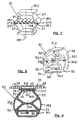
- FIG. 1 shows a simplified, partially cut and broken diagram of a cushion element 1.
- the support for the support 8 is provided in a frame 2 formed from the transverse bars 2.2 (only one of which is shown by breaking off) and longitudinal bars 2.1 arranged opposite one another.
- the longitudinal spars 2.1 (shown here as the side walls of a bed station) are provided with slat receiving strips 2.3, in the slot-like receptacles of which the heads of the slats 5 are arranged at equidistant intervals.
- the slats 5 are provided with holes 5.1, which serve to fix the spring element , the foot or the foot plate of which are provided with plug-in dowels 23.2 (FIGS. 3, 4), 11.1 (FIG.
- the spring elements 30 shown are provided with spring chambers 34 and are pushed onto these slats 5. This gives the spring elements an alignment according to the slat alignment or according to the arrangement of the holes 5.1, which is chosen in the illustration so that all spring elements of a slat 5 are aligned identically, without restricting the invention thereto.
- the support plate 35 shown here rectangular and without ribbing (Fig.
- FIG. 2 shows a multi-part cushion element, the individual parts of which, head part 1.1, back part 1.2, pelvic part 1.3, thigh part 1.4 and lower leg part 1.5 are pivoted against one another.
- the hinges 1.6 are constructed in such a way that the support plates of the spring elements 10 which form the support surface do not engage under pivoting, so that jamming is avoided.
- the known motorized adjustment options can also be used here.
- the arrangement shown here arises when the spring elements 10 are placed on a flat surface; however, it can also arise if the battens of the individual cushion elements that are articulated to one another are arranged, for example, in a longitudinal manner.
- multi-part spring elements 20 are also provided.
- the foot 21.1 and the head 21.2 are designed such that the footplate 23 with the plug-in dowels 23.2 for attachment to the support bar 5 and the support plate 24 for receiving the support can be attached directly .
- FIG. 3 shows a view of a slat 5 equipped with multi-part spring elements with cylindrical spring bodies 20 (illustration broken off).
- the slat 5 is inserted with its slatted head into a slatted head receptacle 7, which in turn is suspended in a slat suspension 6 provided on the longitudinal spar 4, shown here as a frame part; the slatted head is inserted into the cavity of the slatted head receptacle 7, which have recesses on their upper side facing the support plates 24 of the spring elements 20, so that the foot receptacles of spring elements at the edge can be arranged close to the edge.
- the cylindrical spring bodies 20 of the spring elements each have a shaped foot part 21.1 and a shaped head part 21.2, which are diametrically opposite one another.
- the two parts are provided with a base plate 23 with plug-in dowels 23.2 or with a support plate 24, the base plate 23 having slide-on angles 23.1 and the support plate 24 having slide-on angles 24.1 which correspond to the correspondingly shaped base or head part 21.1 or 21.2 of the Interact spring body 20 positively.
- the foot plate 23 and the support plate 24 have means for clamping, which engage behind the foot part 21.1 or the head part 21.2 and thus secure the foot plate or the support plate in the predetermined position; these means are designed as spring tongues 23.3 or 24.3.
- the support plate 24 (or 12, FIG. 5) are arranged diametrically opposite the foot part on the head part of the spring body 20.
- This support plate 24 is designed as an essentially flat support, in the edge regions of which openings 24.1 are provided, which on the one hand exchange air between the air space under the support, mattress or the like. and allows the material of the pad, and on the other hand counteracts slipping of the pad.
- the support plate 35 is provided with ribs, these are advantageously designed as support ribs 38, which are arranged in a ribbed area 37.1 which lies around a central area 36.1 and which are separated by rib-free areas 37.2 are separated.
- the ribs run parallel to the outer edges of the support plate 35, so that the corner regions form the rib-free regions 37.2. Due to the arrangement of the ribs and the formation of the ribs (length, width, depth of the U-shape), they allow the support plates to curve out in such a way that the desired resilience or stiffness is achieved, the resilience being achieved by the tilted and the stiffness determined by the non-tilted areas.
- the one-piece spring element 10 in a side view, in which the spring body is formed by bent webs 13 which are arranged opposite one another in such a way that the directions of the folds 13.1 are directed towards one another, preferably towards one another.
- an inner support body 16 is provided, which can be omitted if the spring bars 13 are suitably designed.
- the one-piece spring element 10 consists of a plate-shaped base 11 and a support plate 12, between which spring bars 13 extend.
- the support plate 12 is flat on the outside, for placing the support.
- the base plate 11 is provided with plug-in plugs 11.1, which allow simple insertion into the holes 5.1 in the slats 5 (FIGS. 1, 2) or in a plate-shaped base.
- the spring bars 13 are integrally formed on the support plate 23 and on the foot plate 22, so that simple and economical manufacture in plastic is made possible, the spring bars 13 being formed symmetrically to one another outwards or inwards. By choosing this shape, the desired or required spring action is achieved together with the choice of the suitable material, with corrugated shapes also being possible; the bridges themselves, whose thickness can be selected, can also widen towards the middle. Together with the choice of material, the spring properties can be determined.
- inner support bodies 16 can be provided which are inserted into clamping receptacles 15 molded onto the base plate 11 or onto the support plate 12.
- FIG. 6 shows a spring body 20 for a multi-part spring element with an essentially cylindrical basic shape, on which foot parts 21.1 and head parts 21.1 are provided for receiving a footplate and a support plate (both not shown in more detail).
- the spring body 20 is provided with inner reinforcing webs 23.1 which attach to its walls 22 and extend in an arc shape to the inner wall of the foot part 21.1 and are arranged symmetrically to the central plane.
- the active force also lies in this central plane; the webs are therefore arranged so that they are evenly acted upon by the force deforming the spring body and stabilize the spring body.
- FIG. 7 shows an embodiment of a polygonal spring body 25 suitable for a multi-part spring element with integrally formed foot and head parts 26.1 and 26.2, which each form receptacles for a footplate and for a support plate.
- the basic shape of this spring body 25 is hexagonal; the spring body 25 consists of the side surfaces 27, which are provided in pairs facing each other in relation to the center plane, the foot part 26.1 and the head part 26.2 closing the polygon.
- the outward angles are overlapped with outer reinforcing webs 27.1, so that the buckling behavior of this spring body 25 can be influenced by the choice of these webs.
- Inner reinforcing webs can also be provided which, as shown in FIG. 6, are arranged symmetrically to the central plane, as shown in FIG.
- tension spring 28 passes through this central plane as a tension spring 28.
- the outer overlapping webs form receiving pockets into which, as shown, internal reinforcement webs 28 with their hammer heads 28.1 can be inserted and anchored, it being self-evident that the side walls 27 in this area of the reinforcement webs the angular edge must be open.
- the internal reinforcement web shown is designed in the illustration as a corrugated tension spring 28; it seems obvious that any other type of tension member can be used. This tension member absorbs the tensile forces occurring between the two free corner edges 16 and stabilizes the spring body, this tension member due to its design, choice of material constants or shape to the desired load conditions can be adjusted.
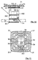
- FIGS. 8 and 9 and 10 show a multi-part spring body 30 for spring elements with an essentially semi-ellipsoidal basic shape, with foot 31.1 and head 31.2, the side walls 32 of which have an indentation 32.1 on both sides.
- these two indentations 32.1 are connected to one another via an inner transverse web 33.1 such that a load in the direction of the main axis of the ellipsoid builds up tensile stress in this transverse web 33.1, which stabilizes the spring body 30 of the spring element.
- the spring body 30 has in the area of its head 31.2 a groove-shaped shape 31.3 for fastening the support plate 35;
- a slat chamber 34 is provided in this embodiment, so that the spring element 35 can be pushed over the slats 5.
- 8 shows the spring body 30 in a schematic perspective and in FIGS. 9 and 10 the spring element with the spring body 30 and the support plate 35 is shown completely in section in a side view (FIG. 9) and in a front view (FIG. 10), the spring body 30 carrying slat (indicated by dashed lines in FIG.
- the term “side view” referring to the open sides of the spring body 30 formed by the hollow profile section, from which the spring action originates.
- the basic form of the spring body 30 of this spring element is a semi-ellipsoid, which is cut off in the region of its short semi-axis to form the foot part 31.1 and is designed as a slat chamber 34, and the tip of which is flat as the head part 31.2.
- the outer wall 32 is advantageously drawn in such that the indentation 32.1 is located approximately in the middle between the foot part 31.1 and the head part 31.2.
- the wall thickness of the outer walls of the spring body 32 can vary over its height, in order to adjust the spring characteristic and to adapt to desired conditions.
- the underside of the spring body 30 is provided with a slat chamber 34, which forms the receptacle for the slat 5 carrying the spring body 30, onto which the spring elements are pushed.
- a fixing knob 34.1 is provided in the slat chamber 34 which engages in a recess (not shown in detail) in the slat 5 and thus fixes the spring body 30 and thus the spring element thereon.
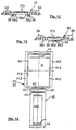
- the head side 31.2 of the spring body 30 is connected to the support plate 35 shown in more detail in FIGS. 11, 12 and 13.
- the head part 31.2, the support plate 35 and the head clamp 40 shown in more detail in FIGS. 14 to 17 are designed such that the support plate 41 and the locking tab 43 of the head clamp 40 encompass the head part 31.2 of the spring body 30, the groove-like recess 31.3 in the head part 31.2 Forms guide groove for the locking tab 43 and receives its corresponding projection 43.1.
- the support plate 35 whose support surface is traversed by ribs 38, has a rib-free area 37 and a central area 37.1 which is also rib-free.
- the ribs 38 are separated from one another by cavities, so that there is sufficient space for the rear ventilation of the support 8 (FIG. 1), which at the same time presses into these cavities, so that an “anchoring" of this support on the support plates 35 occurs counteracts slipping.
- the support plate 41 of the head clamp 40 rests on the guide brackets 36 formed on the support plate 35, on which the head clamp 40 is inserted during assembly, with over-insertion being prevented by end stops 36.1.
- the locking means shown in more detail in FIGS. 14 and 15 are provided on the support plate 35 and consist of a locking lug 36.2 with sliding bevels 36.3, which have the recesses 41.2 in the corresponding side parts of the support plate 41 of the head clamp 40 work together.
- Support plate 41 and locking tab 43 which are pivotally connected to one another via a film hinge, are locked together during assembly by means of locking angles 42 and locking lugs 44, so that both are firmly connected to one another after mounting; thereby engaging in grooves 47 springs 46 ensure that the locking tab in when locking orderly position.
- This simple form is an outflow of the symmetry to the vertical plane which is advantageous for use and divides the spring element in the middle into two mirror-image halves.
- the spring properties can be easily adapted to the requirements by the choice of the material constants and the geometry, the progression of the characteristic curve in particular being able to be influenced by the choice and design of the reinforcements which may be used separately.
- the shape can be such that the wall thickness of the side walls and the receptacles for the head and foot at the edge is (slightly) smaller than in the middle in order to ensure easy removal from the mold when producing in a mold, for example in the case of molded foam.
Landscapes
- Engineering & Computer Science (AREA)
- General Engineering & Computer Science (AREA)
- Mechanical Engineering (AREA)
- Mattresses And Other Support Structures For Chairs And Beds (AREA)
- Golf Clubs (AREA)
- Piezo-Electric Or Mechanical Vibrators, Or Delay Or Filter Circuits (AREA)
- Ultra Sonic Daignosis Equipment (AREA)
- Investigating Or Analyzing Materials By The Use Of Ultrasonic Waves (AREA)
- Springs (AREA)
- Adornments (AREA)
- Electroplating Methods And Accessories (AREA)
Abstract
Description
Die Erfindung betrifft ein Polsterelement insbesondere für Sitz- oder Liegeflächen mit einer Vielzahl von in regelmäßigen Mustern angeordneten Federelementen, jedes mit einem Federkörper, angeordnet zwischen einem auf einer Unterlage abgestützten Fuß und einem Kopf mit einem Auflageteller für eine in Form einer Auflage aufbringbaren Polsterung, wobei die Auflageteller in ihrer Gesamtheit abgesehen von rand- und eckständigen Federelementen das Polsterelement annähernd vollständig flächig überdecken.The invention relates to an upholstery element, in particular for seating or lying surfaces, with a plurality of spring elements arranged in regular patterns, each with a spring body, arranged between a foot supported on a base and a head with a support plate for an upholstery that can be applied in the form of a support, whereby apart from edge and corner spring elements, the support plates cover the cushion element almost completely over their entire area.
Zur Polsterung werden oft Stahlfedern eingesetzt, die, in regelmäßigen Mustern als Federkern zwischen den Polsterlagen angeordnet, die beim Sitzen bzw. Liegen auftretenden Kräfte aufnehmen und ein Anpassen der Unterlage an die Körperform ermöglichen, wobei die gepolsterte Unterlage so verformt wird, daß sie sich an die Körperform entsprechend der durch die Lage gegebenen Kraftverteilung anpaßt. Es ist weiter bekannt, die in sich mehr oder weniger elastische Unterlage auf Latten zu lagern, die ihrerseits in beidseits angeordneten, nachgebenden Halterungen gelagert sind, und die entweder als starre Massiv-Latten oder als nachgebende Schichtholzlatten ausgebildet sind. Dadurch wird die gewünschte und erforderliche Nachgiebigkeit und Anpassungsfähigkeit gewährleistet. Da die Stahlfedern in den so gestützten Polstereinheiten im Laufe der Zeit Geräusche abgeben, und da die Stahlfedern brechen können, wobei dann die frei gewordenen Enden mit ihren Spitzen durch die Abdeckungen dringen können und so ein ruhiges Liegen stören, wurde bereits versucht, die Stahlfedern einzeln in Stoffhüllen einzunähen. Jedoch werden die Metalle der Federn durch die unvermeidbare Feuchtigkeit angegriffen, ein Umstand der über Korrosionen zum Federbruch führen kann.Steel springs are often used for the upholstery, which, arranged in regular patterns as a spring core between the upholstery layers, absorb the forces that occur when sitting or lying down and adjust allow the pad to the body shape, the padded pad is deformed so that it adapts to the body shape according to the force distribution given by the position. It is also known to store the more or less elastic underlay on slats, which in turn are supported in flexible brackets arranged on both sides, and which are designed either as rigid solid slats or as flexible laminated wood slats. This ensures the desired and required flexibility and adaptability. Since the steel springs in the upholstered units supported in this way emit noise over time, and since the steel springs can break, and the ends that have become free can then penetrate through the covers with their tips and thus disturb a quiet lying, the steel springs have already been tried individually sewn into fabric sleeves. However, the metals of the springs are attacked by the inevitable moisture, a fact that can lead to spring breakage due to corrosion.
Bei Lattenrosten als Unterlagen kann durch Verwendung elastischer Puffer als Halteelemente zum beidseitigen Stützen der Starr- oder Federlatten (EU-A-0 031 132) die Korrosionsgefahr ausgeschlossen und eine Geräuschentwicklung weitgehend unterdrückt werden, auch kann durch besondere Ausbildung der Querlatten die zu einer bestimmten Verformung jeder Latte notwendige Kraft eingestellt werden, jedoch lassen sich über die Breite der Latte hinweg keine Abstufungen erreichen, zumal auch hier eine Beeinflussung durch vorhandene Feuchtigkeit nicht auszuschließen ist. Um auch eine Abstufung der abzufangenden Kraft über die Breite der Latte hinweg zu erreichen, wurde bereits vorgeschlagen (EP-A- 0 401 712), die gesamte Fläche der Unterlage mit elastischen Elementen zu belegen, die zur Vermeidung von Überlastungen und zur Begrenzung des verfügbaren Federweges in U-Profilen gelagert sind. Bei dieser Flächenlagerung für Liege- oder Sitzmöbel, etwa für Betten o. dgl. ist die Auflagefläche für eine Polsterauflage wie eine Matratze -wie aus DE 36 12 603 A1 bereits bekannt- in Teilflächen aufgelöst, die in regelmäßigem Muster angeordnet sind, und von denen jedes einzelne dieser Federelemente federnd ausgebildet ist. Dabei werden die Federelemente auf trogförmige Traglatten mit U-förmigem Querschnitt aufgebracht, die parallel zu den Längsholmen des Rahmens verlaufen. Diese weisen entsprechende Halterungen auf, so daß die Federelemente in ihrer Position fixiert werden können. Das freie Ende dieser Federelemente, der Kopf, ist mit einem Auflageteller versehen, der an diesem Kopf festgelegt und so mit diesem verbunden ist, wobei bei Belastung der Weg des Auflagetellers durch die hochstehenden Flansche der U-Profile zur Schonung der Federelemente begrenzt ist. Durch diese Wegbegrenzung wird verhindert, daß sich die Liegefläche der Form des liegenden Körpers eines Menschen anpaßt. Sowohl das Aufbringen der Federelemente auf den Traglatten als auch das Versehen der Federelemente mit den Auflagetellern sind dabei aufwendige Arbeitsgänge, die manuell durchzuführen sind, und deren Kosten die Herstellung einer derartigen Unterlage wirtschaftlich belasten.In the case of slatted frames as underlay, the use of elastic buffers as holding elements for supporting the rigid or spring slats on both sides (EU-A-0 031 132) eliminates the risk of corrosion and largely suppresses noise, and special training of the cross slats can also lead to a certain deformation the necessary force can be set for each slat, but no gradations can be achieved across the width of the slat, especially since an influence by existing moisture cannot be ruled out here either. In order to achieve a gradation of the force to be intercepted across the width of the slat, it has already been proposed (EP-A-0 401 712) to cover the entire surface of the underlay with elastic elements which prevent overloading and limit the available Travel are stored in U-profiles. In this surface storage for reclining or seating furniture, for example for beds or the like, the support surface for an upholstered support such as a mattress - as already known from DE 36 12 603 A1 - is broken down into partial surfaces which are arranged in a regular pattern, and of which each of these spring elements is resilient. The spring elements are applied to trough-shaped battens with a U-shaped cross-section, which are parallel run to the longitudinal spars of the frame. These have corresponding brackets so that the spring elements can be fixed in their position. The free end of these spring elements, the head, is provided with a support plate, which is attached to this head and thus connected to it, the path of the support plate being limited by the upstanding flanges of the U-profiles to protect the spring elements when loaded. This path limitation prevents the lying surface from adapting to the shape of a person's lying body. Both the application of the spring elements to the battens and the provision of the spring elements with the support plates are complex work steps that have to be carried out manually and the costs of which economically burden the manufacture of such a base.
Daraus ergibt sich die der Erfindung zugrunde liegende Aufgabe, nach der ein gattungsgemäßes Polsterelement mit Federung als Unterlage auch für nur wenig elastische matratzenähnliche Auflagen so weitergebildet werden soll, daß das Polsterelement in einfacher Weise aus einfach und reproduzierbar herstellbaren Federelemente mit unterschiedlichen, auch progressiven Federkennlinien, durch die bei den zu erwartenden Lasten auch der Federweg begrenzt ist, so zusammengestellt werden kann, daß bei einfachem Aufbau eine Anpaßbarkeit an unterschiedliche Gegebenheiten möglich ist, wobei äußere Einflüsse, wie Feuchte u. dgl. ausgeschaltet sein sollen, wobei in Weiterführung der Aufgabenstellung insbesondere auch die Federkennlinie veränderbar sein soll.This results in the object on which the invention is based, according to which a generic cushion element with suspension as a base should also be developed for mattresses which are only slightly elastic, so that the cushion element can be produced in a simple manner from spring elements which can be easily and reproducibly produced, with different, also progressive spring characteristics, by which the spring travel is also limited for the loads to be expected, can be put together in such a way that adaptability to different circumstances is possible with a simple structure, external influences such as moisture and. Like. Should be switched off, and in particular the spring characteristic should be changeable in continuation of the task.
Diese Aufgabe wird nach der Erfindung gelöst durch die im Hauptanspruch wiedergegebenen Merkmale; vorteilhafte Weiterbildungen und bevorzugte Ausführungsformen beschreiben die Unteransprüche.This object is achieved according to the invention by the features set out in the main claim; advantageous further developments and preferred embodiments describe the subclaims.
Zur Lösung weisen die Federelemente als zwischen Fuß und Kopf vorgesehene, einem Hohlprofilabschnitt mit einer in einer zur Auflageplatte parallelen Ebene liegenden, rechtwinklig zur Richtung der das Federelement belastenden Kraft ausgerichteten Achse entsprechenden Hohlkörper als Federkörper auf, wobei die als Kunststoffteile ausgebildeten Federelemente in Reihen und Spalten auf der Unterlage festgelegt sind. Durch diese Ausbildung wird erreicht, daß eine Nachgiebigkeit erreicht ist, die von der Auflösung der gepolsterten Sitz-/ Liegefläche in Einzelflächen gegeben ist, wobei diese Einzelflächen durch die Größe der Auflageteller gegeben sind. Die auf der Unterlage befestigten Federelemente überdecken dabei die Auflagefläche für die Matratze o.dgl. nahezu vollflächig, wobei diese in Spalten und Reihen angeordnet sind. Diese Federelemente werden dabei auf einer Unterlage befestigt, wobei als Unterlage eine sich über die gesamte Liegefläche erstreckende Platte vorgesehen sein kann. Wegen der Federwirkung der einzelnen Federelemente kommt es auf eine Nachgiebigkeit der Platte nicht an; es kann daher auch eine starre Platte eingesetzt werden.To solve this, the spring elements are provided as a hollow body between the base and the head, a hollow profile section with a spring body in a plane lying parallel to the support plate and at right angles to the direction of the force loading the spring element, the spring elements designed as plastic parts being arranged in rows and columns on the pad are set. This design ensures that a flexibility is achieved which is given by the dissolution of the upholstered seat / lying surface in individual areas, these individual areas being given by the size of the support plates. The spring elements attached to the base cover the support surface for the mattress or the like. almost all over, whereby these are arranged in columns and rows. These spring elements are attached to a base, and a base extending over the entire lying surface can be provided as the base. Because of the spring action of the individual spring elements, the flexibility of the plate is not important; a rigid plate can therefore also be used.
Da die Federelemente in Reihen angeordnet sind, ist es alternativ dazu vorteilhaft, wenn für jede Reihe eine in einem Rahmen angeordnete Latte vorgesehen ist, auf denen die Fußplatten der Federelemente in vorzugsweise gleichen Abständen voneinander befestigt sind. Durch den Rahmen wird ein Polstereinsatz gewonnen, der gut handhabbar ist. Die Anzahl der Latten ist dabei von Rahmengröße und vom Auflageteller vorgegebenen Lattenabstand bestimmt. Die Latten werden vorteilhaft an den Längsholmen des Rahmens o.dgl. mittels Latten-Aufhänger befestigt, die mit auf die Enden der Latten aufgesteckten Lattenköpfen zusammenwirken, wobei die Latten-Aufhänger und/oder die Lattenkopf-Aufsätze als vorzugsweise gespritzte Kunststoffteile ausgebildet sind. Durch diese Ausbildung wird ein Polsterelement geschaffen, bei dem die Unterlage von Latten gebildet ist, auf denen die Federelemente in Spalten derart angeordnet sind, daß sie die Reihen der Polsterung bilden; dabei können die Latten wegen der Federwirkung der Federelemente auch als Starrlatten ausgebildet sein.As the spring elements are arranged in rows, it is alternatively advantageous if for each row there is a slat arranged in a frame, on which the foot plates of the spring elements are fastened at preferably equal distances from one another. The frame provides a cushion insert that is easy to handle. The number of slats is determined by the frame size and the slat spacing specified by the support plate. The slats are advantageous or the like on the longitudinal spars of the frame. attached by means of slat hangers, which cooperate with slat heads plugged onto the ends of the slats, the slat hangers and / or the slat head attachments being designed as preferably injection-molded plastic parts. Through this design, an upholstery element is created in which the base is formed by slats, on which the spring elements are arranged in columns such that they form the rows of upholstery; because of the spring action of the spring elements, the slats can also be designed as rigid slats.
Mit dieser Ausbildung wird ein Polsterelement erreicht, das nicht korrosionsanfällig ist und bei dem die Geräuschentwicklung unterdrückt wird. Die einzelnen Federelemente sind dabei in einem regelmäßigen Muster über die zu polsternde Fläche verteilt, so daß der beim Sitzen oder beim Liegen übertragene Druck verteilt auf eine Mehrzahl von Federelementen übertragen wird, so daß sich die unter Wirkung der Kraft einstellende Form des Polsterelementes der Form des diese Kraft ausübenden Gegenstandes, beispielsweise ein sitzender oder liegender menschlicher Körper, gut anpassen kann. Dabei weisen die Federelemente je eine Fußplatte zum Aufsetzen auf die Unterlage und einen Auflageteller zum Auflegen einer matratzenähnlichen Auflage auf, die, wiederum wegen der Federwirkung der Federelemente, keiner eigenen Federwirkung bedarf, es genügt beispielsweise eine einfache Schaumauflage.With this design, an upholstery element is achieved which is not susceptible to corrosion and in which the noise is suppressed. The individual spring elements are distributed in a regular pattern over the surface to be upholstered, so that the pressure transmitted when sitting or lying down is transmitted to a plurality of spring elements, so that the shape of the cushion element, which is set under the action of the force of the object exerting this force, for example a sitting or lying human body, can adapt well. The spring elements each have a footplate for placing on the base and a support plate for placing a mattress-like support, which, again because of the spring action of the spring elements, does not require its own spring action, for example a simple foam pad is sufficient.
Vorteilhaft wird dabei der Rahmen von mindestens zwei Rahmenteilen gebildet, wobei aneinander grenzende Rahmenteile mit die jeweiligen Teile der Längsholme ausladend verbindenden Gelenken schwenkbar aneinander angelenkt sind, deren Ausladung der Höhe der Federelemente entspricht. So wird ein Rahmen erreicht, dessen Kopf- und/oder Fußteil gegenüber dem Mittelteil ausfgeschwenkt werden können, wobei es sich von selbst versteht, daß zwischen dem den Beckenbereich des Körpers aufnehmenden Mittelteil und dem Kopfteil ein weiteres ausschwenkbares Brustteil und/oder daß das Fußteil ein dem Oberschenkelbereich und ein dem Unterschenkelbereich zugeordnetes Teil aufweist, die gegeneinander so verschwenkbar sind, daß ein gegenseitiges Behindern bei der Bewegung der Auflageteller beim Verschwenken ausgeschlossen ist.The frame is advantageously formed by at least two frame parts, adjacent frame parts being pivotally hinged to one another with articulated joints connecting the respective parts of the longitudinal spars, the projection of which corresponds to the height of the spring elements. A frame is thus achieved, the head and / or foot part of which can be pivoted out relative to the central part, it being understood that between the central part receiving the pelvic region of the body and the head part a further swing-out chest part and / or the foot part the thigh region and a part associated with the lower leg region, which can be pivoted relative to one another in such a way that mutual hindrance during the movement of the support plates during pivoting is excluded.
Um eine Auflage aufzunehmen, sind dabei die Längs- und Querabmessungen der Auflageteller der Federelemente, höchstens gleich dem Längsabstand der Reihen und dem Querabstand der Federelemente innerhalb der Reihe. Damit wird eine Überdeckung der abzupolsternden Fläche geschaffen, auf die eine Auflage aufgelegt wird. Dabei müssen die Abstände zwischen den benachbarten Auflageteller so sein, daß beim Kippen der Auflageteller bei einseitig wirkender Kraft benachbarte Auflageteller nicht untereinander fassen und sich durch Verklemmen so festsetzen können, daß die Federwirkung aufgehoben ist. Um eine hinreichende Unterlüftung der Auflage zu erreichen, wird der Auflageteller vorteilhaft mit einer Anzahl von Öffnungen im Bereich der Auflagefläche für eine matratzenähnliche Auflage versehen.To accommodate a support, the longitudinal and transverse dimensions of the support plates of the spring elements are at most equal to the longitudinal distance of the rows and the transverse distance of the spring elements within the row. This creates an overlap of the surface to be cushioned, on which a support is placed. The distances between the adjacent support plates must be such that when the support plates are tilted with one-sided force, the adjacent support plates cannot be held together and can become jammed by jamming in such a way that the spring action is eliminated. In order to achieve adequate ventilation of the support, the support plate is advantageously provided with a number of openings in the area of the support surface for a mattress-like support.
Jedes der das Polsterelement bildenden Federelemente weist dabei einen Fuß auf, der mit Mittel zur Befestigung auf der Unterlage bzw. der Latte versehen ist. Zur Befestigung der Federelemente an der Unterlage oder den Latten können Schraubverbindungen oder hintergreifende Kragen vorgesehen sein. Welche Art der Befestigung die günstigste ist, hängt von der Ausbildung des Federelementes ab, insbesondere von der Fuß-Ausbildung. Vorteilhafte Befestigungsmittel sind dadurch gegeben, daß jeder Fuß mit in Befestigungsöffnungen der Unterlage oder der Latten einführbaren Steckdübeln versehen ist; dadurch wird ein einfaches Stecksystem erreicht, das eine wirtschaftliche Herstellung ermöglicht. Eine andere Möglichkeit besteht darin, daß eine Fixierrinne vorgesehen ist, in die der Fuß formschlüssig eingeschoben wird, wobei diese Fixierrinne als eine Nut ausgebildet sein kann, die die korrespondierenden Füße aufnimmt; Diese Fixierrinne kann dabei von auf die Platte oder die Latten aufgesetzte Winkelleisten gebildet sein, so daß die Fixierrinne in Aufschieberichtung durchgehend verläuft. Insbesondere bei Verwendung von Latten als Träger der Federelemente können die Nuten- oder Winkelrinnen auch quer zur Lattenrichtung verlaufen, wodurch sich eine einfachere Montagemöglichkeit ergibt.Each of the spring elements forming the cushion element has a foot that is attached to the base or the crossbar is provided. To fasten the spring elements to the base or the slats, screw connections or engaging collars can be provided. Which type of fastening is the cheapest depends on the design of the spring element, in particular on the foot training. Advantageous fastening means are given in that each foot is provided with plug-in dowels which can be inserted into fastening openings in the base or the slats; this results in a simple plug-in system that enables economical production. Another possibility is that a fixing groove is provided, into which the foot is inserted in a form-fitting manner, wherein this fixing groove can be designed as a groove which receives the corresponding feet; This fixing groove can be formed by angle strips placed on the plate or the slats, so that the fixing groove runs continuously in the push-on direction. In particular when using slats as a support for the spring elements, the groove or angled channels can also run transversely to the slat direction, which results in a simpler installation option.
Alternativ dazu weist der Fuß der Federkörper als Befestigungsmittel eine Lattenkammer mit im wesentlichen rechteckigem Querschnitt auf, so daß jedes der Federelemente auf die Latten aufgeschoben werden kann, wobei vorzugsweise im Inneren der Lattenkammer auf der dem Federkörper zugewandten Wand eine mit der Latte zusammenwirkende Fixierungsnoppe vorgesehen ist. Damit wird die Möglichkeit geschaffen die einzelnen Latten mit Federelemente vorzubestücken und die gesetzten Federelemente in ihrer Position zu fixieren, wobei es sich von selbst versteht, daß die Latten in der gewünschten Position mit einer die Fixierungsnoppen aufnehmenden Bohrung versehen ist, in die diese Noppen bei Erreichen der richtigen Position einschnappen. Für die Montage lassen sich dann die Federelemente auf die Traglatte aufstecken, wobei ein dünner Blechstreifen als Montagehilfe auf die Traglatte aufgelegt ist, der verhindert, daß die auf die Traglatte aufgeschobenen Federelemente vor Erreichen ihrer endgültigen Position einrasten und so nicht (oder nur mit Schwierigkeiten) über diese ihnen nicht zugeordneten Raststellen hinaus bewegt werden können.As an alternative to this, the base of the spring body has a slat chamber with a substantially rectangular cross-section as a fastening means, so that each of the spring elements can be pushed onto the slats, a fixing knob cooperating with the slat preferably being provided in the interior of the slat chamber on the wall facing the spring body . This creates the possibility to pre-equip the individual slats with spring elements and to fix the set spring elements in their position, whereby it goes without saying that the slats in the desired position are provided with a hole which receives the fixing knobs and into which these knobs are reached when they are reached snap into the right position. For assembly, the spring elements can then be slipped onto the support batten, a thin metal strip being placed on the support batten as an assembly aid, which prevents the spring elements pushed onto the support batten from snapping into place before reaching their final position and thus not (or only with difficulty) can be moved beyond these rest areas not assigned to them.
In einer bevorzugten Ausführungsform ist das Federelemente mit Fuß und Kopf einstückig hergestellt; dabei werden Federkörper mit Kopf und Fuß in einem Arbeitsgang hergestellt, was eine wirtschaftliche Herstellung ermöglicht. In einer anderen, ebenfalls bevorzugten Ausführungform ist das Federelement mehrteilig ausgebildet, wobei zumindest der Kopf des Federkörpers mit Klemmaufnahmen an dem Federkörper festlegbar ist, und wobei zumindest der Federkörper aus Kunststoff hergestellt ist. Dabei kommt es wesentlich auf den Federkörper selbst an, wobei die Mittel des Fußes zur Befestigung oder zur Befestigung des Auflagetellers durchaus aus einem anderen Material, etwa auf Blech geformt sein können. Zum Herstellen können im Grundsatz alle Verfahren zur Kunststoffverarbeitung eingesetzt werden; vorteilhaft sind dabei das einstückige Herstellen im Vulkanisierverfahren aus Kautschuk, im Formschäumverfahren, insbesondere aus Polyurethan, im Extrusionsverfahren aus extrudierbarem Kunststoff, wobei das Federelement bzw. der Federkörper vom extrudierten Strang abgelängt wird.In a preferred embodiment, the spring element is made in one piece with the foot and head; spring bodies with head and foot are produced in one operation, which enables economical production. In another, likewise preferred embodiment, the spring element is designed in several parts, at least the head of the spring body being able to be fixed to the spring body with clamping receptacles, and at least the spring body being made of plastic. It is essential to the spring body itself, the means of the foot for attaching or attaching the support plate can be made of a different material, such as sheet metal. In principle, all processes for plastics processing can be used for manufacturing; The one-piece manufacture in the vulcanizing process from rubber, in the molded foam process, in particular from polyurethane, in the extrusion process from extrudable plastic are advantageous, the spring element or the spring body being cut to length from the extruded strand.
Zum Aufsetzen des Auflagetellers muß der Kopf des Federkörpers so eingerichtet sein, daß zum einen der Auflageteller sicher gehalten und zum anderen eine gute Krafteinleitung sicher gestellt ist. Dabei ist es im Sinne einer wirtschaftlichen Herstellung notwendig, daß der Federkörper einen homogenen Körper aus dem gewählten Elastomer bildet. Unter diesen Umständen ist es vorteilhaft, wenn eine zweihälftig ausgebildete Kopfklammer eingesetzt wird, mit einer Tragplatte und einer Verschlußlasche, die durch ein Gelenk, das vorteilhaft in Form eines Folienscharniers gestaltet ist, verbunden sind, und die beide auf der dem Folienscharnier gegenüberliegenden Seite zusammenwirkende Rastmittel aufweisen, wobei die Tragplatte in eine Aufahme unter die Auflageteller eingesetzt und die Verschlußlasche den Kopf des Federkörpers untergreifend mit der Tragplatte verrastet ist, wodurch Federkörper und Auflageteller mit einfachen Mitteln wirtschaflich verbunden sind. Diese Kopfklammer ist dabei aus einem biegesteifen Kunststoff im Spritzgußverfahren herstellbar.To put on the support plate, the head of the spring body must be set up so that, on the one hand, the support plate is held securely and, on the other hand, good force transmission is ensured. It is necessary in the sense of an economical production that the spring body forms a homogeneous body from the selected elastomer. Under these circumstances, it is advantageous if a two-half head clamp is used, with a support plate and a locking flap, which are connected by a joint, which is advantageously designed in the form of a film hinge, and both of which interact on the side opposite the film hinge have, the support plate inserted into a receptacle under the support plate and the locking tab engages the head of the spring body under the support plate, whereby the spring body and support plate are economically connected with simple means. This head clamp can be produced from a rigid plastic by injection molding.
Vorteilhaft ist dabei die Aufnahme für die Tragplatte als einander gegenüberliegend angeordnete Winkelleisten so unter der Auflageplatte angeformt, daß diese von den Winkelleisten getragen wird. Zur Sicherung der Position sind Endanschläge vorgesehen, die das Einschieben des Auflagetellers in die Aufnahme begrenzen. Vorteilhaft ist weiter, wenn unter dem Auflageteller Ausnehmungen für die mit dem Auflageteller zusammenwirkenden Rastelemente so vorgesehen sind, daß der in endgültiger Position eingesetzte Auflageteller nicht mehr zurückgezogen werden kann. Da hier der Auflageteller über diese Raststelle hinweg geschoben werden muß, empfiehlt es sich, diese mit einer Aufgleitrampe zu versehen, um das Aufschieben zu erleichtern.Advantageously, the receptacle for the support plate is arranged below the support plate as angle strips arranged opposite one another molded that this is carried by the angle strips. End stops are provided to secure the position, which limit the insertion of the support plate into the receptacle. It is also advantageous if recesses are provided under the support plate for the locking elements interacting with the support plate in such a way that the support plate used in the final position can no longer be withdrawn. Since here the support plate has to be pushed over this locking point, it is advisable to provide it with a sliding ramp to make it easier to slide on.
Alternativ sind die Mittel des Auflagetellers als Einschiebewinkel mit Sperraste und Endanschlag ausgebildet, so daß die Tragplatte in Bezug auf den Einschiebeweg begrenzt ist und in Endposition einrastet. Vorteilhaft weist dazu der Auflageteller beidseite der Mittelachse, Schiebewinkel, Endanschlag und Rastmittel zum Befestigen der Tragplatte auf. In einer Weiterbildung weist der Kopf des Federkörpers eine Verstärkung auf, die von der Verschlußplatte untergriffen ist; dabei ist es vorteilhaft, wenn die Verstärkung eine zum Inneren des Federkörpers geöffnete Führungsnut aufweist, in die sich die Verschlußplatte der Klammer einlegt.Alternatively, the means of the support plate are designed as insertion angles with locking catches and end stops, so that the support plate is limited with respect to the insertion path and engages in the end position. For this purpose, the support plate advantageously has, on both sides of the central axis, sliding angle, end stop and locking means for fastening the support plate. In a further development, the head of the spring body has a reinforcement which is gripped by the closure plate; it is advantageous if the reinforcement has a guide groove which is open to the inside of the spring body and into which the closure plate of the clip is inserted.
Auch der Fuß kann bei der mehrteiligen Herstellung als gesondertes Teil vorgesehen werden; dabei ist diese ebenfalls mit Mitteln versehen, die das Festlegen auf der Platte bzw. der Latte erlauben. Diese Mittel entsprechen denen, mit denen der Auflageteller am Kopf des Federelementes festgelegt wird. Insbesondere wird der Fuß so ausgebildet, daß er in eine Einschiebenut oder in eine von Einschiebewinkeln gebildete Führungsbahn eingeführt werden kann, in die der Fuß formschlüssig einsetzbar ist. Bei den mehrteiligen Ausführungsformen werden Federkörper sowie dessen Kopf und dessen Fuß unabhängig voneinander hergestellt, wodurch eine größere Freiheit von der Materialwahl erreicht wird. Auch können Federkörper mit unterschiedlichen Federcharakteristiken bereit gehalten und mit den Köpfen und Füßen kombiniert werden, was eine Abstufung der Polsterhärte auch innerhalb eines Polsterelementes erlaubt.The foot can also be provided as a separate part in the multi-part production; this is also provided with means that allow it to be fixed on the plate or the crossbar. These means correspond to those with which the support plate is fixed to the head of the spring element. In particular, the foot is designed so that it can be inserted into an insertion groove or into a guideway formed by insertion angles into which the foot can be inserted in a form-fitting manner. In the multi-part embodiments, the spring body as well as its head and its foot are produced independently of one another, as a result of which greater freedom of choice of materials is achieved. Spring bodies with different spring characteristics can also be kept ready and combined with the heads and feet, which allows gradation of the cushion hardness even within a cushion element.
Der Federkörper des Federelementes kann dabei in unterschiedlicher Weise ausgebildet sein. Vorteilhaft ist, den Federkörper so zu gestalten, daß dessen Querschnittsform im wesentlichen eine zylindrische ist. Damit wird ein im wesentlichen zylindrischer Hohlkörper vorgegeben, dessen Herstellung einfach und wirtschaftlich gestaltet werden kann. Auch kann die Querschnittsform des Federkörpers im wesentlichen eine polygonale, vorzugsweise die eines sechseckigen Polygons sein. Dabei sind Kopf- und der Fußteil jeweils gerade Seiten dieses Polygons; für diese Ausbildung gilt ebenfalls das, was für die zylindrische Ausbildung ausgeführt ist. Eine weitere Ausbildung ist dadurch gegeben, daß die Querschnittsform des Federkörpers die eines Ovals oder eines Ellipsiods ist, das etwa bei seiner kleinen Mittelachse abgeschnitten und dessen Spitze abgeflacht ist, wobei das Fußteil im Bereich des Schnittes im Bereich der kleinen Achse vorgesehen ist, während die abgeflachte Spitze das den Tragteller aufnehmende Kopfteil bildet. Durch die Abwandlung der Querschnitts-Formen lassen sich die Federeigenschaften den Anforderungen anpassen, wobei der Federkörper aus einem Elastomer, vorteilhaft aus einem geschlossen-zelligem Elastomerschaum hergestellt ist. Diese Profile sind offfene Hohlkammerprofile mit einer Kammer. Offene Profile dieser Art lassen sich im Strangpreßverfahren ebenso herstellen wie im Spritzgußverfahren, wobei beide Herstellungsverfahren eine sehr wirtschaftliche Herstellung des Federköpers aus dem Elastomer erlauben. Daß der Elastomer auch aufgeschäumt sein kann, erscheint dabei selbstverständlich.The spring body of the spring element can be different Be trained. It is advantageous to design the spring body so that its cross-sectional shape is essentially cylindrical. An essentially cylindrical hollow body is thus specified, the production of which can be designed simply and economically. The cross-sectional shape of the spring body can also be essentially a polygonal, preferably that of a hexagonal polygon. The head and foot sections are each straight sides of this polygon; what is carried out for the cylindrical training also applies to this training. Another embodiment is given in that the cross-sectional shape of the spring body is that of an oval or an ellipsoid, which is cut off at about its small central axis and the tip of which is flattened, the foot part being provided in the area of the cut in the area of the small axis, while the flattened tip forms the head part receiving the carrier plate. By modifying the cross-sectional shapes, the spring properties can be adapted to the requirements, the spring body being made from an elastomer, advantageously from a closed-cell elastomer foam. These profiles are open hollow chamber profiles with one chamber. Open profiles of this type can be produced in the extrusion process as well as in the injection molding process, both production processes allowing the spring body to be produced very economically from the elastomer. It goes without saying that the elastomer can also be foamed.
Zur Veränderung der Federeigenschaft weisen die seitlichen Wände des zylindrischen oder des in seiner Grundform ellipsoiden Federkörpers zwischen Kopf- und Fußteil einen Einzug auf, so daß sein Querschnitt die Form einer in der Mitte offenen "Acht" annimmt. Der Grad dieses Einzuges erlaubt, in Verbindung mit dem Material und seinen elastischen Konstanten die gewünschte Federungskennlinie einzustellen. Dabei kann der mittige Einzug auch als stegartige Verbindung ausgebildet sein, wodurch der Federkörper die Querschnittsform einer echten "Acht" erhält. Bei dieser Ausbildung entsteht ein Zweikammer-HohlprofilTo change the spring properties, the side walls of the cylindrical or, in its basic form, ellipsoidal spring body have an indentation between the head and foot part, so that its cross section assumes the shape of an "eight" which is open in the middle. The degree of this indentation allows the desired suspension characteristic to be set in connection with the material and its elastic constants. The central indentation can also be designed as a web-like connection, as a result of which the spring body is given the cross-sectional shape of a real "figure of eight". This training creates a two-chamber hollow profile
Weiter ist es bei dieser Ausbildung vorteilhaft, wenn Seitenverbinder vorgesehen sind, die beidseits die beiden ausladenden Bögen der "Acht" des Federkörpers miteinander verbinden, wobei diese sich zumindest über einen Teil der Länge der "Acht" des Federkörpers erstrecken. Diese Seitenverbinder überbrücken den Einzug, der sich mittig befinden kann; dabei ist die Breite der Seitenverbinder so, daß sie sich zumindest über einen Teil der Breite des Federkörpers erstrecken, wobei die Anordnung der Seitenverbinder vorteilhaft symmetrisch zur Mittelebene des Federkörpers erfolgt. Bei dieser Ausführungsform weist somit das Hohlkammerprofil vier Kammern auf, von denen etwa die seitlichen, auch mit Einsätzen aus elastischen Materialien versehen, die Einstellung der Federcharakteristik auf gewünschte Werte erlaubt.It is also advantageous in this embodiment if side connectors are provided which connect the two protruding arches of the "eight" of the spring body to each other, these extending at least over part of the length of the "eight" of the spring body. These side connectors bridge the feed, which can be in the middle; the width of the side connectors is such that they extend at least over part of the width of the spring body, the arrangement of the side connectors advantageously being symmetrical to the central plane of the spring body. In this embodiment, the hollow chamber profile thus has four chambers, of which, for example, the side ones, also provided with inserts made of elastic materials, allow the spring characteristic to be set to desired values.
Eine andere Ausbildungsform ist dadurch gegeben, daß jedes der Federelemente zwischen Kopf- und Fußteil seines Federkörpers ein Paar einfach geknickter oder gewellter Kunststoffstege aufweist, deren Knick- bzw. Wellrichtungen vorzugsweise so gegeneinander gerichtet sind, daß beide "Knicke" eingezogen sind. Mit dieser Ausbildung wird ein Federkörper geschaffen, der in seinem Verhalten eine einfache Änderung seiner Federcharakteristik erlaubt, allein durch die Ausladung des Knickes.Another form of training is given in that each of the spring elements between the head and foot part of its spring body has a pair of simply kinked or corrugated plastic webs, the buckling or corrugation directions are preferably directed towards each other so that both "kinks" are retracted. With this design, a spring body is created which allows a simple change in its spring characteristics in its behavior, simply by the protrusion of the kink.
Um die Federcharakteristik des Federkörpers den Erfordernissen anpassen zu können, wird weiter vorgeschlagen, daß der Federkörper mindestens einen inneren Verstärkungssteg aufweist, wobei vorzugsweise der/die Verstärkungsstege symmetrisch zur Ebene der belastenden Kraft verlaufen. Dabei ist es möglich, daß der Verstärkungssteg die Mittelebene durchquert. Alternativ ist möglich, daß der Verstärkungssteg beidseits der Mittelebene von den einander gegenüberliegenden Seiten des Federköpers zu dessen Fuß geführt ist. Vorteilhaft ist dabei, wenn der Steg einsetzbar ist, wobei der Federkörper an den Stellen, an denen der/die Verstärkungsstege ansetzen, eine Kammer aufweisen, in die die hammerartig ausgebildeten Enden des/der Verstärkungsstege eingesetzt werden, wobei es sich von selbst versteht, daß diese Kammern von äußeren Verstärkungen gebildet sind.In order to be able to adapt the spring characteristic of the spring body to the requirements, it is further proposed that the spring body has at least one inner reinforcing web, the reinforcing web (s) preferably running symmetrically to the level of the load. It is possible for the reinforcement web to cross the central plane. Alternatively, it is possible that the reinforcing web is guided on both sides of the median plane from the opposite sides of the spring body to its foot. It is advantageous if the web can be used, the spring body having a chamber at the points where the reinforcement webs start, into which the hammer-like ends of the reinforcement webs are inserted, it being understood that these chambers are formed by external reinforcements.
Eine vorteilhafte Alternative dazu ist dadurch gegeben, daß der Federkörper mit einem elastischen, inneren Stützkörper versehen ist; dieser innere Stützkörper ist vorteilhaft austauschbar, so daß bei gleichem Federkörper dessen Federcharakteristik durch bloßes Austauschen des inneren Stützkörpers verändert werden kann. Dieser Stützkörper kann dabei ein eingesetzter Körper sein, der als Prisma- oder Zylinderabschnitt ausgebildet ist; vorzugsweise hat er die Form eines zylindrischen Ringes, der rechtwinklig zu dem Federkörper angeordnet ist, wobei es vorteilhaft ist, wenn Stützkörper und Federkörper gekreuzt angeordnet werden. Diese Anordnung erlaubt auch in einfacher Weise das Einsetzen des inneren Stützkörpers, wobei beispielsweise einfache Einschiebewinkel auf den Innenseiten der Kopfund Fußteile der Federkörper bwz., an Fuß- und Kopfplatte einstükkiger Federelemente dieses Einschieben gestatten. Bei dieser Ausgestaltung der Federelemente bzw. der Federkörper wird erreicht, daß auch leicht zu verarbeitende thermoplastische Kunststoffe eingesetzt werden können. Vorteilhaft werden dabei die einsetzbaren inneren Stützkörper aus einem geschlossen-zelligen Polyurethanschaum gebildet. Die so in ihrer Federcharakteristik unterschiedlichen Federelemente können in einem Polsterelement nebeneinander eingesetzt werden, um Stellen schwächerer und stärkerer Nachgiebigkeit zu erhalten. Da die Federelemente auswechselbar sind, ergibt sich die einfache Möglichkeit auch die Lage dieser Bereiche durch das Einsetzen härterer oder weicherer Federelemente zu ändern, wozu die Federelemente vorteilhaft mit einem Kennzeichen, beispielsweise besondere Einfärbungen, versehen sind, durch das ihre Feder-Einstellung ohne weiteres erkannt werden kann.An advantageous alternative to this is given by the fact that the spring body is provided with an elastic, inner support body; this inner support body is advantageously interchangeable, so that, with the same spring body, its spring characteristic can be changed simply by exchanging the inner support body. This support body can be an inserted body which is designed as a prism or cylinder section; it preferably has the shape of a cylindrical ring which is arranged at right angles to the spring body, it being advantageous if the support body and spring body are arranged in a crossed manner. This arrangement also allows the inner support body to be inserted in a simple manner, for example simple insertion angles on the insides of the head and foot parts of the spring bodies or on the foot and head plate of one-piece spring elements allow this insertion. With this configuration of the spring elements or the spring body, it is achieved that thermoplastic materials that are easy to process can also be used. The insertable inner support bodies are advantageously formed from a closed-cell polyurethane foam. The spring elements, which differ in their spring characteristics, can be used next to each other in a cushion element in order to obtain points of weaker and stronger flexibility. Since the spring elements are interchangeable, there is the simple possibility of changing the position of these areas by using harder or softer spring elements, for which purpose the spring elements are advantageously provided with a mark, for example special coloring, by means of which their spring setting is easily recognized can be.
Der Auflageteller selbst ist vorteilhaft eine verrippt ausgebildete Platte vorzugsweise aus Kunststoff, die ebenfalls im Spritzgußverfahren herstellbar ist. Je nach gewünschter Nachgiebigkeit können die Rippen dabei parallel zu den Seitenkanten des Auflagetellers verlaufen oder "über Eck" geführt sein, so daß im ersten Fall die jeweiligen diagonalen Bereiche durchgehend sind, während dies im zweiten Fall für die jeweiligen Mittenbereiche gilt. Dabei wird die Steifigkeit des Auflagetellters von den durchgehenden Bereichen, die Nachgiebigkeit von den gerippten Bereichen bestimmt, so daß bei der ersten Ausführung ein insgesamt steiferer Auflageteller gegeben ist, und daß die zweite Ausführung einen Auflageteller ergibt, dessen Eckbereiche einer Belastung nachgeben. Durch diese Rippen wird - ebenso wie durch eine Anzahl von Öffnungen in einem nicht verrippten Auflagteteller - erreicht, daß eine hinreichende Unterlüftung der Auflage gegeben ist. Eine hinreichende Unterlüftung wird bei nicht verrippten Auflagetellern auch dadurch erreicht, daß der Auflageteller Rinnen aufweist, die ähnlich Belüftungskanälen Luft unter die Auflage gelangen läßt und so den gewünschten Effekt bewirkt.The support plate itself is advantageously a ribbed plate, preferably made of plastic, which can also be produced by injection molding. Depending on the desired flexibility, the ribs can run parallel to the side edges of the support plate or can be "cornered" so that in the first case the respective diagonal areas are continuous, while in the second case this applies to the respective central areas. The rigidity of the support plate is determined by the continuous areas, the resilience by the ribbed areas, so that in the first embodiment there is an overall more rigid support plate, and that the second embodiment results in a support plate, the corner regions of which give way to a load. These ribs - as well as a number of openings in a non-ribbed support plate - ensure that the support is adequately ventilated. Adequate ventilation is also achieved in the case of non-ribbed support plates in that the support plate has channels which, like ventilation ducts, allow air to get under the support and thus produce the desired effect.
Das Wesen der Erfindung wird an Hand der in den Figuren 1 bis 17 dargestellten Ausführungsbeispiele näher erläutert; dabei zeigen:
- Fig. 01:
- Polsterelement, schematisch, Aufsicht;
- Fig. 02:
- Mehrteiliges, verstellbares Polsterelement, schematische Seitansicht
- Fig. 03:
- Latten-Unterlage, bestückt mit Federelementen;
- Fig. 04:
- Dreiteiliges Federelement mit Fußplatte und Auflageteller, Darstellung mit eingesetztem Stützkörper);
- Fig. 05:
- Federelement mit seitlichen Federstegen und innerem Stützkörper;
- Fig. 06:
- Zylindrisches Federelement mit angeformten Aufnahmen für Auflageteller und Fußeinsatz und mit inneren Verstärkungsstegen, perspektivisches Schema;
- Fig. 07:
- Polygonales (hier: sechseckiges) Federelement mit angeformten Aufnahmen für Auflageteller und Fußeinsatz und mit innenliegendem Verstärkungssteg, ausgebildet als Wellfeder, perspektivisches Schema;
- Fig. 08:
- Federelement mit ellipsoider Grundform mit eingezogenen Seitenteilen, innerem Verstärkungssteg und äußeren Seitenverbindern, perspektivisches Schema;
- Fig. 09:
- Federelement nach Figur 8 mit Tragteller, geschnitten;
- Fig. 10:
- Federelement nach Fig. 9, rechtwinklig zur dortigen Schnittrichtung geschnitten;
- Fig. 11:
- Auflageteller, Aufsicht;
- Fig. 12:
- Auflageteller, Seitansicht in Einschubrichtung der Kopfklammer geschnitten;
- Fig. 13:
- Auflageteller, Seitansicht rechtwinklig zur Einschubrichtung der Kopfklammer geschnitten
- Fig. 14:
- Kopfklammer, geöffnet, Innenansicht;
- Fig. 15:
- Kopfklammer, geöffnet, Seitansicht geschnitten;
- Fig. 16:
- Kopfklammer, geschlossen, Aufsicht, geschnitten;
- Fig. 17:
- Kopfklammer, geschlossen, Seitansicht, geschnitten;
- Fig. 01:
- Upholstery element, schematic, supervision;
- Fig. 02:
- Multi-part, adjustable upholstery element, schematic side view
- Fig. 03:
- Slatted base, equipped with spring elements;
- Fig. 04:
- Three-part spring element with base plate and support plate, illustration with inserted support body);
- Fig. 05:
- Spring element with spring bars on the side and inner support body;
- Fig. 06:
- Cylindrical spring element with molded receptacles for support plates and foot inserts and with internal reinforcement bars, perspective diagram;
- Fig. 07:
- Polygonal (here: hexagonal) spring element with molded receptacles for the support plate and foot insert and with internal reinforcing web, designed as a corrugated spring, perspective diagram;
- Fig. 08:
- Spring element with ellipsoidal basic shape with drawn-in side parts, inner reinforcement web and outer side connectors, perspective diagram;
- Fig. 09:
- Spring element according to Figure 8 with support plate, cut;
- Fig. 10:
- 9, cut at right angles to the direction of cut there;
- Fig. 11:
- Support plate, supervision;
- Fig. 12:
- Support plate, side view cut in the direction of insertion of the head clamp;
- Fig. 13:
- Support plate, side view cut at right angles to the direction of insertion of the head clamp
- Fig. 14:
- Head clamp, opened, inside view;
- Fig. 15:
- Head clamp, opened, side view cut;
- Fig. 16:
- Head clamp, closed, supervision, cut;
- Fig. 17:
- Head clamp, closed, side view, cut;
Die Figur 1 zeigt ein vereinfachtes, teilgeschnittenes und abgebrochenes Schema eines Polsterelementes 1. In einem aus den einander gegenüber liegend angeordneten Querholmen 2.2 (durch Abbruch nur einer dargestellt) und Längsholmen 2.1 gebildeten Rahmen 2 ist das Auflager für die Auflage 8 vorgesehen. Dazu sind an die (hier als Seitenwangen einer Bettstelle dargestellten) Längsholme 2.1 mit Lattenaufnahmeleisten 2.3 versehen, in deren langlochähnliche Aufnahmen die Köpfe der Latten 5 in äquidistanten Abständen angeordneten Latten 5. Die Latten 5 sind mit Bohrungen 5.1 versehen, die zur Festlegung der Federelement dienen, deren Fuß bzw. deren Fußplatte mit Steckdübeln 23.2 (Fig. 3, 4), 11.1 (Fig.5) versehen sind, die in diese Bohrugen 5.1 eingesetzt werden. Die eingezeichneten Federelemente 30 (Einzelheiten s. Fig. 8-10) sind mit Federkammern 34 versehen und werden auf diese Latten 5 aufgeschoben. Dadurch erhalten die Federelemente eine Ausrichtung gemäß Lattenausrichtung oder gemäß Anordnung der Bohrungen 5.1, die in der Darstellung so gewählt ist, daß alle Federelemente einer Latten 5 gleich ausgerichtet sind, ohne die Erfindung darauf zu beschränken. Die Auflageteller 35, hier rechteckig und ohne Verrippung (Fig. 9-11) dargestellt, füllen dabei von schmalen Randstreifen und den Zwischenräumen zwischen den einzelnen Auflagetellern 35 abgesehen, die Fläche des Polsterelementes 1 nahezu vollständig aus und nehmen eine Auflage 8 auf, die wegen der Federeigenschaft des mit diesen Federelementen gebildeten Polsterelementes 1 keiner eigenen Federung mehr bedarf, so daß einfache Auflagen, beispielsweise Schaumstoffmatten, vorgesehen sein können. Es versteht sich dabei von selbst, daß auch übliche Matratzen aufgelegt werden können. Um die Federelemente 30 mit im Winkel zueinander verlaufender Ausrichtung einsetzen zu können, werden der Einfachheit halber quadratische Auflageteller benutzt, wie in Figur 11 näher dargestellt.FIG. 1 shows a simplified, partially cut and broken diagram of a
In der Figur 2 ist ein mehrteiliges Polsterelement stark schematisiert dargestellt, dessen einzelnen Teile, Kopfteil 1.1, Rückenteil 1.2, Beckenteil 1.3, Oberschenkelteil 1.4 und Unterschenkelteil 1.5 gegeneinander verschwenkbar aneinander gelenkt sind. Die Scharniere 1.6 sind dabei so aufgebaut, daß sich die die Auflagefläche bildenden Auflageteller der Federelemente 10 bei einem Verschwenken nicht untergreifen, so daß ein Verklemmen vermieden wird. Dabei ist dabei selbstverständlich, daß hier auch die bekannten motorischen Verstellmöglichkeiten eingesetzt werden können. Die hier dargestellte Anordnung entsteht, wenn die Federelemente 10 auf eine flächige Unterlage aufgesetzt werden; sie kann jedoch auch dann entstehen, wenn die Traglatten der einzelnen aneinander gelenkten Polsterelemente beispielsweise längsverlaufend angeordnet sind.FIG. 2 shows a multi-part cushion element, the individual parts of which, head part 1.1, back part 1.2, pelvic part 1.3, thigh part 1.4 and lower leg part 1.5 are pivoted against one another. The hinges 1.6 are constructed in such a way that the support plates of the
Neben den in Figur 2 angedeuteten einstückigen Federelementen 10 sind auch mehrteilige Federelemente 20 (bzw. 25, 30) vorgesehen. Bei den in der Figur 3 dargestellten dreiteiligen Federelementen mit zylindrischem Federkörper 20 sind der Fuß 21.1 und der Kopf 21.2 so ausgebildet, daß die Fußplatte 23 mit den Steckdübeln 23.2 zum Befestigen auf der Traglatte 5 und der Auflageteller 24 zur Aufnahme der Auflage unmittelbar angesetzt werden können. Die Figur 3 zeigt eine Ansicht einer mit mehrteiligen Federelementen mit zylindrischen Federkörpern 20 bestückten Latte 5 (Darstellung abgebrochen). Die Latte 5 ist mit ihrem Lattenkopf in eine Lattenkopf-Aufnahme 7 eingesetzt, die ihrerseits in eine am Längsholm 4, hier als Rahmenteil dargestellt, vorgesehenen Latten-Aufhängung 6 eingehängt ist; der Lattenkopf ist in den Hohlraum des Lattentkopf-Aufnahme 7 eingeführt, die an ihrer den Tragtellern 24 der Federelemente 20 zugewandten Oberseite Ausnehmungen aufweisen, so daß die Fußaufnahmen randständiger Federelemente nahe am Rand angeordnet werden können. Die zylindrisch ausgebildeten Federkörper 20 der Federelemente weisen je einen ausgeforemten Fußteil 21.1 und einen ausgeformten Kopfteil 21.2 auf, die einander diametral gegenüber liegen. Die beiden Teile sind dabei mit einer Fußplatte 23 mit Steckdübeln 23.2 bzw. mit einem Auflageteller 24 versehen sind, wobei die Fußplatte 23 Aufschiebewinkel 23.1 und der Auflageteller 24 Aufschiebewinkel 24.1 aufweisen, die mit den korrespondierend ausgeformten Fuß- bzw. Kopfteil 21.1 bzw. 21.2 des Federkörpers 20 formschlüssig zusammenwirken. Weiter weisen Fußplatte 23 und Auflageteller 24 Mittel zum Klemmen auf, die jeweils das Fußteil 21.1 bzw. das Kopfteil 21.2 hintergreifen und so die Fußplatte bzw. den Auflageteller in der vorgegebenen Position sichern; diese Mittel sind in der Darstellung als Federzungen 23.3 bzw. 24.3 ausgebildet. Die Auflageteller 24 (bzw. 12, Fig. 5) sind dabei diametral gegenüber dem Fußteil am Kopfteil des Federkörpers 20 angeordnet. Dieser Auflageteller 24 ist als im wesentlichen plane Auflage ausgebildet, in deren Randbereichen Öffnungen 24.1 vorgesehen sind, die zum einen einen Luftaustausch zwischen dem Luftraum unter der Auflage, Matratze o.dgl. und dem Material der Auflage zuläßt, und die zum anderen einem Verrutschen der Auflage entgegenwirkt.In addition to the one-
Wird -wie in den Figuren 11, 12 und 13 näher dargestellt- der Auflageteller 35 mit Rippen versehen, sind diese vorteilhaft als als Tragrippen 38 ausgebildet, die in um einen Zentralbereich 36.1 liegenden, verrippten Bereich 37.1 angeordnet sind, die durch rippenfreie Bereiche 37.2 voneinander getrennt sind. Im dargestellten Beispiel verlaufen die Rippen parallel zu den Außenkanten des Auflagetellers 35, so daß die Eckbereiche die rippenfreien Bereiche 37.2 bilden. Durch die Rippenanordnung und die Rippenausbildung (Länge, Breite, Tiefe der U-Form) lassen sie die Auflageteller derart ausilen, daß gewünschte Nachgiebigkeiten bzw. Steifigkeiten erreicht werden, wobei die Nachgiebigkeit durch die verippten und die Steiigkeit durch die nicht-verippten Bereiche bestimmt werden. Die Figur 5 zeigt ein einstückiges Federelement 10 in Seitansicht, bei dem der Federkörper von geknickten Stegen 13 gebildet ist, die einander gegenüber liegend so angeordnet sind, daß die Richtungen der Einknickungen 13.1 gegeneinander, vorzugsweise aufeinander zu gerichtet sind. In der Darstellung ist ein innerer Stützkörper 16 vorgesehen, der bei geeigneter Auslegung der Federstege 13 entfallen kann. Das einstückige Federelement 10 besteht aus einer plattenförmigen Basis 11 und einem Auflageteller 12, zwischen denen sich Federstege 13 erstrecken. Der Auflageteller 12 ist nach außen hin eben ausgebildet, zum Auflegen der Auflage. Die Fußplatte 11 ist mit Steckdübeln 11.1 versehen, die ein einfaches Einstecken in die Bohrungen 5.1 in den Latten 5 (Fig. 1, 2) oder in die einer plattenförmigen Unterlage erlauben. Die Federstege 13 sind an den Auflageteller 23 und an die Fußplatte 22 angeformt, so daß ein einfaches und wirtschaftliches Herstellen in Kunststoff ermöglicht wird, wobei die Federstege 13 symmetrisch zueinander nach außen oder nach innen ausgeformt sind. Durch Wahl dieser Ausformung wird zusammen mit der Wahl des geeigneten Materials die gewünschte bzw. erforderliche Federwirkung erreicht, wobei auch gewellte Ausformungen möglich sind; die Stege selbst, deren Stärke wählbar ist, können sich auch zur Mitte hin verbreitern. Zusammen mit der Wahl des Materials lassen sich so die Federeigenschaften bestimmen. Um ein sicheres Wiederaufrichten auch nach längerem Gebrauch und auch nach Überlastungen zu erreichen, können innere Stützkörper 16 vorgesehen sein, die in an die Fußplatte 11 bzw. an den Auflageteller 12 angeformten Klemmaufnahmen 15 eingesetzt werden. Diese so gebildeten Federelemente lassen sich in abgestuften Federcharakteristiken herstellen, so daß jedes Polsterelement mit individuell abgestimmten Federelemente bestückt werden kann, die auch bei Bedarf ausgewechselt werden können.If, as shown in FIGS. 11, 12 and 13, the
Die Figur 6 zeigt einen Federkörper 20 für ein mehrteiliges Federelement mit im wesentlichen zylindrischer Grundform, an dem Fußteile 21.1 und Kopfteile 21.1 zur Aufnahme einer Fußplatte und eines Auflagetellers (beide nicht näher dargestellt) vorgesehen sind. Zur Einstellung der gewünschten Federcharakteristik ist der Federkörper 20 mit an seinen Wandungen 22 ansetzenden und zur inneren Wandung des Fußteils 21.1 bogenförmig verlaufenden innere Verstärkungsstege 23.1 versehen, die symmetrisch zur Mittelebene angeordnet sind. In dieser Mittelebene liegt auch die wirkende Kraft; die Stege sind daher so angordnet, daß sie gleichmäßig von der den Federkörper verformenden Kraft beaufschlagt werden und den Federkörper stabilisieren.FIG. 6 shows a
Die Figur 7 zeigt eine für ein mehrteiliges Federelement geeignete Ausführungsform eines polygonalen Federkörpers 25 mit angeformtem Fuß- und Kopfteil 26.1 bzw. 26.2, die jeweils Aufnahmen für eine Fußplatte und für einen Auflageteller bilden. Die Grundform dieses Federkörpers 25 ist sechseckig; der Federkörper 25 besteht aus den Seitenflächen 27, die jeweils paarweise zur Mittenebene gegeneinader gerichtet vorgesehen sind, wobei das Fußteil 26.1 und das Kopfteil 26.2 das Polygon schließen. Die nach außen gerichteten Winkel sind mit äußeren Verstärkungsstegen 27.1 übergriffen, so daß das Knickverhalten dieses Federkörpers 25 durch die Wahl dieser Stege beeinflußt werden kann. Auch können innere Verstärkungsstgege vorgesehen sein, die -wie in Figur 6 dargestellt- symmetrisch zur Mittelebene angeordnet -wie Figur 7 zeigt- diese Mittelebene als Zugfeder 28 durchsetzen. Vorteilhaft ist, daß die äußeren übergreifenden Stege Aufnahmetaschen bilden, in die -wie dargestellt- innenliegende Verstärkungsstege 28 mit ihren Hammerköpfen 28.1 eingeschoben und verankert werden können, wobei es sich sich dabei von selbst versteht, daß bei dieser Art der Verstärkungsstege die Seitenwandungen 27 in Bereich der Winkelkante offen sein müssen. Der dargestellte innenliegende Verstärkungssteg ist in der Darstellung als gewellte Zugfeder 28 ausgebildet; es erscheint selbstverständlich, daß auch jede andere Art eines Zuggliedes eingesetzt werden kann. Dieses Zugglied nimmt bei Belastung die zwischen den beiden freien Eck-Kanten 16 auftretenden Zugkräfte auf und stabilisiert den Federkörper, wobei dieses Zugglied durch seine Ausbildung, durch Wahl der Materialkonstanten oder der Form an die gewünschten Belastungs-Verhältnisse angepaßt werden kann.FIG. 7 shows an embodiment of a
Die Figuren 8 sowie 9 und 10 zeigen einen mehrteiligen Federkörper 30 für Federelemente mit im wesentlichen halb-ellipsoidaler Grundform, mit Fuß 31.1 und Kopf 31.2, dessen Seitenwände 32 beidseits einen Einzug 32.1 aufweisen. In der dargestellten Ausführungsform sind diese beiden Einzüge 32.1 über einen inneren Quersteg 33.1 miteinander so verbunden, daß eine Belastung in Richtung der Hauptachse des Ellipsoids eine Zugspannung in diesem Quersteg 33.1 aufbaut, die den Federkörper 30 des Federelements stabilisiert. Dabei weist der Federkörper 30 im Bereich seines Kopfes 31.2 eine nutförmige Ausformung 31.3 auf, zur Befestigung des Tragtellers 35; um das Federelement 30 an Latten 5 zu befestigen, ist bei dieser Ausführungsform eine Lattenkammer 34 vorgesehen, so daß das Federelement 35 über die Latten 5 geschoben werden kann. Dabei ist in der Figur 8 der Federkörper 30 in einer schematischen Perspektive und in den Figuren 9 und 10 das Federelement mit Federkörper 30 und Auflageteller 35 komplett in Seitansicht (Fig. 9) und in Frontansicht (Fig. 10) geschnitten dargestellt, wobei die Federkörper 30 tragende Latte (in Figur 10 gestrichelt angedeutet) nicht in die Lattenkammer 34 eingeschoben ist, wobei sich der Begriff "Seitansicht" auf die offenen Seiten des von dem Hohlprofilabschnittes gebildeten Federkörpers 30, von dem die Federwirkung ausgeht, bezieht. Der Federkörper 30 dieses Federelementes bildet ist in seiner Grundform ein Halbellipsoid, das im Bereich seiner kurzen Halbachse zur Bildung des Fußteils 31.1 abgeschnitten und als Lattenkammer 34 ausgebildet ist, und dessen Spitze als Kopfteil 31.2 flach ausgebildet ist. Vorteilhaft wird die Außenwandung 32 so eingezogen, daß sich der Einzug 32.1 etwa mittig zwischen Fußteil 31.1 und Kopfteil 31.2 befindet. Die Wandstärke der Außenwände des Federkörpers 32 kann über dessen Höhe variieren, zum Abgleich der Federkennlinie und zum Anpassen an gewünschte Verhältnisse. Die Unterseite des Federkörpers 30 ist mit einer Lattenkammer 34 versehen, die die Aufnahme für die den Federkörper 30 tragende Latte 5 bildet, auf die die Federelemente aufgeschoben werden. Um einen sicheren Sitz der Federelemente auf der Latte 5 zu erreichen, ist in der Lattenkammer 34 ein Fixierungsnoppen 34.1 vorgesehen, der in eine (nicht näher dargestellte) Ausnehmung der Latte 5 eingreift und so den Federkörper 30 und damit das Federelement auf dieser fixiert.FIGS. 8 and 9 and 10 show a
Die Kopfseite 31.2 des Federkörpers 30 wird mit dem in den Figuren 11, 12 und 13 näher dargestellten Auflageteller 35 verbunden. Dazu sind das Kopfteil 31.2, der Auflageteller 35 und die in den Figuren 14 bis 17 näher dargestellte Kopfklammer 40 so ausgebildet, daß Trageplatte 41 und Verschlußlasche 43 der Kopfklammer 40 den Kopfteil 31.2 des Federkörpers 30 umgreifen, wobei die nutartige Vertiefung 31.3 im Kopfteil 31.2 eine Führungsnut für die Verschlußlasche 43 bildet und deren entsprechenden Vorsprung 43.1 aufnimmt. Der Auflageteller 35, dessen Auflagefläche von Rippen 38 durchzogen ist, weist rippenfreie Bereich 37 und einen ebenfalls rippenfreien Zentralbereich 37.1 auf. Die Rippen 38 sind durch Hohlräume voneinander getrennt, so daß hinreichend Freiraum für die Hinterlüftung der Auflage 8 (Fig. 1) gegeben ist, die sich gleichzeitig in diese Hohlräume eindrückt, so daß eine "Verankerung" dieser Auflage an den Auflagetellern 35 eintritt, die einem Verrutschen entgegenwirkt.The head side 31.2 of the
Die Tragplatte 41 der Kopfklammer 40 ruht auf den an der Auflageteller 35 angeformten Führungswinkeln 36, auf dem die Kopfklammer 40 bei der Montage eingeschoben wird, wobei ein zu weites Einschieben durch Endanschläge 36.1 unterbunden wird. Um das Zurückziehen der Kopfklammer 40 zu verhindern, sind am Auflageteller 35 die in Fig. 14 und 15 näher dargestellte Sperrmittel vorgesehen, die aus einer Sperrnase 36.2 mit Aufgleitschrägen 36.3 bestehen, die mit den Ausnehmungen 41.2 in den korrespondierenden Seitenteilen der Tragplatte 41 der Kopfklammer 40 zusammenwirken. Tragplatte 41 und Verschlußlasche 43, die über ein Folienscharnier miteinander verschwenkbar verbunden sind, werden bei der Montage über Rastwinkel 42 und Rastnasen 44 miteinander verrastet, so daß beide nach der Montage fest miteinander verbunden sind; dabei sorgen in Nuten 47 eingreifende Federn 46 dafür, daß sich beim Verriegeln die Verschlußlasche in ordnungemäßer Position befindet.The
Allen diesen Ausführungsformen ist die einfache Form gemeinsam, die ein wirtschaftliches Herstellen ermöglicht. Diese einfache Form ist ein Ausfluß der für den Einsatz vorteilhaften Symmetrie zu der Vertikal-Ebene, die das Federelement mittig in zwei spiegelbildliche Hälften teilt. Durch die Wahl der Material-Konstanten und der Geometrie lassen sich die Federeigenschaften den Bedarfsfällen leicht anpassen, wobei insbesondere durch die Wahl und Ausbildung der ggf. gesondert einzusetzenden Verstärkungen auch die Kennlinien-Progession beeinflußt werden kann. Dabei kann die Form derartig sein, daß die Wandstärke der Seitenwände und der Aufnahmen für Kopf und Fuß am Rand (geringfügig) kleiner ist, als in der Mitte, um bei einem Herstellen in einer Form, etwa beim Formschäumen, ein leichtes Entformen zu gewährleisten. Es ist aber auch möglich, die Wandstärken durchgehend gleich zu halten, was ein Herstellen im Strangpreßverfahren ermöglicht, so daß die Federelemente durch bloßes Ablängen vom Strang abgetrennt und so gewonnen werden. Besonderer Wert wurde auf die einfache Montage gelegt, die durch einfache Rastverbindungen erreicht wurde.Common to all of these embodiments is the simple shape, which enables economical production. This simple form is an outflow of the symmetry to the vertical plane which is advantageous for use and divides the spring element in the middle into two mirror-image halves. The spring properties can be easily adapted to the requirements by the choice of the material constants and the geometry, the progression of the characteristic curve in particular being able to be influenced by the choice and design of the reinforcements which may be used separately. The shape can be such that the wall thickness of the side walls and the receptacles for the head and foot at the edge is (slightly) smaller than in the middle in order to ensure easy removal from the mold when producing in a mold, for example in the case of molded foam. However, it is also possible to keep the wall thicknesses the same throughout, which enables production in the extrusion process, so that the spring elements are separated from the strand by mere cutting and are thus obtained. Particular emphasis was placed on the simple assembly, which was achieved by simple snap connections.
Claims (15)
Applications Claiming Priority (6)
| Application Number | Priority Date | Filing Date | Title |
|---|---|---|---|
| DE9317114U | 1993-11-10 | ||
| DE9317114U DE9317114U1 (en) | 1993-11-10 | 1993-11-10 | Upholstery element with a large number of spring elements arranged in regular patterns |
| DE9404021U DE9404021U1 (en) | 1994-03-10 | 1994-03-10 | Spring element for upholstery elements |
| DE9404021U | 1994-03-10 | ||
| DE9412330U DE9412330U1 (en) | 1994-07-30 | 1994-07-30 | Spring element for seating or lying areas |
| DE9412330U | 1994-07-30 |
Publications (3)
| Publication Number | Publication Date |
|---|---|
| EP0653174A2 true EP0653174A2 (en) | 1995-05-17 |
| EP0653174A3 EP0653174A3 (en) | 1996-05-29 |
| EP0653174B1 EP0653174B1 (en) | 1998-12-09 |
Family
ID=27208651
Family Applications (1)
| Application Number | Title | Priority Date | Filing Date |
|---|---|---|---|
| EP94117486A Expired - Lifetime EP0653174B1 (en) | 1993-11-10 | 1994-11-05 | Upholstery element having a plurality of spring elements placed in regular patterns |
Country Status (6)
| Country | Link |
|---|---|
| US (1) | US5588165A (en) |
| EP (1) | EP0653174B1 (en) |
| JP (1) | JPH08252151A (en) |
| AT (1) | ATE174192T1 (en) |
| DE (1) | DE59407440D1 (en) |
| DK (1) | DK0653174T3 (en) |
Cited By (20)
| Publication number | Priority date | Publication date | Assignee | Title |
|---|---|---|---|---|
| EP0734666A1 (en) * | 1995-03-24 | 1996-10-02 | FROLI Kunststoffe Heinrich Fromme | Cushion support |
| DE29614891U1 (en) * | 1995-10-26 | 1996-11-07 | Heidinger, Florian, Dr., 83627 Warngau | Support element |
| WO1998011806A1 (en) * | 1996-09-17 | 1998-03-26 | Ferdinand Baumjohann | Frame for sleeping or seating furniture |
| DE29721656U1 (en) * | 1997-12-09 | 1999-01-14 | Froli Kunststoffe Heinrich Fromme, 33758 Schloß Holte-Stukenbrock | Bed system |
| WO1999003379A3 (en) * | 1997-07-18 | 1999-04-15 | Froli Kunststoffwerk Fromme H | Bearing element for upholstery support for a seat or bed system |
| DE29909654U1 (en) * | 1999-06-02 | 2000-08-10 | Recticel Internationale Bettsysteme GmbH, 59439 Holzwickede | Spring element for use in a lower bed |
| FR2793125A1 (en) * | 1999-05-06 | 2000-11-10 | D E F I S | SUSPENSION FOR A MULTI-ELEMENT-TYPE BED |
| EP0852122A3 (en) * | 1997-01-03 | 2000-12-20 | Hans Ulrich Dipl.-Ing. Schwenk | Bed base |
| DE19930215A1 (en) * | 1999-06-30 | 2001-01-11 | Rudolf Haddick | Mattress or seat has spring components arranged so that when downward pressure is exerted on one of these, it is transmitted in an upward direction to a further, neighbouring spring |
| DE29919967U1 (en) * | 1999-11-13 | 2001-04-05 | Recticel Schlafkomfort GmbH, 44867 Bochum | Bed frame with a plurality of spring elements forming the mattress pad |
| EP1099397A1 (en) | 1999-11-13 | 2001-05-16 | Recticel Schlafkomfort GmbH | Bed frame comprising a plurality of spring elements from which the mattress support is formed |
| DE20204740U1 (en) * | 2002-03-26 | 2003-05-15 | Recticel Schlafkomfort Gmbh | Mattress with a core made up of a number of spring elements |
| EP1364600A1 (en) | 2002-05-24 | 2003-11-26 | Delahousse Et Fils | Stiffness adjustment system for bed base ball joint |
| EP1602303A2 (en) | 2004-06-04 | 2005-12-07 | Ennerev Materassi S.P.A. | Springing device particulary for mattresses |
| EP1733652A1 (en) * | 2005-06-15 | 2006-12-20 | Recticel Schlafkomfort GmbH | Slatted bed base frame for supporting a mattress |
| WO2006136840A2 (en) * | 2005-06-23 | 2006-12-28 | Richard Rhys Mathias | A structure |
| EP2078476A1 (en) * | 2008-01-11 | 2009-07-15 | Froli Kunststoffwerk Heinrich Fromme OHG | Motorised adjustable frame for a bed, a berth, or similar |
| WO2016148594A1 (en) | 2015-03-19 | 2016-09-22 | Mareš Vit | Multipurpose bed which can be used by persons with special needs also |
| WO2017114604A1 (en) * | 2015-12-28 | 2017-07-06 | Elite Sa | Sprung crosspiece, in particular for a bed base, and bed base equipped with sprung crosspieces |
| CN112145602A (en) * | 2020-09-10 | 2020-12-29 | 天津工业大学 | Composite material spring and manufacturing method thereof |
Families Citing this family (69)
| Publication number | Priority date | Publication date | Assignee | Title |
|---|---|---|---|---|
| US6354577B1 (en) * | 1995-06-07 | 2002-03-12 | Sealy Technology Llc | Composite material spring modules with integrally formed attachment fittings |
| ATE195229T1 (en) | 1995-03-22 | 2000-08-15 | Thomas Beteil & Vermoeg Gmbh | SPRING BRIDGE FOR AN UNDER MATTRESS |
| DE29516995U1 (en) † | 1995-10-26 | 1996-02-15 | Diemer, Gregor, 85456 Wartenberg | Under mattress |
| US6113082A (en) * | 1997-06-27 | 2000-09-05 | Nishikawa Sangyo Co., Ltd. | Spring |
| JPH11230223A (en) * | 1998-02-19 | 1999-08-27 | Honda Motor Co Ltd | Elastic compressive spring |
| US6279998B1 (en) * | 1998-06-05 | 2001-08-28 | Teknion Furniture Systems, Inc. | Seat mounting mechanism |
| GB9820729D0 (en) | 1998-09-24 | 1998-11-18 | Greenhalgh Colin J | Body support and body contour system |
| JP2000125994A (en) | 1998-10-28 | 2000-05-09 | Aisin Seiki Co Ltd | Resin cushion elements |
| DE29903423U1 (en) | 1999-02-25 | 1999-05-12 | Hartmann, Siegbert, 32584 Löhne | Spring element |
| FR2791239B1 (en) * | 1999-03-25 | 2001-06-08 | Oniris Sa | SUSPENSION DEVICE FOR SUSPENSION |
| ES2171339B2 (en) * | 1999-07-09 | 2004-08-01 | Flex Equipos De Descanso S.A. | SHOCK ABSORBING SYSTEM FOR LARGE WIDE SOMIERES, ESPECIALLY FOR LAMAS SOMIERES. |
| DE19942807C1 (en) * | 1999-09-08 | 2000-12-07 | Matthias Baumjohann | Spring element for bed frame has tension elements on opposite sides of spring element for acting between coupling points between 2 mirror symmetrical leaf springs at opposite ends of spring element |
| AU2000229042A1 (en) * | 2000-01-11 | 2001-07-24 | Hans Joachim Englmeier | Elastic supporting element |
| DE20000477U1 (en) | 2000-01-13 | 2000-03-23 | Weber Erhard | Coupled wave band suspension for bed frames and mattresses |
| DE20001616U1 (en) * | 2000-01-31 | 2001-03-08 | FROLI Kunststoffwerk Heinrich Fromme oHG, 33758 Schloß Holte-Stukenbrock | Bearing element for seating or lying areas |
| AU783829B2 (en) * | 2000-09-28 | 2005-12-08 | Formway Furniture Limited | A reclinable chair |
| JP4616460B2 (en) * | 2000-11-15 | 2011-01-19 | シモンズ株式会社 | Cushion component |
| ATE280525T1 (en) * | 2001-01-19 | 2004-11-15 | Bock Hermann Gmbh | BED, ESPECIALLY SICK AND/OR NURSING BED |
| US6484339B2 (en) | 2001-01-31 | 2002-11-26 | L & P Property Management Company | Bedding or seating product with nestable stackable modules |
| FR2824246A1 (en) * | 2001-05-02 | 2002-11-08 | Tournadre Sa Standard Gum | MULTI-ELEMENT-TYPE SUSPENSION SUSPENSION DEVICE |
| US6598251B2 (en) | 2001-06-15 | 2003-07-29 | Hon Technology Inc. | Body support system |
| FR2832042B1 (en) | 2001-11-13 | 2004-10-22 | Creations Andre Renault | BED AND SUSPENSION ELEMENT FOR BED |
| US7108252B2 (en) * | 2002-03-13 | 2006-09-19 | Ge Medical Systems Global Technology Company, Llc | Method and apparatus for reducing force transmitted from a base structure to a supported structure |
| DE20207113U1 (en) * | 2002-05-04 | 2003-06-18 | FROLI Kunststoffwerk Heinrich Fromme oHG, 33758 Schloß Holte-Stukenbrock | Spring slat for seating or reclining furniture |
| DE20300248U1 (en) * | 2002-07-31 | 2003-09-11 | Froli Kunststoffwerk Heinrich | Bed frame spring has adjustable upthrust unit with arms resting on supporting curved base plate |
| US20050116526A1 (en) * | 2003-10-23 | 2005-06-02 | Herman Miller, Inc. | Pixelated support structures and elements |
| ES2340763T3 (en) * | 2003-11-18 | 2010-06-09 | Spiroplex Gmbh | SUPPORT ELEMENT. |
| DE20318336U1 (en) * | 2003-11-25 | 2004-02-26 | Hartmann, Siegbert | Single spring element |
| US7730635B2 (en) | 2004-09-27 | 2010-06-08 | Nike, Inc. | Impact-attenuation members and products containing such members |
| US7314125B2 (en) | 2004-09-27 | 2008-01-01 | Nike, Inc. | Impact attenuating and spring elements and products containing such elements |
| US7458172B2 (en) * | 2004-09-27 | 2008-12-02 | Nike, Inc. | Impact attenuating devices and products containing such devices |
| WO2006072332A1 (en) * | 2004-12-23 | 2006-07-13 | Esz Wilfried Becker Gmbh | Elastomer bearing |
| US7237282B2 (en) * | 2005-01-18 | 2007-07-03 | L&P Property Management Company | Stackable and stable bedding foundation |
| US7740321B2 (en) * | 2006-05-12 | 2010-06-22 | Herman Miller, Inc. | Suspended pixelated seating structure |
| ITMI20061360A1 (en) * | 2006-07-13 | 2008-01-14 | Valentino Fossati | SUSPENSION STRUCTURE PARTICULARLY FOR THE CONSTRUCTION OF MATTRESSES AND THE LIKE |
| US7832040B2 (en) * | 2007-01-24 | 2010-11-16 | Sealy Technology Llc | Suspended flexible matrix support system |
| CN104305754A (en) | 2007-01-29 | 2015-01-28 | 赫尔曼米勒有限公司 | Seating structure and methods for the use thereof |
| US8011865B2 (en) * | 2007-04-12 | 2011-09-06 | Standard Car Truck Company | Railroad car coil restraint system |
| GB2449888A (en) * | 2007-06-06 | 2008-12-10 | Richard Rhys Mathias | Collapsible structure for a folding bed |
| JP5462869B2 (en) | 2008-06-04 | 2014-04-02 | ハーマン、ミラー、インコーポレイテッド | Suspension seat |
| WO2010011633A1 (en) | 2008-07-25 | 2010-01-28 | Herman Miller, Inc. | Multi-layered support structure |
| FR2942381B1 (en) * | 2009-02-23 | 2011-02-25 | Creations Andre Renault | SUSPENSION DEVICE WITH ADJUSTABLE PLATE FOR SOMMIER AND SOMMIER CORRESPONDING |
| US20120200018A1 (en) * | 2009-09-03 | 2012-08-09 | Keter Plastic Ltd | Device, system, and method of injected padding |
| US10070724B2 (en) * | 2009-12-17 | 2018-09-11 | Matthew Jacobs | Rocker style chairs, modular components for use within rocker style chairs and parts for use within the modular components |
| US8726424B2 (en) | 2010-06-03 | 2014-05-20 | Intellectual Property Holdings, Llc | Energy management structure |
| FR2975575B1 (en) * | 2011-05-24 | 2014-09-05 | Tournadre Sa Standard Gum | CUSHION OR MATTRESS SUSPENSION ELEMENT |
| US9516910B2 (en) | 2011-07-01 | 2016-12-13 | Intellectual Property Holdings, Llc | Helmet impact liner system |
| US20130086733A1 (en) * | 2011-10-10 | 2013-04-11 | Intellectual Property Holdings, Llc | Helmet impact liner system |
| CN102588487B (en) * | 2012-02-21 | 2014-05-21 | 喜临门家具股份有限公司 | Variable-diameter columnar type gas pressure spring |
| US9320311B2 (en) | 2012-05-02 | 2016-04-26 | Intellectual Property Holdings, Llc | Helmet impact liner system |
| US9894953B2 (en) | 2012-10-04 | 2018-02-20 | Intellectual Property Holdings, Llc | Helmet retention system |
| US20140283302A1 (en) * | 2013-03-23 | 2014-09-25 | Uwe Horstmann | Device for the insertion in bedsteads, bedding boxes or bed frames for use as a lying surface with a mattress on top of it for primarily a single person |
| US9456657B2 (en) * | 2013-07-31 | 2016-10-04 | Nike, Inc. | Article of footwear with support assembly having tubular members |
| ES2746011T3 (en) | 2013-10-28 | 2020-03-04 | Intellectual Property Holdings Llc | Helmet retention system |
| US9474313B2 (en) * | 2013-12-16 | 2016-10-25 | Brian Kamradt | Energy absorbing and displacing structure for body protective padding |
| US9901185B2 (en) * | 2014-01-31 | 2018-02-27 | Dreamwell, Ltd. | Mattress including flat springs |
| TW201609024A (en) | 2014-04-24 | 2016-03-16 | 雅詩立傢俱工業公司 | Drop in seat deck for furniture assemblies |
| USD782861S1 (en) * | 2014-10-08 | 2017-04-04 | Froli Kunststoffwerk Heinrich Fromme Inhaberine Margret Fromme-Ruthmann E. Kfr. | Grid spring assembly |
| DE202014104824U1 (en) * | 2014-10-08 | 2015-10-09 | Froli Kunststoffwerk Heinrich Fromme, Inh. Margret Fromme-Ruthmann E.Kfr. | Arrangement with several spring elements for a cushion pad |
| US9848709B2 (en) * | 2015-06-04 | 2017-12-26 | Donald J. Molenda | Multi layered modular support system for lounge and other applications |
| US10034516B2 (en) * | 2016-02-16 | 2018-07-31 | Nike, Inc. | Footwear sole structure |
| US9955801B2 (en) * | 2016-06-22 | 2018-05-01 | Wonderland Switzerland Ag | Baby carriage |
| CN107518671B (en) * | 2016-06-22 | 2020-05-05 | 明门香港股份有限公司 | Mattress and reinforcing plate |
| CN112674542B (en) * | 2019-10-17 | 2024-06-14 | 厦门新技术集成有限公司 | Elastic module and elastic pad for furniture |
| DE202020103217U1 (en) * | 2020-06-04 | 2021-06-07 | Froli Kunststoffwerk Heinrich Fromme, Inh. Margret Fromme-Ruthmann E.Kfr. | Combined seating and sleeping furniture and kit |
| DE202020106193U1 (en) * | 2020-10-29 | 2022-02-01 | Froli Kunststoffwerk Heinrich Fromme, Inh. Margret Fromme-Ruthmann E.Kfr. | Spring component for a seat, arrangement for a seat and seat |
| CN115251636A (en) * | 2021-04-29 | 2022-11-01 | 厦门新技术集成有限公司 | Sofa bed |
| CN115005632B (en) * | 2022-06-13 | 2023-07-04 | 宁波梦神床垫机械有限公司 | Adjusting device of mattress is felt to polymorphic spring combination sleep |
| CN115251652B (en) * | 2022-07-11 | 2023-07-04 | 宁波梦神床垫机械有限公司 | Mattress with spring base |
Citations (1)
| Publication number | Priority date | Publication date | Assignee | Title |
|---|---|---|---|---|
| EP0401712B1 (en) * | 1989-06-08 | 1994-01-05 | Superba S.A. | Mattress-system |
Family Cites Families (1)
| Publication number | Priority date | Publication date | Assignee | Title |
|---|---|---|---|---|
| DE8813387U1 (en) * | 1988-10-25 | 1989-02-02 | Rössle & Wanner GmbH, 7403 Ammerbuch | Bearing body |
-
1994
- 1994-11-05 DK DK94117486T patent/DK0653174T3/en active
- 1994-11-05 EP EP94117486A patent/EP0653174B1/en not_active Expired - Lifetime
- 1994-11-05 AT AT94117486T patent/ATE174192T1/en not_active IP Right Cessation
- 1994-11-05 DE DE59407440T patent/DE59407440D1/en not_active Expired - Lifetime
- 1994-11-10 US US08/338,804 patent/US5588165A/en not_active Expired - Lifetime
-
1995
- 1995-03-10 JP JP7051532A patent/JPH08252151A/en active Pending
Patent Citations (1)
| Publication number | Priority date | Publication date | Assignee | Title |
|---|---|---|---|---|
| EP0401712B1 (en) * | 1989-06-08 | 1994-01-05 | Superba S.A. | Mattress-system |
Cited By (27)
| Publication number | Priority date | Publication date | Assignee | Title |
|---|---|---|---|---|
| EP0734666A1 (en) * | 1995-03-24 | 1996-10-02 | FROLI Kunststoffe Heinrich Fromme | Cushion support |
| DE29614891U1 (en) * | 1995-10-26 | 1996-11-07 | Heidinger, Florian, Dr., 83627 Warngau | Support element |
| WO1998011806A1 (en) * | 1996-09-17 | 1998-03-26 | Ferdinand Baumjohann | Frame for sleeping or seating furniture |
| EP0852122A3 (en) * | 1997-01-03 | 2000-12-20 | Hans Ulrich Dipl.-Ing. Schwenk | Bed base |
| WO1999003379A3 (en) * | 1997-07-18 | 1999-04-15 | Froli Kunststoffwerk Fromme H | Bearing element for upholstery support for a seat or bed system |
| DE29721656U1 (en) * | 1997-12-09 | 1999-01-14 | Froli Kunststoffe Heinrich Fromme, 33758 Schloß Holte-Stukenbrock | Bed system |
| FR2793125A1 (en) * | 1999-05-06 | 2000-11-10 | D E F I S | SUSPENSION FOR A MULTI-ELEMENT-TYPE BED |
| WO2000067618A1 (en) | 1999-05-06 | 2000-11-16 | D.E.F.I.S. | Suspension for a bedspring with multiple spring elements |
| DE29909654U1 (en) * | 1999-06-02 | 2000-08-10 | Recticel Internationale Bettsysteme GmbH, 59439 Holzwickede | Spring element for use in a lower bed |
| EP1057433A1 (en) | 1999-06-02 | 2000-12-06 | Recticel Internationale Bettsysteme GmbH | Spring element for using in a bed base |
| DE19930215A1 (en) * | 1999-06-30 | 2001-01-11 | Rudolf Haddick | Mattress or seat has spring components arranged so that when downward pressure is exerted on one of these, it is transmitted in an upward direction to a further, neighbouring spring |
| DE19930215C2 (en) * | 1999-06-30 | 2002-06-27 | Rudolf Haddick | Lying and seating element |
| EP1099397A1 (en) | 1999-11-13 | 2001-05-16 | Recticel Schlafkomfort GmbH | Bed frame comprising a plurality of spring elements from which the mattress support is formed |
| DE29919967U1 (en) * | 1999-11-13 | 2001-04-05 | Recticel Schlafkomfort GmbH, 44867 Bochum | Bed frame with a plurality of spring elements forming the mattress pad |
| DE20204740U1 (en) * | 2002-03-26 | 2003-05-15 | Recticel Schlafkomfort Gmbh | Mattress with a core made up of a number of spring elements |
| EP1348358A2 (en) | 2002-03-26 | 2003-10-01 | Recticel Schlafkomfort GmbH | Mattress with a core composed of a plurality of spring elements |
| EP1364600A1 (en) | 2002-05-24 | 2003-11-26 | Delahousse Et Fils | Stiffness adjustment system for bed base ball joint |
| FR2839870A1 (en) | 2002-05-24 | 2003-11-28 | Delahousse Et Fils Sa | FIRMITY ADJUSTMENT SYSTEM FOR BALL JOINT |
| EP1602303A3 (en) * | 2004-06-04 | 2006-11-08 | Ennerev Materassi S.P.A. | Springing device particularly for mattresses |
| EP1602303A2 (en) | 2004-06-04 | 2005-12-07 | Ennerev Materassi S.P.A. | Springing device particulary for mattresses |
| EP1733652A1 (en) * | 2005-06-15 | 2006-12-20 | Recticel Schlafkomfort GmbH | Slatted bed base frame for supporting a mattress |
| WO2006136840A2 (en) * | 2005-06-23 | 2006-12-28 | Richard Rhys Mathias | A structure |
| WO2006136840A3 (en) * | 2005-06-23 | 2007-05-31 | Richard Rhys Mathias | A structure |
| EP2078476A1 (en) * | 2008-01-11 | 2009-07-15 | Froli Kunststoffwerk Heinrich Fromme OHG | Motorised adjustable frame for a bed, a berth, or similar |
| WO2016148594A1 (en) | 2015-03-19 | 2016-09-22 | Mareš Vit | Multipurpose bed which can be used by persons with special needs also |
| WO2017114604A1 (en) * | 2015-12-28 | 2017-07-06 | Elite Sa | Sprung crosspiece, in particular for a bed base, and bed base equipped with sprung crosspieces |
| CN112145602A (en) * | 2020-09-10 | 2020-12-29 | 天津工业大学 | Composite material spring and manufacturing method thereof |
Also Published As
| Publication number | Publication date |
|---|---|
| DK0653174T3 (en) | 1999-08-16 |
| JPH08252151A (en) | 1996-10-01 |
| US5588165A (en) | 1996-12-31 |
| EP0653174A3 (en) | 1996-05-29 |
| DE59407440D1 (en) | 1999-01-21 |
| EP0653174B1 (en) | 1998-12-09 |
| ATE174192T1 (en) | 1998-12-15 |
Similar Documents
| Publication | Publication Date | Title |
|---|---|---|
| EP0653174B1 (en) | Upholstery element having a plurality of spring elements placed in regular patterns | |
| EP0734666B1 (en) | Cushion support | |
| EP0996349B1 (en) | Bearing element for upholstery support for a seat or bed system | |
| EP1959797B1 (en) | Mattress | |
| DE9317114U1 (en) | Upholstery element with a large number of spring elements arranged in regular patterns | |
| DE3126124C2 (en) | ||
| WO2017148594A1 (en) | Supporting spring system for a cushion, and furniture comprising a supporting spring system | |
| DE19945724A1 (en) | Base for mattresses or the like and use of the same | |
| DE29611876U1 (en) | End spring for spring-loaded storage of slats on a slatted frame | |
| EP3426103B1 (en) | Cover for a mattress or a cushion, and mattress or cushion with such a cover | |
| EP1820423A1 (en) | Fitting for height-adjustable slats in a slatted bedstead | |
| DE29721656U1 (en) | Bed system | |
| EP0439712B1 (en) | Bedstead or similar resting appliance | |
| DE9404021U1 (en) | Spring element for upholstery elements | |
| EP3069634B1 (en) | Spring contact for seat or bed furniture spring support comprising same | |
| DE69100905T2 (en) | Slatted frame. | |
| DE4341349A1 (en) | Slatted bed frame support structure | |
| DE9412330U1 (en) | Spring element for seating or lying areas | |
| EP0646341A1 (en) | Support system for sitting- or sleeping furniture, and supporting elements for the support system | |
| EP1001696A1 (en) | Support for laying or sitting down | |
| DE7708191U1 (en) | SPRING FRAME WITH SLATS | |
| EP2160121A1 (en) | Arrangement comprising a bed frame and a combination mattress | |
| EP1302135A2 (en) | Lying or seating surface having a plurality of spring elements, and method of producing these spring elements | |
| EP2409604A1 (en) | Flexible adapter for slats of a slatted frame | |
| DE8420571U1 (en) | Elastic plastic support for a seat |
Legal Events
| Date | Code | Title | Description |
|---|---|---|---|
| PUAI | Public reference made under article 153(3) epc to a published international application that has entered the european phase |
Free format text: ORIGINAL CODE: 0009012 |
|
| AK | Designated contracting states |
Kind code of ref document: A2 Designated state(s): AT BE CH DE DK FR GB LI NL SE |
|
| PUAL | Search report despatched |
Free format text: ORIGINAL CODE: 0009013 |
|
| AK | Designated contracting states |
Kind code of ref document: A3 Designated state(s): AT BE CH DE DK FR GB LI NL SE |
|
| 17P | Request for examination filed |
Effective date: 19960704 |
|
| 17Q | First examination report despatched |
Effective date: 19970509 |
|
| GRAG | Despatch of communication of intention to grant |
Free format text: ORIGINAL CODE: EPIDOS AGRA |
|
| GRAG | Despatch of communication of intention to grant |
Free format text: ORIGINAL CODE: EPIDOS AGRA |
|
| GRAH | Despatch of communication of intention to grant a patent |
Free format text: ORIGINAL CODE: EPIDOS IGRA |
|
| GRAH | Despatch of communication of intention to grant a patent |
Free format text: ORIGINAL CODE: EPIDOS IGRA |
|
| GRAA | (expected) grant |
Free format text: ORIGINAL CODE: 0009210 |
|
| AK | Designated contracting states |
Kind code of ref document: B1 Designated state(s): AT BE CH DE DK FR GB LI NL SE |
|
| REF | Corresponds to: |
Ref document number: 174192 Country of ref document: AT Date of ref document: 19981215 Kind code of ref document: T |
|
| REG | Reference to a national code |
Ref country code: CH Ref legal event code: EP |
|
| REF | Corresponds to: |
Ref document number: 59407440 Country of ref document: DE Date of ref document: 19990121 |
|
| ET | Fr: translation filed | ||
| GBT | Gb: translation of ep patent filed (gb section 77(6)(a)/1977) |
Effective date: 19990222 |
|
| REG | Reference to a national code |
Ref country code: CH Ref legal event code: NV Representative=s name: BOVARD AG PATENTANWAELTE |
|
| REG | Reference to a national code |
Ref country code: DK Ref legal event code: T3 |
|
| PLBE | No opposition filed within time limit |
Free format text: ORIGINAL CODE: 0009261 |
|
| STAA | Information on the status of an ep patent application or granted ep patent |
Free format text: STATUS: NO OPPOSITION FILED WITHIN TIME LIMIT |
|
| 26N | No opposition filed | ||
| REG | Reference to a national code |
Ref country code: GB Ref legal event code: IF02 |
|
| PGFP | Annual fee paid to national office [announced via postgrant information from national office to epo] |
Ref country code: SE Payment date: 20091120 Year of fee payment: 16 Ref country code: DK Payment date: 20091124 Year of fee payment: 16 Ref country code: CH Payment date: 20091124 Year of fee payment: 16 Ref country code: AT Payment date: 20091120 Year of fee payment: 16 |
|
| PGFP | Annual fee paid to national office [announced via postgrant information from national office to epo] |
Ref country code: NL Payment date: 20091123 Year of fee payment: 16 |
|
| PGFP | Annual fee paid to national office [announced via postgrant information from national office to epo] |
Ref country code: GB Payment date: 20091123 Year of fee payment: 16 Ref country code: FR Payment date: 20091202 Year of fee payment: 16 |
|
| PGFP | Annual fee paid to national office [announced via postgrant information from national office to epo] |
Ref country code: BE Payment date: 20091123 Year of fee payment: 16 |
|
| REG | Reference to a national code |
Ref country code: CH Ref legal event code: PFA Owner name: SENNE LIZENZ + PRODUKTE GMBH Free format text: SENNE LIZENZ + PRODUKTE GMBH#LIEMKER STRASSE 27#D-33758 SCHLOSS HOLTE-STUKENBROCK (DE) -TRANSFER TO- SENNE LIZENZ + PRODUKTE GMBH#LIEMKER STRASSE 27#D-33758 SCHLOSS HOLTE-STUKENBROCK (DE) |
|
| BERE | Be: lapsed |
Owner name: *SENNE LIZENZ + PRODUKTE G.M.B.H. Effective date: 20101130 |
|
| REG | Reference to a national code |
Ref country code: NL Ref legal event code: V1 Effective date: 20110601 |
|
| REG | Reference to a national code |
Ref country code: SE Ref legal event code: EUG |
|
| REG | Reference to a national code |
Ref country code: CH Ref legal event code: PL |
|
| REG | Reference to a national code |
Ref country code: DK Ref legal event code: EBP |
|
| GBPC | Gb: european patent ceased through non-payment of renewal fee |
Effective date: 20101105 |
|
| PG25 | Lapsed in a contracting state [announced via postgrant information from national office to epo] |
Ref country code: LI Free format text: LAPSE BECAUSE OF NON-PAYMENT OF DUE FEES Effective date: 20101130 Ref country code: CH Free format text: LAPSE BECAUSE OF NON-PAYMENT OF DUE FEES Effective date: 20101130 |
|
| REG | Reference to a national code |
Ref country code: FR Ref legal event code: ST Effective date: 20110801 |
|
| PG25 | Lapsed in a contracting state [announced via postgrant information from national office to epo] |
Ref country code: AT Free format text: LAPSE BECAUSE OF NON-PAYMENT OF DUE FEES Effective date: 20101105 Ref country code: NL Free format text: LAPSE BECAUSE OF NON-PAYMENT OF DUE FEES Effective date: 20110601 Ref country code: BE Free format text: LAPSE BECAUSE OF NON-PAYMENT OF DUE FEES Effective date: 20101130 |
|
| PG25 | Lapsed in a contracting state [announced via postgrant information from national office to epo] |
Ref country code: SE Free format text: LAPSE BECAUSE OF NON-PAYMENT OF DUE FEES Effective date: 20101106 |
|
| PG25 | Lapsed in a contracting state [announced via postgrant information from national office to epo] |
Ref country code: DK Free format text: LAPSE BECAUSE OF NON-PAYMENT OF DUE FEES Effective date: 20101130 Ref country code: FR Free format text: LAPSE BECAUSE OF NON-PAYMENT OF DUE FEES Effective date: 20101130 |
|
| PG25 | Lapsed in a contracting state [announced via postgrant information from national office to epo] |
Ref country code: GB Free format text: LAPSE BECAUSE OF NON-PAYMENT OF DUE FEES Effective date: 20101105 |
|
| PGFP | Annual fee paid to national office [announced via postgrant information from national office to epo] |
Ref country code: DE Payment date: 20140115 Year of fee payment: 20 |
|
| REG | Reference to a national code |
Ref country code: DE Ref legal event code: R071 Ref document number: 59407440 Country of ref document: DE |