EP0652502B1 - Appareil de commande programmable d'une installation de chauffage - Google Patents
Appareil de commande programmable d'une installation de chauffage Download PDFInfo
- Publication number
- EP0652502B1 EP0652502B1 EP94460040A EP94460040A EP0652502B1 EP 0652502 B1 EP0652502 B1 EP 0652502B1 EP 94460040 A EP94460040 A EP 94460040A EP 94460040 A EP94460040 A EP 94460040A EP 0652502 B1 EP0652502 B1 EP 0652502B1
- Authority
- EP
- European Patent Office
- Prior art keywords
- card
- programming data
- reader
- mode
- processing unit
- Prior art date
- Legal status (The legal status is an assumption and is not a legal conclusion. Google has not performed a legal analysis and makes no representation as to the accuracy of the status listed.)
- Expired - Lifetime
Links
Images
Classifications
-
- G—PHYSICS
- G05—CONTROLLING; REGULATING
- G05D—SYSTEMS FOR CONTROLLING OR REGULATING NON-ELECTRIC VARIABLES
- G05D23/00—Control of temperature
- G05D23/19—Control of temperature characterised by the use of electric means
- G05D23/1902—Control of temperature characterised by the use of electric means characterised by the use of a variable reference value
- G05D23/1904—Control of temperature characterised by the use of electric means characterised by the use of a variable reference value variable in time
-
- G—PHYSICS
- G05—CONTROLLING; REGULATING
- G05B—CONTROL OR REGULATING SYSTEMS IN GENERAL; FUNCTIONAL ELEMENTS OF SUCH SYSTEMS; MONITORING OR TESTING ARRANGEMENTS FOR SUCH SYSTEMS OR ELEMENTS
- G05B19/00—Programme-control systems
- G05B19/02—Programme-control systems electric
- G05B19/04—Programme control other than numerical control, i.e. in sequence controllers or logic controllers
- G05B19/12—Programme control other than numerical control, i.e. in sequence controllers or logic controllers using record carriers
-
- G—PHYSICS
- G05—CONTROLLING; REGULATING
- G05B—CONTROL OR REGULATING SYSTEMS IN GENERAL; FUNCTIONAL ELEMENTS OF SUCH SYSTEMS; MONITORING OR TESTING ARRANGEMENTS FOR SUCH SYSTEMS OR ELEMENTS
- G05B2219/00—Program-control systems
- G05B2219/20—Pc systems
- G05B2219/23—Pc programming
- G05B2219/23417—Read program from pluggable memory card
-
- G—PHYSICS
- G05—CONTROLLING; REGULATING
- G05B—CONTROL OR REGULATING SYSTEMS IN GENERAL; FUNCTIONAL ELEMENTS OF SUCH SYSTEMS; MONITORING OR TESTING ARRANGEMENTS FOR SUCH SYSTEMS OR ELEMENTS
- G05B2219/00—Program-control systems
- G05B2219/20—Pc systems
- G05B2219/26—Pc applications
- G05B2219/2614—HVAC, heating, ventillation, climate control
Definitions
- the present invention relates to a control apparatus programmable from a heating installation.
- Such devices are usually consist of a processing unit to which one or more several temperature sensors to determine the temperature of a or more areas of the heating installation and the control of one or more heaters in said areas.
- a keyboard or any other input / output device, allows to program the processing unit, i.e. to assign, for each zone, a set temperature at an hourly period of the day, for example, for each day of the week.
- the data generated by the keyboard or by the device input / output, at the time of programming, are stored in the memory of the processing unit and form, which will be called in following this description, programming data.
- the object of the invention is to provide an apparatus which allows a programming operation according to several modes, each of said modes adapting to the choice of programming or not, made by the user.
- Another object of the invention is to provide an apparatus which overcomes such a drawback.
- the aforementioned goals are achieved by producing a device of which the programming data used by the processing unit are either programming data read from the memory of a card, of the so-called smart card type, when such a card is entered into a reader of said device, namely data from programming residing in said processing unit when none card is not inserted in said reader, said data of resident programming can only be modified if a card, said key card, is inserted in the reader.
- it can operate in a mode where the programming data contained in the memory of a card inserted in the reader are loaded in the processing unit to make them resident.
- it can operate in a mode where the resident programming data are transferred to the memory of the card inserted in the reader.
- the memories of cards that contain programming data contain also data that identifies them as a card program.
- the memories of so-called key cards contain a code identifying them as as key cards.
- the memories of so-called key cards contain an identification code of the user.
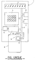
- FIG. unique is a schematic and synoptic view of a control device programmable according to the invention.
- the apparatus shown in FIG. unique includes mounted, in a single box 1, a processing unit 2, for example of the type microprocessor or microcontroller, comprising a bus 3 to which are connected to an information display device 4, such as a LCD or other type screen, keyboard 5, input interface 6 designed to receive the measurement signals from a or several temperature probes (not shown) and one control interface 7 to which at least one member is connected control of one or more heaters (not shown) installed for space heating.
- a processing unit 2 for example of the type microprocessor or microcontroller, comprising a bus 3 to which are connected to an information display device 4, such as a LCD or other type screen, keyboard 5, input interface 6 designed to receive the measurement signals from a or several temperature probes (not shown) and one control interface 7 to which at least one member is connected control of one or more heaters (not shown) installed for space heating.
- the clock 8 transmits to the processing unit 2 signals of time that processing unit 2 uses to define ranges times and to order, via the command interface 7, at within each time slot thus defined, the control of a heater so that it works, for example example, either in so-called comfort mode or in so-called economic mode.
- the heater control In comfort mode, the heater control is planned to have a temperature in the premises which gives a feeling of comfort. In economy mode, the device control heating is provided to have a temperature below the previous temperature. Between these two modes, other modes can be provided, such as intermediate modes which can be determined according to other external parameters than the temperature, for example the cost of electricity, etc. Finally, other modes can also be provided such as frost protection modes or a stop mode.
- unit 2 contains data from programming which are then said to be resident. These data are planned to allow a program also contained in the unit 2 to be executed according to said data.
- This data from programming define for example the time slots and the operating modes of the heater, comfort mode, economy mode, intermediate modes, or other necessary modes order in each of the time slots thus defined.
- Unit 2 depending on the mode selected, performs the command mentioned above depending on the temperature signals delivered on the input interface 6.
- the invention acts as a time programmer.
- the input interface 6 does not exist.
- the apparatus of the invention acts as a time programmer.
- information about the operating conditions are displayed on the device 4. It can be time data, regulation temperature and / or any other information useful to the user.
- the apparatus of the invention also includes a reader 10 for cards 11, called “smart cards”.
- cards are made up a rectangular flat support, generally made of plastic, on which an electronic circuit is mounted, generally a EEPROM type memory, as well as its connection system.
- the reader 10 of the apparatus of the invention comprises a validation device 12 and a connector 13 which is provided for cooperate with the connector of any card inserted in the reader 10.
- the connector 13 is connected to the bus 3 of the processing unit 2.
- the apparatus of the invention operates as follows.
- a first mode called mode 0, no card is inserted in reader 10.
- the device works as before, that is to say that the processing unit 2 controls the interface 7 according to the temperature signals present on interface 6 and according to programming data residing in unit 2.
- the part of the keyboard 5 which relates to the data of programming is disabled so it is not possible to modify the resident programming data.
- the keypad 5 provides functionality for reading programming data or manual override functionality of the operation of the device in one of these operating modes.
- mode 1 a card 11, called a key card, is introduced in reader 10.
- the card 11 inserted has no memory or, if it has a memory, this contains either a code specific to the operating mode 1 which identifies it as a key card, i.e. a user identification code.
- the card 11 abuts against the validation device 12 which sends a signal to the processing 2, which then activates the keyboard 5.
- the modification resident programming data is then possible, this at using the keyboard 5 and the display device 4.
- device operates in mode 0 with the resident programming data as modified.
- the processing unit 2 reads this code beforehand and checks its accuracy. According to the result of this verification, the unit of treatment 2 activates or not the mode 1 of operation of the device.
- the card 11 inserted plays the role of a key to allow the user to access the programming his device.
- This key is more or less complex depending on whether the card has or does not have a code user identification.
- This key like any key, disables the programming function of the device to those who don't have it.
- a card 11 specific called program card
- This card specific has a memory in which are stored, a part, a code that identifies it as a program card and, secondly, application-specific programming data particular.
- the memory of the card 11 is connected, via the connector of the card and the complementary connector 12 of the reader 10, also via the bus 3, to processing unit 2.
- processing unit 2 When the latter reads the code card identification, it controls interface 7 according to programming data stored in the card memory program 11 introduced. In this case, the resident data is in somehow disabled.
- a card 11 is entered and the processing unit 2 is notified of this mode, for example by pressing a particular key on the keyboard 5 or by pressing a particular sequence of keys on the keyboard 5.
- the programming data stored in the memory of the inserted card are read and loaded into the processing 2.
- data resident which were previously stored in the memory of a card, for example example of a pre-programmed card which is perfectly suited to the user.
- a card 11 is entered and the processing unit 2 is notified of this mode, for example by pressing a particular key on the keyboard 5 or by pressing a particular sequence of keys on the keyboard 5.
Landscapes
- Physics & Mathematics (AREA)
- General Physics & Mathematics (AREA)
- Engineering & Computer Science (AREA)
- Automation & Control Theory (AREA)
- Control Of Resistance Heating (AREA)
- Programmable Controllers (AREA)
- Control Of Temperature (AREA)
- Stored Programmes (AREA)
- Input From Keyboards Or The Like (AREA)
Description
Claims (6)
- Appareil de commande programmable d'une installation de chauffage du type comprenant une horloge (8) et une unité de traitement (2) prévue pour commander un ou plusieurs appareils de chauffage de ladite installation en fonction de données de programmation, caractérisé en ce que lesdites données de programmation utilisées par ladite unité de traitement sont, soit des données de programmation lues dans la mémoire d'une carte (11), du type dite carte à puce, lorsqu'une telle carte (11) est introduite dans un lecteur (10) dudit appareil, soit des données de programmation résidant dans ladite unité de traitement (2) lorsqu'aucune carte n'est introduite dans ledit lecteur (10), lesdites données de programmation résidantes ne pouvant être modifiées que si une carte (11), dite carte clef, est introduite dans le lecteur (10).
- Appareil selon la revendication 1, caractérisé en ce qu'il fonctionne dans un mode où les données de programmation contenues dans la mémoire d'une carte introduite dans le lecteur (10) sont chargées dans l'unité de traitement (2) afin de les rendre résidantes.
- Appareil selon la revendication 1 ou 2, caractérisé en ce qu'il fonctionne dans un mode où les données de programmation résidantes sont transférées dans la mémoire de la carte introduite dans le lecteur (10).
- Appareil selon une des revendications précédentes, caractérisé en ce que les mémoires des cartes qui contiennent des données de programmation contiennent également des données qui les identifient en tant que carte de programme.
- Appareil selon une des revendications précédentes, caractérisé en ce que les mémoires des cartes dites cartes clefs contiennent un code les identifiant en tant que cartes clefs.
- Appareil selon une des revendications précédentes, caractérisé en ce que les mémoires des cartes dites cartes clefs contiennent un code d'identification de l'utilisateur.
Applications Claiming Priority (2)
| Application Number | Priority Date | Filing Date | Title |
|---|---|---|---|
| FR9313609A FR2712381B1 (fr) | 1993-11-09 | 1993-11-09 | Appareil de commande programmable d'une installation de chauffage. |
| FR9313609 | 1993-11-09 |
Publications (2)
| Publication Number | Publication Date |
|---|---|
| EP0652502A1 EP0652502A1 (fr) | 1995-05-10 |
| EP0652502B1 true EP0652502B1 (fr) | 1999-02-24 |
Family
ID=9452867
Family Applications (1)
| Application Number | Title | Priority Date | Filing Date |
|---|---|---|---|
| EP94460040A Expired - Lifetime EP0652502B1 (fr) | 1993-11-09 | 1994-11-08 | Appareil de commande programmable d'une installation de chauffage |
Country Status (8)
| Country | Link |
|---|---|
| US (1) | US5805443A (fr) |
| EP (1) | EP0652502B1 (fr) |
| AT (1) | ATE176955T1 (fr) |
| AU (1) | AU688381B2 (fr) |
| CA (1) | CA2135341C (fr) |
| DE (1) | DE69416637T2 (fr) |
| ES (1) | ES2128531T3 (fr) |
| FR (1) | FR2712381B1 (fr) |
Families Citing this family (34)
| Publication number | Priority date | Publication date | Assignee | Title |
|---|---|---|---|---|
| IT1282141B1 (it) | 1996-04-29 | 1998-03-12 | Claber Spa | Centralina di controllo per impianto di irrigazione |
| DK0824879T3 (da) * | 1996-08-16 | 1999-10-25 | Olymp Karl Herzog Gmbh & Co | Elektronisk styre- og elektronisk udlæseindretning til hårbehandling samt apparat til varmebehandling af hår |
| NO320087B1 (no) * | 1997-02-10 | 2005-10-24 | Inventio Ag | Fremgangsmate og anordning ved installasjon og vedlikehold av heisanlegg |
| EP0857684B1 (fr) * | 1997-02-10 | 2002-10-23 | Inventio Ag | Méthode et dispositif pour installer et entretenir les contrôleurs d'installations d'ascenseurs |
| US6256378B1 (en) * | 1999-01-22 | 2001-07-03 | Pointset Corporation | Method and apparatus for setting programmable features of an appliance |
| US6415023B2 (en) * | 1999-01-22 | 2002-07-02 | Pointset Corporation | Method and apparatus for setting programmable features of an appliance |
| US6483906B1 (en) | 1999-01-22 | 2002-11-19 | Pointset Corporation | Method and apparatus for setting programmable features of an appliance |
| US7415102B2 (en) | 1999-01-22 | 2008-08-19 | Pointset Corporation | Method and apparatus for setting programmable features of an appliance |
| US7289611B2 (en) * | 1999-01-22 | 2007-10-30 | Pointset Corporation | Method and apparatus for setting programmable features of motor vehicle |
| US6882712B1 (en) | 1999-01-22 | 2005-04-19 | Pointset Corporation | Method and apparatus for setting programmable features of an appliance |
| DE19909674A1 (de) * | 1999-03-05 | 2000-09-07 | Satronic Ag Dielsdorf | Steuerungsvorrichtung sowie Speicherkarte für eine Steuerungsvorrichtung |
| US6498955B1 (en) * | 1999-03-19 | 2002-12-24 | Accenture Llp | Member preference control of an environment |
| US6281820B1 (en) | 1999-07-12 | 2001-08-28 | Pointset Corporation | Methods and apparatus for transferring data from a display screen |
| US6360955B1 (en) * | 1999-07-16 | 2002-03-26 | Iowa State University Research Foundation, Inc. | Method and means for automated variable heater control for agricultural unit heaters |
| US6330806B1 (en) | 2000-03-03 | 2001-12-18 | York International Corporation | System and method for controlling an HVAC system using a flash mini-card |
| US6741915B2 (en) * | 2001-08-22 | 2004-05-25 | Mmi Controls, Ltd. | Usage monitoring HVAC control system |
| US7555364B2 (en) | 2001-08-22 | 2009-06-30 | MMI Controls, L.P. | Adaptive hierarchy usage monitoring HVAC control system |
| WO2003040839A1 (fr) * | 2001-10-22 | 2003-05-15 | Smart Systems Technologies, Inc. | Systeme programmable et extensible de commande et d'automatisation de construction |
| FR2836728B1 (fr) * | 2002-03-04 | 2005-06-24 | Rain Bird Europ Sarl | Nouveau concept de programmateur d'arrosage irrigation dont le programme est inscrit sur un support exterieur |
| FR2838288B1 (fr) * | 2002-03-04 | 2005-11-25 | Rain Bird Europ Sarl | Procede et dispositif de programmation pour une installation d'arrosage ou d'irrigation et une telle installation |
| US20050090915A1 (en) * | 2002-10-22 | 2005-04-28 | Smart Systems Technologies, Inc. | Programmable and expandable building automation and control system |
| US20050194456A1 (en) | 2004-03-02 | 2005-09-08 | Tessier Patrick C. | Wireless controller with gateway |
| FR2878043B1 (fr) * | 2004-11-12 | 2007-03-23 | Briot Internat Sa | Systeme de chargement d'informations dans une machine automatisee de taille d'un verre optique a partir d'une ebauche |
| WO2007098322A2 (fr) * | 2006-02-10 | 2007-08-30 | Aronstam Peter S | Appareil et méthodes d'utilisation de contrôleurs programmables basés sur carte |
| WO2007149499A2 (fr) * | 2006-06-20 | 2007-12-27 | Kohl Tony E | dispositif d'indication configurable et procédé pour la surveillance et la commande dans des circuits de fluides |
| CN101518153A (zh) * | 2006-09-12 | 2009-08-26 | 皇家飞利浦电子股份有限公司 | 用于选择和控制光设定的系统 |
| US9310089B2 (en) | 2009-05-21 | 2016-04-12 | Lennox Industries Inc. | Variable speed motor control method and apparatus |
| CA2716304A1 (fr) * | 2010-01-27 | 2011-07-27 | Lennox Industries Inc. | Verification de l'entretien d'installations cvca par cle usb |
| CA2716303A1 (fr) * | 2010-01-27 | 2011-07-27 | Lennox Industries Inc. | Systeme de profil de l'equipement du client pour les dispositifs de commandes de cvca |
| US9008846B2 (en) | 2012-07-25 | 2015-04-14 | International Controls And Measurements Corporation | Lock-setting thermostat with flash-memory key |
| CN103604160B (zh) * | 2013-11-28 | 2016-06-15 | 济南明湖建筑节能技术开发有限公司 | 一种无线一拖一暖气阀室外控制装置 |
| GB2539910B (en) * | 2015-06-30 | 2018-11-28 | Lmk Thermosafe Ltd | Temperature controller |
| CN109915927B (zh) * | 2018-07-10 | 2021-03-02 | 李小兰 | 暖气片供暖水体排水调速平台 |
| CN109915931B (zh) * | 2018-07-25 | 2021-02-26 | 临海市小核桃工业设计服务部 | 扩展型钢铝复合暖气管 |
Family Cites Families (13)
| Publication number | Priority date | Publication date | Assignee | Title |
|---|---|---|---|---|
| US4968864A (en) * | 1978-06-05 | 1990-11-06 | Keiichiro Doi | Magnetic card control microwave oven |
| NZ193067A (en) * | 1979-06-05 | 1983-05-31 | American Sterilizer Co | Programmable sterilising apparatus |
| JPS56935A (en) * | 1979-06-15 | 1981-01-08 | Matsushita Electric Ind Co Ltd | High-frequency heating device |
| JPS6044568B2 (ja) * | 1980-02-04 | 1985-10-04 | 三洋電機株式会社 | 電子レンジ |
| US4319712A (en) * | 1980-04-28 | 1982-03-16 | Ofer Bar | Energy utilization reduction devices |
| DE3312113A1 (de) * | 1983-04-02 | 1984-10-25 | Bertold Dr. 7300 Esslingen Romacker | Temperaturregeleinrichtung fuer einzelraeume |
| US4634846A (en) * | 1984-05-22 | 1987-01-06 | American District Telegraph Company | Multimode programmable stand-alone access control system |
| DE3782114D1 (de) * | 1986-01-31 | 1992-11-12 | Electrolux Ag | Verfahren zum stellen der heizleistung an einem wechselstrombetriebenen kochherd-heizelement und steuerung fuer die heizleistung eines derartigen heizelementes. |
| JPH0816561B2 (ja) * | 1988-01-05 | 1996-02-21 | 三菱重工業株式会社 | 冷凍装置の制御装置 |
| CA1301334C (fr) * | 1988-02-08 | 1992-05-19 | Pitney Bowes Inc. | Systeme de comptabilisation des droits postaux |
| JPH04141A (ja) * | 1990-04-16 | 1992-01-06 | Hitachi Ltd | 空気調和システム |
| US5203497A (en) * | 1991-12-20 | 1993-04-20 | Honeywell Inc. | Communicating thermostat |
| JP2799809B2 (ja) * | 1993-02-16 | 1998-09-21 | 株式会社日立製作所 | 空調管理システム |
-
1993
- 1993-11-09 FR FR9313609A patent/FR2712381B1/fr not_active Expired - Lifetime
-
1994
- 1994-11-08 AT AT94460040T patent/ATE176955T1/de not_active IP Right Cessation
- 1994-11-08 DE DE69416637T patent/DE69416637T2/de not_active Expired - Fee Related
- 1994-11-08 CA CA002135341A patent/CA2135341C/fr not_active Expired - Fee Related
- 1994-11-08 ES ES94460040T patent/ES2128531T3/es not_active Expired - Lifetime
- 1994-11-08 EP EP94460040A patent/EP0652502B1/fr not_active Expired - Lifetime
- 1994-11-09 AU AU77698/94A patent/AU688381B2/en not_active Ceased
-
1997
- 1997-01-17 US US08/785,701 patent/US5805443A/en not_active Expired - Fee Related
Also Published As
| Publication number | Publication date |
|---|---|
| CA2135341C (fr) | 2001-02-20 |
| DE69416637D1 (de) | 1999-04-01 |
| EP0652502A1 (fr) | 1995-05-10 |
| DE69416637T2 (de) | 1999-06-24 |
| FR2712381B1 (fr) | 1996-02-02 |
| ATE176955T1 (de) | 1999-03-15 |
| AU7769894A (en) | 1995-05-18 |
| ES2128531T3 (es) | 1999-05-16 |
| FR2712381A1 (fr) | 1995-05-19 |
| US5805443A (en) | 1998-09-08 |
| CA2135341A1 (fr) | 1995-05-10 |
| AU688381B2 (en) | 1998-03-12 |
Similar Documents
| Publication | Publication Date | Title |
|---|---|---|
| EP0652502B1 (fr) | Appareil de commande programmable d'une installation de chauffage | |
| WO1994009570A1 (fr) | Boitier de telecommande avec une carte a memoire amovible | |
| EP0241504A1 (fr) | Dispositif personnel d'identification | |
| CH690048A5 (fr) | Dispositif de sécurité commandant l'accès à un ordinateur ou à un terminal de réseau. | |
| WO2004053786A1 (fr) | Carte a puce a affichage remanent utilisant une encre electronique sensible a la temperature | |
| EP3387395A1 (fr) | Appareil de pesage electronique equipe d'un sur-plateau | |
| FR2618927A1 (fr) | Dispositif electronique portatif | |
| FR2650426A1 (fr) | Aide-memoire pour l'affichage programme de la posologie d'un medicament a une heure determinee | |
| FR2766939A1 (fr) | Procede et appareil de simulation des caracteristiques de dispositifs a semi-conducteur | |
| JP2659213B2 (ja) | 接触型指紋検出装置 | |
| FR2496925A1 (fr) | Dispositif de programmation de regulation de chauffage | |
| FR2631467A1 (fr) | Dispositif central d'autorisation de fonctionnement individuel de plusieurs appareils de location disperses | |
| Leoniak et al. | Measuring light-switching behavior using an occupancy and light data logger | |
| EP0946918B1 (fr) | Dispositif electronique portable avec ecran d'affichage selon plusieurs directions | |
| FR2665504A1 (fr) | Systeme d'autorisation de fonctionnement d'un organe commande, notamment d'une electrovanne de distribution d'eau sanitaire. | |
| EP0139361A2 (fr) | Instrument pour mesurer des fonctions de température | |
| FR2731818A1 (fr) | Lecteur portatif pour carte a puce | |
| JPS61296240A (ja) | 尿糖測定装置 | |
| JP2800129B2 (ja) | 食堂システムの磁気カードリーダ装置 | |
| FR2698469A1 (fr) | Support amovible d'informations à utilisation contrôlée. | |
| FR2700626A1 (fr) | Procédé de fabrication d'un boîtier de télécommande de diverses fonctions d'un appareil, et boîtier de télécommande obtenu par ce procédé. | |
| WO2002045052A1 (fr) | Dispositif vocal portable multi-fonctions | |
| FR2778776A1 (fr) | Dispositif d'affichage numerique de prix pour produits frais | |
| Gala | Oral health status of older male veterans in long-term care | |
| Glazier | Work satisfaction among nurse case managers: pilot study of an instrument |
Legal Events
| Date | Code | Title | Description |
|---|---|---|---|
| PUAI | Public reference made under article 153(3) epc to a published international application that has entered the european phase |
Free format text: ORIGINAL CODE: 0009012 |
|
| AK | Designated contracting states |
Kind code of ref document: A1 Designated state(s): AT BE CH DE DK ES GB IE IT LI LU NL PT SE |
|
| 17P | Request for examination filed |
Effective date: 19951110 |
|
| GRAG | Despatch of communication of intention to grant |
Free format text: ORIGINAL CODE: EPIDOS AGRA |
|
| GRAG | Despatch of communication of intention to grant |
Free format text: ORIGINAL CODE: EPIDOS AGRA |
|
| GRAH | Despatch of communication of intention to grant a patent |
Free format text: ORIGINAL CODE: EPIDOS IGRA |
|
| 17Q | First examination report despatched |
Effective date: 19980311 |
|
| GRAH | Despatch of communication of intention to grant a patent |
Free format text: ORIGINAL CODE: EPIDOS IGRA |
|
| GRAA | (expected) grant |
Free format text: ORIGINAL CODE: 0009210 |
|
| ITF | It: translation for a ep patent filed |
Owner name: PROROGA CONCESSA IN DATA: 24.03.99;BARZANO' E ZANA |
|
| AK | Designated contracting states |
Kind code of ref document: B1 Designated state(s): AT BE CH DE DK ES GB IE IT LI LU NL PT SE |
|
| REF | Corresponds to: |
Ref document number: 176955 Country of ref document: AT Date of ref document: 19990315 Kind code of ref document: T |
|
| REG | Reference to a national code |
Ref country code: CH Ref legal event code: EP |
|
| GBT | Gb: translation of ep patent filed (gb section 77(6)(a)/1977) |
Effective date: 19990224 |
|
| REG | Reference to a national code |
Ref country code: IE Ref legal event code: FG4D Free format text: FRENCH |
|
| REF | Corresponds to: |
Ref document number: 69416637 Country of ref document: DE Date of ref document: 19990401 |
|
| REG | Reference to a national code |
Ref country code: CH Ref legal event code: NV Representative=s name: E. BLUM & CO. PATENTANWAELTE |
|
| REG | Reference to a national code |
Ref country code: ES Ref legal event code: FG2A Ref document number: 2128531 Country of ref document: ES Kind code of ref document: T3 |
|
| PG25 | Lapsed in a contracting state [announced via postgrant information from national office to epo] |
Ref country code: PT Free format text: LAPSE BECAUSE OF FAILURE TO SUBMIT A TRANSLATION OF THE DESCRIPTION OR TO PAY THE FEE WITHIN THE PRESCRIBED TIME-LIMIT Effective date: 19990524 Ref country code: DK Free format text: LAPSE BECAUSE OF FAILURE TO SUBMIT A TRANSLATION OF THE DESCRIPTION OR TO PAY THE FEE WITHIN THE PRESCRIBED TIME-LIMIT Effective date: 19990524 |
|
| PLBE | No opposition filed within time limit |
Free format text: ORIGINAL CODE: 0009261 |
|
| STAA | Information on the status of an ep patent application or granted ep patent |
Free format text: STATUS: NO OPPOSITION FILED WITHIN TIME LIMIT |
|
| 26N | No opposition filed | ||
| REG | Reference to a national code |
Ref country code: GB Ref legal event code: IF02 |
|
| PGFP | Annual fee paid to national office [announced via postgrant information from national office to epo] |
Ref country code: NL Payment date: 20061110 Year of fee payment: 13 |
|
| PGFP | Annual fee paid to national office [announced via postgrant information from national office to epo] |
Ref country code: AT Payment date: 20061113 Year of fee payment: 13 |
|
| PGFP | Annual fee paid to national office [announced via postgrant information from national office to epo] |
Ref country code: SE Payment date: 20061114 Year of fee payment: 13 Ref country code: LU Payment date: 20061114 Year of fee payment: 13 Ref country code: CH Payment date: 20061114 Year of fee payment: 13 |
|
| PGFP | Annual fee paid to national office [announced via postgrant information from national office to epo] |
Ref country code: IE Payment date: 20061123 Year of fee payment: 13 |
|
| PGFP | Annual fee paid to national office [announced via postgrant information from national office to epo] |
Ref country code: GB Payment date: 20061127 Year of fee payment: 13 |
|
| PGFP | Annual fee paid to national office [announced via postgrant information from national office to epo] |
Ref country code: IT Payment date: 20061130 Year of fee payment: 13 |
|
| PGFP | Annual fee paid to national office [announced via postgrant information from national office to epo] |
Ref country code: BE Payment date: 20061214 Year of fee payment: 13 |
|
| REG | Reference to a national code |
Ref country code: CH Ref legal event code: PFA Owner name: DELTA DORE SOCIETE ANONYME Free format text: DELTA DORE SOCIETE ANONYME#LE VIEUX CHENE BONNEMAIN#F-35270 COMBOURG (FR) -TRANSFER TO- DELTA DORE SOCIETE ANONYME#LE VIEUX CHENE BONNEMAIN#F-35270 COMBOURG (FR) |
|
| BERE | Be: lapsed |
Owner name: S.A. *DELTA DORE Effective date: 20071130 |
|
| EUG | Se: european patent has lapsed | ||
| GBPC | Gb: european patent ceased through non-payment of renewal fee |
Effective date: 20071108 |
|
| PG25 | Lapsed in a contracting state [announced via postgrant information from national office to epo] |
Ref country code: LI Free format text: LAPSE BECAUSE OF NON-PAYMENT OF DUE FEES Effective date: 20071130 Ref country code: CH Free format text: LAPSE BECAUSE OF NON-PAYMENT OF DUE FEES Effective date: 20071130 |
|
| REG | Reference to a national code |
Ref country code: CH Ref legal event code: PL |
|
| NLV4 | Nl: lapsed or anulled due to non-payment of the annual fee |
Effective date: 20080601 |
|
| REG | Reference to a national code |
Ref country code: IE Ref legal event code: MM4A |
|
| PG25 | Lapsed in a contracting state [announced via postgrant information from national office to epo] |
Ref country code: AT Free format text: LAPSE BECAUSE OF NON-PAYMENT OF DUE FEES Effective date: 20071108 |
|
| PG25 | Lapsed in a contracting state [announced via postgrant information from national office to epo] |
Ref country code: BE Free format text: LAPSE BECAUSE OF NON-PAYMENT OF DUE FEES Effective date: 20071130 |
|
| PG25 | Lapsed in a contracting state [announced via postgrant information from national office to epo] |
Ref country code: SE Free format text: LAPSE BECAUSE OF NON-PAYMENT OF DUE FEES Effective date: 20071109 Ref country code: NL Free format text: LAPSE BECAUSE OF NON-PAYMENT OF DUE FEES Effective date: 20080601 Ref country code: IE Free format text: LAPSE BECAUSE OF NON-PAYMENT OF DUE FEES Effective date: 20071108 |
|
| PG25 | Lapsed in a contracting state [announced via postgrant information from national office to epo] |
Ref country code: GB Free format text: LAPSE BECAUSE OF NON-PAYMENT OF DUE FEES Effective date: 20071108 |
|
| PGFP | Annual fee paid to national office [announced via postgrant information from national office to epo] |
Ref country code: DE Payment date: 20081121 Year of fee payment: 15 |
|
| PGFP | Annual fee paid to national office [announced via postgrant information from national office to epo] |
Ref country code: ES Payment date: 20081121 Year of fee payment: 15 |
|
| PG25 | Lapsed in a contracting state [announced via postgrant information from national office to epo] |
Ref country code: LU Free format text: LAPSE BECAUSE OF NON-PAYMENT OF DUE FEES Effective date: 20071108 Ref country code: IT Free format text: LAPSE BECAUSE OF NON-PAYMENT OF DUE FEES Effective date: 20071108 |
|
| PG25 | Lapsed in a contracting state [announced via postgrant information from national office to epo] |
Ref country code: DE Free format text: LAPSE BECAUSE OF NON-PAYMENT OF DUE FEES Effective date: 20100601 |
|
| REG | Reference to a national code |
Ref country code: ES Ref legal event code: FD2A Effective date: 20110329 |
|
| PG25 | Lapsed in a contracting state [announced via postgrant information from national office to epo] |
Ref country code: ES Free format text: LAPSE BECAUSE OF NON-PAYMENT OF DUE FEES Effective date: 20110316 |
|
| PG25 | Lapsed in a contracting state [announced via postgrant information from national office to epo] |
Ref country code: ES Free format text: LAPSE BECAUSE OF NON-PAYMENT OF DUE FEES Effective date: 20091109 |