EP0651206A1 - Ignition device - Google Patents
Ignition device Download PDFInfo
- Publication number
- EP0651206A1 EP0651206A1 EP93913671A EP93913671A EP0651206A1 EP 0651206 A1 EP0651206 A1 EP 0651206A1 EP 93913671 A EP93913671 A EP 93913671A EP 93913671 A EP93913671 A EP 93913671A EP 0651206 A1 EP0651206 A1 EP 0651206A1
- Authority
- EP
- European Patent Office
- Prior art keywords
- housing
- air
- fuel
- flare
- circular
- Prior art date
- Legal status (The legal status is an assumption and is not a legal conclusion. Google has not performed a legal analysis and makes no representation as to the accuracy of the status listed.)
- Withdrawn
Links
Images

Classifications
-
- F—MECHANICAL ENGINEERING; LIGHTING; HEATING; WEAPONS; BLASTING
- F23—COMBUSTION APPARATUS; COMBUSTION PROCESSES
- F23D—BURNERS
- F23D99/00—Subject matter not provided for in other groups of this subclass
-
- F—MECHANICAL ENGINEERING; LIGHTING; HEATING; WEAPONS; BLASTING
- F23—COMBUSTION APPARATUS; COMBUSTION PROCESSES
- F23D—BURNERS
- F23D14/00—Burners for combustion of a gas, e.g. of a gas stored under pressure as a liquid
- F23D14/02—Premix gas burners, i.e. in which gaseous fuel is mixed with combustion air upstream of the combustion zone
-
- F—MECHANICAL ENGINEERING; LIGHTING; HEATING; WEAPONS; BLASTING
- F23—COMBUSTION APPARATUS; COMBUSTION PROCESSES
- F23D—BURNERS
- F23D2207/00—Ignition devices associated with burner
Definitions
- the present invention relates to means of lightning up burners of power boiler units, petrochemical plants as well as other furnace plants, and, more specifically, to ignition devices.
- the known iginition devices are marked first of all by an inadequately well organized operational process.
- Said ignition devices display a low reliability of operation: a part of the flare is concealed in the housing, which reduces the effectiveness of the thermo-chemical effect on the flare to be ignited; a low-pressure flare is insufficiently stable in cocurrent flows and more so in deviating flows, with the ignition device located at an angle to the burner axis; there is a possibility of explosions in the ignition device housing during an attempt to trigger it, which reduces the reliabilty in the flare formation by the ignition device; a dependence of the ignition device operational mode and the reliability of its inflammation on the pressure in the furnace.
- Ignition devices with internal burning require a higher air pressure since they have to overcome losses in the total pressure, associated with the heat release inside the through part of the ignition device.
- Any attempts to increase the length of the ignition devices with internal burning for the burners of power boilers of a high capacity the required length of ignition devices can amount up to 5000 mm) has resulted in problems, incident to the dynamic instability of the process, during which, as a rule, there are two types of instability observed: periodic (monotonic drawing-in of the flare inside the housing of the device) and oscillatory instability, when low-frequency sound oscillations are generated, accompanied by oscillations of the flare (instability of the thermo-acoustic nature).
- the ionization indicators are sensitive to the presence of condensate and moisture in the flow, running through the ignition device, whereas the optical annunciators are sensitive to other sources of radiation in addition to the flare to be checked.
- an ignition device comprising a housing, a branch pipe supplying a flammable mixture, and a combustion chamber with a circular partition, provided with holes for transfer of the mixture into the chamber, a flame-conductor, made up in a shape of a perforated pipe with stabilizing head-pieces on its side end, a means of making a flare, having a form of a nozzle and a stabilizing washer, mounted in the housing after the flame-conductor side end, an inspection eye-piece and a hole to fire the mixture, manufactured in the combustion chamber housing (SU- A- 932116).
- the device operates as follows.
- a mixture prepared of gas and air is supplied into the branch pipe; a part of the mixture gets via a hole of a circular partition into the combustion chamber, while the other part flows through a perforated pipe of the flame-conductor, and in the process the gas-air mixture gets inside the housing via a hole in the pipe.
- the mixture in said chamber starts burning and the flame extends down the flow in the circular channel, formed by the internal surface of the housing and the external surface of the flame-conductor. Further, the flame transfer results in the ignition of the mixture, flowing out of the flame-conductor pipe, a stable burning is maintained by stabilizing head-pieces.
- the ignition of the mixture is accomplished via a hole from an external source of flame, which can be provided only in case the ignition device is mounted in the furnace, where a low rarefaction is effective. In case the furnace operates under pressure charging or on a balanced draft, ignition is difficult to be achieved.
- Said ignition device displays a low reliability in operation, that is in functioning as an ignition device (detonations of the mixture are possible in the housing, since the pipe of the flame-conductor and the internal channel of the device are filled with a gas-air mixture of one and the same composition approximately with a stoichiometric gas-air ratio, insufficiently full utilization of the flame, since the most effective root part of the latter is concealed in the housing; a low total pressure in the flare, and, as a result, its breaks in the cocurrent and deviating flows; a low design reliability (the heating of the outlet part of the ignition device, deposition of soot particles and dust on the inspection eye-piece), and also it has a limited length, pertaining to unfeasibility of the flame transfer to a great distances in the circular channel, formed by the perforated pipe of the flame-conductor and the housing, since a flow rate in the circular channel is increased because of the distribution of the mass coming through the pipe opening, and after the flow rate becomes equal to a certain value
- an ignition device comprising a housing with air branch pipes supplying air and gas fuel to the housing cavity, a flare forming means at the operating side end of the housing and a detonation pipe, an inlet end of which is linked with the housing cavity, its outlet end is located in the zone of the gas-air mixture outlet from the housing cavity, and which is equipped with an electrical ignition plug, connected to a high-voltage source (SU, A, 1121547).
- a high-voltage source SU, A, 1121547
- the device operates as follows.
- Air and gas are supplied into the housing and a detonation pipe with internal burning. Because of the impulse nature of burning in the pipe and characteristic jumps of pressure in it, a detonation wave is formed in the pipe. At the pipe outlet a short-time flame (discharge) appears that ignites the gas-air flow. The discharge takes place in a semiclosed volume, limited by the walls of the housing, nozzle and a fire-interception grate. Burning proceeds in the ceramic channel behind the nozzle. The flare of the ignition device is recorded by a photo sensor.
- the means of flare shaping in said device are a nozzle, fire-interception grate and a ceramic channel, disposed after them.
- Said device in comparison with the aforedescribed ignition device is not sensitive to the furnace pressure, since it is equipped with a reliable air ventilation of the detonation pipe at any pressure differentials.
- the length of the detonation pipe, and along with it the length of the whole device, is considerably greater and the rate of flow inside the detonation pipe is constant along its length.
- the flare shaping means having the form of a nozzle, a fire-interception grate and a ceramic tunnel, operates so that during ignition of the mixture in the space between the nozzle and the grate the products of combustion escape from the nozzle, getting into the eddy zones behind the grate, which hinders the delivery of fresh fuel-air mixture into said eddy zones and thus reduces the reliability of ignition and operation.
- the device does not ensure against breaks of flare during the repeated operation of the detonation pipe.
- thermo-chemical action of the ignition device on the flow to be ignited is reduced thanks to the concealment of the root, most active part of the flare in the ceramic tunnel.
- Said device features a low design reliability, associated with the heating of the ignition device elements by the flare and the effect of the products of combustion, soot particles and other products of thermal destruction of the fuel on the flare presence indicator.
- the foundation of the present invention is a purpose of creating an ignition device with a flare forming means, made up so as to considerably increase the reliability of said device functioning and structural manufacture, to increase the degree of the thermo-chemical effect on the flare of a burner to be fired, to ensure the stability of the ignition device flare in cocurrent and deviating flows, and, as a consequence, to reduce the time required for firing and starting up burner devices, to exclude a possibility of explosions in the furnace chambers in the course of automatically controlled firing and to reduce the operational expenses for maintenance.
- said ignition device comprising a housing with air and gas supply branch pipes into the housing cavity, a flare forming means at the operating side end of the housing and a detonation pipe, the inlet end of which is linked with the housing cavity and the outlet end of which is disposed in the zone of the gas-air flow outlet in the housing cavity and which is equipped with an electrical ignition plug, connected to a high-voltage source with the flare forming means made as a generator of an intermittent-circular fuel-air mixture stream.
- the intermittent-circular fuel-air mixture stream generator is preferably manufactured as a partition, having a shape of an axisymmetrical body of revolution, provided with through holes around the circumference, located along the circular line, and a flat side end from the side of the fuel-air mixture flow outlet.
- the through channels can be made as holes in the disk body, disposing them in line with said body.
- the partition can also have a shape of a two-stage cylinder, whereas the through hole can be manufactured as grooves in the body of a stage with a bigger diameter, disposed from the side of the housing cavity.
- the device with a mixing chamber, located outside of the housing and linked with said chamber by means of an air by-pass branch pipe, equipped with a metering orifice, and a fuel-air mixture by-pass branch pipe, with the inlet end of the detonation pipe, appropriately located in the mixing chamber, while the outlet end of said detonation pipe, located in the additional channel, made in the partition body in a close vicinity to one of the through channels and in line with the latter.
- the device with a flare presence indicator, made as a contact thermo-sensitive element, disposed on the flat side end of the intermittent-circular stream generator and in line with the latter.
- the applied ignition device ensures a reduction in losses, associated with a breakage or an idle time during repairs of the expensive power equipment due to explosions in furnaces of the fuel-air mixtures, and makes it possible to considerably reduce the operational expenses (high overhaul service life, insensitivity to pressure changes in the furnace, reliable selective flame checking).
- the applied device permits also the reduction of fuel consumption in the course of firing thanks to the reduction of time, required for the ignition of burners and the automation of the firing procedure, as well as the reduction of operational expenses, associated with the absence of separate air pressure sources (compressors, oil and moisture separators) and with a possibility of work with low-head forced-draft fans of the furnace plant.
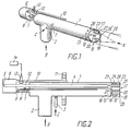
- An ignition device comprises a housing 1 (Figs.1 and 2), having a branch pipe 2 supplying air to the housing 1 cavity along arrow B and a branch pipe 3 supplying gas fuel to the housing 1 cavity along arrow C.
- a detonation pipe 4 (Fig.2), an inlet 5 of which via a mixing chamber 6 is linked with a fuel-air mixture by-pass branch pipe 7 from the cavity of the housing 1.
- the mixing chamber 6 is connected with the housing 1 by means of an air by-pass branch pipe 8, having at the inlet to the chamber 6 a metering orifice 9, and is connected with a draining branch pipe 10, mounted outside the housing 1 and fixed on a flange 11.
- the closest to the inlet 5 part 12 of the pipe 4 is disposed outside the housing 1.
- the part 12 of the pipe 4 mounts the electrical ignition plug 13, connected to a high-voltage source 14.
- the cavity of the housing 1 accomodates a flare shaping means 15, disposed from the side of an operating side end 16 of the housing 1 and a flare presence indicator 17.
- the flare shaping means 15 (Figs.1 and 2) is made up as an fuel-air mixture intermittent-circular stream generator 18.
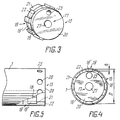
- the generator 18 (Figs.1 to 3) where the fuel-air intermittent-circular stream is produced is a partition, having a form of an axisymmetrical body of revolution, provided with through channels 19 around the periphery, located on the circular line, and a flat side end 20 from the side of the fuel-air mixture stream outlet.
- the partition is made up as a disk with stages, having a stage 21 of a greater diameter, disposed from the side of the housing 1 surface, and a stage 22 of a smaller diameter, having a flat side end 20.
- the through channels are manufactured as grooves 19 in the stage 21 body.
- the outlet 23 (Fig.2) of the detonation pipe 4 is located in the channel 24, made in the partition body in a close vicinity to one of the through channels 19 (grooves 19'), as is shown in Fig.4.
- radial holes 26 (Fig.5) appropriate to the number of the grooves 19', disposed opposite to the middle of the spans between the grooves 19'.
- the flare presence indicator 17 (Figs.2 and 6) of the ignition device according to the invention is made in a form of a contact thermo-sensitive element 27, mounted on the flat side end 20 of the axisymmetrical body of revolution of the intermittent-circular stream generator 18 in line with the latter, thanks to which provided is a checking selectivity of the ignition device flare.
- the aforedescribed embodiment of the invention is expediently employed for firing the furnace burners of steam and water-heating boilers of different capacities, operating under pressurization or with a balanced draft as well as in the automatically controlled systems for explosion-proof ignition of the furnace chambers in energetics and other spheres, requiring reliable firing and stable checking of the flame.
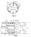
- the body of revolution of the intermittent-circular fuel-air mixture stream generator 18 (Fig.7) is in the shape of a disk 28, whereas the through channels have a form of holes 19'' in the body of said disk 28.
- the operational principle of the ignition device according to the invention consists in the following.
- Air is supplied to the branch pipe 2 (Fig.2) along the arrow B, while gas fuel is delivered to the branch pipe 3 along the arrow C.
- a rich fuel-air mixture is created in the housing 1, starting from the branch pipe 3 in the direction of the flare shaping device 15 of the ignition device, whereas from the branch pipe 2 in the direction of the mixing chamber 6 there is practically a clear air.
- the fuel-air mixture via the branch pipe 7 out of the housing 1 cavity flows into the mixing chamber 6 and becomes leaner with fresh air via the air by-pass branch pipe 8 and the metering orifice 9 until the stoichiometric ratio is obtained.
- the fuel-air mixture from the mixing chamber 6 is supplied to the inlet 5 of the detonation pipe 4.
- the fuel-air mixture from the housing 1 flows out in the shape of a thin intermittent-circular stream via the through channels 19 and also becomes leaner down to the required ratio via the radial holes 26.
- the fuel-air mixture explodes and by means of the detonation pipe 4 and the channel 24 into the return current recycling zone 29 (Fig.6) a firing shot is effected.
- the fuel-air mixture behind the operational side end 16 is ignited.
- the products of combustion, created in the process in the mixing chamber 6 (Fig.2) are drained from it via the draining branch pipe 10 and the detonation pipe 4 into the furnace chamber.
- thermo-sensitive element 27 of the flare presence indicator 17 of the ignition device is screened by a stable recycling zone 29 (Fig.6) of return currents, formed by a cool intermittent-circular fuel-air mixture flowing from the ignition device, and does not react to the flares of closely located burning devices and the radiation of the furnace chamber.
- the intermittent-circular stream directly at the outlet of the generator 18 (Fig.6), consisting of a group of individual flows, distributed along the circle at the periphery of the generator, produces a recycling zone 29 behind the generator 18, which functions as a burning stabilizer.
- Such a stabilizer operates within a wide range of rate variations of individual flow runs, with the limits of stability in the stabilizer operation depending on the height of an individual flow at the generator 18 outlet versus the diameter of the intermittent-circular stream. If required to extend the limits, said ratio should be reduced.
- Burning in the recycling zone 29 is a standby source for the flare lightning-up. Between the recycling zone 29 (Fig.8) and a flare burning visual zone 30, there is a transitional zone 31 in which the visible burning of the flare during operation on lean mixtures may be absent.
- the secondary air flows into at the portion between the intermittent-circular stream generator 18 outlet and the border of the individual flows closing into a circular stream. Thanks to this fact, the excessive air coefficient in the recycling zone 29 is always greater and the mixture is leaner than in the mouths of individual flows and in the housing of the ignition device.
- the secondary air is sucked in via radial holes 26 due to rarefaction behind the projections between the grooves 19' (Fig.6).
- the flows of the intermittent-circular stream close in into a circular stream "c" (Fig.8).
- the cross-section of the holes 26 determines the consumption of the secondary air, which is used during the adjustment of the ignition device according to the invention.
- the air by-pass branch pipe 8 (Fig.2), the flow rate through which is determined by the metering orifice 9, serves for the air delivery to the mixing chamber 6, into which at the same time is delivered a fuel-air mixture from the housing 1, thanks to which the mixture in the mixing chamber 6 becomes leaner and with a properly selected metering orifice 9 the excessive air coefficient in the mixing chamber 6 does not differ from the excessive air coefficient in the mixture, present in the recycling zone 29 (Fig.6) behind the intermittent-circular stream generator 18.
- the two-stage leaning of the mixture makes it possible to prevent mixture explosions in the housing 1.
- the first stage of leaning is common: the gas is thinned by air in the housing 1 of the ignition device.
- the second stage of leaning for the firing stream is an additional thinning of the mixture in the mixing chamber 6 (Fig.2), whereas for the main stage is sucking in of the second air along the arrow "a" (Fig.8) and along the arrow "d” (Fig.9) in case the holes 26 are absent.
- the detonation pipe outlet has a different disposition, for instance, coaxial with the intermittant-circular stream generator, the discharge takes place in opposition to the flow lines in the recycling zone, the lightning up becomes less reliable.
- the reliability and a high selectivity of the flare presence indicator 17 (Fig.6) of the ignition device are based on the specific features in operation of the flare shaping device 15.
- the essence lies in the fact that the flare can be lightened up only in case the flame impulse is delivered to the recycling zone 29, that is, under the intermittent-cicular stream. Since the recycling zone 29 is screened by a high-rate stream, the lightning up of the flare and its stable burning with no burning in the recycling zone 29 is impossible.
- thermo-sensitive element 27 performs the role of a secondary converter of information.
- thermo-sensitive element is a contact type one, that is, reacting to the ambient temperature in the recycling zone 29, is favourable to the flame check selectivity under the conditions of multi-burner furnaces.
- the mounting of the element 27 coaxially with the body of the intermittent-circular stream generator 18 makes the products of combustion in the recycling zone 29 flow in the direction of the arrow "e" over the thermo-sensitive element 27, which improves the heat-exchange conditions of the element 27 with the medium in said zone 29.
- the applied ignition device provides for a high reliability of fuctioning within a wide range of pressure variations of air and gas fuel, and excludes a probability of mixture explosions in the housing of the device.
- the employment of the intermittent-circular stream generator in said ignition device makes it possible to ensure stable burning of the flare outside the housing and at the same time provides for the operation of the ignition device with richer fuel-air mixtures which fill the housing, thereupon excluding explosions of the fuel-air mixture in the housing.
- the intermittent-circular stream generator as a metering device of the fuel-air mixture consumption, and, consequently, of the air consumption, the share of which prevails in the total consumption of the fuel-air mixture.
- a metering device By disposing such a metering device at the outlet of the ignition device and selecting a sufficiently high ratio of cross-section areas of the branch pipe 2 and the housing 1, on one part, and of the generator 18, on the other, it is possible to ensure reliable operation of the ignition device with the values of air pressure being small as well as high (the permissible range of pressure variations is over 12, for instance, of the air from 0.5 kPa to 6.0 kPa and of the natural gas from 3.0 kPa to 36 kPa ; with the air pressure being constant the pressure change of gas may not exceed 3 times, for instance, at an air pressure of 1.5 kPa, the device reliably functions at a gas pressure of from 9 kPa to 27 kPa.
- the applied device ensures a high reliability at variable pressures in furnaces of power boiler plants.
- the applied ignition device operates with a low-pressure air taken off from the outlet of the furnace forced-draft fans and other sources. A constant air flow through
- the ignition device protects the structure against over-heating during the furnace operation, which ensures a high structural reliability.
- the applied device is characterized by an absence of explosions in the housing and breaks of the flare during multiple discharges of the detonation pipe.
- the device according to the invention shows a high reliability in the course of long operation in the cocurrent and deviating flows and ensures selective checking of the flare flame, irrespective of the mode of operation of its flare.
- the ignition device can be employed preferably in the automatic furnace control systems of power boiler plants, petrochemical plants and other furnace plants, since said ignition device on command from the control system delivers an igniting flare and indicates the presence or absence of said flare irrespective of the burner mode of operation.
Abstract
An ignition device comprises a housing (1) with branch pipes (2, 3) for the delivery of air and gaseous fuel into the cavity of the housing (1) within which are mounted: a detonation tube (4), the inlet of which communicates with an outlet pipe (7) for releasing some of the fuel-air mixture from the cavity of the housing (1); a section (12) of the detonation tube close to the said inlet extending beyond the confines of the housing (1) and having mounted on it an electrical spark plug (13); a device (15) for forming a jet mounted towards the working end (16) of the housing (1); and an indicator device (17) to detect the presence of a jet. The device (15) for forming a jet is designed in the form of a generator (18) which produces a stream of fuel-air mixture in the form of a non-continuous ring.
Description
- The present invention relates to means of lightning up burners of power boiler units, petrochemical plants as well as other furnace plants, and, more specifically, to ignition devices.
- The problem of explosion-proof lightning up of burners in furnace plants of various functions remains topical up to the present days. It is associated, mainly, with the lack of reliable ignition devices and indicators which announce the presence of flares in said devices.
- The known iginition devices are marked first of all by an inadequately well organized operational process.
- Thus, for instance, in the ignition devices with burning inside the housing or behind the nozzle inside the ceramic tunnel having rod-type burning stabilizers, it is impossible to provide a sufficiently long service life and design reliability because of the structure element heating and thermal shocks during inflammation. Said ignition devices display a low reliability of operation: a part of the flare is concealed in the housing, which reduces the effectiveness of the thermo-chemical effect on the flare to be ignited; a low-pressure flare is insufficiently stable in cocurrent flows and more so in deviating flows, with the ignition device located at an angle to the burner axis; there is a possibility of explosions in the ignition device housing during an attempt to trigger it, which reduces the reliabilty in the flare formation by the ignition device; a dependence of the ignition device operational mode and the reliability of its inflammation on the pressure in the furnace.
- Ignition devices with internal burning require a higher air pressure since they have to overcome losses in the total pressure, associated with the heat release inside the through part of the ignition device. Any attempts to increase the length of the ignition devices with internal burning (for the burners of power boilers of a high capacity the required length of ignition devices can amount up to 5000 mm) has resulted in problems, incident to the dynamic instability of the process, during which, as a rule, there are two types of instability observed: periodic (monotonic drawing-in of the flare inside the housing of the device) and oscillatory instability, when low-frequency sound oscillations are generated, accompanied by oscillations of the flare (instability of the thermo-acoustic nature).
- It is especially well demonstrated in the ignition device of the eddy type, the dynamic instability of which limits the length of the ignition device to 15-20 calibers of their housing tube (750-1000 mm with the diameter of the housing being 50 mm).
- A reliable selective checking of the ignition device flare is far from being solved by this time. Popular ionization indicators and optical annuciators cannot provide for sufficient reliability under the conditions of functioning furnaces with a great amount of dust, soot particles and other products of thermal destruction of the fuel that precipitate on electrodes and optical elements.
- Besides, the ionization indicators are sensitive to the presence of condensate and moisture in the flow, running through the ignition device, whereas the optical annunciators are sensitive to other sources of radiation in addition to the flare to be checked.
- Known is an ignition device, comprising a housing, a branch pipe supplying a flammable mixture, and a combustion chamber with a circular partition, provided with holes for transfer of the mixture into the chamber, a flame-conductor, made up in a shape of a perforated pipe with stabilizing head-pieces on its side end, a means of making a flare, having a form of a nozzle and a stabilizing washer, mounted in the housing after the flame-conductor side end, an inspection eye-piece and a hole to fire the mixture, manufactured in the combustion chamber housing (SU- A- 932116).
- The device operates as follows.
- A mixture prepared of gas and air is supplied into the branch pipe; a part of the mixture gets via a hole of a circular partition into the combustion chamber, while the other part flows through a perforated pipe of the flame-conductor, and in the process the gas-air mixture gets inside the housing via a hole in the pipe. When mixture is ignited by an external source of flame, to which purpose use is made of the hole in the combustion chamber, the mixture in said chamber starts burning and the flame extends down the flow in the circular channel, formed by the internal surface of the housing and the external surface of the flame-conductor. Further, the flame transfer results in the ignition of the mixture, flowing out of the flame-conductor pipe, a stable burning is maintained by stabilizing head-pieces.
- In the above-described device the ignition of the mixture is accomplished via a hole from an external source of flame, which can be provided only in case the ignition device is mounted in the furnace, where a low rarefaction is effective. In case the furnace operates under pressure charging or on a balanced draft, ignition is difficult to be achieved.
- Said ignition device displays a low reliability in operation, that is in functioning as an ignition device (detonations of the mixture are possible in the housing, since the pipe of the flame-conductor and the internal channel of the device are filled with a gas-air mixture of one and the same composition approximately with a stoichiometric gas-air ratio, insufficiently full utilization of the flame, since the most effective root part of the latter is concealed in the housing; a low total pressure in the flare, and, as a result, its breaks in the cocurrent and deviating flows; a low design reliability (the heating of the outlet part of the ignition device, deposition of soot particles and dust on the inspection eye-piece), and also it has a limited length, pertaining to unfeasibility of the flame transfer to a great distances in the circular channel, formed by the perforated pipe of the flame-conductor and the housing, since a flow rate in the circular channel is increased because of the distribution of the mass coming through the pipe opening, and after the flow rate becomes equal to a certain value, the propagation of the flame in the circular channel becomes unstable.
- Known is an ignition device, comprising a housing with air branch pipes supplying air and gas fuel to the housing cavity, a flare forming means at the operating side end of the housing and a detonation pipe, an inlet end of which is linked with the housing cavity, its outlet end is located in the zone of the gas-air mixture outlet from the housing cavity, and which is equipped with an electrical ignition plug, connected to a high-voltage source (SU, A, 1121547).
- The device operates as follows.
- Air and gas are supplied into the housing and a detonation pipe with internal burning. Because of the impulse nature of burning in the pipe and characteristic jumps of pressure in it, a detonation wave is formed in the pipe. At the pipe outlet a short-time flame (discharge) appears that ignites the gas-air flow. The discharge takes place in a semiclosed volume, limited by the walls of the housing, nozzle and a fire-interception grate. Burning proceeds in the ceramic channel behind the nozzle. The flare of the ignition device is recorded by a photo sensor.
- The means of flare shaping in said device are a nozzle, fire-interception grate and a ceramic channel, disposed after them.
- Said device in comparison with the aforedescribed ignition device is not sensitive to the furnace pressure, since it is equipped with a reliable air ventilation of the detonation pipe at any pressure differentials. The length of the detonation pipe, and along with it the length of the whole device, is considerably greater and the rate of flow inside the detonation pipe is constant along its length.
- In said ignition device, however, the flare shaping means, having the form of a nozzle, a fire-interception grate and a ceramic tunnel, operates so that during ignition of the mixture in the space between the nozzle and the grate the products of combustion escape from the nozzle, getting into the eddy zones behind the grate, which hinders the delivery of fresh fuel-air mixture into said eddy zones and thus reduces the reliability of ignition and operation.
- Thereto, the device does not ensure against breaks of flare during the repeated operation of the detonation pipe.
- The effectivity of the thermo-chemical action of the ignition device on the flow to be ignited is reduced thanks to the concealment of the root, most active part of the flare in the ceramic tunnel.
- Said device features a low design reliability, associated with the heating of the ignition device elements by the flare and the effect of the products of combustion, soot particles and other products of thermal destruction of the fuel on the flare presence indicator.
- Therewith , a normal operation requires a high air pressure due to considerable losses of the total air pressure as a result of the gas-air mixture formation.
- The foundation of the present invention is a purpose of creating an ignition device with a flare forming means, made up so as to considerably increase the reliability of said device functioning and structural manufacture, to increase the degree of the thermo-chemical effect on the flare of a burner to be fired, to ensure the stability of the ignition device flare in cocurrent and deviating flows, and, as a consequence, to reduce the time required for firing and starting up burner devices, to exclude a possibility of explosions in the furnace chambers in the course of automatically controlled firing and to reduce the operational expenses for maintenance.
- The purpose is realized by the fact that in said ignition device, comprising a housing with air and gas supply branch pipes into the housing cavity, a flare forming means at the operating side end of the housing and a detonation pipe, the inlet end of which is linked with the housing cavity and the outlet end of which is disposed in the zone of the gas-air flow outlet in the housing cavity and which is equipped with an electrical ignition plug, connected to a high-voltage source with the flare forming means made as a generator of an intermittent-circular fuel-air mixture stream.
- The intermittent-circular fuel-air mixture stream generator is preferably manufactured as a partition, having a shape of an axisymmetrical body of revolution, provided with through holes around the circumference, located along the circular line, and a flat side end from the side of the fuel-air mixture flow outlet.
- At the same time it is advantageous to make up the partition as a disk, whereas the through channels can be made as holes in the disk body, disposing them in line with said body.
- The partition can also have a shape of a two-stage cylinder, whereas the through hole can be manufactured as grooves in the body of a stage with a bigger diameter, disposed from the side of the housing cavity.
- In this case in the housing part, located in the zone where the stage with a smaller diameter is disposed, it is desirable to have radial holes, made in correspondence with the number of grooves, with a disposition of said holes opposite to the middle of the span between grooves.
- It is preferable to provided the device with a mixing chamber, located outside of the housing and linked with said chamber by means of an air by-pass branch pipe, equipped with a metering orifice, and a fuel-air mixture by-pass branch pipe, with the inlet end of the detonation pipe, appropriately located in the mixing chamber, while the outlet end of said detonation pipe, located in the additional channel, made in the partition body in a close vicinity to one of the through channels and in line with the latter.
- It is practicable also to provide the device with a flare presence indicator, made as a contact thermo-sensitive element, disposed on the flat side end of the intermittent-circular stream generator and in line with the latter.
- Besides it is desirable to provided a draining branch pipe, connected with the mixing chamber.
- The applied ignition device ensures a reduction in losses, associated with a breakage or an idle time during repairs of the expensive power equipment due to explosions in furnaces of the fuel-air mixtures, and makes it possible to considerably reduce the operational expenses (high overhaul service life, insensitivity to pressure changes in the furnace, reliable selective flame checking).
- The applied device permits also the reduction of fuel consumption in the course of firing thanks to the reduction of time, required for the ignition of burners and the automation of the firing procedure, as well as the reduction of operational expenses, associated with the absence of separate air pressure sources (compressors, oil and moisture separators) and with a possibility of work with low-head forced-draft fans of the furnace plant.
- From now on the description of the invention will be explained by specific examples and appended drawings which show the following.
- Fig.1: General view of the ignition device according to the invention;
- Fig.2: General view of the ignition device according to the invention in longitudinal cross-section;
- Fig.3: General view of the intermittent-circular fuel-air mixture stream generator according to Figs.1 and 2 (axonometry);
- Fig.4: The same as in Fig.1, view along arrow A;
- Fig.5: A part of the housing of the device according to Figs.1 and 2, exploded side view, cut-out;
- Fig.6: The intermittent-circular fuel-air mixture stream generator of the ignition device according to Figs.1 and 2 (longitudinal cross-section) and the formation of the recirculation zone of return currents, exploded view;
- Fig.7: General view of another embodiment of the intermittent-circular fuel-air mixture stream generator (axonometry);
- Fig.8: The same as in Fig.5, side view;
- Fig.9: A part of another ignition device housing embodiment according to the invention.
- The best embodiments of the invention.
- An ignition device according to the invention comprises a housing 1 (Figs.1 and 2), having a
branch pipe 2 supplying air to thehousing 1 cavity along arrow B and abranch pipe 3 supplying gas fuel to thehousing 1 cavity along arrow C. - In the cavity of the
housing 1 there is located (partially) a detonation pipe 4 (Fig.2), aninlet 5 of which via amixing chamber 6 is linked with a fuel-air mixture by-pass branch pipe 7 from the cavity of thehousing 1. Themixing chamber 6 is connected with thehousing 1 by means of an air by-pass branch pipe 8, having at the inlet to the chamber 6 ametering orifice 9, and is connected with a drainingbranch pipe 10, mounted outside thehousing 1 and fixed on a flange 11. The closest to theinlet 5part 12 of thepipe 4 is disposed outside thehousing 1. Thepart 12 of thepipe 4 mounts theelectrical ignition plug 13, connected to a high-voltage source 14. - The cavity of the
housing 1 accomodates a flare shaping means 15, disposed from the side of an operating side end 16 of thehousing 1 and aflare presence indicator 17. - The flare shaping means 15 (Figs.1 and 2) is made up as an fuel-air mixture intermittent-
circular stream generator 18. - In the described embodiment according to Figs 1 and 2 the generator 18 (Figs.1 to 3) where the fuel-air intermittent-circular stream is produced is a partition, having a form of an axisymmetrical body of revolution, provided with through
channels 19 around the periphery, located on the circular line, and aflat side end 20 from the side of the fuel-air mixture stream outlet. - In the described embodiment, as is seen in Fig.3, the partition is made up as a disk with stages, having a
stage 21 of a greater diameter, disposed from the side of thehousing 1 surface, and astage 22 of a smaller diameter, having aflat side end 20. The through channels are manufactured asgrooves 19 in thestage 21 body. - The outlet 23 (Fig.2) of the
detonation pipe 4 is located in thechannel 24, made in the partition body in a close vicinity to one of the through channels 19 (grooves 19'), as is shown in Fig.4. - In a part 25 (Fig.2) of the
housing 1, disposed directly behind thestage 21 of a greater diameter of thegenerator 18, from the side of thestage 22 of a smaller diameter between grooves 19' there are manufactured radial holes 26 (Fig.5) appropriate to the number of the grooves 19', disposed opposite to the middle of the spans between the grooves 19'. - The flare presence indicator 17 (Figs.2 and 6) of the ignition device according to the invention is made in a form of a contact thermo-
sensitive element 27, mounted on theflat side end 20 of the axisymmetrical body of revolution of the intermittent-circular stream generator 18 in line with the latter, thanks to which provided is a checking selectivity of the ignition device flare. - The aforedescribed embodiment of the invention, according to the invention, is expediently employed for firing the furnace burners of steam and water-heating boilers of different capacities, operating under pressurization or with a balanced draft as well as in the automatically controlled systems for explosion-proof ignition of the furnace chambers in energetics and other spheres, requiring reliable firing and stable checking of the flame.
- Should the ignition devices according to the invention be intended for the employment as a permanent ignition burner, the body of revolution of the intermittent-circular fuel-air mixture stream generator 18 (Fig.7) is in the shape of a
disk 28, whereas the through channels have a form of holes 19'' in the body of saiddisk 28. - Other numerous embodiments of the intermittent-circular stream generator are also possible. What is important from the point of view of the quality of the applied device operation for said generator is that the relation of a typical tranverse dimension "h" (Fig.4) of individual flows to the typical transverse dimension "D" of the generator 18 (h/D) is small, whereas the density of individual flows (the ratio of the transverse dimension to the stream step along the circle) is sufficiently great to ensure their closing in a common circular stream. Besides, there should be no elements (protrusions) behind the
generator 18 that may have an effect on the recycling zone, therewith the side end of the generator should be better flat or concave. - The operational principle of the ignition device according to the invention consists in the following.
- Air is supplied to the branch pipe 2 (Fig.2) along the arrow B, while gas fuel is delivered to the
branch pipe 3 along the arrow C. In the process, a rich fuel-air mixture is created in thehousing 1, starting from thebranch pipe 3 in the direction of theflare shaping device 15 of the ignition device, whereas from thebranch pipe 2 in the direction of the mixingchamber 6 there is practically a clear air. Under the effect of an excessive pressure in thehousing 1 the fuel-air mixture via thebranch pipe 7 out of thehousing 1 cavity flows into the mixingchamber 6 and becomes leaner with fresh air via the air by-pass branch pipe 8 and themetering orifice 9 until the stoichiometric ratio is obtained. - Prepared in this way the fuel-air mixture from the mixing
chamber 6 is supplied to theinlet 5 of thedetonation pipe 4. At the same time the fuel-air mixture from thehousing 1 flows out in the shape of a thin intermittent-circular stream via the throughchannels 19 and also becomes leaner down to the required ratio via the radial holes 26. - After the supply of high-voltage from the high-
voltage source 14 to theelectrical ignition plug 13, the fuel-air mixture explodes and by means of thedetonation pipe 4 and thechannel 24 into the return current recycling zone 29 (Fig.6) a firing shot is effected. The fuel-air mixture behind theoperational side end 16 is ignited. The products of combustion, created in the process in the mixing chamber 6 (Fig.2) are drained from it via the drainingbranch pipe 10 and thedetonation pipe 4 into the furnace chamber. - Under the no-burning conditions the contact thermo-
sensitive element 27 of theflare presence indicator 17 of the ignition device is screened by a stable recycling zone 29 (Fig.6) of return currents, formed by a cool intermittent-circular fuel-air mixture flowing from the ignition device, and does not react to the flares of closely located burning devices and the radiation of the furnace chamber. - In case of a discharge from the
detonation pipe 4 into the returncurrent zone 29, the mixture is lightened up, the products of combustion, having a high temperature flow over the thermo-sensitive element 27, and theindicator 17 registers the start of a flare. - The intermittent-circular stream directly at the outlet of the generator 18 (Fig.6), consisting of a group of individual flows, distributed along the circle at the periphery of the generator, produces a
recycling zone 29 behind thegenerator 18, which functions as a burning stabilizer. - Such a stabilizer operates within a wide range of rate variations of individual flow runs, with the limits of stability in the stabilizer operation depending on the height of an individual flow at the
generator 18 outlet versus the diameter of the intermittent-circular stream. If required to extend the limits, said ratio should be reduced. - Burning in the
recycling zone 29 is a standby source for the flare lightning-up. Between the recycling zone 29 (Fig.8) and a flare burningvisual zone 30, there is atransitional zone 31 in which the visible burning of the flare during operation on lean mixtures may be absent. - Under the effect of rarefaction in the
recycling zone 29 acting along arrow "a", the secondary air flows into at the portion between the intermittent-circular stream generator 18 outlet and the border of the individual flows closing into a circular stream. Thanks to this fact, the excessive air coefficient in therecycling zone 29 is always greater and the mixture is leaner than in the mouths of individual flows and in the housing of the ignition device. - The secondary air is sucked in via
radial holes 26 due to rarefaction behind the projections between the grooves 19' (Fig.6). The flows of the intermittent-circular stream close in into a circular stream "c" (Fig.8). The cross-section of theholes 26 determines the consumption of the secondary air, which is used during the adjustment of the ignition device according to the invention. - The air by-pass branch pipe 8 (Fig.2), the flow rate through which is determined by the
metering orifice 9, serves for the air delivery to the mixingchamber 6, into which at the same time is delivered a fuel-air mixture from thehousing 1, thanks to which the mixture in the mixingchamber 6 becomes leaner and with a properly selectedmetering orifice 9 the excessive air coefficient in the mixingchamber 6 does not differ from the excessive air coefficient in the mixture, present in the recycling zone 29 (Fig.6) behind the intermittent-circular stream generator 18. The synchronization of the excessive air coefficients in the mixingchamber 6 and, by doing so, in thedetonation pipe 4 with the same coefficient of excess in therecycling zone 29, results in extension of the ignition limits (with the air pressure being constant, the ratio of the gas pressure at the "rich" ingnition limit to the gas pressure at the "lean" limit amounts to 3). - Besides, the two-stage leaning of the mixture, if organized properly, makes it possible to prevent mixture explosions in the
housing 1. For the main and igniting flows, the first stage of leaning is common: the gas is thinned by air in thehousing 1 of the ignition device. The second stage of leaning for the firing stream is an additional thinning of the mixture in the mixing chamber 6 (Fig.2), whereas for the main stage is sucking in of the second air along the arrow "a" (Fig.8) and along the arrow "d" (Fig.9) in case theholes 26 are absent. When operating at small rates of the gas consumption with the mixture content in thehousing 1 of the ignition device being close to the stoichiometric one and said mixture is able to explode, the mixture in the mixing chamber 6 (Fig. 2) and thedetonation pipe 4 has become so lean, that the mixture can not be ignited by theelectrical ignition plug 13. In the course of operation with rated gas consumptions in the mixingchamber 6,detonation pipe 4 and therecycling zone 29 as well as in thehousing 1 the mixture is richer. The composition of the mixture in the mixingchamber 6,pipe 4 and therecycling zone 29 is close to the stoichiometric one, and the mixture can burn, while in thehousing 1 the mixture is overenrich and does not constitute a risk of explosion. - Should the detonation pipe 4 (Fig.2) operate in the
channel 24,a short-time impulse of flame (discharge) takes place which,with the peripherical disposition of theoutlet 23 of thedetonation pipe 4,is directed concurrently with the flow lines in the recycling zone 29 (Fig.6) thanks to which reliable lightning up of the mixture is effected in the zone and, subsequently, the lightning up of the flare as a whole. - In case the detonation pipe outlet has a different disposition, for instance, coaxial with the intermittant-circular stream generator, the discharge takes place in opposition to the flow lines in the recycling zone, the lightning up becomes less reliable.
- Due to the draining branch pipe 10 (Fig.2) an opportunity opens up to reduce the pressure impulse that accompanies the lightning up in the
detonation pipe 4, which results in a decrease of the flow rate of the products of combustion from thechannel 24 of thedetonation pipe 4 and in improvement of the mixture lightning up in the recycling zone 29 (Fig.6). - The operation of the ignition device according to the invention with the intermittent-circular stream generator 18 (Fig.7), made as
disk 28 is similar to the above described. - The reliability and a high selectivity of the flare presence indicator 17 (Fig.6) of the ignition device are based on the specific features in operation of the
flare shaping device 15. - The essence lies in the fact that the flare can be lightened up only in case the flame impulse is delivered to the
recycling zone 29, that is, under the intermittent-cicular stream. Since therecycling zone 29 is screened by a high-rate stream, the lightning up of the flare and its stable burning with no burning in therecycling zone 29 is impossible. - In case the burner of any power boiler or other furnace device operates, while the ignition device has not been lightened up by the
detonation pipe 4, the fuel-air mixture is ignited down the flow, but there is no burning in therecycling zone 29, the temperature in the zone is low and the thermo-sensitive element does not produce any signal. - There by a function of an initial converter of the selective flame check of the ignition device is performed by the
recycling zone 29, whose temperature displays the presence or absence of stable flare burning of the ignition device, whereas the thermo-sensitive element 27 performs the role of a secondary converter of information. The fact that the thermo-sensitive element is a contact type one, that is, reacting to the ambient temperature in therecycling zone 29,is favourable to the flame check selectivity under the conditions of multi-burner furnaces. - The mounting of the
element 27 coaxially with the body of the intermittent-circular stream generator 18 makes the products of combustion in therecycling zone 29 flow in the direction of the arrow "e" over the thermo-sensitive element 27, which improves the heat-exchange conditions of theelement 27 with the medium in saidzone 29. - The applied ignition device provides for a high reliability of fuctioning within a wide range of pressure variations of air and gas fuel, and excludes a probability of mixture explosions in the housing of the device.
- The employment of the intermittent-circular stream generator in said ignition device makes it possible to ensure stable burning of the flare outside the housing and at the same time provides for the operation of the ignition device with richer fuel-air mixtures which fill the housing, thereupon excluding explosions of the fuel-air mixture in the housing. Hereout, it becomes possible to use the intermittent-circular stream generator as a metering device of the fuel-air mixture consumption, and, consequently, of the air consumption, the share of which prevails in the total consumption of the fuel-air mixture. By disposing such a metering device at the outlet of the ignition device and selecting a sufficiently high ratio of cross-section areas of the
branch pipe 2 and thehousing 1, on one part, and of thegenerator 18, on the other, it is possible to ensure reliable operation of the ignition device with the values of air pressure being small as well as high (the permissible range of pressure variations is over 12, for instance, of the air from 0.5 kPa to 6.0 kPa and of the natural gas from 3.0 kPa to 36 kPa ; with the air pressure being constant the pressure change of gas may not exceed 3 times, for instance, at an air pressure of 1.5 kPa, the device reliably functions at a gas pressure of from 9 kPa to 27 kPa. - The applied device ensures a high reliability at variable pressures in furnaces of power boiler plants.
- The applied ignition device operates with a low-pressure air taken off from the outlet of the furnace forced-draft fans and other sources. A constant air flow through
- the ignition device protects the structure against over-heating during the furnace operation, which ensures a high structural reliability.
- The applied device is characterized by an absence of explosions in the housing and breaks of the flare during multiple discharges of the detonation pipe.
- Besides, the device according to the invention shows a high reliability in the course of long operation in the cocurrent and deviating flows and ensures selective checking of the flare flame, irrespective of the mode of operation of its flare.
- The ignition device can be employed preferably in the automatic furnace control systems of power boiler plants, petrochemical plants and other furnace plants, since said ignition device on command from the control system delivers an igniting flare and indicates the presence or absence of said flare irrespective of the burner mode of operation.
Claims (8)
- An ignition device, comprising a housing (1) with branch pipes (2, 3) of air and gas fuel delivery, a flare shaping device (15) on the operational side end of the housing (1) and a detonation pipe (4), the inlet end of which is connected with a cavity of the housing (1), the outlet end of which is located in a zone of a gas-air stream outlet from the cavity of the housing (1) and which is equipped with an electrical ignition plug (13) connected to a high-voltage source (14), characterized in that the flare shaping means (15) is made up as an intermittent-circular fuel-air mixture stream generator (18).
- The device according to Claim 1, characterized in that the intermittent-circular fuel-air mixture stream generator (18) is made up as a partition, having a shape of an axisymmetric body of revolution, provided with through channels (19) around its periphery, disposed on a circular line, and a flat side end (20) from the side of the fuel-air mixture stream outlet.
- The device according to Claim 2, characterized in that the partition constitutes a disk (28), whereas the through channels are made up as holes (19'') in the body of the disk (28) and in line with the latter.
- The device according to Claim 2, characterized in that the partition has a form of a two-stage cylinder, whereas the through channels are manufactured in the form of grooves (19') in the body of a stage (21) with a greater diameter disposed from the side of the cavity of the housing (1).
- The device according to Claim 4, characterized in that in a part (25) of the housing (1), in the disposition zone of a stage (22) with a smaller diameter there are radial holes (26) between the grooves (19') made up in a number corresponding to the number of the grooves (19'), disposed opposite the middle of intervals between the grooves (19').
- The device according to any one of Claims 2 to 5, characterized in that it is equipped with a mixing chamber (6), mounted outside the housing (1) and linked with the latter by means of an air by-pass branch pipe (8), provided with a metering orifice (9), and the fuel-air mixture by-pass branch pipe (7) with the inlet end (5) of the detonation pipe (4) is disposed in the mixing chamber (6), whereas the outlet end (23) is located in an additional channel (24), made up in the partition body in close vicinity to one of the through channels (19) and in line with the latter.
- The device according to any one of Claims 1 to 5, characterized in that it is equipped with a flare presence indicator (17) made up in the form of a contact thermo-sensitive element (27), mounted on the flat side end (20) of the intermittent-circular stream generator (18) and in line with the latter.
- The device according to Claim 6, characterized in that it is provided with a draining branch pipe (10) connected with the mixing chamber (6).
Applications Claiming Priority (1)
| Application Number | Priority Date | Filing Date | Title |
|---|---|---|---|
| PCT/RU1993/000115 WO1994027091A1 (en) | 1993-05-19 | 1993-05-19 | Ignition device |
Publications (2)
| Publication Number | Publication Date |
|---|---|
| EP0651206A1 true EP0651206A1 (en) | 1995-05-03 |
| EP0651206A4 EP0651206A4 (en) | 1997-07-08 |
Family
ID=20129776
Family Applications (1)
| Application Number | Title | Priority Date | Filing Date |
|---|---|---|---|
| EP19930913671 Withdrawn EP0651206A4 (en) | 1993-05-19 | 1993-05-19 | Ignition device. |
Country Status (2)
| Country | Link |
|---|---|
| EP (1) | EP0651206A4 (en) |
| WO (1) | WO1994027091A1 (en) |
Cited By (2)
| Publication number | Priority date | Publication date | Assignee | Title |
|---|---|---|---|---|
| CN101871751A (en) * | 2010-06-04 | 2010-10-27 | 武汉人天包装技术有限公司 | Explosion-conducting tube code spraying and visual automatic detection device in civil explosive industry |
| DE102010029578A1 (en) | 2010-06-01 | 2011-12-01 | BSH Bosch und Siemens Hausgeräte GmbH | Refrigeration unit with internal evaporator |
Citations (3)
| Publication number | Priority date | Publication date | Assignee | Title |
|---|---|---|---|---|
| AU490160B2 (en) * | 1975-06-18 | 1976-12-23 | Pruzansky Kcmpressorny Zavod | Gas burner |
| US4732093A (en) * | 1986-02-11 | 1988-03-22 | J. R. Tucker And Associates | Annular nozzle burner and method of operation |
| US5083917A (en) * | 1990-05-15 | 1992-01-28 | Cat Eye Co., Ltd. | Single port inshot target burner |
Family Cites Families (5)
| Publication number | Priority date | Publication date | Assignee | Title |
|---|---|---|---|---|
| GB1356255A (en) * | 1970-07-02 | 1974-06-12 | Radiation Ltd | Gas appliance and ignition jet therefor |
| US4285664A (en) * | 1979-04-02 | 1981-08-25 | Voorheis James T | Burner for a plurality of fluid streams |
| SU1121547A1 (en) * | 1983-04-01 | 1984-10-30 | Институт высоких температур АН СССР | Flame igniter |
| SU1252617A1 (en) * | 1985-03-26 | 1986-08-23 | Харьковский Ордена Ленина Авиационный Институт Им.Н.Е.Жуковского | Ignition device |
| SU1373981A1 (en) * | 1986-08-20 | 1988-02-15 | Научно-Производственное Объединение По Автоматизации Горнорудных,Металлургических Предприятий И Энергетических Объектов Черной Металлургии "Днепрчерметавтоматика" | Electric priming device |
-
1993
- 1993-05-19 EP EP19930913671 patent/EP0651206A4/en not_active Withdrawn
- 1993-05-19 WO PCT/RU1993/000115 patent/WO1994027091A1/en not_active Application Discontinuation
Patent Citations (3)
| Publication number | Priority date | Publication date | Assignee | Title |
|---|---|---|---|---|
| AU490160B2 (en) * | 1975-06-18 | 1976-12-23 | Pruzansky Kcmpressorny Zavod | Gas burner |
| US4732093A (en) * | 1986-02-11 | 1988-03-22 | J. R. Tucker And Associates | Annular nozzle burner and method of operation |
| US5083917A (en) * | 1990-05-15 | 1992-01-28 | Cat Eye Co., Ltd. | Single port inshot target burner |
Non-Patent Citations (2)
| Title |
|---|
| DATABASE WPI Section PQ, Week 8519 Derwent Publications Ltd., London, GB; Class Q73, AN 85-115377 XP002033793 & SU 1 121 547 A (AS USSR HIGH TEMP) , 30 October 1984 * |
| See also references of WO9427091A1 * |
Cited By (4)
| Publication number | Priority date | Publication date | Assignee | Title |
|---|---|---|---|---|
| DE102010029578A1 (en) | 2010-06-01 | 2011-12-01 | BSH Bosch und Siemens Hausgeräte GmbH | Refrigeration unit with internal evaporator |
| EP2392875A2 (en) | 2010-06-01 | 2011-12-07 | BSH Bosch und Siemens Hausgeräte GmbH | Cooling device with internal evaporator |
| CN101871751A (en) * | 2010-06-04 | 2010-10-27 | 武汉人天包装技术有限公司 | Explosion-conducting tube code spraying and visual automatic detection device in civil explosive industry |
| CN101871751B (en) * | 2010-06-04 | 2012-12-26 | 武汉人天包装技术有限公司 | Explosion-conducting tube code spraying and visual automatic detection device in civil explosive industry |
Also Published As
| Publication number | Publication date |
|---|---|
| WO1994027091A1 (en) | 1994-11-24 |
| EP0651206A4 (en) | 1997-07-08 |
Similar Documents
| Publication | Publication Date | Title |
|---|---|---|
| US3954389A (en) | Torch igniter | |
| US4574711A (en) | Granulated solid fuel burner | |
| US4120639A (en) | High momentum burners | |
| JP2002518657A (en) | burner | |
| US5391075A (en) | Multi-fuel burner | |
| EP0651206A1 (en) | Ignition device | |
| US5934898A (en) | Burner nozzle with improved flame stability | |
| US6322353B1 (en) | Ignition appliance for a heat generator | |
| US3285319A (en) | Ignitor burner of dual fuel flow design utilizing an eddy plate | |
| GR3000846T3 (en) | Forced-draft premix gas burner | |
| US4583938A (en) | Gas burner of the pre-mixture type with flame control and utilization of that burner especially in an immersed pipe installation | |
| US4781578A (en) | Pilot burner apparatus | |
| GB1154963A (en) | Method for Burning Fuel and Fuel Burner for such method | |
| US3260301A (en) | Igniter | |
| US5762490A (en) | Premixed gas burner orifice | |
| US4280806A (en) | Prevaporizing oil burner and method | |
| RU2169885C1 (en) | Igniter | |
| US4063872A (en) | Universal burner | |
| RU2216689C1 (en) | Burning facility | |
| CN109780537B (en) | Full premix burner and full premix boiler | |
| CN200961878Y (en) | Ignition device of forced wind-supply gas burner | |
| SU1190146A1 (en) | Burner | |
| RU16784U1 (en) | DIGGER (OPTIONS) | |
| SU1011953A1 (en) | Ignition burner | |
| EP0656509A1 (en) | Device for regulating a flame |
Legal Events
| Date | Code | Title | Description |
|---|---|---|---|
| PUAI | Public reference made under article 153(3) epc to a published international application that has entered the european phase |
Free format text: ORIGINAL CODE: 0009012 |
|
| 17P | Request for examination filed |
Effective date: 19950216 |
|
| AK | Designated contracting states |
Kind code of ref document: A1 Designated state(s): AT BE DE FR IT |
|
| A4 | Supplementary search report drawn up and despatched | ||
| AK | Designated contracting states |
Kind code of ref document: A4 Designated state(s): AT BE DE FR IT |
|
| STAA | Information on the status of an ep patent application or granted ep patent |
Free format text: STATUS: THE APPLICATION IS DEEMED TO BE WITHDRAWN |
|
| 18D | Application deemed to be withdrawn |
Effective date: 19971001 |