EP0650604B1 - Hochkippbare befestigung für ein nachtsichtsystem - Google Patents
Hochkippbare befestigung für ein nachtsichtsystem Download PDFInfo
- Publication number
- EP0650604B1 EP0650604B1 EP93916989A EP93916989A EP0650604B1 EP 0650604 B1 EP0650604 B1 EP 0650604B1 EP 93916989 A EP93916989 A EP 93916989A EP 93916989 A EP93916989 A EP 93916989A EP 0650604 B1 EP0650604 B1 EP 0650604B1
- Authority
- EP
- European Patent Office
- Prior art keywords
- mount according
- sleeve
- helmet
- carriage
- mount
- Prior art date
- Legal status (The legal status is an assumption and is not a legal conclusion. Google has not performed a legal analysis and makes no representation as to the accuracy of the status listed.)
- Expired - Lifetime
Links
- 230000004297 night vision Effects 0.000 title claims abstract description 37
- 230000000153 supplemental effect Effects 0.000 claims abstract description 9
- 230000008878 coupling Effects 0.000 claims abstract description 6
- 238000010168 coupling process Methods 0.000 claims abstract description 6
- 238000005859 coupling reaction Methods 0.000 claims abstract description 6
- 230000006835 compression Effects 0.000 claims description 4
- 238000007906 compression Methods 0.000 claims description 4
- 210000003128 head Anatomy 0.000 description 5
- 241000050051 Chelone glabra Species 0.000 description 3
- 230000003466 anti-cipated effect Effects 0.000 description 3
- 230000003993 interaction Effects 0.000 description 2
- 230000000712 assembly Effects 0.000 description 1
- 238000000429 assembly Methods 0.000 description 1
- 230000000881 depressing effect Effects 0.000 description 1
- 230000000694 effects Effects 0.000 description 1
- 210000001061 forehead Anatomy 0.000 description 1
- 238000009434 installation Methods 0.000 description 1
Images

Classifications
-
- A—HUMAN NECESSITIES
- A42—HEADWEAR
- A42B—HATS; HEAD COVERINGS
- A42B1/00—Hats; Caps; Hoods
- A42B1/04—Soft caps; Hoods
-
- A—HUMAN NECESSITIES
- A42—HEADWEAR
- A42B—HATS; HEAD COVERINGS
- A42B3/00—Helmets; Helmet covers ; Other protective head coverings
- A42B3/04—Parts, details or accessories of helmets
- A42B3/0406—Accessories for helmets
- A42B3/042—Optical devices
-
- A—HUMAN NECESSITIES
- A42—HEADWEAR
- A42B—HATS; HEAD COVERINGS
- A42B1/00—Hats; Caps; Hoods
- A42B1/24—Hats; Caps; Hoods with means for attaching articles thereto, e.g. memorandum tablets or mirrors
-
- A—HUMAN NECESSITIES
- A42—HEADWEAR
- A42B—HATS; HEAD COVERINGS
- A42B3/00—Helmets; Helmet covers ; Other protective head coverings
-
- A—HUMAN NECESSITIES
- A42—HEADWEAR
- A42B—HATS; HEAD COVERINGS
- A42B3/00—Helmets; Helmet covers ; Other protective head coverings
- A42B3/04—Parts, details or accessories of helmets
- A42B3/08—Chin straps or similar retention devices
-
- G—PHYSICS
- G02—OPTICS
- G02B—OPTICAL ELEMENTS, SYSTEMS OR APPARATUS
- G02B23/00—Telescopes, e.g. binoculars; Periscopes; Instruments for viewing the inside of hollow bodies; Viewfinders; Optical aiming or sighting devices
- G02B23/12—Telescopes, e.g. binoculars; Periscopes; Instruments for viewing the inside of hollow bodies; Viewfinders; Optical aiming or sighting devices with means for image conversion or intensification
- G02B23/125—Telescopes, e.g. binoculars; Periscopes; Instruments for viewing the inside of hollow bodies; Viewfinders; Optical aiming or sighting devices with means for image conversion or intensification head-mounted
Definitions
- the present invention relates to a night vision system and more particularly to a mount for a night vision system.
- Night vision systems are commonly used by military and law enforcement personnel for conducting operations in low light or night conditions. These systems intensify the ambient light to produce an output image which is visible to the human eye. Such night vision systems either take the form of binoculars, having separate eye pieces for each eye, or monoculars, having only a single eye piece.
- the typical face mask mounting assembly comprises a rod which is held to the operator's face by use of a strap which wraps around the head and connects to the rod at two or more places. At the centre of the forehead portion of the rod, a mount is provided which would engage the binocular or monocular system.
- Helmet mounting assemblies are also available, in which the rod mounts directly to the operator's helmet. A helmet mounting assembly of this kind is disclosed in US-A-5331459.
- the components comprising a face mask or helmet mounting system are referred to as headgear.
- a night vision system It frequently becomes necessary for the operator of a night vision system to temporarily remove the system from its operational position. For example, an operator of a vehicle such as a truck or a helicopter travelling during low light conditions would typically use a face mask or helmet mounted night vision system. However, if it becomes necessary to quickly glance at items within the vehicle, such as a map or an instrument gauge, the operator would need to either dislodge the night vision system from within its locked position, or peek around the edges of the eye piece of the system. Although installation and removal of the night vision system from its carriage on the headgear is a relatively simple task, it does require a certain degree of skill and can be hampered by the stress of the operational environment.
- a mount for a night vision system which enables the system to be pivoted from an operational to a non-operational, stowed position without requiring removal of the system is disclosed in US-A-4987608, such a mount being referred to as a flip-up mount.
- a mount for a night vision system comprising a carriage configured to engage a coupling device provided on a night vision system and secure the system thereto, and a pivotal armature carrying said carriage and extending from a pivot axis, said armature being pivotal between a first operational position, enabling the operator to use the system, and a second stowed position, there being a brace including means for securing said brace to a head gear to be worn by an operator, characterised by a brace having an axle shaft defining said pivot axis, a sleeve carrying said armature and rotatable about said shaft, and a spring biased locking means for securing said sleeve selectively in respective ones of said first and second positions.
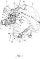
- FIGs. 1 and 2 there is shown an operator 5 using a night vision monocular 10.
- the monocular 10 is secured to a helmet 7 by use of a flip-up mount 20, which will be further described below.
- the monocular 10 has an objective lens 12, an eye piece 14 and a housing 16 between the objective lens and the eye piece.
- the operator 5 looks through the eye piece 14 and sees an enhanced image representative of the light which enters the objective lens 12.
- a night vision monocular 10 is shown, binocular systems are also widely used.
- the night vision monocular 10 secures to the flip-up mount 20 by interaction between a carriage 22 and a coupling device 18.
- the coupling device 18 comprises a trapezoidal plate which is secured to the housing 16 of the monocular 10.
- the plate 18 engages a plate receiving portion 24 of the carriage 22.
- an internal locking mechanism (not shown) secures the plate 18 in position.
- an eject button 32 is provided to remove the night vision monocular 10 and associated plate 18 from connection with the carriage 22. By manually depressing the eject button 32, the internal locking mechanism withdraws, allowing the plate 18 to be removed from engagement with the carriage 22.
- the position of the carriage 22 relative to the operator 5 is adjustable along rails 26.
- the rails 26 enable the night vision monocular 10 to be precisely positioned relative to the operator's eye, so as to optimize the system for each particular operator.
- Adjustment buttons 28 are provided which release the carriage from a normally secured position relative the rails 26 to enable the carriage 22 to be repositioned. Once a desired position has been obtained, the operator releases the adjustment buttons 28 and the carriage 22 locks into place.
- the flip-up mount 20 enables the operator 5 to manipulate the night vision monocular 10 between the operational position shown in Fig. 1, and the non-operational shown in Fig. 2.
- the monocular 10 is positioned relative the operator's eye so that the operator can normally view through the monocular.
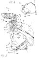
- the monocular 10 has been raised to the non-operational position so that both of the operator's eyes are unobstructed.
- the night vision monocular 10 will remain temporarily secured in the non-operational position until the operator chooses to return the monocular to the operational position.
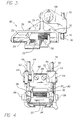
- the flip-up mount 20 is shown in greater detail in Figs. 3, 4 and 5.
- the flip-up mount 20 comprises an armature portion 30 which carries the carriage 22, and a support brace portion 70.
- the support brace 70 has a pivot axis about from which the armature 30 pivots, as will be further described below.
- the support brace portion 70 secures to the helmet 7 or a face mask 120, which will also be described below.
- the armature portion 30 comprises a back wall 35 and a carriage frame 38.
- the back wall 35 tapers to a top portion 34 which secures to the pivot axis, which will be described below.
- the carriage frame 38 secures to either end of each of the adjustment rails 26, providing a rigid support structure for the carriage 22.
- the carriage frame 38 extends generally perpendicular to the back wall 35.
- a support web 36 fills the generally triangular area formed by the intersection of the back wall 35 and the carriage frame 38, providing additional structural strength to the armature 30.
- the support brace portion 70 has a pair of outwardly extending support arms 68 which hold a shaft 62.
- the shaft 62 provides the pivot axis for the armature portion 30.
- the shaft 62 secures to the support brace 70 by end caps 64 disposed on either end of the shaft.
- a facing washer 56 is disposed around the shaft 62 at an end of the shaft adjacent to one of the support arms 68.
- the facing washer 56 has a finger 58 having tapered side surfaces.
- the top portion 34 of the back wall 35 secures to a pivot sleeve 42 disposed around the shaft 62.
- An end washer 44 forms one end of the pivot sleeve 42.
- the other end of the pivot sleeve 42 is formed by a notched washer 46.
- the notched washer 46 has a pair of notches 52, each of which is formed to receive the finger 58 described above.
- the notches 52 are disposed 180° apart relative the notched washer 46.
- a compression spring 54 is provided within the pivot sleeve 42. One end of the compression spring 54 presses against the end washer 46, to yieldably urge this washer 46 and sleeve 42 toward the facing washer 56.
- the compression force of the spring 54 maintains the pivot sleeve 42 generally pressed axially against the facing washer 56 with the finger 58 extending into the notch 52, effectively locking the armature 30 in place.
- the armature 30 To manipulate the armature 30 between the first and the second positions, the armature is moved so that the finger 58 leaves the first notch 52 against the normal bias of the spring 54. It will be apparent that because of the tapered side surfaces of the finger 58, the sleeve 42 moves axially to the left viewing Figure 4, or axially upwardly viewing Figure 5 (which is toward the right-hand side of the operator 5), along the shaft 62 in order to allow the sleeve 42 and armature 30 (along with night vision monocular 10) to pivot from the operative position as shown.
- the operator continues to rotate the armature 30 relative the support brace until the finger 58 reaches the second notch 52, whereupon the sleeve 42 is moved back toward the facing washer 56 by spring 54 and the finger 58 snaps into the second notch 52. In so doing, the operator can easily manipulate the armature between the two positions, and the armature will remain in the selected position by interaction between the finger 58 and the selected notch 52.
- the support brace 70 has a pair of spaced apart bore holes 74 that are generally joined by a bridge portion 72. Each of the bore holes 74 is intended to receive one of a pair of vertical anchor rods 78 which secure to the helmet 7.
- the vertical anchor rods extend along the surface of the helmet and are joined to a horizontal anchor rod 76.
- the lower end of the vertical anchor rod 78 holds a forward helmet hook 82 which has a curved lip portion 84.
- the lip portion 84 engages around the visor 9 of the helmet.
- the horizontal anchor rod 76 receives a pair of top straps 86 to rigidly hold the rods 76 and 78 in place.
- the top straps 86 join to a centre strap 88 which has a ratchet mechanism, shown generally at 90, which allows the flip-up mount to be used with large, medium or small helmets.
- the ratchet mechanism 90 has a corrugated portion 92 having a plurality of ridges. The ridges interact with a size adjuster 94 to vary the length of the centre strap 88. By pressing on the tab portion 93 of the adjustor 94, the adjustor comes out of engagement with the corrugated portion 92, allowing the corrugated portion to be either tightened or loosened, as desired.
- a ratchet release 96 is also provided to clamp the strap onto the helmet 7.
- a rear strap 102 Extending from the corrugated portion, is a rear strap 102, which terminates with a rear hook 104.
- the rear hook 104 engages the back edge of the helmet 7.
- a supplemental chin strap is provided.
- the standard issue helmet used by United States forces employs a chin strap which secures to the helmet at two places.
- the standard chin strap secures to two points adjacent the operator's ear on the helmet 7 and wraps under the operator's chin to the opposite side of the helmet.
- the additional weight of the system may cause the helmet 7 to drop forward relative the operator's face. This tends to set the system out of alignment with the operator's eye, and further causes the helmet to be uncomfortable to the operator.
- a supplemental chin strap 140 can be incorporated.
- the supplemental chin strap 140 completely replaces the standard chin strap which is provided with the helmet 7 with a first chin strap 144 and a second chin strap 142.
- the first chin strap 144 comprises a continuation of the rear strap 102, wrapping around the operator's neck and finally securing at the rear hook 104.
- the second chin strap 142 crosses and connects to the first chin strap 144 at a button 146. This 3-point supplemental chin strap maintains the helmet 7 in the proper position when the night vision system 10 is moved to the operational position.
- the face mask 120 comprises a curved rod 122 which partially surrounds the operator's face.
- the curved rod 122 has a plurality of cushion plates 124 evenly spaced around the operator's face.
- a sponge rubber pad 126 secures to the cushion plates so as to provide a comfortable fit for the operator.
- a top strap 128 extends from a center portion of the rod 122, which goes over the top of the operator's head and attaches to a skull cap 134 which engages the back of the operator's head.
- Side straps 132 similarly combine the rod 122 with the skull cap 134.
- a chin strap 136 extends from the back of the skull cap 134 to attach around the operator's chin.
- extension rods 118 Extending upward from a center portion of the rod 122 are a pair of spaced apart extension rods 118.
- the extension rods are spaced similar to the vertical anchor rod 78 described above.
- the extension bars 118 extend through the bore holes 74 of the support brace 70, securing the support brace to the face mask 120. It should be apparent that operation of the flip-up mount 20 in conjunction with the face mask 120 would be substantially identical to that described above when used in conjunction with the helmet mount.
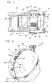
- the flip-up mount 20 be used in conjunction with a variety of types of night vision systems. Both night vision binoculars and monoculars are anticipated, as well as systems utilizing plate type mounting connectors or plug type mounting connectors.
- Figs. 1-7 show the use of the flip-up mount in conjunction with a plate type connector.
- Fig. 8 shows the flip-up mount 20 used in conjunction with a helmet 7 and a plug type connector. It is further anticipated that the adapter disclosed in US-A-5339464 can be used in conjunction with the face mask of Fig. 7 to enable the AN/PVS-7B night vision goggle.
Landscapes
- Physics & Mathematics (AREA)
- Astronomy & Astrophysics (AREA)
- General Physics & Mathematics (AREA)
- Optics & Photonics (AREA)
- Helmets And Other Head Coverings (AREA)
- Prostheses (AREA)
- Details Of Audible-Bandwidth Transducers (AREA)
- Walking Sticks, Umbrellas, And Fans (AREA)
Claims (27)
- Befestigung (20) für ein Nachtsichtsystem, wobei die Befestigung einen Schlitten (22) enthält, der so aufgebaut ist, daß er in ein Verbindungsstück (18) eingreift, das auf dem Nachtsichtsystem (10) bereitgestellt ist und das System daran befestigt, und einen Schwenkbeschlag (30), der den Schlitten (22) trägt und von einer Schwenkachse ausgeht, und der Beschlag (30) schwenkbar ist zwischen einer ersten Betriebsstellung, in der die Bedienperson das System verwenden kann, und einer zweiten Ruhestellung, und eine Strebe (70) vorhanden ist, die eine Vorrichtung (74) zum Befestigen der Strebe an einer Kopfbedeckung (7; 134) enthält, die die Bedienperson trägt, dadurch gekennzeichnet, daß die Strebe (70) einen Achsschaft (62) aufweist, der die Schwenkachse bestimmt, eine Hülse (42), die den Beschlag (30) trägt und um den Schaft drehbar ist, und eine federbelastete Einrastvorrichtung (52, 54, 58) zum wahlweisen Befestigen der Hülse entweder in der ersten oder in der zweiten Stellung.
- Befestigung nach Anspruch 1, wobei die Hülse (42) ein Teil mit dem Beschlag (30) bildet.
- Befestigung nach irgendeinem der vorhergehenden Ansprüche, wobei die Hülse (42) so eingerichtet ist, daß sie sich relativ zum Schaft (62) bewegt und eine erste axiale Position einnimmt, in der der Beschlag (30) gegen Schwenken gesichert ist, wenn er sich in der Betriebsstellung bzw. der Ruhestellung befindet, und eine zweite axiale Position zum Schwenken des Beschlags (30) zwischen der Betriebsstellung und der Ruhestellung.
- Befestigung nach Anspruch 1, 2 oder 3, wobei die Hülse axial entlang des Schafts beweglich ist und die Einrastvorrichtung ein Einrastglied (58) enthält und ein Federglied (54), das die Hülse (42) für den axialen Eingriff mit dem Einrastglied (58) vorspannt.
- Befestigung nach Anspruch 3 und 4, wobei das Federglied (54) so eingerichtet ist, daß es die Hülse (42) in die erste axiale Position drückt.
- Befestigung nach Anspruch 4 oder 5, wobei das Federglied (54) eine Feder enthält, die innerhalb der Hülse (42) montiert ist.
- Befestigung nach Anspruch 6, wobei die Feder eine Schraubendruckfeder ist.
- Befestigung nach Anspruch 4, 5, 6 oder 7, wobei die Einrastvorrichtung einen Finger (58) umfasst, der sich in axialer Richtung erstreckt und relativ zu einem der beiden Teile - der Strebe (70) oder der Hülse (42) - fest ist, und der Finger (58) allgemein abgeschrägte Kanten hat, und das andere der beiden Teile - die Hülse (42) oder die Strebe (70) - eine in axiale Richtung zeigende Passfläche aufweist, die dem Finger (58) gegenüberliegt, und ein Paar Kerben (52), die sich in die Passfläche erstrecken, wobei die Federvorrichtung (54) den Finger (58) normalerweise in direkte Berührung mit der Passfläche vorspannt, und die Kerben (52) mit einem Zwischenwinkel angeordnet sind, so daß die Hülse (42) relativ zum Schaft (62) drehbar ist, bis der Finger (58) in eine ausgewählte Kerbe (52) eingreift und den Beschlag (30) in seiner Stellung relativ zur Schwenkachse befestigt.
- Befestigung nach Anspruch 8, worin die erste axiale Position eingenommen wird, wenn der Finger (58) in eine der Kerben (52) eingreift, und die zweite axiale Position, wenn der Finger (58) die Passfläche berührt und nicht in eine der Kerben (52) eingreift.
- Befestigung nach Anspruch 8 oder 9, wobei die Hülse (42) das Kerbenpaar (52) aufweist.
- Befestigung nach Anspruch 10, wobei der Finger (58) von der Hülse (42) ausgeht und sich die Kerben (52) in eine Fläche erstrecken, die relativ zur Strebe (70) fest ist.
- Befestigung nach irgendeinem der Ansprüche 8 bis 11, wobei die Kerben (52) mit 180° Abstand um die Achse herum angeordnet sind.
- Befestigung nach irgendeinem der vorhergehenden Ansprüche, wobei der Schlitten (22) verschiebbar aufgebaut ist, damit er die Verbindungsvorrichtung eines Nachtsichtsystems eingreifend aufnimmt und tragend verbindet.
- Befestigung nach irgendeinem der vorhergehenden Ansprüche, zudem umfassend eine Verankerung, die Vorrichtungen (76, 78; 122) zum Befestigen der Strebenbefestigungseinrichtung (74) an einer Kopfbedeckung (7; 134) aufweist.
- Befestigung nach Anspruch 14, worin die Verankerung umfasst:eine normalerweise waagrechte Haltestange (76) und ein Paar Schlittenhaltestangen (78), die senkrecht zur normalerweise waagrechten Haltestange verlaufen, wobei die Schlittenhaltestangen die Verbindung zur Strebe herstellen;einen vorderen Haken (82), der an den Schlittenhaltestangen befestigt ist und zum Einhaken an einer Vorderkante eines Helms bestimmt ist, der als Kopfbedeckung dient; undeinen Riemen (86), der an der normalerweise waagrechten Haltestange angebracht ist und dem Befestigen an der rückwärtigen Helmkante dient.
- Befestigung nach Anspruch 15, ferner umfassend eine Rasteneinrichtung (92, 93) zum Ändern der Länge des Riemens (86).
- Befestigung nach irgendeinem der Ansprüche 1 bis 13, weiterhin umfassend eine Gesichtsmaske (134) als Kopfbedeckung, die die Bedienperson trägt, wobei die Strebe (70) an der Gesichtsmaske befestigt ist.
- Befestigung nach irgendeinem der Ansprüche 1 bis 16, auch umfassend einen Helm (7) als Kopfbedeckung, den die Bedienperson trägt, wobei die Strebe am Helm befestigt ist.
- Befestigung nach Anspruch 18, umfassend einen zusätzlichen Kinnriemen (144), der dem Befestigen an einem rückwärtigen Helmabschnitt dient, wobei der zusätzliche Kinnriemen den Helm in passender Stellung hält, wenn das System in der Betriebsstellung ist.
- Befestigung nach Anspruch 19, worin der Helm mit einem Kinnriemen versehen ist und der zusätzliche Kinnriemen so angepasst ist, daß er den Kinnriemen ersetzt, mit dem der Helm versehen ist.
- Befestigung nach Anspruch 19 oder 20, worin der zusätzliche Kinnriemen einen ersten Kinnriemen (144) enthält, der am rückwärtigen Abschnitt des Helms befestigt ist, und einen zweiten Kinnriemen (142), der an beiden Seiten des Helms befestigt ist, wobei der erste Kinnriemen und der zweite Kinnriemen an einem Schnittpunkt (146) zu beiden Seiten des Kinns der Bedienperson miteinander verbunden sind.
- Befestigung nach irgendeinem der vorhergehenden Ansprüche, wobei der Beschlag (30) ein Wandglied (35) aufweist, das von der Hülse (42) ausgeht und dort befestigt ist, um ein Paar beabstandete Schlittenrahmenglieder (38) zu bestimmen, die jeweils Schienen (26) tragen, an denen der Schlitten (22) verschiebbar befestigt ist, und eine von Hand zu betätigende Vorrichtung (28) vorhanden ist, die wahlweise den Schlitten (22) an den Schienen (26) befestigt bzw. davon löst.
- Befestigung nach Anspruch 23, zudem umfassend ein Paar Haltestege (36), die jeweils im Winkel zwischen einem entsprechenden Schlittenrahmenglied (38) und dem Wandglied (35) verlaufen.
- Befestigung nach irgendeinem der vorhergehenden Ansprüche, wobei der Schaft (62) zwischen einem Paar beabstandeter Arme (68) der Strebe (70) verläuft.
- Befestigung nach irgendeinem der vorhergehenden Ansprüche, wobei der Schlitten (22) einen Plattenaufnahmeabschnitt bestimmt, der so eingerichtet ist, daß er eine Schwalbenschwanz-Plattenbefestigung eines Nachtsichtsystems aufnimmt.
- Befestigung nach irgendeinem der vorhergehenden Ansprüche in Verbindung mit einem binokularen Nachtsichtsystem.
- Befestigung nach irgendeinem der Ansprüche 1 bis 25 in Verbindung mit einem monokularen Nachtsichtsystem.
Applications Claiming Priority (3)
| Application Number | Priority Date | Filing Date | Title |
|---|---|---|---|
| US91287592A | 1992-07-13 | 1992-07-13 | |
| US912875 | 1992-07-13 | ||
| PCT/US1993/006370 WO1994001011A1 (en) | 1992-07-13 | 1993-07-06 | Flip-up mount for night vision system |
Publications (3)
| Publication Number | Publication Date |
|---|---|
| EP0650604A1 EP0650604A1 (de) | 1995-05-03 |
| EP0650604A4 EP0650604A4 (de) | 1995-06-21 |
| EP0650604B1 true EP0650604B1 (de) | 1998-09-23 |
Family
ID=25432604
Family Applications (1)
| Application Number | Title | Priority Date | Filing Date |
|---|---|---|---|
| EP93916989A Expired - Lifetime EP0650604B1 (de) | 1992-07-13 | 1993-07-06 | Hochkippbare befestigung für ein nachtsichtsystem |
Country Status (8)
| Country | Link |
|---|---|
| US (1) | US5471678A (de) |
| EP (1) | EP0650604B1 (de) |
| KR (1) | KR970010404B1 (de) |
| AU (1) | AU666036B2 (de) |
| DE (1) | DE69321234T2 (de) |
| IL (1) | IL106013A (de) |
| SG (1) | SG43995A1 (de) |
| WO (1) | WO1994001011A1 (de) |
Cited By (26)
| Publication number | Priority date | Publication date | Assignee | Title |
|---|---|---|---|---|
| US7931683B2 (en) | 2007-07-27 | 2011-04-26 | Boston Scientific Scimed, Inc. | Articles having ceramic coated surfaces |
| US7938855B2 (en) | 2007-11-02 | 2011-05-10 | Boston Scientific Scimed, Inc. | Deformable underlayer for stent |
| US7942926B2 (en) | 2007-07-11 | 2011-05-17 | Boston Scientific Scimed, Inc. | Endoprosthesis coating |
| US7976915B2 (en) | 2007-05-23 | 2011-07-12 | Boston Scientific Scimed, Inc. | Endoprosthesis with select ceramic morphology |
| US7981150B2 (en) | 2006-11-09 | 2011-07-19 | Boston Scientific Scimed, Inc. | Endoprosthesis with coatings |
| US8002823B2 (en) | 2007-07-11 | 2011-08-23 | Boston Scientific Scimed, Inc. | Endoprosthesis coating |
| US8029554B2 (en) | 2007-11-02 | 2011-10-04 | Boston Scientific Scimed, Inc. | Stent with embedded material |
| US8067054B2 (en) | 2007-04-05 | 2011-11-29 | Boston Scientific Scimed, Inc. | Stents with ceramic drug reservoir layer and methods of making and using the same |
| US8066763B2 (en) | 1998-04-11 | 2011-11-29 | Boston Scientific Scimed, Inc. | Drug-releasing stent with ceramic-containing layer |
| US8071156B2 (en) | 2009-03-04 | 2011-12-06 | Boston Scientific Scimed, Inc. | Endoprostheses |
| US8187620B2 (en) | 2006-03-27 | 2012-05-29 | Boston Scientific Scimed, Inc. | Medical devices comprising a porous metal oxide or metal material and a polymer coating for delivering therapeutic agents |
| US8216632B2 (en) | 2007-11-02 | 2012-07-10 | Boston Scientific Scimed, Inc. | Endoprosthesis coating |
| US8221822B2 (en) | 2007-07-31 | 2012-07-17 | Boston Scientific Scimed, Inc. | Medical device coating by laser cladding |
| US8231980B2 (en) | 2008-12-03 | 2012-07-31 | Boston Scientific Scimed, Inc. | Medical implants including iridium oxide |
| US8287937B2 (en) | 2009-04-24 | 2012-10-16 | Boston Scientific Scimed, Inc. | Endoprosthese |
| US8353949B2 (en) | 2006-09-14 | 2013-01-15 | Boston Scientific Scimed, Inc. | Medical devices with drug-eluting coating |
| US8431149B2 (en) | 2007-03-01 | 2013-04-30 | Boston Scientific Scimed, Inc. | Coated medical devices for abluminal drug delivery |
| US8449603B2 (en) | 2008-06-18 | 2013-05-28 | Boston Scientific Scimed, Inc. | Endoprosthesis coating |
| US8574615B2 (en) | 2006-03-24 | 2013-11-05 | Boston Scientific Scimed, Inc. | Medical devices having nanoporous coatings for controlled therapeutic agent delivery |
| US8771343B2 (en) | 2006-06-29 | 2014-07-08 | Boston Scientific Scimed, Inc. | Medical devices with selective titanium oxide coatings |
| US8815273B2 (en) | 2007-07-27 | 2014-08-26 | Boston Scientific Scimed, Inc. | Drug eluting medical devices having porous layers |
| US8815275B2 (en) | 2006-06-28 | 2014-08-26 | Boston Scientific Scimed, Inc. | Coatings for medical devices comprising a therapeutic agent and a metallic material |
| US8900292B2 (en) | 2007-08-03 | 2014-12-02 | Boston Scientific Scimed, Inc. | Coating for medical device having increased surface area |
| US8920491B2 (en) | 2008-04-22 | 2014-12-30 | Boston Scientific Scimed, Inc. | Medical devices having a coating of inorganic material |
| US8932346B2 (en) | 2008-04-24 | 2015-01-13 | Boston Scientific Scimed, Inc. | Medical devices having inorganic particle layers |
| US9284409B2 (en) | 2007-07-19 | 2016-03-15 | Boston Scientific Scimed, Inc. | Endoprosthesis having a non-fouling surface |
Families Citing this family (80)
| Publication number | Priority date | Publication date | Assignee | Title |
|---|---|---|---|---|
| US5339464A (en) * | 1992-07-13 | 1994-08-23 | Litton Systems, Inc. | Universal adapter for night vision system |
| US5638544A (en) * | 1996-05-23 | 1997-06-17 | Ranger Joe's Columbus Army Surplus Co. | Military helmet with camouflage band retaining system and method for retaining a camouflage band on a military helmet |
| US5760953A (en) * | 1996-06-21 | 1998-06-02 | United States Of America As Represented By The Secretary Of The Air Force | Adaptor for night vision goggles |
| US5901369A (en) * | 1997-08-15 | 1999-05-11 | Honeywell Inc. | Headgear having an articulated mounting mechanism for a visor |
| US5914816A (en) * | 1997-11-04 | 1999-06-22 | Norotos, Inc. | Helmet mount for night vision goggle |
| GB9901978D0 (en) * | 1999-01-30 | 1999-03-17 | Isg Thermal Syst Ltd | Thermal imaging apparatus |
| US6141160A (en) * | 1999-03-17 | 2000-10-31 | International Technologies (Laser) Ltd. | Vision assist assembly for a single eye vision device |
| US6472776B1 (en) | 2000-03-30 | 2002-10-29 | Norotos, Inc. | Helmet mount for night vision device |
| US6457179B1 (en) | 2001-01-05 | 2002-10-01 | Norotos, Inc. | Helmet mount for night vision device |
| RU2189066C1 (ru) * | 2001-02-15 | 2002-09-10 | Государственное унитарное предприятие "Альфа" | Прибор ночного видения |
| US6909408B2 (en) * | 2001-12-20 | 2005-06-21 | Bendix Commercial Vehicle Systems Llc | Mounting assembly for night vision display unit |
| US6931668B2 (en) * | 2001-12-21 | 2005-08-23 | Itt Manufacturing Enterprises, Inc. | Headmount apparatus for attaching and supporting devices |
| US20040008157A1 (en) * | 2002-06-26 | 2004-01-15 | Brubaker Curtis M. | Cap-mounted monocular video/audio display |
| US6912727B2 (en) * | 2003-01-03 | 2005-07-05 | Itt Manufacturing Enterprises, Inc. | Head harness for night vision device |
| US6751810B1 (en) | 2003-03-13 | 2004-06-22 | Norotos, Inc. | Shroud plate |
| US6862748B2 (en) * | 2003-03-17 | 2005-03-08 | Norotos Inc | Magnet module for night vision goggles helmet mount |
| WO2004090580A2 (en) | 2003-04-04 | 2004-10-21 | Norotos, Inc. | Rotatable helmet mount |
| US8661571B1 (en) | 2003-10-06 | 2014-03-04 | Wilcox Industries Corp. | Helmet mounting systems |
| US7219370B1 (en) | 2003-10-06 | 2007-05-22 | Wilcox Industries Corp. | Helmet mounting systems |
| US20050111097A1 (en) * | 2003-11-26 | 2005-05-26 | Iannarelli Thomas M. | Head mounted binoculars/range finder |
| US7398562B2 (en) | 2004-03-10 | 2008-07-15 | Easy Rhino Designs, Inc. | Article with 3-dimensional secondary element |
| US6938276B1 (en) | 2004-04-07 | 2005-09-06 | Norotos, Inc. | Shroud plate attachment |
| US7484646B1 (en) * | 2004-09-23 | 2009-02-03 | The United States Of America As Represented By The Secretary Of The Navy | Dive mask index bracket |
| US7810168B2 (en) * | 2004-12-10 | 2010-10-12 | L-3 Insight Technology Incorporated | Method and apparatus for mounting a vision system |
| US7234173B2 (en) * | 2005-01-26 | 2007-06-26 | The Boeing Company | Helmet attachment apparatus and methods |
| US7418738B2 (en) * | 2005-02-04 | 2008-09-02 | Norotos, Inc. | Vertical adjustment mechanism for helmet mount for night vision device |
| US20070067894A1 (en) * | 2005-03-30 | 2007-03-29 | Litton Systems, Inc. | Mount for digitally enhanced night vision device |
| US7444683B2 (en) | 2005-04-04 | 2008-11-04 | Norotos, Inc. | Helmet mounting assembly with break away connection |
| US7996917B2 (en) | 2005-04-05 | 2011-08-16 | Norotos, Inc. | Rotatable helmet mounting assembly |
| US20070152406A1 (en) * | 2005-12-08 | 2007-07-05 | Prendergast Jonathon R | Width adjustable spring-loaded dovetail socket assembly |
| US7504918B2 (en) * | 2005-06-23 | 2009-03-17 | Norotos, Inc. | Magnetically activated switch |
| DE502005007327D1 (de) * | 2005-11-18 | 2009-07-02 | Vectronix Ag | Helmhalterung für ein Sichtgerät, insbesondere für ein Nachtsichtgerät |
| US8353066B2 (en) | 2006-02-04 | 2013-01-15 | Artisent, Llc | Easily adjusted retention system for helmets |
| US7600268B2 (en) * | 2006-02-04 | 2009-10-13 | Artisent, Inc. | Helmet retention system with improved stability |
| US7945967B2 (en) * | 2006-07-19 | 2011-05-24 | L-3 Insight Technology Incorporated | Method and apparatus for mounting a vision system |
| WO2009029907A2 (en) * | 2007-08-29 | 2009-03-05 | Revision Eyewear, Inc. | Attachment system for a helmet |
| US8209780B1 (en) * | 2007-10-25 | 2012-07-03 | Wilcox Industries Corp. | Pivoting helmet mount |
| WO2009059257A1 (en) * | 2007-11-02 | 2009-05-07 | Soto Ronald R | Universal mount for night vision goggles |
| US7722279B2 (en) * | 2007-11-26 | 2010-05-25 | Itt Manufacturing Enterprises, Inc. | Universal insert |
| US8181269B2 (en) * | 2007-11-26 | 2012-05-22 | Exelis, Inc. | Night vision goggle mount with retractable stops |
| US8087100B2 (en) * | 2007-11-26 | 2012-01-03 | Itt Manufacturing Enterprises, Inc. | Helmet mount for night vision goggles |
| US8239971B2 (en) | 2008-03-05 | 2012-08-14 | Norotos, Inc. | Carriage and socket assembly for a night vision goggle mount |
| US20100012692A1 (en) * | 2008-05-19 | 2010-01-21 | Bae Systems Aerospace & Defense Group Inc. | Helmet Attachment Platform |
| US20090313736A1 (en) * | 2008-06-18 | 2009-12-24 | Robert William Kocher | Varying thickness Helmet for reduced weight and increased protection |
| US8120857B2 (en) * | 2008-10-15 | 2012-02-21 | Gentex Corporation | Apparatus and method for mounting and calibrating a helmet-mounted display |
| US7969673B2 (en) * | 2008-11-11 | 2011-06-28 | Phokus Research Group, Llc | Night vision instrument focus device |
| US8127374B2 (en) * | 2009-01-16 | 2012-03-06 | Exelis, Inc. | Side positioned vision enhancement device mount |
| US9781963B1 (en) | 2009-04-13 | 2017-10-10 | Wilcox Industries Corp. | Helmet mount for viewing device |
| GB2539107B (en) * | 2009-06-01 | 2017-04-05 | Wilcox Ind Corp | Helmet mount for viewing device |
| US9848665B2 (en) * | 2009-09-03 | 2017-12-26 | Revision Military S.A.R.L. | Ballistic and impact protective system for military helmet assembly |
| US8739313B2 (en) | 2009-11-20 | 2014-06-03 | Wilcox Industries Corp. | Helmet mounting systems |
| US8984665B2 (en) | 2010-02-02 | 2015-03-24 | Wilcox Industries Corp. | Helmet mounting system and mounting shoe interface |
| USD692620S1 (en) | 2010-09-03 | 2013-10-29 | Revision Military S.A.R.L. | Helmet accessory mount |
| KR101291625B1 (ko) * | 2011-09-21 | 2013-08-01 | 연합정밀주식회사 | 개인 군용 부수물자를 부착가능한 군용 헬멧용 장착모듈 |
| US9116355B2 (en) | 2011-09-30 | 2015-08-25 | Wilcox Industries Corp. | Monocular/binocular bridge for viewing device and helmet mount employing same |
| WO2013192070A1 (en) | 2012-06-18 | 2013-12-27 | Gentex Corporation | Helmet cover assembly having at least one mounting device |
| US10051908B2 (en) * | 2012-06-28 | 2018-08-21 | Revision Military S.A.R.L. | Helmet-mounted display |
| US10162168B2 (en) | 2013-05-03 | 2018-12-25 | Wilcox Industries Corp. | Binocular bridge for thermal viewing device |
| US9709792B2 (en) | 2013-06-28 | 2017-07-18 | Wilcox Industries Corp. | Helmet mount with integral binocular bridge |
| USD721457S1 (en) * | 2014-05-16 | 2015-01-20 | Gentex Corporation | Mount arm |
| USD760442S1 (en) * | 2014-08-19 | 2016-06-28 | Christian G. Hill | Attachment for a helmet |
| EP3273818A4 (de) * | 2015-03-24 | 2019-01-02 | Gentex Corporation | Helmhaltesystem |
| USD810362S1 (en) | 2015-03-24 | 2018-02-13 | Gentex Corporation | Helmet retention system |
| US10455881B2 (en) * | 2015-04-21 | 2019-10-29 | Cadequip, Inc. | Adjustable headgear mount system |
| US9943127B2 (en) | 2015-11-30 | 2018-04-17 | Revision Military S.A.R.L. | Adjustable connector for a helmet accessory |
| US10415932B1 (en) | 2016-07-22 | 2019-09-17 | Knight Vision LLLP | Adjustable weapon-based mount for a monocular night-vision goggle |
| US20180192726A1 (en) * | 2017-01-10 | 2018-07-12 | Hmount Ltd | Plastic helmet mounting assembly |
| IL250044B (en) * | 2017-01-10 | 2019-05-30 | Shlomo Chen Itay | Plastic helmet adapter |
| CA3054449C (en) | 2017-03-13 | 2022-03-15 | Gentex Corporation | Helmet mounted shroud |
| WO2018169981A1 (en) * | 2017-03-13 | 2018-09-20 | Gentex Corporation | Modular shroud |
| TWI626899B (zh) * | 2017-06-14 | 2018-06-21 | Zhang le yan | 頭盔 |
| EP3649503B1 (de) * | 2017-07-07 | 2023-01-18 | BAE Systems PLC | Helmgestell zum verstauen und einstellen von kombinierer von hmd |
| AT521239B1 (de) | 2018-05-08 | 2020-02-15 | Leader Photonics Gmbh | Halterung zum Tragen eines Sensorsystems eines Feuerwehrhelms |
| US10937622B2 (en) * | 2018-12-19 | 2021-03-02 | Elbit Systems Of America, Llc | Programmable performance configurations for night vision device |
| USD969958S1 (en) * | 2019-01-17 | 2022-11-15 | Sheltered Wings, Inc. | Flip mount |
| US11327291B2 (en) | 2019-06-24 | 2022-05-10 | Elbit Systems Of America, Llc | Single actuation goggle positioning mounting assembly |
| US11402640B1 (en) * | 2019-08-15 | 2022-08-02 | Apple Inc. | Display adjustment for head-mountable device |
| US12155263B2 (en) | 2021-08-06 | 2024-11-26 | Galvion Ltd. | Helmet-mounted power system |
| EP4342380A1 (de) * | 2022-09-23 | 2024-03-27 | NIRx Medizintechnik GmbH | Kappenvorrichtung zur verwendung bei der erfassung von messdaten von einem kopf einer person |
| WO2025129078A1 (en) * | 2023-12-15 | 2025-06-19 | Maranon, Inc. | Headgear mount and imaging system |
Family Cites Families (6)
| Publication number | Priority date | Publication date | Assignee | Title |
|---|---|---|---|---|
| GB2167644B (en) * | 1984-02-15 | 1988-01-27 | Ms Instr Limited | Night vision goggle arrangement with automatic release |
| US4703879A (en) * | 1985-12-12 | 1987-11-03 | Varo, Inc. | Night vision goggle headgear |
| US4893356A (en) * | 1987-09-22 | 1990-01-16 | Waters William A | Air conditioned headwear having convertible power module |
| US4987608A (en) * | 1988-06-30 | 1991-01-29 | The United States Of America As Represented By The Secretary Of The Army | Mounting means for use of ground system type goggles as aviators goggle |
| US5077839A (en) * | 1990-08-06 | 1992-01-07 | Illinois Tool Works Inc. | Helmet chain strap buckle |
| US5331459A (en) * | 1991-12-10 | 1994-07-19 | Litton Systems, Inc. | Night vision system and mounting assembly |
-
1993
- 1993-06-14 IL IL10601393A patent/IL106013A/en not_active IP Right Cessation
- 1993-07-06 EP EP93916989A patent/EP0650604B1/de not_active Expired - Lifetime
- 1993-07-06 KR KR1019950700144A patent/KR970010404B1/ko not_active Expired - Fee Related
- 1993-07-06 SG SG1996008799A patent/SG43995A1/en unknown
- 1993-07-06 AU AU46657/93A patent/AU666036B2/en not_active Expired
- 1993-07-06 DE DE69321234T patent/DE69321234T2/de not_active Expired - Fee Related
- 1993-07-06 WO PCT/US1993/006370 patent/WO1994001011A1/en not_active Ceased
-
1994
- 1994-09-01 US US08/299,430 patent/US5471678A/en not_active Expired - Lifetime
Cited By (26)
| Publication number | Priority date | Publication date | Assignee | Title |
|---|---|---|---|---|
| US8066763B2 (en) | 1998-04-11 | 2011-11-29 | Boston Scientific Scimed, Inc. | Drug-releasing stent with ceramic-containing layer |
| US8574615B2 (en) | 2006-03-24 | 2013-11-05 | Boston Scientific Scimed, Inc. | Medical devices having nanoporous coatings for controlled therapeutic agent delivery |
| US8187620B2 (en) | 2006-03-27 | 2012-05-29 | Boston Scientific Scimed, Inc. | Medical devices comprising a porous metal oxide or metal material and a polymer coating for delivering therapeutic agents |
| US8815275B2 (en) | 2006-06-28 | 2014-08-26 | Boston Scientific Scimed, Inc. | Coatings for medical devices comprising a therapeutic agent and a metallic material |
| US8771343B2 (en) | 2006-06-29 | 2014-07-08 | Boston Scientific Scimed, Inc. | Medical devices with selective titanium oxide coatings |
| US8353949B2 (en) | 2006-09-14 | 2013-01-15 | Boston Scientific Scimed, Inc. | Medical devices with drug-eluting coating |
| US7981150B2 (en) | 2006-11-09 | 2011-07-19 | Boston Scientific Scimed, Inc. | Endoprosthesis with coatings |
| US8431149B2 (en) | 2007-03-01 | 2013-04-30 | Boston Scientific Scimed, Inc. | Coated medical devices for abluminal drug delivery |
| US8067054B2 (en) | 2007-04-05 | 2011-11-29 | Boston Scientific Scimed, Inc. | Stents with ceramic drug reservoir layer and methods of making and using the same |
| US7976915B2 (en) | 2007-05-23 | 2011-07-12 | Boston Scientific Scimed, Inc. | Endoprosthesis with select ceramic morphology |
| US8002823B2 (en) | 2007-07-11 | 2011-08-23 | Boston Scientific Scimed, Inc. | Endoprosthesis coating |
| US7942926B2 (en) | 2007-07-11 | 2011-05-17 | Boston Scientific Scimed, Inc. | Endoprosthesis coating |
| US9284409B2 (en) | 2007-07-19 | 2016-03-15 | Boston Scientific Scimed, Inc. | Endoprosthesis having a non-fouling surface |
| US8815273B2 (en) | 2007-07-27 | 2014-08-26 | Boston Scientific Scimed, Inc. | Drug eluting medical devices having porous layers |
| US7931683B2 (en) | 2007-07-27 | 2011-04-26 | Boston Scientific Scimed, Inc. | Articles having ceramic coated surfaces |
| US8221822B2 (en) | 2007-07-31 | 2012-07-17 | Boston Scientific Scimed, Inc. | Medical device coating by laser cladding |
| US8900292B2 (en) | 2007-08-03 | 2014-12-02 | Boston Scientific Scimed, Inc. | Coating for medical device having increased surface area |
| US8216632B2 (en) | 2007-11-02 | 2012-07-10 | Boston Scientific Scimed, Inc. | Endoprosthesis coating |
| US8029554B2 (en) | 2007-11-02 | 2011-10-04 | Boston Scientific Scimed, Inc. | Stent with embedded material |
| US7938855B2 (en) | 2007-11-02 | 2011-05-10 | Boston Scientific Scimed, Inc. | Deformable underlayer for stent |
| US8920491B2 (en) | 2008-04-22 | 2014-12-30 | Boston Scientific Scimed, Inc. | Medical devices having a coating of inorganic material |
| US8932346B2 (en) | 2008-04-24 | 2015-01-13 | Boston Scientific Scimed, Inc. | Medical devices having inorganic particle layers |
| US8449603B2 (en) | 2008-06-18 | 2013-05-28 | Boston Scientific Scimed, Inc. | Endoprosthesis coating |
| US8231980B2 (en) | 2008-12-03 | 2012-07-31 | Boston Scientific Scimed, Inc. | Medical implants including iridium oxide |
| US8071156B2 (en) | 2009-03-04 | 2011-12-06 | Boston Scientific Scimed, Inc. | Endoprostheses |
| US8287937B2 (en) | 2009-04-24 | 2012-10-16 | Boston Scientific Scimed, Inc. | Endoprosthese |
Also Published As
| Publication number | Publication date |
|---|---|
| AU4665793A (en) | 1994-01-31 |
| DE69321234D1 (de) | 1998-10-29 |
| WO1994001011A1 (en) | 1994-01-20 |
| DE69321234T2 (de) | 1999-01-21 |
| IL106013A0 (en) | 1993-10-20 |
| KR950702392A (ko) | 1995-07-29 |
| SG43995A1 (en) | 1997-11-14 |
| KR970010404B1 (ko) | 1997-06-26 |
| US5471678A (en) | 1995-12-05 |
| EP0650604A1 (de) | 1995-05-03 |
| AU666036B2 (en) | 1996-01-25 |
| IL106013A (en) | 1994-12-29 |
| EP0650604A4 (de) | 1995-06-21 |
Similar Documents
| Publication | Publication Date | Title |
|---|---|---|
| EP0650604B1 (de) | Hochkippbare befestigung für ein nachtsichtsystem | |
| EP0655146B1 (de) | Universeller adapter für nachtsichtgeräte | |
| US5467479A (en) | Night vision goggle mount | |
| EP2299857B1 (de) | Helmzubehörplattform | |
| US4918752A (en) | Helmet with detachable front section | |
| EP1619535B1 (de) | Halte- und Justiermechanismus für ein System zur Verbesserung der Sicht | |
| US7800043B2 (en) | Night vision goggles with detachable or reattachable modular components | |
| US5914816A (en) | Helmet mount for night vision goggle | |
| US8431881B2 (en) | Night vision goggles with pellicle | |
| EP0664469B1 (de) | Nachtsichtvisier | |
| US6957449B2 (en) | Rotatable helmet mount | |
| US5786932A (en) | Vision assisting apparatus | |
| US6789273B2 (en) | Protective eyewear systems and methods | |
| US20090040296A1 (en) | Head mounted display assembly | |
| GB2267764A (en) | Dual mounting assembly for night vision system | |
| US20030110548A1 (en) | Welding helmet | |
| JPS6285008A (ja) | 保護ヘルメツト | |
| US20040156113A1 (en) | Head harness for night vision device | |
| US20070067894A1 (en) | Mount for digitally enhanced night vision device | |
| US6292953B1 (en) | Interchangeable latch system | |
| US5341512A (en) | Vision limiting device | |
| EP4276517B1 (de) | Am kopf oder am helm getragenes anzeigemodul | |
| US20210157084A1 (en) | Configurable monocular display mount | |
| WO2025230984A1 (en) | Display device mounting system with a rail | |
| JPH06281879A (ja) | 頭部装着型表示装置 |
Legal Events
| Date | Code | Title | Description |
|---|---|---|---|
| PUAI | Public reference made under article 153(3) epc to a published international application that has entered the european phase |
Free format text: ORIGINAL CODE: 0009012 |
|
| 17P | Request for examination filed |
Effective date: 19950207 |
|
| AK | Designated contracting states |
Kind code of ref document: A1 Designated state(s): DE DK FR GB IT |
|
| A4 | Supplementary search report drawn up and despatched | ||
| AK | Designated contracting states |
Kind code of ref document: A4 Designated state(s): DE DK FR GB IT |
|
| 17Q | First examination report despatched |
Effective date: 19970227 |
|
| GRAG | Despatch of communication of intention to grant |
Free format text: ORIGINAL CODE: EPIDOS AGRA |
|
| GRAG | Despatch of communication of intention to grant |
Free format text: ORIGINAL CODE: EPIDOS AGRA |
|
| GRAH | Despatch of communication of intention to grant a patent |
Free format text: ORIGINAL CODE: EPIDOS IGRA |
|
| GRAH | Despatch of communication of intention to grant a patent |
Free format text: ORIGINAL CODE: EPIDOS IGRA |
|
| RAP1 | Party data changed (applicant data changed or rights of an application transferred) |
Owner name: LITTON SYSTEMS, INC. |
|
| GRAA | (expected) grant |
Free format text: ORIGINAL CODE: 0009210 |
|
| AK | Designated contracting states |
Kind code of ref document: B1 Designated state(s): DE DK FR GB IT |
|
| REF | Corresponds to: |
Ref document number: 69321234 Country of ref document: DE Date of ref document: 19981029 |
|
| ET | Fr: translation filed | ||
| PG25 | Lapsed in a contracting state [announced via postgrant information from national office to epo] |
Ref country code: DK Free format text: LAPSE BECAUSE OF FAILURE TO SUBMIT A TRANSLATION OF THE DESCRIPTION OR TO PAY THE FEE WITHIN THE PRESCRIBED TIME-LIMIT Effective date: 19981223 |
|
| PLBE | No opposition filed within time limit |
Free format text: ORIGINAL CODE: 0009261 |
|
| STAA | Information on the status of an ep patent application or granted ep patent |
Free format text: STATUS: NO OPPOSITION FILED WITHIN TIME LIMIT |
|
| 26N | No opposition filed | ||
| REG | Reference to a national code |
Ref country code: GB Ref legal event code: IF02 |
|
| PGFP | Annual fee paid to national office [announced via postgrant information from national office to epo] |
Ref country code: FR Payment date: 20020619 Year of fee payment: 10 |
|
| PGFP | Annual fee paid to national office [announced via postgrant information from national office to epo] |
Ref country code: DE Payment date: 20020730 Year of fee payment: 10 |
|
| PG25 | Lapsed in a contracting state [announced via postgrant information from national office to epo] |
Ref country code: DE Free format text: LAPSE BECAUSE OF NON-PAYMENT OF DUE FEES Effective date: 20040203 |
|
| PG25 | Lapsed in a contracting state [announced via postgrant information from national office to epo] |
Ref country code: FR Free format text: LAPSE BECAUSE OF NON-PAYMENT OF DUE FEES Effective date: 20040331 |
|
| REG | Reference to a national code |
Ref country code: FR Ref legal event code: ST |
|
| PGFP | Annual fee paid to national office [announced via postgrant information from national office to epo] |
Ref country code: IT Payment date: 20060731 Year of fee payment: 14 |
|
| PG25 | Lapsed in a contracting state [announced via postgrant information from national office to epo] |
Ref country code: IT Free format text: LAPSE BECAUSE OF NON-PAYMENT OF DUE FEES Effective date: 20070706 |
|
| REG | Reference to a national code |
Ref country code: GB Ref legal event code: 732E Free format text: REGISTERED BETWEEN 20110414 AND 20110420 |
|
| PGFP | Annual fee paid to national office [announced via postgrant information from national office to epo] |
Ref country code: GB Payment date: 20120719 Year of fee payment: 20 |
|
| REG | Reference to a national code |
Ref country code: GB Ref legal event code: PE20 Expiry date: 20130705 |
|
| PG25 | Lapsed in a contracting state [announced via postgrant information from national office to epo] |
Ref country code: GB Free format text: LAPSE BECAUSE OF EXPIRATION OF PROTECTION Effective date: 20130705 |