EP0649999A1 - Steuerung einer Drehmomentwandler-Überbrückungskupplung eines automatischen Getriebes - Google Patents
Steuerung einer Drehmomentwandler-Überbrückungskupplung eines automatischen Getriebes Download PDFInfo
- Publication number
- EP0649999A1 EP0649999A1 EP94307347A EP94307347A EP0649999A1 EP 0649999 A1 EP0649999 A1 EP 0649999A1 EP 94307347 A EP94307347 A EP 94307347A EP 94307347 A EP94307347 A EP 94307347A EP 0649999 A1 EP0649999 A1 EP 0649999A1
- Authority
- EP
- European Patent Office
- Prior art keywords
- bypass clutch
- vehicle speed
- engine
- current
- torque
- Prior art date
- Legal status (The legal status is an assumption and is not a legal conclusion. Google has not performed a legal analysis and makes no representation as to the accuracy of the status listed.)
- Granted
Links
Images


Classifications
-
- F—MECHANICAL ENGINEERING; LIGHTING; HEATING; WEAPONS; BLASTING
- F16—ENGINEERING ELEMENTS AND UNITS; GENERAL MEASURES FOR PRODUCING AND MAINTAINING EFFECTIVE FUNCTIONING OF MACHINES OR INSTALLATIONS; THERMAL INSULATION IN GENERAL
- F16H—GEARING
- F16H61/00—Control functions within control units of change-speed- or reversing-gearings for conveying rotary motion ; Control of exclusively fluid gearing, friction gearing, gearings with endless flexible members or other particular types of gearing
- F16H61/14—Control of torque converter lock-up clutches
- F16H61/143—Control of torque converter lock-up clutches using electric control means
-
- Y—GENERAL TAGGING OF NEW TECHNOLOGICAL DEVELOPMENTS; GENERAL TAGGING OF CROSS-SECTIONAL TECHNOLOGIES SPANNING OVER SEVERAL SECTIONS OF THE IPC; TECHNICAL SUBJECTS COVERED BY FORMER USPC CROSS-REFERENCE ART COLLECTIONS [XRACs] AND DIGESTS
- Y10—TECHNICAL SUBJECTS COVERED BY FORMER USPC
- Y10S—TECHNICAL SUBJECTS COVERED BY FORMER USPC CROSS-REFERENCE ART COLLECTIONS [XRACs] AND DIGESTS
- Y10S477/00—Interrelated power delivery controls, including engine control
- Y10S477/904—Control signal is acceleration
- Y10S477/905—Acceleration of throttle signal
Definitions
- This invention relates to control of a torque converter bypass clutch in an automatic transmission. More particularly, the invention pertains to altering where torque converter bypass clutch engagements and releases are to occur according to a reference schedule, on the basis of variations in engine output torque.
- the electronic control system for an automatic transmission is provided with a gear shift schedule that defines conditions of current engine throttle position and vehicle speed at which each gear ratio change is to occur.
- a gear shift schedule that defines conditions of current engine throttle position and vehicle speed at which each gear ratio change is to occur.
- data located in look-up tables stored in electronic memory, relating vehicle speed and engine throttle position for each of the gear ratio changes, are used to produce a signal representing the desired gear ratio.
- a command signal is produced by the control to cause a change in state of solenoid-operated shift valves. This changes the state of the planetary gear units and causes the gear ratio to change.
- a reference schedule of gear shift boundaries is continually referenced during execution of control algorithms and used to produce an upshift signal and a downshift signal when a boundary of the gear shift schedule is crossed.
- Gear shifts are made by continually probing computing memory with current values of throttle position and vehicle speed, and determining, on the basis of the stored shift schedules, whether an upshift or downshift is required. Upshift points are determined also on the basis of maximum engine speed when a wide-open throttle condition is detected.
- U.S. Patent 4,943,921 describes an electronic control for scheduling gear shifts in an automatic transmission on the basis of variations in ambient barometric pressure.
- Various functions relating vehicle speed and throttle position determine the occurrence of each upshift and downshift by probing computer memory, in which the gear shift functions reside, with current values of the throttle position and vehicle speed.
- a reference gear shift schedule is corrected for the difference between the operating barometric pressure and a reference barometric pressure, at which the gear shift schedules are calibrated, to automatically compensate for the effect of barometric pressure variations on the gear shift schedule.
- the method and system, according to this invention, for controlling the bypass clutch of an automatic transmission essentially alters the vehicle speed at which the torque converter bypass clutch locks/unlocks are to occur.
- the control compensates for changes in engine output torque from the engine torque at which a reference torque converter lock/unlock schedule is defined.
- the technique of the invention involves developing bypass clutch schedule at which acceptable gear ratio changes are to occur, the schedule being developed at reference magnitudes of engine output torque BTR BASE.
- the function for determining the magnitude of BTR BASE with reference to the current engine speed and throttle is stored in electronic memory accessible to a microprocessor.
- Current engine output torque TQ NET is calculated continually as is the ratio TQ NORM defined as TQ NET / BTR BASE.
- a vehicle equipped with an internal combustion engine controlled by a throttle and an automatic transmission is calibrated to determine a torque interpolation factor TQ INTR, engine speed adjustment and vehicle speed adjustment values that are combined arithmetically to modify the vehicle speed of the reference bypass clutch schedule.
- the torque interpolation factor defined as a function with reference to the range of engine throttle position, is accessible continually for use in producing control outputs. Also stored in electronic memory are vehicle speed adjustment values stored on the basis of engine throttle and the relevant gear ratio to which upshifts and downshifts are made. A term comprising the product of the torque interpolation factor multiplied by the vehicle speed adjustment is added algebraically to the corresponding vehicle speed defined by the reference bypass clutch schedule. The resulting vehicle speed compensates for a change of engine output torque from the torque at which the reference schedule is defined so that a desirable upshift or downshift occurs under current conditions.
- the result is a vehicle speed at which a desirable gear shift change occurs by compensating for engine output torque variations from the engine torque present when the reference bypass clutch lock/unlock schedule is defined.
- air and fuel are inducted by an internal combustion engine 10, which drives a shaft connecting the engine output and transmission input having the speed of the engine, NE, and the engine brake torque TQ-NET.
- Both the engine and transmission 11 are coupled to an electronic engine control module, which includes a microprocessor, input conditioning circuit, an electronic memory containing various algorithms for processing spark timing input, exhaust gas recirculation rate input, percent methonal fuel input, air/fuel ratio input, engine RPM input, engine air charge input, engine coolant temperature, firing cylinder indication input, engine operating hours, power steering pressure, timer input, air conditioning head pressure or air change temperature input, and a flag indicating whether the air conditioning compressor is on or off.
- engine operating parameters and other such parameters are described in U.S. Serial No.
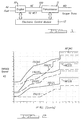
- Figure 2 shows gear ratio boundaries defined in terms of vehicle speed VS and throttle position TP REL.
- Throttle position corresponds to a signal produced by a throttle position sensor PRNDE indicating the amount of engine throttle displacement from a closed throttle or idle setting.
- Figure 2 shows where gear ratio changes, both upshifts and downshifts, are scheduled to occur automatically among the forward gear ratios produced by the transmission. Large values of TP REL occur near wide open throttle WOT, smaller values of TP REL indicate part throttle PT, and values near zero occur at nearly closed throttle positions CT.
- the data of Figure 2 are stored in read-only-memory ROM in the form of a look-up table.
- the lines marked FNXXS define boundaries where upshifts and downshifts occur according to the reference schedule of Figure 2, where XX represents the gear ratio change. At the right-hand end of the throttle position range near WOT, upshifts occur when engine speed has the values NEXXS.
- a signal indicating each commanded gear ratio GR CM is produced, according to the schedule of Figure 2, by a microprocessor using TP and VS as input. That signal causes a change in the state of solenoid-operated valves and a change of gear ratio to the commanded gear ratio.
- VS and TP REL change during vehicle operation in a particular gear ratio such that a line of Figure 2 is crossed during a background pass, during which engine and transmission control algorithms are executed, from an operating condition defined by these variables during the previous background pass, need for a gear shift is indicated by changing GM CM following a comparison of the desired gear ratio from Figure 2 and the current gear ratio.
- Gear shifts are made also on the basis of engine speed corresponding to a WOT condition above which an upshift is commanded regardless of the TP value.
- a 1-2 upshift occurs at engine speed NE12S, provided TP is equal to or greater than a predetermined wide open throttle TP.
- Each of the other upshift lines, 2-3 and 3-4, has a corresponding WOT shift point NE23S and NE34S.
- the WOT shift points are executed before shift points defined by the VS-TP relationship, as discussed below.
- Calibration constants are stored in ROM, accessible to the microprocessor, solely by reference to their memory addresses.
- Data stored in ROM or other electronic memory in the form of values of a first variable X, each X value having a single corresponding value of the second variable Y, recalled from memory by reference to a memory location and the first variable, are f(x) or "fox" functions.
- Data recalled from tables and fox functions are automatically interpolated to correspond to the values of the variables used to recall the data.
- a "register” is a variable whose value is calculated through execution of control algorithms.
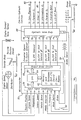
- the microprocessor 50 shown in Figure 3 is an integrated, central processor supplied with signals representing engine throttle position, engine speed, engine coolant temperature, torque converter speed, vehicle speed, a selected range of a gear selector, throttle valve pressure, the state of the selected transmission operating modes 52, the state of a brake switch 54, other input information mentioned above with reference to U.S. Serial No. 07/786,229, and signals representing the state of other operating parameters.
- Information conveyed by these input signals is conditioned by input conditioning circuitry 56 and transmitted on data bus 58 to a central processing unit 60 accessible to electronic memory 62.
- the electronic memory contains control algorithms for use in controlling gear shift scheduling, electronic pressure control EPC, and torque converter bypass clutch 82 operation.
- the central processing unit recalls information and control algorithms from electronic memory 62, executes the algorithms, and produces output signals carried on data bus 64 to output driver circuits 66, which produce electronic signals from the signals produced by the microprocessor.
- the output signals drive electrical solenoid-operated valves 70, 72, 74, 76, 78 located in an hydraulic valve body 68 adapted to respond to the output signals.
- the results of logical and arithmetic computations executed by the processor are stored in RAM, which is addressed, erased, rewritten, or changed in accordance with logic of the control algorithms.
- Data that are stored in memory include shift schedule information look-up tables, in which two variables, such as throttle position and vehicle speed, are mutually related and stored by reference to a particular gear ratio.
- Data stored in memory also includes functions, in which a first variable is used to select from memory corresponding variables and constants.
- control operation of the transmission are divided into several control modules executed sequentially in a known fashion during a background pass.
- the algorithms of each module are executed sequentially just as the modules themselves are executed sequentially.
- Information that results from the sensor input data and information stored in memory and learned from previous executions of background passes is used during execution of the control algorithms to produce electronic signals present at the output ports of the processor.
- Output signals drive on/off solenoid-operated shift valves 70, 72, 74, a variable force EPC solenoid 76, and a torque converter bypass clutch solenoid 78.
- Friction elements such as clutches 80, 82, brakes, and servos, are pressurised and vented through operation of solenoid-operated shift valves 70, 72, 74.
- the state of solenoids 70, 72, 74 change when a gear ratio change is commanded as a result of executing control algorithms, and the friction elements are engaged and released in accordance with the state of those solenoids.
- the lock-up clutch 82 of a torque converter 84 is alternately hard-locked or soft-locked (modulated) by directing hydraulic fluid through converter bypass-clutch control valve 86, which is supplied with regulated line pressure in line 88.
- a variable pressure valve 92 is supplied with constant pressure through line 94 from a solenoid-pressure regulator valve and is controlled by a pulse-width-modulated (PWM) signal applied to solenoid 78 from the microprocessor output.
- PWM pulse-width-modulated
- Valve 86 produces a pressure difference across bypass clutch 82.
- clutch 82 is hard-locked, a direct mechanical connection between impeller 96 and turbine 98 is produced.
- the impeller of torque converter 84 is driven from the crankshaft 100 of an engine, and turbine 98 drives a transmission input shaft 102.
- clutch 82 is disengaged, the turbine is driven hydrodynamically by the impeller.
- Figure 5 represents data from a look-up table stored in electronic memory relating vehicle speed and engine throttle position, each such table corresponding to a particular gear ratio.
- Line 110 represents the upper range of vehicle speed below which the torque converter 84 is unlocked by unlocking lockup clutch 82.
- line 110 carries the symbol FN2US.
- Line 112 defines the lower limit of vehicle speed over the range of engine throttle position, above which bypass clutch 82 is modulated or locked while the transmission is operating in the normal mode.
- line 112 is represented symbolically by FN2LS.
- This range represents a hysteresis zone in which the current state of bypass clutch 82 is maintained.
- Also stored in electronic memory is a table of expected engine torque output corresponding to the current engine speed NE and throttle position TP REL. This table is identified as BTR BASE in Figure 7.
- the table is populated with engine torque values BTR BASE at which the reference shift schedule of Figure 2 is established.
- the nominal conditions, such as a 20@ spark angle, and the engine torque output corresponding to those conditions, are the conditions and torque values at which the reference gear shift schedule, the schedule of Figure 2, is established.
- variable normalised torque output of the engine TQ NRM is defined as the ratio of TQ NET/BTR BASE. This normalised torque is the basis for changes to the standard shift schedule of Figure 2 that are made to compensate for variations in the expected torque output of the engine.
- TQ INTR The function shown in Figure 6, relating TQ INTR and TQ NORM, is also stored in electronic memory in the form of a look-up table.
- the value of TQ INTR is substantially zero, in a range of TQ NORM that straddles the value 1.0, rises above zero as TQ NORM increase above 1.0, and declines below zero when TQ NORM falls below the mid-range of TQ NORM values.
- the function relating TQ INTR and TQ NORM is determined by calibrating a vehicle equipped with an engine and automatic transmission such that desirable gear ratio changes are produced by altering the gear shift schedule of Figure 2 to compensate for changes in engine output torque.
- TQ INTR may equal 0.0 in the mid-range of TQ NORM values, i.e., in a narrow band on either side of 1.0.
- the function of Figure 6 is determined with the value of vehicle speed adjustment, engine speed adjustment, and converter bypass clutch vehicle speed adjustment, discussed below with reference to Figures 9, 10, and 12.
- TQ NET The control logic for scheduling gear ratio changes by controlling the states of shift solenoids 70, 72, 74 is described next with reference to Figure 8.
- the value of TQ NET is determined according to the method described in U.S. Serial No. 786,229, filed 10/13/91.
- BTR BASE is determined from the look-up table ( Figure 7) entered with engine speed NE and throttle position TP REL. If the base torque value from this table is zero, TQ NORM is set equal to 1.0; otherwise, TQ NORM is equal to TQ NET/BTR BASE. In either case, TQ INTR is equal to the value determined from the function of Figure 6 when the table is referenced with values of TQ NORM.
- control algorithms for producing upshifts and downshifts in accordance with the present invention by producing changes in the states of the solenoid-actuated shift valves 70, 72, 74, execute logic in the following order: first, a check is made to determine whether an upshift on the basis of engine speed is required; second, a check is made to determine whether an upshift based on vehicle speed is required; and third, a check is made to determine whether a downshift based on vehicle speed is required.
- the current commanded gear GR CM is compared to 1.0 in order to determine whether the first speed ratio is the desired speed ratio. If statement 120 is true, statement 122 is executed to determine whether filtered engine speed NE BART is greater than [NE12S + TQ INTR * NE12TQ] the sum of the engine speed of which an upshift from first gear to second gear would occur according to the reference gear shift schedule of Figure 2 and TQ INTR * NE12TQ.
- the constant NE12TQ is the engine speed adjustment value that compensates for engine output torque loss due to operation of the vehicle at conditions that differ from the conditions at which the reference gear shift schedule is determined.
- Engine speed is passed through a low pass filter implemented in software to reject high frequency speeds signals or noise.
- TQ INTR * NE12TQ corrects, compensates, or adjusts for variations in engine output torque from the torque at which the schedule of Figure 2 is determined.
- NE12TQ is a calibrated differential engine speed, for example, -300 rpm, such that when it is multiplied by TQ INTR and added to the engine speed of the reference shift schedule, the sum is lower than the reference schedule engine speed. Therefore, the shift occurs at a lower engine speed and compensates for a change of engine torque from the engine torque at which the reference shift schedule is established.
- a 3-2 downshift is produced by altering the state of the shift valves if the current vehicle speed is less than the engine torque compensated vehicle speed.
- Figures 9 and 10 show representatives of values of FNXXTQ and NEXXTQ, respectively, wherein "XX" represent 1-2, 2-3, and 3-4 upshifts, or 4-3, 3-2, or 2-1 downshifts.
- Figure 11 shows, schematically, the control logic that schedules locking and unlocking, i.e., application and release, of the torque converter bypass clutch 82 according to the present invention.
- the converter clutch control algorithm is entered at 188, and at 190 a check is made to determine whether the commanded gear is other than the first gear.
- VS LK FN[GR CM]LS + TQ INTR*FN[GR CM]LTQ
- VS UNLK FN[GR CM]US + TK-INTR * FN[GR CM]UTQ
- FN[GR CM]LS is the vehicle speed corresponding to the current commanded gear at which the torque converter bypass clutch is locked according to the reference schedule of Figure 5
- TQ INTR is the torque interpolation factor of Figure 6
- FN[GR CM]LTQ is the vehicle speed corresponding to the locked condition of the torque converter bypass clutch, determined by calibration and compensating for engine output torque reduction such that when it is multiplied by TQ INTR, and that product is added to the vehicle speed obtained from the schedule of Figure 4, an acceptable gear shift results.
- Figure 12 shows a function relating the variable FNXLTQ over the range of throttle position, which is stored in electronic memory, wherein X is a reference to the commanded gear ratio and L to the locked condition of clutch 82.
- X is a reference to the commanded gear ratio and L to the locked condition of clutch 82.
- a similar schedule of values for FNXUTQ is also stored in electronic memory and recalled as required from memory on the basis of the current operating throttle position.
- VSBART is compared to VS LK to determine whether current vehicle speed is greater than the torque compensated vehicle speed at which the torque converter clutch is to lock. If 194 is true, at 196, FLG CRV DS is set, thereby indicating the torque converter bypass clutch is to be locked. Control then passes to statement 202 where FLG CRV LK is set equal to 1.0 closing the output and driver circuit 66 to energise the converter bypass clutch solenoid 78 such that bypass clutch 82 is locked.
- FLG CRV DS is set equal to zero
- FLG CRV LK is also set equal to zero. This alternative resetting of FLG CRV LK goes to the output driver circuit 66 to apply a signal to bypass clutch solenoid 78 so that bypass clutch 82 is unlocked.
Landscapes
- Engineering & Computer Science (AREA)
- General Engineering & Computer Science (AREA)
- Mechanical Engineering (AREA)
- Control Of Transmission Device (AREA)
Applications Claiming Priority (2)
| Application Number | Priority Date | Filing Date | Title |
|---|---|---|---|
| US139690 | 1993-10-22 | ||
| US08/139,690 US5475590A (en) | 1993-10-22 | 1993-10-22 | Automatic transmission torque converter bypass clutch control using engine torque compensation |
Publications (2)
| Publication Number | Publication Date |
|---|---|
| EP0649999A1 true EP0649999A1 (de) | 1995-04-26 |
| EP0649999B1 EP0649999B1 (de) | 1998-05-06 |
Family
ID=22487860
Family Applications (1)
| Application Number | Title | Priority Date | Filing Date |
|---|---|---|---|
| EP94307347A Expired - Lifetime EP0649999B1 (de) | 1993-10-22 | 1994-10-06 | Steuerung einer Drehmomentwandler-Überbrückungskupplung eines automatischen Getriebes |
Country Status (3)
| Country | Link |
|---|---|
| US (1) | US5475590A (de) |
| EP (1) | EP0649999B1 (de) |
| DE (1) | DE69410056T2 (de) |
Cited By (1)
| Publication number | Priority date | Publication date | Assignee | Title |
|---|---|---|---|---|
| GB2353073A (en) * | 1999-05-26 | 2001-02-14 | Ford Global Tech Inc | Automatic Transmission ratio change schedules based on desired powertrain output |
Families Citing this family (11)
| Publication number | Priority date | Publication date | Assignee | Title |
|---|---|---|---|---|
| US5609552A (en) * | 1994-01-31 | 1997-03-11 | Nissan Motor Co., Ltd. | Lockup clutch control responsive to degraded ATF fluid condition |
| DE4417477A1 (de) * | 1994-05-19 | 1995-11-23 | Zahnradfabrik Friedrichshafen | Verfahren zum Steuern eines Automatgetriebes |
| US5553694A (en) * | 1994-10-14 | 1996-09-10 | Ford Motor Company | Multiple ratio automatic transmission and torque converter |
| JP3580993B2 (ja) * | 1997-10-01 | 2004-10-27 | 本田技研工業株式会社 | ロックアップ制御装置 |
| USH2031H1 (en) | 1998-12-21 | 2002-06-04 | Caterpillar Inc. | Apparatus and method for controlling the end of fill of a fluid actuated clutch |
| US6019703A (en) * | 1999-03-23 | 2000-02-01 | Daimlerchrysler Corporation | Transmission assembly for vehicle with torque converter clutch and method for engaging this clutch |
| US6506140B1 (en) * | 2000-09-26 | 2003-01-14 | Ford Global Technologies, Inc. | Control for vehicle with torque converter |
| US7084593B2 (en) | 2002-04-10 | 2006-08-01 | Visteon Global Technologies, Inc. | Method and apparatus for thermal management of an electric power assist steering control system by compensating steering motor current |
| US7917268B2 (en) * | 2007-04-16 | 2011-03-29 | Honda Motor Co., Ltd | Vehicle clutch engagement control system and method |
| US8224539B2 (en) * | 2007-11-02 | 2012-07-17 | GM Global Technology Operations LLC | Method for altitude-compensated transmission shift scheduling |
| US8437884B2 (en) * | 2010-07-28 | 2013-05-07 | GM Global Technology Operations LLC | System and method for detecting vehicle motion |
Citations (5)
| Publication number | Priority date | Publication date | Assignee | Title |
|---|---|---|---|---|
| US4335428A (en) * | 1979-02-14 | 1982-06-15 | Aisin-Waker Kabushiki Kaisha | Electronic system for controlling an automatic transmission in response to changes in slope |
| US4393467A (en) * | 1979-09-01 | 1983-07-12 | Aisin-Warner Kabushiki Kaisha | Lockup controlling system for variable speed, automatic transmission |
| EP0366284A1 (de) * | 1988-10-24 | 1990-05-02 | Ford Motor Company Limited | Steuerung einer Drehmomentenwandler-Direktkupplung eines automatischen Getriebes |
| DE4132104A1 (de) * | 1990-09-28 | 1992-04-09 | Fuji Heavy Ind Ltd | Steuerung eines automatischen getriebes fuer einen alkoholmotor |
| US5166879A (en) * | 1990-12-03 | 1992-11-24 | Ford Motor Company | Load condition preemption of scheduled gearshifts in an automatic transmission |
Family Cites Families (28)
| Publication number | Priority date | Publication date | Assignee | Title |
|---|---|---|---|---|
| DE2742031B2 (de) * | 1977-09-19 | 1979-09-13 | Robert Bosch Gmbh, 7000 Stuttgart | Gangwechseleinrichtung für Fahrzeug-Lastschaltgetriebe |
| JPS5830554A (ja) * | 1981-07-22 | 1983-02-23 | Toyota Motor Corp | 自動変速機の電子制御方法 |
| DE3470496D1 (en) * | 1983-06-01 | 1988-05-26 | Mazda Motor | Control means for vehicle automatic transmissions |
| JPS60121127A (ja) * | 1983-12-06 | 1985-06-28 | Nissan Motor Co Ltd | パワ−トレ−ンの制御方法 |
| DE3534971A1 (de) * | 1984-10-04 | 1986-04-10 | Zahnradfabrik Friedrichshafen Ag, 7990 Friedrichshafen | Steuereinrichtung zum selbsttaetigen schalten von stufenwechselgetrieben |
| US4665770A (en) * | 1985-03-18 | 1987-05-19 | Ford Motor Company | Control system for a multiple ratio transmission having a lockup clutch torque converter |
| JPS6226130A (ja) * | 1985-07-26 | 1987-02-04 | Toyota Motor Corp | 車両用自動変速機の変速制御方法 |
| JPS6280343A (ja) * | 1985-10-01 | 1987-04-13 | Toyota Motor Corp | 車輌用自動変速機の変速制御装置 |
| JPS62295732A (ja) * | 1986-06-16 | 1987-12-23 | Toyota Motor Corp | 自動変速機及びエンジンの一体制御装置 |
| JP2696819B2 (ja) * | 1986-10-08 | 1998-01-14 | 日産自動車株式会社 | 自動変速機の変速シヨツク軽減装置 |
| US4943921A (en) * | 1988-10-24 | 1990-07-24 | Ford Motor Company | Automatic transmission electronic gearshift control having altitude corrected shift criteria |
| JP2701429B2 (ja) * | 1989-03-03 | 1998-01-21 | 三菱電機株式会社 | 自動変速機の制御装置 |
| JPH0686188B2 (ja) * | 1989-04-04 | 1994-11-02 | 株式会社ユニシアジェックス | 運転状態認識装置及びこれを用いた自動変速機の変速制御装置 |
| DE3922051A1 (de) * | 1989-07-05 | 1991-01-24 | Porsche Ag | Verfahren und vorrichtung zur steuerung eines selbsttaetig schaltenden getriebes |
| US5029087A (en) * | 1989-07-24 | 1991-07-02 | Ford Motor Company | Electronic control system for controlling torque converter bypass clutches |
| JP2863932B2 (ja) * | 1989-09-30 | 1999-03-03 | スズキ株式会社 | 連続可変変速機制御装置 |
| US5107724A (en) * | 1989-12-14 | 1992-04-28 | Nissan Motor Co., Ltd. | Adaptive control for motor vehicle |
| FR2658647B1 (fr) * | 1990-02-21 | 1992-04-30 | Commissariat Energie Atomique | Tete magnetique horizontale a effet hall et son procede de realisation. |
| JPH03255261A (ja) * | 1990-03-05 | 1991-11-14 | Mazda Motor Corp | 自動変速機の制御装置 |
| JPH04113075A (ja) * | 1990-08-31 | 1992-04-14 | Isuzu Motors Ltd | 電子制御式変速機 |
| US5150297A (en) * | 1990-09-17 | 1992-09-22 | Ford Motor Company | Electronic shift controls for a multiple ratio transaxle |
| US5062321A (en) * | 1991-03-11 | 1991-11-05 | General Motors Corporation | Control apparatus for regulating engagement of a fluid operated torque transmitting device |
| US5086665A (en) * | 1991-06-27 | 1992-02-11 | Saturn Corporation | Adaptive shift pressure characterization of an electronically controlled automatic transmission |
| EP0529138B1 (de) * | 1991-08-30 | 1995-10-25 | Siemens Aktiengesellschaft | Steuerung für einen Kraftfahrzeugantrieb mit einem automatischen Getriebe |
| US5172609A (en) * | 1992-03-02 | 1992-12-22 | Saturn Corporation | Gradeability-based shift pattern control for an automatic transmission |
| US5303616A (en) * | 1992-08-10 | 1994-04-19 | Ford Motor Company | Electronically controlled bypass clutch based on percent-shift-completion for a torque converter |
| US5315901A (en) * | 1992-12-17 | 1994-05-31 | Ford Motor Company | Automatic transmission with a modulated pressure converter bypass clutch priority valve circuit |
| US5341703A (en) * | 1993-03-04 | 1994-08-30 | Ford Motor Company | Performance mode and economy mode shift scheduling in an automatic transmission |
-
1993
- 1993-10-22 US US08/139,690 patent/US5475590A/en not_active Expired - Lifetime
-
1994
- 1994-10-06 EP EP94307347A patent/EP0649999B1/de not_active Expired - Lifetime
- 1994-10-06 DE DE69410056T patent/DE69410056T2/de not_active Expired - Lifetime
Patent Citations (5)
| Publication number | Priority date | Publication date | Assignee | Title |
|---|---|---|---|---|
| US4335428A (en) * | 1979-02-14 | 1982-06-15 | Aisin-Waker Kabushiki Kaisha | Electronic system for controlling an automatic transmission in response to changes in slope |
| US4393467A (en) * | 1979-09-01 | 1983-07-12 | Aisin-Warner Kabushiki Kaisha | Lockup controlling system for variable speed, automatic transmission |
| EP0366284A1 (de) * | 1988-10-24 | 1990-05-02 | Ford Motor Company Limited | Steuerung einer Drehmomentenwandler-Direktkupplung eines automatischen Getriebes |
| DE4132104A1 (de) * | 1990-09-28 | 1992-04-09 | Fuji Heavy Ind Ltd | Steuerung eines automatischen getriebes fuer einen alkoholmotor |
| US5166879A (en) * | 1990-12-03 | 1992-11-24 | Ford Motor Company | Load condition preemption of scheduled gearshifts in an automatic transmission |
Cited By (2)
| Publication number | Priority date | Publication date | Assignee | Title |
|---|---|---|---|---|
| GB2353073A (en) * | 1999-05-26 | 2001-02-14 | Ford Global Tech Inc | Automatic Transmission ratio change schedules based on desired powertrain output |
| GB2353073B (en) * | 1999-05-26 | 2003-10-01 | Ford Global Tech Inc | Automatic transmission ratio change schedules based on a desired powertrain output |
Also Published As
| Publication number | Publication date |
|---|---|
| DE69410056T2 (de) | 1998-09-03 |
| DE69410056D1 (de) | 1998-06-10 |
| US5475590A (en) | 1995-12-12 |
| EP0649999B1 (de) | 1998-05-06 |
Similar Documents
| Publication | Publication Date | Title |
|---|---|---|
| EP0142046B1 (de) | Verfahren und Vorrichtung zur automatischen Steuerung der Fahrgeschwindigkeit mit dem Getriebe | |
| US6220987B1 (en) | Automatic transmission ratio change schedules based on desired powertrain output | |
| EP0816720B1 (de) | Schaltstabilisierungssteuerung für Automatikgetriebe | |
| US4584906A (en) | Gear shift control for an automatic transmission of a vehicle | |
| US5166879A (en) | Load condition preemption of scheduled gearshifts in an automatic transmission | |
| EP0636817B1 (de) | Fehlererkennungs-System und -Verfahren für automatische Getriebe | |
| EP0194799B1 (de) | Automatische Steuerung eines mechanischen Getriebes | |
| US5016175A (en) | Learned N/V ratio electronic control for automatic transmission reference speed in a driveline having unknown axle ratio | |
| EP1655520A1 (de) | Motormomentregelung, insbesondere beim Herunterschalten | |
| US6790160B2 (en) | Control device and control method for a vehicular automatic transmission | |
| EP0649999B1 (de) | Steuerung einer Drehmomentwandler-Überbrückungskupplung eines automatischen Getriebes | |
| US4819777A (en) | System for integrally controlling an engine and an automatic transmission having a device for determining engagement of the lockup clutch when a certain time duration elapses after output of an engagement signal | |
| US4967620A (en) | Line pressure control system for automotive automatic transmission having self-adjusting level control | |
| US4807497A (en) | System for integrally controlling automatic transmission and engine | |
| US5470288A (en) | Engine torque compensation shift scheduling of an automatic transmission for motor vehicles | |
| EP0614029A1 (de) | Steuerung der Schaltvorgänge in einem automatischen Getriebe | |
| US5117711A (en) | Control system for automotive automatic power transmission with fail-safe operation in response to failure of throttle angle sensor | |
| US5245893A (en) | Transmission detent shift control with acceleration-based compensation | |
| US5245541A (en) | System for and method of controlling automatic transmission | |
| US5163342A (en) | Adaptive transmission pressure control with run-through detection | |
| US6554742B2 (en) | Modification of shifting characteristics based upon shifting direction and drive train load | |
| US5484353A (en) | Method for reducing driveline disturbances by controlling torque converter clutch application | |
| KR100461616B1 (ko) | 차량의 변속제어장치 및 그 제어방법 | |
| US5233889A (en) | Control system for automotive automatic transmission | |
| EP0751028A2 (de) | Schaltdrehmomentsteuerung |
Legal Events
| Date | Code | Title | Description |
|---|---|---|---|
| PUAI | Public reference made under article 153(3) epc to a published international application that has entered the european phase |
Free format text: ORIGINAL CODE: 0009012 |
|
| AK | Designated contracting states |
Kind code of ref document: A1 Designated state(s): DE FR GB |
|
| 17P | Request for examination filed |
Effective date: 19950904 |
|
| 17Q | First examination report despatched |
Effective date: 19950929 |
|
| GRAG | Despatch of communication of intention to grant |
Free format text: ORIGINAL CODE: EPIDOS AGRA |
|
| GRAG | Despatch of communication of intention to grant |
Free format text: ORIGINAL CODE: EPIDOS AGRA |
|
| GRAH | Despatch of communication of intention to grant a patent |
Free format text: ORIGINAL CODE: EPIDOS IGRA |
|
| GRAH | Despatch of communication of intention to grant a patent |
Free format text: ORIGINAL CODE: EPIDOS IGRA |
|
| GRAA | (expected) grant |
Free format text: ORIGINAL CODE: 0009210 |
|
| AK | Designated contracting states |
Kind code of ref document: B1 Designated state(s): DE FR GB |
|
| PG25 | Lapsed in a contracting state [announced via postgrant information from national office to epo] |
Ref country code: FR Free format text: LAPSE BECAUSE OF FAILURE TO SUBMIT A TRANSLATION OF THE DESCRIPTION OR TO PAY THE FEE WITHIN THE PRESCRIBED TIME-LIMIT Effective date: 19980506 |
|
| REF | Corresponds to: |
Ref document number: 69410056 Country of ref document: DE Date of ref document: 19980610 |
|
| EN | Fr: translation not filed | ||
| PLBE | No opposition filed within time limit |
Free format text: ORIGINAL CODE: 0009261 |
|
| STAA | Information on the status of an ep patent application or granted ep patent |
Free format text: STATUS: NO OPPOSITION FILED WITHIN TIME LIMIT |
|
| 26N | No opposition filed | ||
| REG | Reference to a national code |
Ref country code: GB Ref legal event code: IF02 |
|
| PGFP | Annual fee paid to national office [announced via postgrant information from national office to epo] |
Ref country code: GB Payment date: 20130925 Year of fee payment: 20 |
|
| PGFP | Annual fee paid to national office [announced via postgrant information from national office to epo] |
Ref country code: DE Payment date: 20131031 Year of fee payment: 20 |
|
| REG | Reference to a national code |
Ref country code: DE Ref legal event code: R071 Ref document number: 69410056 Country of ref document: DE |
|
| REG | Reference to a national code |
Ref country code: GB Ref legal event code: PE20 Expiry date: 20141005 |
|
| PG25 | Lapsed in a contracting state [announced via postgrant information from national office to epo] |
Ref country code: GB Free format text: LAPSE BECAUSE OF EXPIRATION OF PROTECTION Effective date: 20141005 |