EP0648513B1 - Medical injection device - Google Patents
Medical injection device Download PDFInfo
- Publication number
- EP0648513B1 EP0648513B1 EP19940420277 EP94420277A EP0648513B1 EP 0648513 B1 EP0648513 B1 EP 0648513B1 EP 19940420277 EP19940420277 EP 19940420277 EP 94420277 A EP94420277 A EP 94420277A EP 0648513 B1 EP0648513 B1 EP 0648513B1
- Authority
- EP
- European Patent Office
- Prior art keywords
- liquid
- inlet
- outlet
- check valve
- upstream
- Prior art date
- Legal status (The legal status is an assumption and is not a legal conclusion. Google has not performed a legal analysis and makes no representation as to the accuracy of the status listed.)
- Expired - Lifetime
Links
- 238000010999 medical injection Methods 0.000 title description 2
- 239000007788 liquid Substances 0.000 claims description 91
- 238000011144 upstream manufacturing Methods 0.000 claims description 55
- 238000002347 injection Methods 0.000 claims description 37
- 239000007924 injection Substances 0.000 claims description 37
- 239000000463 material Substances 0.000 claims description 6
- 238000001990 intravenous administration Methods 0.000 claims description 3
- 239000012780 transparent material Substances 0.000 claims description 3
- 230000004913 activation Effects 0.000 claims 5
- 238000011109 contamination Methods 0.000 description 10
- 239000012530 fluid Substances 0.000 description 9
- 238000007789 sealing Methods 0.000 description 8
- 241000894006 Bacteria Species 0.000 description 3
- 208000031968 Cadaver Diseases 0.000 description 3
- 241000700605 Viruses Species 0.000 description 3
- 201000010099 disease Diseases 0.000 description 3
- 208000037265 diseases, disorders, signs and symptoms Diseases 0.000 description 3
- 239000007864 aqueous solution Substances 0.000 description 2
- 230000035515 penetration Effects 0.000 description 2
- 150000003384 small molecules Chemical class 0.000 description 2
- 208000030507 AIDS Diseases 0.000 description 1
- 102000015696 Interleukins Human genes 0.000 description 1
- 108010063738 Interleukins Proteins 0.000 description 1
- 244000052616 bacterial pathogen Species 0.000 description 1
- 230000005540 biological transmission Effects 0.000 description 1
- 239000008280 blood Substances 0.000 description 1
- 210000004369 blood Anatomy 0.000 description 1
- 238000005202 decontamination Methods 0.000 description 1
- 230000003588 decontaminative effect Effects 0.000 description 1
- 238000013461 design Methods 0.000 description 1
- 238000011161 development Methods 0.000 description 1
- 238000006073 displacement reaction Methods 0.000 description 1
- 230000000694 effects Effects 0.000 description 1
- 230000005489 elastic deformation Effects 0.000 description 1
- 230000005484 gravity Effects 0.000 description 1
- 208000015181 infectious disease Diseases 0.000 description 1
- 230000002458 infectious effect Effects 0.000 description 1
- 238000000034 method Methods 0.000 description 1
- 239000002991 molded plastic Substances 0.000 description 1
- 239000004033 plastic Substances 0.000 description 1
- 229920003023 plastic Polymers 0.000 description 1
- 238000012545 processing Methods 0.000 description 1
- 238000004064 recycling Methods 0.000 description 1
- 238000012360 testing method Methods 0.000 description 1
- 230000000007 visual effect Effects 0.000 description 1
- 238000003466 welding Methods 0.000 description 1
Images


Classifications
-
- A—HUMAN NECESSITIES
- A61—MEDICAL OR VETERINARY SCIENCE; HYGIENE
- A61M—DEVICES FOR INTRODUCING MEDIA INTO, OR ONTO, THE BODY; DEVICES FOR TRANSDUCING BODY MEDIA OR FOR TAKING MEDIA FROM THE BODY; DEVICES FOR PRODUCING OR ENDING SLEEP OR STUPOR
- A61M39/00—Tubes, tube connectors, tube couplings, valves, access sites or the like, specially adapted for medical use
- A61M39/22—Valves or arrangement of valves
- A61M39/24—Check- or non-return valves
- A61M2039/242—Check- or non-return valves designed to open when a predetermined pressure or flow rate has been reached, e.g. check valve actuated by fluid
-
- A—HUMAN NECESSITIES
- A61—MEDICAL OR VETERINARY SCIENCE; HYGIENE
- A61M—DEVICES FOR INTRODUCING MEDIA INTO, OR ONTO, THE BODY; DEVICES FOR TRANSDUCING BODY MEDIA OR FOR TAKING MEDIA FROM THE BODY; DEVICES FOR PRODUCING OR ENDING SLEEP OR STUPOR
- A61M39/00—Tubes, tube connectors, tube couplings, valves, access sites or the like, specially adapted for medical use
- A61M39/22—Valves or arrangement of valves
- A61M39/24—Check- or non-return valves
- A61M2039/2433—Valve comprising a resilient or deformable element, e.g. flap valve, deformable disc
- A61M2039/2446—Flexible disc
- A61M2039/2466—Flexible disc being fixed in its center
Definitions
- the present invention relates to devices for medical use allowing the injection of liquids into the human body.
- Liquid injections are usually done by means of an injection line such as a cathelon, a catheter, a needle hypodermic or intravenous.
- This injection pipe intended to penetrate in the human body, is connected to a syringe or a pipe liquid injection to inject the liquid from a reservoir.
- the problem proposed by the present invention is to design a new structure of a device for medical use for the injection of liquids which make it possible to avoid throwing after treatment of a patient the the entire injection device, while eliminating any risk of contamination between successive patients.
- the anti-contamination effectiveness of the device must be ensured both by authorizing high injection rates, i.e. flow rates of the order of 10 ml / s or more, and effectively opposing any transmission of infectious germs, even small ones, within usual conditions of use, especially in the absence of flow.
- the anti-contamination effectiveness of the device must be able to be easily checked during use in order to detect as soon as possible any faults and possible risks of contamination between successive patients.
- Another object of the invention is to facilitate the use of the injection device, avoiding the escape of fluids during disconnections, especially in devices with liquid source under pressure such as devices used in radiology.
- the device of the invention must also be compatible with an injection set that can be filled several times.
- the invention provides a device for medical use for the injection of liquids according to claim 1
- the removable connector itself constitutes a disposable element, which prevents all retrograde contamination, that is to say all passages of fluids, bacteria or viruses from the patient's body to the inlet nozzle allowing its connection to an outlet pipe of the liquid supply device. This ensures that the liquid supply device with its outlet pipe is not itself not contaminated, and that it can be used for several patients successive, provided that each time a new removable connector is fitted or decontaminated.
- the upstream and downstream tubular parts are made of a transparent material, revealing the appearance of liquid flowing through them.
- We can thus, by a simple visual control, ensure that there is no contamination upstream of the valve when a contamination is visible downstream of the valve, for example during a red or pink coloration in the presence of blood.
- the upstream tubular part is intended to contain a liquid under pressure. Liquid under pressure naturally tends to repel walls of the tubular parts, which can then contain liquid in excess. When disconnecting the removable connector, the natural elasticity the walls of the tubular parts flush out the excess liquid, which tends to flow outward. This results in an escape of one or several drops of liquid.
- a device for medical use for injecting liquids usually includes an injection line 1 such as a cathelon, catheter, hypodermic needle or intravenous, connected by means of conduction pipelines liquids 2 to a liquid supply device 3.
- the device liquid supply 3 is adapted to force the liquid under pressure in the means for conduction of liquids 2 and the injection pipe 1, for injecting the liquid into the body of a patient.
- the device for injecting liquids comprises a removable connector 4, inserted in the means of pipes of conduction of liquids 2 between the outlet pipe 5 of the device liquid supply 3 and the inlet 6 of the injection pipe 1.
- the removable connector 4 comprises a threshold non-return valve 7, adapted to prevent the flow of liquid from its outlet 13 towards its inlet 11, and adapted to allow the flow of liquid from its inlet 11 to its outlet 13 as illustrated by arrow 8 when the liquid pressure at its input exceeds the output pressure by a higher value or equal to a determined trigger threshold S.
- the removable connector 4 further comprises a tubular part upstream 9, a first end of which is provided with an inlet nozzle 10 adapted to allow its disconnectable connection to a outlet 5 of the liquid supply device 3, the second of which end is connected to inlet 11 of the threshold non-return valve 7.
- a simple upstream tube preferably with internal section generally constant over its entire length, connects the first and second ends upstream tubular part 9.
- the removable connector 4 also includes a tubular part downstream 12, a first end of which is connected to outlet 13 of the non-return valve with threshold 7, and the second end of which is provided with a outlet nozzle 14 suitable for direct disconnectable connection to the inlet of the injection pipe 1.
- a simple downstream tube preferably at interior section generally constant over its entire length, connects the first and second ends of downstream tubular part 12.
- the inlet nozzle 10 can be connected directly to the liquid supply device 3, or indirectly by the outlet pipe 5.
- the removable connector 4 may include inlet 10 and outlet 14 tips shaped and adapted to be removably connected to various pipes, the ends of which include similar end fittings.
- male end caps and end caps should be used females in such a way that we cannot reverse the input and the outlet of the removable connector 4, in order to respect the direction of propagation 8 some cash.
- the inlet nozzle 10 is a female end piece, while the outlet end piece 14 is a end piece male.
- the outlet nozzle 14 adapts to a conduit inlet 6 injection fitted with a corresponding female nozzle
- the inlet nozzle 10 adapts to a male connector provided at the outlet of the supply device in liquid 3 or at the outlet of the outlet pipe 5 which connects the liquid supply device 3 and the removable connector 4.
- the upstream tubular part 9 and the downstream tubular part 12 are preferably made of a transparent material, revealing the appearance of the liquid flowing through them.
- At least the downstream tubular part 12 is produced by a material giving it an adapted flexibility. Its length can advantageously be between 10 and 30 centimeters.
- the part upstream tubular 9 can also be flexible, to increase the possibilities of displacement and orientation of the injection pipe 1.
- the upstream tubular part 9 has a length reduced, for example between 1 and 4 centimeters approximately.
- this upstream tubular part can be made of a material relatively deformable, so that it can be flexible.
- the deformation of the wall of upstream tubular part 9 under the effect of the pressure of the liquid it contains causes a slight increase in his capacity.
- the wall of upstream tubular part 9 tends to regain its shape, driving out the excess liquid it contains and which flows outside.
- the upstream tubular part 9 must be short, as shown above.
- the trigger threshold S of the threshold non-return valve 7 is advantageously between 50 and 400 hecto Pascal. Thanks to such a threshold trigger, we make sure that no fluid, no bacteria, no virus cannot progress from the downstream tubular part 12 to the upstream tubular part 9, even when the supply device liquid 3 is at rest or when the upstream tubular part 9 is at a pressure lower than or equal to the pressure in the downstream tubular part 12. Passage through the threshold non-return valve 7 is only made when the pressure in the upstream tubular part 9 is significantly higher than the pressure in the downstream tubular part 12, so that the direction of progression of the liquid in the valve 7 is necessarily in accordance with the direction indicated by arrow 8, from upstream to downstream.
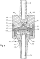
- FIG. 3 illustrates a first embodiment of the valve non-return threshold 7, made entirely of plastic.
- the valve as shown comprises a valve body 15 in two parts 40 and 41 holes in a through channel 16, the central part of which forms a shutter chamber 17.
- the shutter chamber 17 includes a seat intermediate 20 with sharp edge formed at the junction of an upstream portion 42 a smaller section sealing chamber and a downstream portion 43 of wider section sealing chamber.
- the shutter chamber 17 contains an elastically flexible transverse obturator disc 18 of which the periphery of the upstream face 19 is supported on the seat 20 with a sharp edge of the valve body 15 and whose downstream face 21 is axially constrained upstream by a central needle 22 of the valve body 15.
- the obturator disc 18 By elastic deformation under the action of needle 22, the obturator disc 18 is pressed against the seat 20. It is understood that the shutter disc 18 prohibits the passage of fluid from outlet 13 to inlet 11, because any excess fluid pressure in outlet 13 presses the obturator disc 18 against the seat 20. On the other hand, the shutter disc 18 authorizes the passage of fluid from inlet 11 to outlet 13 when the overpressure at inlet 11 is sufficient to elastically flex the periphery of the shutter disc 18 and to move it slightly away from the seat 20.
- the setting of the trigger threshold S is carried out by the choice appropriate thickness and hardness of the shutter disc 18.
- the body valve 15 is formed by the axial assembly of two parts, a part 40 forming the first upstream half of the valve body, a part 41 forming the second downstream half of the valve body.
- the two pieces 40 and 41 have annular ribs, as shown, shaped to fit into each other and create the room at the interface shutter 17.
- the assembly of parts 40 and 41 can, for example, be performed by ultrasonic welding, or by any other means.
- FIGS 4 and 5 illustrate the part 40 forming half upstream of the valve body.
- the through channel 16 comprises, at the entrance to the sealing chamber 17, a diametrical bridge 44 intended to cooperate with the obturator disc 18.
- the fluid can pass freely on either side of the diametrical bridge 44.
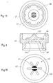
- FIGS 6 and 7 illustrate the part 41 constituting half downstream of the valve body.
- the needle 22 is a diametral rib generally flat with triangular longitudinal profile, as shown. Liquids can pass on either side of the rib forming the needle 22, from the sealing chamber 17 to the canal crossing 16.
- FIG. 8 illustrates, in longitudinal section, a second mode of preferred embodiment of a threshold check valve according to the present invention.
- a threshold check valve having a risk of passage less than 10 -5 .
- This risk of passage is measured according to the following test: downstream of the non-return valve, an aqueous solution of a product whose molecules are small in size is introduced, for example the product 3 H-2 deoxy-D-glucose, or the interleukin 6rH product. On the upstream side, an aqueous solution devoid of the small molecule product is introduced. The device is kept in this state for a determined period, for example 3 hours, at the end of which the quantity of small molecules which have been able to pass from the upstream side of the non-return valve is measured.
- FIG. 8 makes it possible to reduce the risk of passing to a value of less than 10 -5 , thus providing satisfactory safety for the usual applications of medical injections.
- the valve body 15 is produced by axial assembly of three parts 40, 41 and 45.
- Part 40 can advantageously be identical to the upstream part 40 of the embodiment of Figure 3.
- the part 41 may advantageously be identical downstream part 41 of the embodiment of FIG. 3.
- Part 45 is an intermediate part 45 inserted between the upstream part 40 and the part downstream 41.
- the intermediate piece 45 has an upstream face 46, also illustrated in FIG. 10, having the same shape as the upstream face of the downstream part 41, that is to say with a central needle 122 similar to the needle 22, in the shape of a diametrical rib, and with lateral passages 47 for the passage of liquid on either side of the rib forming the needle 122.
- the intermediate piece has a downstream face 48, also shown in Figure 11, shaped like the downstream face of the upstream part 40, that is to say with a similar intermediate seat 120 of the seat 20 of the upstream part 40.
- a first sealing chamber 17 is formed between the upstream part 40 and the intermediate part 45
- a second identical sealing chamber 117 is formed between the part intermediate 45 and the downstream part 41.
- the first sealing chamber 17 contains the first disc shutter 18, the periphery of the upstream face 19 is supported on the first intermediate seat 20 of the valve body 15, and whose downstream face 21 is axially constrained upstream by the central needle 122 of the intermediate part 45.
- the second sealing chamber 117 contains a second elastically transverse obturating disc 118 flexible whose periphery of the upstream face 119 is supported on the seat intermediate 120 of intermediate part 45 and whose downstream face 121 is constrained axially upstream by the central needle 22 of the downstream part 41 of the valve body 15.
- the shutter discs 18 and 118 perform a double filling.
- the threshold non-return valve 7, the part upstream tubular 9, downstream tubular part 12 and end pieces 10 and 14 can be made of molded plastics, the materials being chosen to comply with medical standards, to be compatible with the products to be injected and to be sterilizable by the usual methods.
- the liquid injection device comprises, upstream of the removable connector 4, an intermediate supply pipe 23 comprising a branch outlet 24 provided with a second non-return valve 25 with threshold, preventing the ascent of liquid from its outlet 26 to its inlet 27, and authorizing the passage of the liquid downstream when the pressure at the inlet 27 of the second non-return valve 25 exceeds the pressure at its outlet 26 according to a second determined trigger threshold S2.
- the output branch 24 advantageously comprises, downstream of the second non-return valve 25, a short pipe 28 of length less than about two centimeters. This avoids the flow of excess liquid when disconnecting the inlet nozzle 10.
- the intermediate supply line 23 includes in addition to an input branch 29 adapted to connect the input of the branch outlet 24 to outlet pipe 5 of a supply device in liquid 3 provided with means for generating overpressure and depression.
- the intermediate supply line 23 comprises also a filling branch 30 adapted to connect the inlet of the outlet branch 24 to a liquid reservoir 31, the branch of filling 30 being provided with a third non-return valve 32 at third low or zero S3 trigger threshold.
- the device for supplying liquid 3 generates an internal depression, causing a flow of liquid from the reservoir 31, through the third non-return valve 32 and the filling branch 30, and through the inlet branch 29 as far as the liquid supply device 3.
- the device for supplying liquid 3 pushes the liquid back under pressure through the inlet branch 29, the outlet branch 24, the second valve 25, the removable connector 4 and the injection line 1, when the pressure produced by the device liquid supply 3 is sufficient to force the liquid to through the two successive non-return valves 25 and 7.
- the second valve non-return 25 prevents the flow of liquid from the reservoir 31 to the output 26, provided that the second threshold S2 of the second valve 25 is higher than the liquid pressure resulting from the position raised tank 31.
- the liquid pressure inside the upstream tubular part 9 may be less than the pressure in the part downstream tubular 12, but the non-return valve 7 prevents any progression liquid, bacteria or virus from downstream to upstream, and prevents contamination of the upstream tubular part 9, of the nozzle input 10 and all the elements upstream.
- the disconnection of the inlet nozzle 10 is sufficient to isolate the fitting removable 4 and the injection pipe 1 relative to the other elements of the device that is not contaminated.
- the injection pipe 1 and the removable connector 4, which are possibly contaminated, are then discarded, or treated by recycling or decontamination.
- the second trigger threshold S2 of the second non-return valve with threshold 25 is less than the first threshold of triggering S of the first non-return valve 7 of the removable connector 4.
Description
La présente invention concerne les dispositifs à usage médical permettant l'injection de liquides dans le corps humain.The present invention relates to devices for medical use allowing the injection of liquids into the human body.
Les injections de liquides sont généralement effectuées au moyen d'un conduit d'injection tel qu'un cathelon, un cathéter, une aiguille hypodermique ou intraveineuse. Ce conduit d'injection, destiné à pénétrer dans le corps humain, est raccordé à une seringue ou à une canalisation d'injection de liquide pour injecter le liquide provenant d'un réservoir.Liquid injections are usually done by means of an injection line such as a cathelon, a catheter, a needle hypodermic or intravenous. This injection pipe, intended to penetrate in the human body, is connected to a syringe or a pipe liquid injection to inject the liquid from a reservoir.
On connaít notamment des dispositifs d'injection permettant l'injection sélective de plusieurs liquides à partir de plusieurs sources de liquides. Ces dispositifs sont notamment décrits dans les documents US-A-4 573 974, US-A-5 025 829, US-A-4 114 617, FR-A-2 119 367.We especially know injection devices for selective injection of several liquids from several sources liquids. These devices are described in particular in the documents US-A-4,573,974, US-A-5,025,829, US-A-4,114,617, FR-A-2,119,367.
Dans ces dispositifs, plusieurs canalisations comportant des
valves antiretour conduisent respectivement le liquide depuis l'une des
sources de liquide, et se rejoignent dans un raccord en Y prolongé par une
canalisation de sortie raccordée à un conduit d'injection. Les
canalisations conduisent les liquides unidirectionnellement depuis la
sortie des sources d'alimentation en liquide jusqu'à l'entrée du conduit
d'injection. Les sources d'alimentation en liquide sont le plus souvent
des récipients disposés en hauteur, l'écoulement du liquide se faisant par
gravité. Le document US-A-5 025 829 décrit des sources d'alimentation en
liquide sous pression, avec des pompes. Le plus souvent, des clapets de
contrôle de flux sont insérés dans les canalisations de conduction de
liquide, avec éventuellement des chambres de goutte-à-goutte. Certains
documents tels que le US-A-5 025 829, le US-A-4 114 617 et le
FR-A-2 119 367 décrivent des vannes antiretour comportant un seuil par
lequel la conduction de la valve nécessite une pression plus élevée à
l'entrée qu'en sortie.In these devices, several pipes comprising
non-return valves respectively carry the liquid from one of the
sources of liquid, and meet in a Y connector extended by a
outlet pipe connected to an injection pipe. The
pipes carry liquids unidirectionally from the
exit from liquid supply sources to entry of conduit
injection. Sources of liquid supply are most often
containers placed high up, the liquid flowing by
gravity. US-A-5,025,829 describes power sources for
liquid under pressure, with pumps. Most often, check valves
flow control are inserted into the conduction pipes of
liquid, possibly with drip chambers. Some
documents such as US-A-5,025,829, US-A-4,114,617 and the
FR-
Le but poursuivi dans ces documents est de contrôler les écoulements respectifs de liquide provenant des sources d'alimentation en liquide respectives. Les canalisations se raccordent directement aux sources d'alimentation en liquide, et il n'est pas prévu de moyens particuliers pour déconnecter une partie des canalisations de conduction de liquide.The purpose of these documents is to monitor the respective liquid flows from the supply sources respective liquid. The pipes are connected directly to the sources of liquid, and no means are provided individuals to disconnect part of the conduction pipes liquid.
Les documents US-A-2 538 662 et GB-A-2 000 685 décrivent des éléments de canalisation de conduction de liquide comportant une valve antiretour. Dans les deux cas, la valve antiretour nécessite un flux inverse de liquide pour assurer la fermeture, de sorte qu'une contamination rétrograde est possible.Documents US-A-2,538,662 and GB-A-2,000,685 describe liquid conduction pipe elements comprising a valve non-return. In both cases, the non-return valve requires a flow reverse liquid to ensure closure, so that a retrograde contamination is possible.
Dans tous ces dispositifs, aucun moyen n'est prévu pour permettre, dans des conditions de sécurité satisfaisantes, une utilisation du même dispositif pour plusieurs patients successifs.In all these devices, no means is provided for allow, under satisfactory safety conditions, use of the same device for several successive patients.
On sait que les fluides présents à l'intérieur du corps humain ont tendance à pénétrer également dans la seringue ou dans la canalisation, en l'absence de débit. Cette pénétration est d'autant plus accentuée lorsque les injections se poursuivent sur une durée longue, ou sont répétées au cours de cette durée, sans que le dispositif d'injection soit retiré.We know that the fluids present inside the human body tend to also enter the syringe or the pipeline, in the absence of flow. This penetration is all the more accentuated when the injections continue over a long period, or are repeated during this time, without the injection device be withdrawn.
Ainsi, la pénétration des fluides du corps humain à l'intérieur des canalisations tend à contaminer l'ensemble du dispositif d'injection de liquides.So the penetration of fluids from the human body inside pipes tend to contaminate the entire injection system liquids.
Le développement des maladies contagieuses, notamment du Sida, conduit ainsi à jeter la totalité du dispositif d'injection de liquides à la fin du traitement de chaque patient, pour éviter qu'un tel dispositif contaminé puisse lui-même contaminer ultérieurement un autre patient qui n'est pas atteint de la maladie. Il en résulte une diminution sensible de la durée d'usage des dispositifs d'injection de liquides, et une augmentation correspondante du coût de diagnostic ou de traitement des maladies.The development of contagious diseases, especially AIDS, thus leads to discarding the entire liquid injection device at the end of treatment for each patient, to prevent such a device contaminated could itself later contaminate another patient who does not have the disease. This results in a significant decrease in the duration of use of the liquid injection devices, and a corresponding increase in the cost of diagnosing or treating diseases.
Partant de l'état de la technique selon FR-A-2 119 367, le problème proposé par la présente invention est de concevoir une nouvelle structure de dispositif à usage médical pour l'injection de liquides qui permette d'éviter de jeter après traitement d'un patient la totalité du dispositif d'injection, tout en supprimant tout risque de contamination entre les patients successifs. On cherche ainsi à réutiliser le même dispositif de façon optimale pour plusieurs patients, pour minimiser les coûts de traitement.Starting from the state of the art according to FR-A-2 119 367, the problem proposed by the present invention is to design a new structure of a device for medical use for the injection of liquids which make it possible to avoid throwing after treatment of a patient the the entire injection device, while eliminating any risk of contamination between successive patients. We are looking to reuse the same device optimally for multiple patients, for minimize processing costs.
L'efficacité anti-contamination du dispositif doit être assurée à la fois en autorisant des forts débits d'injection, c'est-à-dire des débits de l'ordre de 10 ml/s ou plus, et en s'opposant efficacement à toute transmission de germes infectieux, même de petite taille, dans les conditions habituelles d'utilisation, surtout en l'absence de débit.The anti-contamination effectiveness of the device must be ensured both by authorizing high injection rates, i.e. flow rates of the order of 10 ml / s or more, and effectively opposing any transmission of infectious germs, even small ones, within usual conditions of use, especially in the absence of flow.
De préférence, l'efficacité anti-contamination du dispositif doit pouvoir être contrôlée aisément pendant l'utilisation, afin de détecter le plus tôt possible les éventuels défauts et les éventuels risques de contamination entre les patients successifs.Preferably, the anti-contamination effectiveness of the device must be able to be easily checked during use in order to detect as soon as possible any faults and possible risks of contamination between successive patients.
Un autre objet de l'invention est de faciliter l'utilisation du dispositif d'injection, en évitant la sortie de fluides lors des déconnexions, notamment dans les dispositifs à source de liquide sous pression tels que les dispositifs utilisés en radiologie.Another object of the invention is to facilitate the use of the injection device, avoiding the escape of fluids during disconnections, especially in devices with liquid source under pressure such as devices used in radiology.
Le dispositif de l'invention doit également être compatible avec un ensemble d'injection susceptible d'être rempli plusieurs fois.The device of the invention must also be compatible with an injection set that can be filled several times.
Pour atteindre ces objets ainsi que d'autres, l'invention prévoit un dispositif à usage médical pour l'injection de liquides selon la revendication 1To achieve these and other objects, the invention provides a device for medical use for the injection of liquids according to claim 1
Le raccord amovible constitue lui-même un élément jetable, qui empêche toutes contaminations rétrogrades, c'est-à-dire tous passages de fluides, de bactéries ou de virus depuis le corps du patient jusqu'à l'embout d'entrée permettant son raccordement à une canalisation de sortie du dispositif d'alimentation en liquide. Ainsi, on s'assure que le dispositif d'alimentation en liquide avec sa canalisation de sortie n'est lui-même pas contaminé, et qu'il peut servir pour plusieurs patients successifs, à condition d'adapter à chaque fois un raccord amovible neuf ou décontaminé.The removable connector itself constitutes a disposable element, which prevents all retrograde contamination, that is to say all passages of fluids, bacteria or viruses from the patient's body to the inlet nozzle allowing its connection to an outlet pipe of the liquid supply device. This ensures that the liquid supply device with its outlet pipe is not itself not contaminated, and that it can be used for several patients successive, provided that each time a new removable connector is fitted or decontaminated.
De préférence, les parties tubulaires amont et aval sont réalisées en un matériau transparent, laissant apparaítre l'aspect du liquide qui les traverse. On peut ainsi, par un simple contrôle visuel, s'assurer de l'absence de contamination en amont de la valve lorsqu'une contamination est visible en aval de la valve, par exemple lors d'une coloration rouge ou rosée en présence de sang.Preferably, the upstream and downstream tubular parts are made of a transparent material, revealing the appearance of liquid flowing through them. We can thus, by a simple visual control, ensure that there is no contamination upstream of the valve when a contamination is visible downstream of the valve, for example during a red or pink coloration in the presence of blood.
La partie tubulaire amont est destinée à contenir un liquide sous pression. Le liquide sous pression tend naturellement à repousser les parois des parties tubulaires, qui peuvent alors contenir du liquide en excès. Lors de la déconnexion du raccord amovible, l'élasticité naturelle des parois des parties tubulaires chasse l'excès de liquide, qui tend à s'écouler vers l'extérieur. Il en résulte un échappement d'une ou plusieurs gouttes de liquide.The upstream tubular part is intended to contain a liquid under pressure. Liquid under pressure naturally tends to repel walls of the tubular parts, which can then contain liquid in excess. When disconnecting the removable connector, the natural elasticity the walls of the tubular parts flush out the excess liquid, which tends to flow outward. This results in an escape of one or several drops of liquid.
Pour éviter cela, on peut soit utiliser une partie tubulaire amont rigide, soit prévoir qu'une telle partie tubulaire amont est la plus courte possible, par exemple d'une longueur comprise entre 1 et 4 centimètres environ.To avoid this, we can either use a tubular part rigid upstream, or provide that such an upstream tubular part is the most short possible, for example between 1 and 4 about centimeters.
D'autres objets, caractéristiques et avantages de la présente invention ressortiront de la description suivante de modes de réalisation particuliers, faite en relation avec les figures jointes, parmi lesquelles:
- la figure 1 est une vue schématique générale d'un dispositif d'injection de liquides à usage médical selon l'invention ;
- la figure 2 est une vue de face d'un raccord amovible selon un mode de réalisation de l'invention ;
- la figure 3 est une vue en coupe longitudinale d'un premier mode de réalisation de valve utilisable pour constituer le raccord de la figure 2 ;
- la figure 4 est une vue en coupe longitudinale d'une première pièce formant la moitié amont du corps de valve de la figure 3 ;
- la figure 5 est une vue en bout du côté aval de la pièce de la figure 4 ;
- la figure 6 est une coupe longitudinale d'une seconde pièce formant la moitié aval du corps de valve de la figure 3 ;
- la figure 7 est une vue du côté amont de la pièce de la figure 6 ;
- la figure 8 est une coupe longitudinale d'une valve antiretour à seuil selon un second mode de réalisation de la présente invention ;
- la figure 9 est une coupe longitudinale de la pièce centrale du corps de valve de la figure 8 ;
- la figure 10 est une vue en bout du côté aval de la pièce centrale de la figure 9 ; et
- la figure 11 est une vue en bout du côté amont de la pièce centrale de la figure 9.
- Figure 1 is a general schematic view of a liquid injection device for medical use according to the invention;
- Figure 2 is a front view of a removable connector according to an embodiment of the invention;
- Figure 3 is a longitudinal sectional view of a first embodiment of the valve usable to form the connector of Figure 2;
- Figure 4 is a longitudinal sectional view of a first part forming the upstream half of the valve body of Figure 3;
- Figure 5 is an end view of the downstream side of the part of Figure 4;
- Figure 6 is a longitudinal section of a second part forming the downstream half of the valve body of Figure 3;
- Figure 7 is a view from the upstream side of the part of Figure 6;
- Figure 8 is a longitudinal section of a threshold check valve according to a second embodiment of the present invention;
- Figure 9 is a longitudinal section of the central part of the valve body of Figure 8;
- Figure 10 is an end view of the downstream side of the central part of Figure 9; and
- FIG. 11 is an end view of the upstream side of the central part of FIG. 9.
Comme le représente la figure 1, un dispositif à usage médical
pour l'injection de liquides comprend généralement un conduit d'injection
1 tel qu'un cathelon, un cathéter, une aiguille hypodermique ou
intraveineuse, raccordé par des moyens de canalisations de conduction de
liquides 2 à un dispositif d'alimentation en liquide 3. Le dispositif
d'alimentation en liquide 3 est adapté pour forcer le liquide sous
pression dans les moyens de canalisations de conduction de liquides 2 et
le conduit d'injection 1, pour injecter le liquide dans le corps d'un
patient.As shown in Figure 1, a device for medical use
for injecting liquids usually includes an injection line
1 such as a cathelon, catheter, hypodermic needle or
intravenous, connected by means of
Selon l'invention, le dispositif d'injection de liquides
comprend un raccord amovible 4, inséré dans les moyens de canalisations de
conduction de liquides 2 entre la canalisation de sortie 5 du dispositif
d'alimentation en liquide 3 et l'entrée 6 du conduit d'injection 1. According to the invention, the device for injecting liquids
comprises a removable connector 4, inserted in the means of pipes of
conduction of
Le raccord amovible 4 comprend une valve antiretour à seuil 7,
adaptée pour interdire le flux de liquide de sa sortie 13 vers son entrée
11, et adaptée pour autoriser le flux de liquide de son entrée 11 vers sa
sortie 13 comme illustré par la flèche 8 lorsque la pression de liquide à
son entrée excède la pression en sortie selon une valeur supérieure ou
égale à un seuil de déclenchement déterminé S.The removable connector 4 comprises a threshold
Le raccord amovible 4 comprend en outre une partie tubulaire
amont 9, dont une première extrémité est munie d'un embout d'entrée 10
adapté pour permettre son raccordement déconnectable à une canalisation de
sortie 5 du dispositif d'alimentation en liquide 3, et dont la seconde
extrémité est raccordée à l'entrée 11 de la valve antiretour à seuil 7. Un
simple tube amont, de préférence à section intérieure généralement
constante sur toute sa longueur, relie les première et seconde extrémités
de partie tubulaire amont 9.The removable connector 4 further comprises a tubular part
upstream 9, a first end of which is provided with an
Le raccord amovible 4 comprend également une partie tubulaire
aval 12, dont une première extrémité est raccordée à la sortie 13 de la
valve antiretour à seuil 7, et dont la seconde extrémité est munie d'un
embout de sortie 14 adapté pour un raccordement déconnectable direct à
l'entrée du conduit d'injection 1. Un simple tube aval, de préférence à
section intérieure généralement constante sur toute sa longueur, relie les
première et seconde extrémités de partie tubulaire aval 12.The removable connector 4 also includes a tubular part
downstream 12, a first end of which is connected to
L'embout d'entrée 10 peut être raccordé directement au
dispositif d'alimentation en liquide 3, ou indirectement par la
canalisation de sortie 5.The
Comme illustré sur la figure 2, le raccord amovible 4 selon
l'invention peut comprendre des embouts d'entrée 10 et de sortie 14
conformés et adaptés pour se raccorder de façon amovible à diverses
canalisations dont les extrémités comprennent des embouts similaires. De
préférence, il convient d'utiliser des embouts mâles et des embouts
femelles de telle façon que l'on ne puisse pas inverser l'entrée et la
sortie du raccord amovible 4, afin de respecter le sens de propagation 8
du liquide. Dans l'exemple illustré sur la figure, l'embout d'entrée 10
est un embout femelle, tandis que l'embout de sortie 14 est en embout
mâle. Ainsi, l'embout de sortie 14 s'adapte à une entrée 6 de conduit
d'injection munie d'un embout femelle correspondant, et l'embout d'entrée
10 s'adapte à un embout mâle prévu en sortie du dispositif d'alimentation
en liquide 3 ou en sortie de la canalisation de sortie 5 qui raccorde le
dispositif d'alimentation en liquide 3 et le raccord amovible 4. On pourra
avantageusement utiliser des embouts répondant aux normes internationales
en usage dans le domaine médical.As illustrated in FIG. 2, the removable connector 4 according to
the invention may include
La partie tubulaire amont 9 et la partie tubulaire aval 12 sont
de préférence réalisées en un matériau transparent, laissant apparaítre
l'aspect du liquide qui les traverse.The upstream
Pour assurer une liberté de déplacement et d'orientation du
conduit d'injection 1, on réalise au moins la partie tubulaire aval 12 en
un matériau lui conférant une flexibilité adaptée. Sa longueur peut
avantageusement être comprise entre 10 et 30 centimètres. La partie
tubulaire amont 9 peut également être flexible, pour augmenter les
possibilités de déplacement et d'orientation du conduit d'injection 1.To ensure freedom of movement and orientation of the
injection pipe 1, at least the downstream
De préférence, la partie tubulaire amont 9 a une longueur
réduite, par exemple comprise entre 1 et 4 centimètres environ. Dans ce
cas, cette partie tubulaire amont peut être réalisée en un matériau
relativement déformable, de sorte qu'elle peut être flexible. La
déformation de la paroi de partie tubulaire amont 9 sous l'effet de la
pression du liquide qu'elle contient provoque une légère augmentation de
sa capacité. Lors d'une déconnexion ultérieure de l'embout d'entrée 10, la
paroi de partie tubulaire amont 9 tend à reprendre sa forme, en chassant
l'excès de liquide qu'elle contient et qui s'écoule à l'extérieur. Pour
éviter ou limiter un tel écoulement, la partie tubulaire amont 9 doit être
courte, comme indiqué ci-dessus. En alternative, on peut utiliser une
partie tubulaire amont 9 réalisée en un matériau rigide.Preferably, the upstream
Le seuil de déclenchement S de la valve antiretour à seuil 7 est
avantageusement compris entre 50 et 400 hecto Pascal. Grâce à un tel seuil
de déclenchement, on s'assure qu'aucun fluide, aucune bactérie, ni aucun
virus ne peut progresser depuis la partie tubulaire aval 12 jusque dans la
partie tubulaire amont 9, même lorsque le dispositif d'alimentation en
liquide 3 est au repos ou lorsque la partie tubulaire amont 9 est à une
pression plus faible ou égale à la pression dans la partie tubulaire aval
12. Le passage dans la valve antiretour à seuil 7 ne se fait que lorsque
la pression dans la partie tubulaire amont 9 est nettement supérieure à la
pression dans la partie tubulaire aval 12, de sorte que le sens de
progression du liquide dans la valve 7 est nécessairement conforme au sens
indiqué par la flèche 8, de l'amont vers l'aval. The trigger threshold S of the threshold
La figure 3 illustre un premier mode de réalisation de la valve
antiretour à seuil 7, entièrement réalisée en matière plastique. La valve
telle que représentée comprend un corps de valve 15 en deux parties 40 et
41 percées d'un canal traversant 16 dont la partie centrale forme une
chambre d'obturation 17. La chambre d'obturation 17 comprend un siège
intermédiaire 20 à arête vive formé à la jonction d'une portion amont 42
de chambre d'obturation à section plus réduite et d'une portion aval 43 de
chambre d'obturation à section plus large. La chambre d'obturation 17
contient un disque obturateur 18 transversal élastiquement flexible dont
le pourtour de la face amont 19 est en appui sur le siège 20 à arête vive
du corps de valve 15 et dont la face aval 21 est contrainte axialement
vers l'amont par un pointeau central 22 du corps de valve 15. Par
déformation élastique sous l'action du pointeau 22, le disque obturateur
18 est plaqué contre le siège 20. On comprend que le disque obturateur 18
interdit le passage de fluide depuis la sortie 13 vers l'entrée 11, car
toute surpression de fluide dans la sortie 13 plaque le disque obturateur
18 contre le siège 20. Par contre, le disque obturateur 18 autorise le
passage de fluide depuis l'entrée 11 vers la sortie 13 lorsque la
surpression à l'entrée 11 est suffisante pour fléchir élastiquement le
pourtour du disque obturateur 18 et pour l'écarter légèrement du siège 20.FIG. 3 illustrates a first embodiment of the valve
Le réglage du seuil de déclenchement S est réalisé par le choix
approprié de l'épaisseur et de la dureté du disque obturateur 18.The setting of the trigger threshold S is carried out by the choice
appropriate thickness and hardness of the
Dans le mode de réalisation illustré sur la figure 3, le corps
de valve 15 est formé de l'assemblage axial de deux pièces, une pièce 40
formant la première moitié amont du corps de valve, une pièce 41 formant
la seconde moitié aval du corps de valve. Les deux pièces 40 et 41
comportent des nervures annulaires, comme représenté, conformées pour
s'emboíter les unes dans les autres et réaliser à l'interface la chambre
d'obturation 17. L'assemblage des pièces 40 et 41 peut, par exemple, être
effectué par soudure à ultrasons, ou par tout autre moyen.In the embodiment illustrated in Figure 3, the
Les figures 4 et 5 illustrent la pièce 40 formant la moitié
amont du corps de valve. Le canal traversant 16 comprend, à l'entrée de la
chambre d'obturation 17, un pont diamétral 44 destiné à coopérer avec le
disque obturateur 18. Le fluide peut passer librement de part et d'autre
du pont diamétral 44.Figures 4 and 5 illustrate the
Les figures 6 et 7 illustrent la pièce 41 constituant la moitié
aval du corps de valve. Le pointeau 22 est une nervure diamétrale
généralement plate à profil longitudinal triangulaire, comme représenté.
Les liquides peuvent passer de part et d'autre de la nervure formant le
pointeau 22, depuis la chambre d'obturation 17 jusque dans le canal
traversant 16.Figures 6 and 7 illustrate the
La figure 8 illustre, en coupe longitudinale, un second mode de réalisation préféré d'une valve antiretour à seuil selon la présente invention.FIG. 8 illustrates, in longitudinal section, a second mode of preferred embodiment of a threshold check valve according to the present invention.
Pour assurer une fonction de sécurité améliorée, permettant de réduire encore les risques de contamination, on a constaté la nécessité d'utiliser une valve antiretour à seuil présentant un risque de passage inférieur à 10-5. Ce risque de passage est mesuré selon le test suivant : en aval de la valve antiretour, on introduit une solution aqueuse d'un produit dont les molécules sont de faible dimension, par exemple le produit 3H-2 désoxy-D-glucose, ou le produit interleukine 6rH. Du côté amont, on introduit une solution aqueuse dépourvue du produit à molécule de faible dimension. Le dispositif est maintenu dans cet état pendant une durée déterminée, par exemple 3 heures, à l'issue de laquelle on mesure la quantité de molécules de faible dimension qui ont pu passer du côté amont de la valve antiretour.To ensure an improved safety function, making it possible to further reduce the risks of contamination, it has been found necessary to use a threshold check valve having a risk of passage less than 10 -5 . This risk of passage is measured according to the following test: downstream of the non-return valve, an aqueous solution of a product whose molecules are small in size is introduced, for example the product 3 H-2 deoxy-D-glucose, or the interleukin 6rH product. On the upstream side, an aqueous solution devoid of the small molecule product is introduced. The device is kept in this state for a determined period, for example 3 hours, at the end of which the quantity of small molecules which have been able to pass from the upstream side of the non-return valve is measured.
Il apparaít difficile de garantir, pour un lot de valves antiretour produites en grande série, un risque de passage inférieur à 10-5 avec une valve antiretour à seuil selon le mode de réalisation de la figure 3.It appears difficult to guarantee, for a batch of non-return valves produced in large series, a risk of passage less than 10 -5 with a threshold non-return valve according to the embodiment of Figure 3.
Par contre, le mode de réalisation de la figure 8 permet de réduire le risque de passage à une valeur inférieure à 10-5, procurant ainsi une sécurité satisfaisante pour les applications habituelles d'injections médicales.On the other hand, the embodiment of FIG. 8 makes it possible to reduce the risk of passing to a value of less than 10 -5 , thus providing satisfactory safety for the usual applications of medical injections.
Dans ce mode de réalisation, le corps de valve 15 est réalisé
par assemblage axial de trois parties 40, 41 et 45. La partie 40 peut
avantageusement être identique à la pièce amont 40 du mode de réalisation
de la figure 3. De même, la partie 41 peut avantageusement être identique
à la pièce aval 41 du mode de réalisation de la figure 3. La partie 45 est
une pièce intermédiaire 45 insérée entre la pièce amont 40 et la pièce
aval 41. La pièce intermédiaire 45 comporte une face amont 46, également
illustrée sur la figure 10, présentant la même forme que la face amont de
la pièce aval 41, c'est-à-dire avec un pointeau central 122 similaire du
pointeau 22, en forme de nervure diamétrale, et avec des passages latéraux
47 pour le passage de liquide de part et d'autre de la nervure formant le
pointeau 122. De même, la pièce intermédiaire comporte une face aval 48,
également représentée sur la figure 11, conformée comme la face aval de la
pièce amont 40, c'est-à-dire avec un siège intermédiaire 120 similaire du
siège 20 de la pièce amont 40. Ainsi, une première chambre d'obturation 17
est formée entre la pièce amont 40 et la pièce intermédiaire 45, et une
seconde chambre d'obturation identique 117 est formée entre la pièce
intermédiaire 45 et la pièce aval 41.In this embodiment, the
La première chambre d'obturation 17 contient le premier disque
obturateur 18, dont le pourtour de la face amont 19 est en appui sur le
premier siège intermédiaire 20 du corps de valve 15, et dont la face aval
21 est contrainte axialement vers l'amont par le pointeau central 122 de
la pièce intermédiaire 45. De même, la seconde chambre d'obturation 117
contient un second disque obturateur 118 transversal élastiquement
flexible dont le pourtour de la face amont 119 est en appui sur le siège
intermédiaire 120 de la pièce intermédiaire 45 et dont la face aval 121
est contrainte axialement vers l'amont par le pointeau central 22 de la
pièce aval 41 du corps de valve 15. Les disques obturateurs 18 et 118
réalisent une double obturation.The
On comprend que la valve antiretour à seuil 7, la partie
tubulaire amont 9, la partie tubulaire aval 12 et les embouts 10 et 14
peuvent être réalisés en matières plastiques moulées, les matières étant
choisies pour être conformes aux normes d'usage médical, pour être
compatibles avec les produits à injecter et pour être stérilisables par
les méthodes usuelles.It is understood that the threshold
Dans le mode de réalisation représenté sur la figure 1, le
dispositif d'injection de liquides comprend, en amont du raccord amovible
4, une canalisation intermédiaire d'alimentation 23 comportant une branche
de sortie 24 munie d'une seconde valve antiretour 25 à seuil, interdisant
la remontée de liquide de sa sortie 26 vers son entrée 27, et autorisant
le passage du liquide vers l'aval lorsque la pression à l'entrée 27 de la
seconde valve antiretour 25 excède la pression à sa sortie 26 selon un
second seuil de déclenchement déterminé S2.In the embodiment shown in Figure 1, the
liquid injection device comprises, upstream of the removable connector
4, an
La branche de sortie 24 comporte avantageusement, en aval de la
seconde valve antiretour 25, une canalisation 28 courte, de longueur
inférieure à deux centimètres environ. On évite ainsi l'écoulement d'excès
de liquide lors de la déconnexion de l'embout d'entrée 10. The
La canalisation intermédiaire d'alimentation 23 comprend en
outre une branche d'entrée 29 adaptée pour relier l'entrée de la branche
de sortie 24 à la canalisation de sortie 5 d'un dispositif d'alimentation
en liquide 3 muni de moyens de génération de surpression et de dépression.The
La canalisation intermédiaire d'alimentation 23 comprend
également une branche de remplissage 30 adaptée pour relier l'entrée de la
branche de sortie 24 à un réservoir de liquide 31, la branche de
remplissage 30 étant munie d'une troisième valve antiretour 32 à troisième
seuil de déclenchement S3 faible ou nul.The
Lors d'une étape de remplissage, le dispositif d'alimentation en
liquide 3 génère une dépression interne, provoquant un flux de liquide
depuis le réservoir 31, à travers la troisième valve antiretour 32 et la
branche de remplissage 30, et par la branche d'entrée 29 jusque dans le
dispositif d'alimentation en liquide 3.During a filling step, the device for supplying
Lors d'une étape d'injection, le dispositif d'alimentation en
liquide 3 repousse sous pression le liquide par la branche d'entrée 29, la
branche de sortie 24, la seconde valve 25, le raccord amovible 4 et le
conduit d'injection 1, lorsque la pression produite par le dispositif
d'alimentation en liquide 3 est suffisante pour forcer le liquide à
travers les deux valves antiretour successives 25 et 7.During an injection step, the device for supplying
Lors d'une déconnexion du raccord amovible 4, la seconde valve
antiretour 25 empêche le flux de liquide depuis le réservoir 31 vers la
sortie 26, à condition de prévoir que le second seuil S2 de la seconde
valve 25 est supérieur à la pression de liquide résultant de la position
surélevée du réservoir 31.When the removable connector 4 is disconnected, the second valve
non-return 25 prevents the flow of liquid from the
Dans les étapes au cours desquelles le dispositif d'alimentation
en liquides 3 est au repos, la pression de liquide à l'intérieur de la
partie tubulaire amont 9 peut être inférieure à la pression dans la partie
tubulaire aval 12, mais la valve antiretour 7 interdit toute progression
de liquide, de bactéries ou de virus depuis l'aval vers l'amont, et
empêche la contamination de la partie tubulaire amont 9, de l'embout
d'entrée 10 et de tous les éléments qui se trouvent en amont. En fin
d'usage, la déconnexion de l'embout d'entrée 10 suffit à isoler le raccord
amovible 4 et le conduit d'injection 1 par rapport aux autres éléments du
dispositif qui ne sont pas contaminés. Le conduit d'injection 1 et le
raccord amovible 4, qui sont éventuellement contaminés, sont ensuite
jetés, ou traités par recyclage ou décontamination. In the stages in which the
De préférence, le second seuil de déclenchement S2 de la seconde
valve antiretour à seuil 25 est inférieur au premier seuil de
déclenchement S de la première valve antiretour 7 du raccord amovible 4.Preferably, the second trigger threshold S2 of the second
non-return valve with
La présente invention n'est pas limitée aux modes de réalisation qui ont été explicitement décrits, mais elle en inclut les diverses variantes et généralisations contenues dans le domaine des revendications ci-après.The present invention is not limited to the embodiments which have been explicitly described, but it includes the various variants and generalizations contained in the field of claims below.
Claims (11)
- Device for medical use for injecting liquids, including liquid conduction tube means and a threshold check valve means (7) to transport liquids unidirectionally between the outlet (5) of a liquid supplying device (3) under pressure and the inlet (6) of an injection conduit (1) such as a cathelon, a catheter, a hypodermic or intravenous needle, device characterized in that it comprises :a removable and interchangeable connecting piece (4) composed of :a threshold check valve (7) adapted to prevent the flow of liquid from its outlet (13) to its inlet (11) and to authorize the flow of liquid from its inlet (11) to its outlet (13) when the liquid pressure at its inlet (11) exceeds the outlet pressure (13) according to a value which is greater than or equal to a determined activation threshold (S),an upstream tubular part (9), with a first end provided with a inlet female end piece (10) adapted for a deconnectable connection to an outlet tube (5) of the liquid supplying device (3), with a second end connected to the inlet (11) of the threshold check valve (7), and with a simple upstream tube connecting the inlet end piece (10) to the inlet (11) of the threshold check valve means (7).a downstream tubular part (12), with a first end connected to the outlet (13) of the threshold check valve means (7), with a second end provided with an outlet end piece (14) adapted for a direct deconnectable connection to the inlet (6) of the injection conduit (1), and with a simple downstream tube connecting the outlet (13) of the threshold check valve means (7) to the outlet end piece (14).
- Device according to Claim 1, characterized in that the threshold check valve means (7) comprises a first stopping chamber (17) containing a first stopping disc (18), and a second stopping chamber (117) containing a second stopping disc (118), with the stopping chambers (17, 117) being successive and the stopping discs (18, 118) carring out a double stoppage.
- Device according to Claim 2, characterized in that the threshold check valve (7) includes a valve body (15) made by assembling three parts (40, 41, 45) drilled with channels (16) for passing liquid and forming the said successive stopping chambers (17, 117) each containing a resiliently supple transverse stopping disc (18, 118) the upstream face periphery (19, 119) of which bears upon a intermediary seat (20, 120) of the valve body (15) and the downstream face (21, 121) of which is axially stressed upstream by a central needle (22, 122) in the valve body (15).
- Device according to any one of Claims 1 to 3, characterized in that the upstream (9) and downstream (12) tubular parts are made out of a transparent material, thus displaying the appearance of the liquid passing through them.
- Device according to any one of Claims 1 to 4 characterized in that at least the downstream tubular part (12) is made out of a material giving it a suppleness adapted to the movement and the orientation of the injection conduit (1).
- Device according to Claim 5, characterized in that the upstream tubular part (9) is also supple.
- Device according to Claim 6, characterized in that the length of the upstream tubular part (9) is between 1 and 4 centimeters approximately.
- Device according to any one of Claims 1 to 5, characterized in that the upstream tubular part (9) is made out of a rigid material.
- Device according to any one of Claims 1 to 8, characterized in that the determined activation threshold (S) is between 50 and 400 hectopascal.
- Device according to any one of Claims 1 to 9, characterized in that it further comprises an intermediary feeding tube (23) including :an outlet branch (24) provided with a second threshold check valve (25) preventing liquid from going back up from its outlet (26) to its inlet (27) and authorizing the liquid to pass downstream when the pressure at the inlet (27) of the second check valve (25) exceeds the pressure at its outlet (26) according to a second determined activation threshold (S2), the oulet branch (24) comprising, downstream from the second check valve (25), a short tube (28) which is less than 2 centimeters long approximately,an inlet branch (29) adapted to connect the inlet of the outlet branch (24) up to a liquid supplying device (3) provided with overpressure and negative pressure generation means,a filling branch (30) adapted to connect the inlet of the outlet branch (24) up to a liquid tank (31), the filling branch (30) being equipped with a third weak or nil threshold (S3) check valve (32).
- Device according to Claim 10, characterized in that the second activation threshold (S2) of the second check valve (25) is less than the first activation threshold (S) of the check valve (7) of the removable connection piece (4).
Applications Claiming Priority (2)
| Application Number | Priority Date | Filing Date | Title |
|---|---|---|---|
| FR9312590 | 1993-10-19 | ||
| FR9312590A FR2711319B1 (en) | 1993-10-19 | 1993-10-19 | Device for medical injection of liquids. |
Publications (2)
| Publication Number | Publication Date |
|---|---|
| EP0648513A1 EP0648513A1 (en) | 1995-04-19 |
| EP0648513B1 true EP0648513B1 (en) | 1998-03-04 |
Family
ID=9452101
Family Applications (1)
| Application Number | Title | Priority Date | Filing Date |
|---|---|---|---|
| EP19940420277 Expired - Lifetime EP0648513B1 (en) | 1993-10-19 | 1994-10-19 | Medical injection device |
Country Status (3)
| Country | Link |
|---|---|
| EP (1) | EP0648513B1 (en) |
| DE (1) | DE69408765T2 (en) |
| FR (1) | FR2711319B1 (en) |
Cited By (1)
| Publication number | Priority date | Publication date | Assignee | Title |
|---|---|---|---|---|
| US8777900B2 (en) | 2010-12-14 | 2014-07-15 | Kimberly-Clark Worldwide, Inc. | Ambulatory enteral feeding system |
Families Citing this family (9)
| Publication number | Priority date | Publication date | Assignee | Title |
|---|---|---|---|---|
| DE19545452C1 (en) * | 1995-12-06 | 1996-11-14 | Thomas Michael Jokisch | Non return valve for fluids with small pressure differences |
| FR2757069A1 (en) | 1996-12-18 | 1998-06-19 | Debiotech Sa | MEDICAL LIQUID INJECTION DEVICE |
| US6156025A (en) * | 1999-06-17 | 2000-12-05 | Bracco Research Usa Inc. | Twist valve |
| FR2991880B1 (en) | 2012-06-13 | 2019-11-22 | Medex | CONTROLLER FOR THE INJECTION DEVICE |
| FR2991881B1 (en) * | 2012-06-13 | 2014-09-05 | Medex Sa | DEVICE FOR INJECTING A LIQUID PRODUCT COMPRISING TWO MOBILE HALF-SHELLS IN ROTATION IN RELATION TO EACH OTHER |
| WO2013186300A2 (en) * | 2012-06-13 | 2013-12-19 | Medex | Assembly for injecting a viscous liquid product |
| DE202012007884U1 (en) * | 2012-08-20 | 2012-09-07 | Illinois Tool Works Inc. | One-way valve means |
| DE102017102586A1 (en) | 2017-02-09 | 2018-08-09 | Eagle Actuator Components Gmbh & Co. Kg | check valve |
| CN109125863A (en) * | 2018-09-30 | 2019-01-04 | 天津伊腾圣杰医疗器械有限公司 | A kind of multi-functional injecting assembly |
Family Cites Families (6)
| Publication number | Priority date | Publication date | Assignee | Title |
|---|---|---|---|---|
| US2538662A (en) * | 1950-01-24 | 1951-01-16 | Charles C Abbott | Expendable valve unit for surgical appliances |
| BE775758A (en) * | 1971-02-12 | 1972-03-16 | American Hospital Supply Corp | MEDICAL ADMINISTRATION ASSEMBLY AND PROCESS FOR DISTRIBUTION OF SEVERAL MEDICAL LIQUIDS |
| US4114617A (en) * | 1977-02-28 | 1978-09-19 | Turner Thomas D | Apparatus for infusion of a measured volume of blood |
| AU3775578A (en) * | 1977-07-08 | 1980-01-10 | Johnson & Johnson | Vented filter assembly |
| US4573974A (en) * | 1982-12-01 | 1986-03-04 | Baxter Travenol Laboratories, Inc. | Medical administration set enabling sequential delivery of two liquids at different flow rate |
| US5025829A (en) * | 1990-01-29 | 1991-06-25 | Harmac Medical Products, Inc. | Parenteral check valve |
-
1993
- 1993-10-19 FR FR9312590A patent/FR2711319B1/en not_active Expired - Fee Related
-
1994
- 1994-10-19 EP EP19940420277 patent/EP0648513B1/en not_active Expired - Lifetime
- 1994-10-19 DE DE1994608765 patent/DE69408765T2/en not_active Expired - Lifetime
Cited By (1)
| Publication number | Priority date | Publication date | Assignee | Title |
|---|---|---|---|---|
| US8777900B2 (en) | 2010-12-14 | 2014-07-15 | Kimberly-Clark Worldwide, Inc. | Ambulatory enteral feeding system |
Also Published As
| Publication number | Publication date |
|---|---|
| FR2711319B1 (en) | 1995-12-08 |
| DE69408765T2 (en) | 1998-10-08 |
| DE69408765D1 (en) | 1998-04-09 |
| FR2711319A1 (en) | 1995-04-28 |
| EP0648513A1 (en) | 1995-04-19 |
Similar Documents
| Publication | Publication Date | Title |
|---|---|---|
| EP0852152B1 (en) | Medical liquid injection device | |
| EP0648513B1 (en) | Medical injection device | |
| FR2522969A1 (en) | CONNECTOR FOR MEDICAL TUBING AND POCKET FOR MEDICAL SOLUTION USING THE CONNECTOR | |
| EP2861276B1 (en) | Assembly for injecting a viscous liquid product | |
| EP0854735A1 (en) | Needleless jet injection device comprising a moulded-on cartridge | |
| EP0448418A2 (en) | Improvements to implantable vascular access devices | |
| FR2988006A1 (en) | SECURE LIQUID TRANSFER ASSEMBLY FOR MEDICAL USE | |
| FR2593400A1 (en) | SUB-CUTANEOUS DELIVERY DEVICE AND METHOD FOR SUPPORTING AND GUIDING A SYRINGE NEEDLE DURING AND ONCE IT IS INSERTED IN SUCH A DEVICE | |
| FR2668067A1 (en) | SYRINGE FOR INJECTING A PRODUCT TO THE BODY OF A RECEIVER, SYRINGE PISTON, AND APPLICATION OF THIS SYRINGE TO THE INTRODUCTION OF A VASCULAR PROSTHESIS. | |
| FR2561924A1 (en) | FLOW CONTROL DEVICE | |
| FR2522776A1 (en) | CONNECTOR FOR PERITONEAL DIALYSIS EQUIPMENT AMBULATORY CONTINUES | |
| CA2982611A1 (en) | Medical valve, kit comprising such a valve, and method for preparing a mixture or an emulsion | |
| HUE029184T2 (en) | Medical valve assembly | |
| WO2006005855A1 (en) | Introducer for an endoluminal procedure | |
| EP0676214A1 (en) | Medical liquid infusion device | |
| CH705153A1 (en) | Mors and system to send a viscous substance and / or liquid into the mouth of an animal. | |
| FR2475903A1 (en) | Safety coupling for cannulae or catheters - comprises cone penetrating elastomeric disc with slit, which closes passage if coupling breaks | |
| EP0947752B1 (en) | Threshold valve | |
| FR2678837A1 (en) | PRECISION INJECTION DEVICE. | |
| FR2928838A1 (en) | SENSOR CONNECTION / PROTECTION DEVICE, ESPECIALLY FOR BIOMEDICAL HEMODIALYSIS LINES | |
| EP3086826B1 (en) | Hydraulic assembly of a generator of medium-pressure and high-pressure pulsed or non-pulsed jets | |
| FR2627698A1 (en) | Medicament cartridge for vacuum compression injector | |
| WO2013186300A2 (en) | Assembly for injecting a viscous liquid product | |
| FR3077497A1 (en) | DEVICE FOR ADMINISTERING MULTIPLE MEDICINAL LIQUIDS TO A PATIENT | |
| EP3348249B1 (en) | Device for extemporaneous preparation of an amount of sterile fluid |
Legal Events
| Date | Code | Title | Description |
|---|---|---|---|
| PUAI | Public reference made under article 153(3) epc to a published international application that has entered the european phase |
Free format text: ORIGINAL CODE: 0009012 |
|
| AK | Designated contracting states |
Kind code of ref document: A1 Designated state(s): BE DE FR GB SE |
|
| 17P | Request for examination filed |
Effective date: 19950905 |
|
| 17Q | First examination report despatched |
Effective date: 19951103 |
|
| RAP1 | Party data changed (applicant data changed or rights of an application transferred) |
Owner name: MEDEX |
|
| GRAG | Despatch of communication of intention to grant |
Free format text: ORIGINAL CODE: EPIDOS AGRA |
|
| GRAG | Despatch of communication of intention to grant |
Free format text: ORIGINAL CODE: EPIDOS AGRA |
|
| GRAH | Despatch of communication of intention to grant a patent |
Free format text: ORIGINAL CODE: EPIDOS IGRA |
|
| GRAH | Despatch of communication of intention to grant a patent |
Free format text: ORIGINAL CODE: EPIDOS IGRA |
|
| GRAA | (expected) grant |
Free format text: ORIGINAL CODE: 0009210 |
|
| AK | Designated contracting states |
Kind code of ref document: B1 Designated state(s): BE DE FR GB SE |
|
| REF | Corresponds to: |
Ref document number: 69408765 Country of ref document: DE Date of ref document: 19980409 |
|
| PG25 | Lapsed in a contracting state [announced via postgrant information from national office to epo] |
Ref country code: SE Free format text: LAPSE BECAUSE OF FAILURE TO SUBMIT A TRANSLATION OF THE DESCRIPTION OR TO PAY THE FEE WITHIN THE PRESCRIBED TIME-LIMIT Effective date: 19980604 |
|
| GBT | Gb: translation of ep patent filed (gb section 77(6)(a)/1977) |
Effective date: 19980604 |
|
| PLBE | No opposition filed within time limit |
Free format text: ORIGINAL CODE: 0009261 |
|
| STAA | Information on the status of an ep patent application or granted ep patent |
Free format text: STATUS: NO OPPOSITION FILED WITHIN TIME LIMIT |
|
| 26N | No opposition filed | ||
| REG | Reference to a national code |
Ref country code: GB Ref legal event code: IF02 |
|
| PGFP | Annual fee paid to national office [announced via postgrant information from national office to epo] |
Ref country code: FR Payment date: 20131021 Year of fee payment: 20 Ref country code: GB Payment date: 20131022 Year of fee payment: 20 Ref country code: DE Payment date: 20131024 Year of fee payment: 20 |
|
| PGFP | Annual fee paid to national office [announced via postgrant information from national office to epo] |
Ref country code: BE Payment date: 20131112 Year of fee payment: 20 |
|
| REG | Reference to a national code |
Ref country code: DE Ref legal event code: R071 Ref document number: 69408765 Country of ref document: DE |
|
| REG | Reference to a national code |
Ref country code: GB Ref legal event code: PE20 Expiry date: 20141018 |
|
| PG25 | Lapsed in a contracting state [announced via postgrant information from national office to epo] |
Ref country code: GB Free format text: LAPSE BECAUSE OF EXPIRATION OF PROTECTION Effective date: 20141018 |