EP0647939A1 - Automatic discrimination of scanning modes by which video signals were recorded - Google Patents
Automatic discrimination of scanning modes by which video signals were recorded Download PDFInfo
- Publication number
- EP0647939A1 EP0647939A1 EP94306549A EP94306549A EP0647939A1 EP 0647939 A1 EP0647939 A1 EP 0647939A1 EP 94306549 A EP94306549 A EP 94306549A EP 94306549 A EP94306549 A EP 94306549A EP 0647939 A1 EP0647939 A1 EP 0647939A1
- Authority
- EP
- European Patent Office
- Prior art keywords
- circuit
- signals
- signal
- period
- horizontal synchronizing
- Prior art date
- Legal status (The legal status is an assumption and is not a legal conclusion. Google has not performed a legal analysis and makes no representation as to the accuracy of the status listed.)
- Granted
Links
Images

Classifications
-
- H—ELECTRICITY
- H04—ELECTRIC COMMUNICATION TECHNIQUE
- H04N—PICTORIAL COMMUNICATION, e.g. TELEVISION
- H04N5/00—Details of television systems
- H04N5/76—Television signal recording
- H04N5/78—Television signal recording using magnetic recording
- H04N5/782—Television signal recording using magnetic recording on tape
- H04N5/7824—Television signal recording using magnetic recording on tape with rotating magnetic heads
- H04N5/7826—Television signal recording using magnetic recording on tape with rotating magnetic heads involving helical scanning of the magnetic tape
-
- G—PHYSICS
- G11—INFORMATION STORAGE
- G11B—INFORMATION STORAGE BASED ON RELATIVE MOVEMENT BETWEEN RECORD CARRIER AND TRANSDUCER
- G11B15/00—Driving, starting or stopping record carriers of filamentary or web form; Driving both such record carriers and heads; Guiding such record carriers or containers therefor; Control thereof; Control of operating function
- G11B15/02—Control of operating function, e.g. switching from recording to reproducing
- G11B15/05—Control of operating function, e.g. switching from recording to reproducing by sensing features present on or derived from record carrier or container
- G11B15/087—Control of operating function, e.g. switching from recording to reproducing by sensing features present on or derived from record carrier or container by sensing recorded signals
Definitions
- This invention relates to automatic discrimination of one scanning mode from another by which video signals were recorded on a recording medium, such as a tape, with a video recorder/reproducer, such as a video tape recorder.
- VTRs video tape recorders
- such a video signal recorder/reproducer includes a plurality of signal processing circuits in accordance with respective recording formats such that one of the circuits is selectively activated to reproduce a particular signal in accordance with the format used in recording the particular signal.
- users can select one of the signal processing circuits by manipulation of a changeover switch. Differences in scanning mode are greatly related to track patterns on recording media, and inconsistency in scanning mode makes it impossible to even obtain reproduced signals from a recording medium. Discrimination of scanning modes is therefore considered difficult.
- the method discriminates scanning modes by counting the number of horizontal synchronizing signals contained in a field.
- the method may enable discrimination of scanning modes with a sufficient preciseness during a normal reproducing operation. However, during a reproducing operation at a different speed, such as "cue” or "review", noise bars appear on the screen and disturb precise discrimination. If an error occurs in discrimination, a large noise enters in the reproduced signal. That is, this method is weak at noises, and it is liable to cause errors in determination.
- the present invention is concerned with automatically discriminating scanning modes with better precision.
- the invention lies in a method for automatically discriminating scanning modes, which includes a first scanning mode with a first horizontal scanning frequency, a second scanning mode with a second horizontal scanning frequency, and a period measuring portion for measuring the period of horizontal synchronizing signals contained in recorded signals, the period measuring portion being provided with a range for discriminating the period of horizontal synchronizing signals such that when the period of horizontal synchronizing signals in said recorded signals reproduced in one of said scanning modes is outside said range for discriminating the period, said recorded signals are reproduced in the other of said scanning modes.
- periods of horizontal synchronizing signals of the two scanning modes become largely distant. These largely distant periods of horizontal synchronizing signals are compared with two reference signals in a comparing portion, and a switching signal is sent to a servo control circuit.
- Fig. 1 is a block diagram of the VTR, which shows a principle of the method for automatically discriminating scanning methods according to the invention.
- the VTR mode 525 lines (number of scanning lines) and 60Hz (horizontal scanning period)
- the PAL mode 625 lines and 50Hz
- a rotating drum 1 is provided with a recording head and a reproducing head (neither shown), and is wound with a magnetic tape 2 on which video signals have been recorded.
- the rotating drum 1 is rotated by a drum motor 3.
- the magnetic tape 2 is fed out by a capstan motor 4.
- Signals reproduced by the reproducing head are supplied to a video demodulating circuit 5, and are demodulated through predetermined processing.
- horizontal synchronizing signals of the recorded signals are also demodulated.
- the horizontal synchronizing signals output from the video demodulating circuit 5 are supplied to a period measuring portion 6.
- the period measuring portion 6 measures the period of the horizontal synchronizing signals supplied. If the video signals reproduced by the reproducing head are of the mode of 525 lines and 60Hz, then the period of the horizontal synchronizing signals is about 63.5 ⁇ s. If they are of the mode of 626 lines and 50Hz, the period is about 64 ⁇ s.
- the period measuring portion 6 gives its output signal to a comparing portion 7 including comparators 7a and 7b.
- the comparator 7a is supplied with a first reference signal from a terminal 8, and the comparator 7b with a second reference signal from a terminal 9.
- the comparing portion 7 compares the period of horizontal synchronizing signals measured by the period measuring portion 6 with the predetermined reference signals, and generates and supplies a switching signal to a servo control circuit 10 referred to later. Outputs from the comparators 7a and 7b are supplied to the servo control circuit 10. In response to the switching signal received, the servo control circuit 10 supplies a control signal to the drum motor 3 and to the capstan motor 4.
- Fig. 2 shows how to discriminate periods of horizontal synchronizing signals in reproduced signals measured by the period measuring portion 6, taking periods of horizontal synchronizing signals along the abscissa.
- Fig. 2 when reproduction of signals is being carried out properly (when a signal with the mode of 525 lines and 60Hz is being reproduced in the mode of 525 lines and 60 Hz or when a signal with the mode of 625 lines and 50 Hz is being reproduced in the mode of 625 lines and 50 Hz), periods of the respective horizontal synchronizing signals are close to each other as shown at lla (horizontal synchronizing signals in the mode of 525 lines and 60Hz) and 11b (horizontal synchronizing signals in the mode of 625 lines and 50Hz).
- the rotating head for reproducing signals recorded on a tape rotates at the speed of rotation synchronizing with a vertical scanning frequency, and these two scanning modes have a relatively large difference in vertical scanning frequency as large as 59.96:50. Therefore, if reproduction is done in a wrong scanning mode, periods of horizontal synchronizing signals of the reproduced signals obtained from the rotating head are detected as having a large difference as large as about 20% although the periods of their normal horizontal synchronizing signals are substantially the same, because the speed of the reproducing head relative to the tape varies. That is, the large separation of 12a and 12b is caused by the speed of the reproducing head relative to a magnetic tape used as a recording medium being substantially proportional to the period of the vertical synchronizing signal.
- a range 13a defined about 12a is the range for the comparator 7b to determine coincidence of a measured period therewith, and a range 13b defined about 12b is the range for the comparator 7a to determine coincidence of a measured period therewith.
- the comparing portion 7 compares the largely distant periods shown at 12a and 12b of the horizontal synchronizing signals with two reference signals, and if necessary, supplies a switching signal to the servo control circuit 10. For example, in case of Fig. 2, if the measured period of the horizontal synchronizing signals is near the first reference signal supplied through the terminal 8, it is determined that a video signal recorded in the mode of 525 lines and 60Hz is erroneously being reproduced in the mode of 625 lines and 50 Hz by the servo control circuit 10, and the comparing portion 7 supplies the servo control circuit 10 with a switching signal to make it execute a servo operation in the mode of 525 lines and 60Hz corresponding to the scanning mode for signals on the tape.
- the reproducing head moves across recording tracks on the tape and causes reproduced signals to be cut into pieces by a noise. Nevertheless, even with such intermittent reproduced signals, because the period of horizontal synchronizing signals is as short as 100 ⁇ s, it is sufficiently possible to measure the period of its horizontal synchronizing signals, and a high speed discrimination is possible.
- the servo control circuit 10 outputs a control signal for the mode of 525 lines and 60Hz to the drum 3 and to the capstan 4.
- the servo control circuit 10 determines that a video signal recorded in the mode of 625 lines and 50Hz is erroneously being reproduced in the mode of 525 lines and 60Hz by the servo control circuit 10, and the comparing portion 7 supplies the servo control circuit 10 with a switching signal to make it execute a servo operation in the mode of 625 lines and 50 Hz corresponding to the scanning mode for signals on the tape.
- the servo control circuit 10 outputs a control signal for the mode of 625 lines and 50Hz to the drum 3 and to the capstan 4.
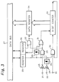
- Fig. 3 is a block diagram of a pulse period measuring circuit to which a method for automatically discriminating scanning modes according to the invention is applied.
- the pulse period measuring circuit is coupled to a controller via a data bus such that the mode of driving a tape is changed by the controller.
- a mask signal and a horizontal synchronizing signal are input through a terminal 21 and a terminal 22, respectively.
- the mask signal is used to stop measurement of a period in the absence of a reproduced signal from the reproducing head in order to prevent distortion in measurement of the periods due to a noise caused by reproduction in a wrong scanning mode. That is, for preventing an erroneous operation caused by a noise, a horizontal synchronizing signal input from the terminal 22 is masked when no reproduced signal is supplied from the reproducing head.
- the respective signals from the terminals 21 and 22 are waveform-shaped in waveform shaping circuits 23 and 24.
- the waveform shaping circuit 23 outputs an inverted signal to a first input terminal of an AND circuit 25.
- the waveform shaping circuit 24 outputs a signal such that a rising detecting circuit 26 detects the rising edge of the signal.
- the rising detecting circuit 26 gives its output signal to a second input terminal of the AND circuit 25.
- An 8-bit counter start flag which is input from the controller (not shown) through the data bus 27, is supplied to a register 28.
- the 8-bit counter start flag is one for starting measurement of periods and for behaving as an interface with software.
- An output signal from the register 28 is applied to a rising detecting circuit 29, a third input terminal of the AND circuit 25 and a first input terminal of an AND circuit 30.
- a signal detected by the rising detecting circuit 29 is supplied to a first input terminal of an OR circuit 31.
- An output signal from the AND circuit 25 is supplied to a second input terminal of the OR circuit 31 and to a first input terminal of an AND circuit 32.
- An output signal from the OR circuit 31 is supplied to an 8-bit counter 33 as a clear signal.
- An output signal from the AND circuit 30 is supplied to the 8-bit counter 33.
- the 8-bit counter 33 counts the period measuring clock signals, and stops the counting when reaching the maximum value.
- the 8-bit counter 33 is cleared.
- the value of the 8-bit counter 33 is taken in a data register 34 in eight bits, and it is supplied to a third input terminal of the AND circuit in the negative logic.
- the value stored in the data register 34 indicates the period of the reproduced horizontal synchronizing signal.
- a data register validity flag which is input from the controller through the data bus 27 and indicating that an effective data is stored in the data register, is stored in a register 36 and then supplied to a second terminal of the AND gate 32 in the negative logic.
- the AND circuit 32 supplies a latch output signal to a data register 34 and to a register 36.
- an output signal from the data register 34 is supplied to the controller through the data bus 27.
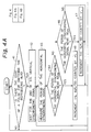
- Figs. 4A and 4B is a flow chart showing an algorithm for automatically discriminating scanning modes, using the pulse period measuring circuit explained above.
- the edge of a pulse for switching the reproducing head is detected in step 41, and the end of the vertical synchronizing signal is waited for in step 42.
- measurement of the period of the horizontal synchronizing signal is started (step 43). Measurement of the period of the horizontal synchronizing signal is conducted only for effective reproduced signals due to the behavior of the mask signal.
- step 44 it is judged whether or not the period of the horizontal synchronizing signal is near 53 ⁇ s (reference value).
- This reference value is a horizontal synchronizing period when signals recorded on a tape in the mode of 625 lines 50Hz have been reproduced in the mode of 525 lines and 60Hz. If the period of the horizontal synchronizing signal is near 53 ⁇ s, then it is possible that the servo operating mode is inconsistent with the scanning mode for signals on the tape, and the counter indicating the inconsistency is incremented by one (step 45). In step 44, if the period of the horizontal synchronizing signal is not near 53 ⁇ s, the process goes to the step 46.
- step 46 it is judged whether or not the period of the horizontal synchronizing signal is near 76 ⁇ s. If it is near 76 ⁇ s, it is possible that the servo operating mode is inconsistent with the scanning mode on the tape, and the counter indicating the inconsistency is incremented by one (step 47). In the measurements in steps 44 and 46, comparison with the reference values is done with a certain margin, considering some error may occur in measurement.
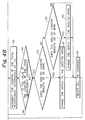
- step 48 the counter indicating the total occurrences of measurements is incremented by one.
- step 49 it is judged whether or not the value of the counter indicating the total occurrences of measurements has reached 100. If it is below 100, the process is returned to step 43. If the total occurrences of measurements has reached 100, the process goes ahead to step 50.
- step 50 it is judged whether or not the value of the counter for the mode of 625 lines and 50Hz is 25 or more. If it is 25 or more, it is regarded that the servo operation mode is certainly inconsistent with the scanning mode of the signal recorded on the tape, and the servo operation is changed to the mode of 625 lines and 50Hz corresponding to the scanning mode of the signal recorded on the tape.
- step 50 if the value of the counter for the mode of 625 lines and 50Hz is less than 25, the process goes to step 52.
- step 52 it is judged whether or not the value of the counter for the mode of 525 lines and 60Hz is 25 or more. If it is 25 or more, it is regarded that the servo operation mode is certainly inconsistent with the scanning mode of the signal recorded on the tape, and the servo operation is changed to the mode of 525 lines and 60Hz consistent with the scanning mode of the signal recorded on the tape (step 53).
- step 53 After the steps 51, 52 (in case of the value for the mode of 525 lines and 60Hz being less than 25) and 53, the process goes to step 54.
- step 54 all the counters are reset for availability to the next measurement.
- VTRs coping with a plurality of TV signal modes and suitable for employing the present invention use highly functional microcomputers for their control such that their servo control itself is realized by software.
- the invention can be realized by incorporating some of servo functions in a servo control circuit and by incorporating the others of the servo functions in software.
- the method described above for automatically discriminating scanning modes uses, for the discrimination, horizontal synchronizing signals amounting to several hundreds in a single picture plane, it ensures highly accurate discrimination and enables realization of units or apparatuses requiring no manipulation by users. Additionally, the method well matches with systems using a servo control circuit and can be brought in practice at a low cost. The method further enables realization of units or apparatuses taking only a short time for discrimination and excellent in manipulation.
Landscapes
- Engineering & Computer Science (AREA)
- Multimedia (AREA)
- Signal Processing (AREA)
- Television Signal Processing For Recording (AREA)
- Adjustment Of The Magnetic Head Position Track Following On Tapes (AREA)
Abstract
Description
- This invention relates to automatic discrimination of one scanning mode from another by which video signals were recorded on a recording medium, such as a tape, with a video recorder/reproducer, such as a video tape recorder.
- As well known, some modes of scanning video signals are being employed worldwide. Apart from the scanning modes, there are also some modes for modulating luminance signals and color-difference signals. To meet the situations, some video tape recorders (hereinafter called VTRs) or other video signal recorders/reproducers are designed to cope with some different broadcasting modes.
- In order to reproduce video signals recorded in different areas using different broadcasting modes, such a video signal recorder/reproducer includes a plurality of signal processing circuits in accordance with respective recording formats such that one of the circuits is selectively activated to reproduce a particular signal in accordance with the format used in recording the particular signal. Typically, users can select one of the signal processing circuits by manipulation of a changeover switch. Differences in scanning mode are greatly related to track patterns on recording media, and inconsistency in scanning mode makes it impossible to even obtain reproduced signals from a recording medium. Discrimination of scanning modes is therefore considered difficult.
- In this respect, a method for automatically discriminating scanning modes has been put in practical use. The method discriminates scanning modes by counting the number of horizontal synchronizing signals contained in a field.
- The method may enable discrimination of scanning modes with a sufficient preciseness during a normal reproducing operation. However, during a reproducing operation at a different speed, such as "cue" or "review", noise bars appear on the screen and disturb precise discrimination. If an error occurs in discrimination, a large noise enters in the reproduced signal. That is, this method is weak at noises, and it is liable to cause errors in determination.
- The present invention is concerned with automatically discriminating scanning modes with better precision.
- The invention lies in a method for automatically discriminating scanning modes, which includes a first scanning mode with a first horizontal scanning frequency, a second scanning mode with a second horizontal scanning frequency, and a period measuring portion for measuring the period of horizontal synchronizing signals contained in recorded signals, the period measuring portion being provided with a range for discriminating the period of horizontal synchronizing signals such that when the period of horizontal synchronizing signals in said recorded signals reproduced in one of said scanning modes is outside said range for discriminating the period, said recorded signals are reproduced in the other of said scanning modes.
- When the reproduction is not done properly, periods of horizontal synchronizing signals of the two scanning modes become largely distant. These largely distant periods of horizontal synchronizing signals are compared with two reference signals in a comparing portion, and a switching signal is sent to a servo control circuit.
- A specific embodiment of the present invention will now be described by way of example with reference to the accompanying drawings, in which:
- Fig. 1 is a diagram showing a principle of a video tape recorder to which the present invention is applied;
- Fig. 2 is a diagram indicating periods of horizontal synchronizing signals supplied to a comparing portion;
- Fig. 3 is a block diagram of a pulse period measuring circuit to which a method for automatically discriminating scanning modes according to the invention is applied; and
- Figs. 4A and 4B are flow charts indicating an algorithm for automatically discriminating scanning modes by using the pulse period measuring circuit.
- Fig. 1 is a block diagram of the VTR, which shows a principle of the method for automatically discriminating scanning methods according to the invention. For simplicity, here is taken a case where two scanning modes, namely, the NTSC mode (525 lines (number of scanning lines) and 60Hz (horizontal scanning period)) and the PAL mode (625 lines and 50Hz), are to be discriminated.
- In Fig. 1, a
rotating drum 1 is provided with a recording head and a reproducing head (neither shown), and is wound with amagnetic tape 2 on which video signals have been recorded. The rotatingdrum 1 is rotated by adrum motor 3. Themagnetic tape 2 is fed out by acapstan motor 4. Signals reproduced by the reproducing head are supplied to a video demodulatingcircuit 5, and are demodulated through predetermined processing. At the same time, horizontal synchronizing signals of the recorded signals are also demodulated. The horizontal synchronizing signals output from the video demodulatingcircuit 5 are supplied to aperiod measuring portion 6. - The
period measuring portion 6 measures the period of the horizontal synchronizing signals supplied. If the video signals reproduced by the reproducing head are of the mode of 525 lines and 60Hz, then the period of the horizontal synchronizing signals is about 63.5µs. If they are of the mode of 626 lines and 50Hz, the period is about 64µs. Theperiod measuring portion 6 gives its output signal to a comparing portion 7 includingcomparators 7a and 7b. The comparator 7a is supplied with a first reference signal from aterminal 8, and thecomparator 7b with a second reference signal from aterminal 9. The comparing portion 7 compares the period of horizontal synchronizing signals measured by theperiod measuring portion 6 with the predetermined reference signals, and generates and supplies a switching signal to aservo control circuit 10 referred to later. Outputs from thecomparators 7a and 7b are supplied to theservo control circuit 10. In response to the switching signal received, theservo control circuit 10 supplies a control signal to thedrum motor 3 and to thecapstan motor 4. - Fig. 2 shows how to discriminate periods of horizontal synchronizing signals in reproduced signals measured by the
period measuring portion 6, taking periods of horizontal synchronizing signals along the abscissa. In Fig. 2, when reproduction of signals is being carried out properly (when a signal with the mode of 525 lines and 60Hz is being reproduced in the mode of 525 lines and 60 Hz or when a signal with the mode of 625 lines and 50 Hz is being reproduced in the mode of 625 lines and 50 Hz), periods of the respective horizontal synchronizing signals are close to each other as shown at lla (horizontal synchronizing signals in the mode of 525 lines and 60Hz) and 11b (horizontal synchronizing signals in the mode of 625 lines and 50Hz). - On the other hand, when reproduction of signals is being carried out erroneously (when a signal recorded in the mode of 525 lines and 60Hz is being reproduced in the mode of 625 lines and 50Hz or when signals with the mode of 625 lines and 50Hz are being reproduced in the mode of 525 lines and 60 Hz), periods of the respective horizontal synchronizing signals are far apart as shown at 12a (horizontal synchronizing signals recorded in the mode of 525 lines and 60Hz but reproduced in the mode of 625 lines and 60Hz) and 12b (horizontal synchronizing signal recorded in the mode of 525 lines and 60Hz but reproduced in the mode of 625 lines and 50 Hz) for the reasons shown below. That is, the rotating head for reproducing signals recorded on a tape rotates at the speed of rotation synchronizing with a vertical scanning frequency, and these two scanning modes have a relatively large difference in vertical scanning frequency as large as 59.96:50. Therefore, if reproduction is done in a wrong scanning mode, periods of horizontal synchronizing signals of the reproduced signals obtained from the rotating head are detected as having a large difference as large as about 20% although the periods of their normal horizontal synchronizing signals are substantially the same, because the speed of the reproducing head relative to the tape varies. That is, the large separation of 12a and 12b is caused by the speed of the reproducing head relative to a magnetic tape used as a recording medium being substantially proportional to the period of the vertical synchronizing signal. A
range 13a defined about 12a is the range for thecomparator 7b to determine coincidence of a measured period therewith, and arange 13b defined about 12b is the range for the comparator 7a to determine coincidence of a measured period therewith. - The comparing portion 7 compares the largely distant periods shown at 12a and 12b of the horizontal synchronizing signals with two reference signals, and if necessary, supplies a switching signal to the
servo control circuit 10. For example, in case of Fig. 2, if the measured period of the horizontal synchronizing signals is near the first reference signal supplied through theterminal 8, it is determined that a video signal recorded in the mode of 525 lines and 60Hz is erroneously being reproduced in the mode of 625 lines and 50 Hz by theservo control circuit 10, and the comparing portion 7 supplies theservo control circuit 10 with a switching signal to make it execute a servo operation in the mode of 525 lines and 60Hz corresponding to the scanning mode for signals on the tape. If the reproduction proceeds in an erroneous scanning mode, the reproducing head moves across recording tracks on the tape and causes reproduced signals to be cut into pieces by a noise. Nevertheless, even with such intermittent reproduced signals, because the period of horizontal synchronizing signals is as short as 100µs, it is sufficiently possible to measure the period of its horizontal synchronizing signals, and a high speed discrimination is possible. In response to the switching signal, theservo control circuit 10 outputs a control signal for the mode of 525 lines and 60Hz to thedrum 3 and to thecapstan 4. - On the other hand, if the measured period of the horizontal synchronizing signals is near the second reference signal supplied through the
terminal 9, then it is determined that a video signal recorded in the mode of 625 lines and 50Hz is erroneously being reproduced in the mode of 525 lines and 60Hz by theservo control circuit 10, and the comparing portion 7 supplies theservo control circuit 10 with a switching signal to make it execute a servo operation in the mode of 625 lines and 50 Hz corresponding to the scanning mode for signals on the tape. In response to the switching signal, theservo control circuit 10 outputs a control signal for the mode of 625 lines and 50Hz to thedrum 3 and to thecapstan 4. - Although an operation has been explained above with regards a case for discriminating two scanning modes for simplicity, discrimination of three or more scanning modes can readily be realized on the basis of the same concept.
- Fig. 3 is a block diagram of a pulse period measuring circuit to which a method for automatically discriminating scanning modes according to the invention is applied. The pulse period measuring circuit is coupled to a controller via a data bus such that the mode of driving a tape is changed by the controller.
- In Fig. 3, a mask signal and a horizontal synchronizing signal are input through a terminal 21 and a terminal 22, respectively. The mask signal is used to stop measurement of a period in the absence of a reproduced signal from the reproducing head in order to prevent distortion in measurement of the periods due to a noise caused by reproduction in a wrong scanning mode. That is, for preventing an erroneous operation caused by a noise, a horizontal synchronizing signal input from the terminal 22 is masked when no reproduced signal is supplied from the reproducing head. The respective signals from the terminals 21 and 22 are waveform-shaped in
waveform shaping circuits 23 and 24. The waveform shaping circuit 23 outputs an inverted signal to a first input terminal of anAND circuit 25. Thewaveform shaping circuit 24 outputs a signal such that a rising detectingcircuit 26 detects the rising edge of the signal. The risingdetecting circuit 26 gives its output signal to a second input terminal of theAND circuit 25. - An 8-bit counter start flag, which is input from the controller (not shown) through the
data bus 27, is supplied to aregister 28. The 8-bit counter start flag is one for starting measurement of periods and for behaving as an interface with software. An output signal from theregister 28 is applied to a rising detectingcircuit 29, a third input terminal of the ANDcircuit 25 and a first input terminal of an ANDcircuit 30. A signal detected by the rising detectingcircuit 29 is supplied to a first input terminal of anOR circuit 31. An output signal from the ANDcircuit 25 is supplied to a second input terminal of theOR circuit 31 and to a first input terminal of an ANDcircuit 32. An output signal from theOR circuit 31 is supplied to an 8-bit counter 33 as a clear signal. - A clock signal for measurement of periods of horizontal synchronizing signals ia supplied to a second input terminal of the AND
circuit 30 through a terminal 35. An output signal from the ANDcircuit 30 is supplied to the 8-bit counter 33. The 8-bit counter 33 counts the period measuring clock signals, and stops the counting when reaching the maximum value. When a horizontal synchronizing signal is input, the 8-bit counter 33 is cleared. The value of the 8-bit counter 33 is taken in adata register 34 in eight bits, and it is supplied to a third input terminal of the AND circuit in the negative logic. The value stored in the data register 34 indicates the period of the reproduced horizontal synchronizing signal. - A data register validity flag, which is input from the controller through the
data bus 27 and indicating that an effective data is stored in the data register, is stored in aregister 36 and then supplied to a second terminal of the ANDgate 32 in the negative logic. On the basis of two signals supplied, the ANDcircuit 32 supplies a latch output signal to adata register 34 and to aregister 36. In response to the latch output, an output signal from the data register 34 is supplied to the controller through thedata bus 27. - Figs. 4A and 4B is a flow chart showing an algorithm for automatically discriminating scanning modes, using the pulse period measuring circuit explained above. In order to start the measurement after a vertical synchronizing signal terminates, the edge of a pulse for switching the reproducing head is detected in
step 41, and the end of the vertical synchronizing signal is waited for instep 42. After the period of the vertical synchronizing signal, measurement of the period of the horizontal synchronizing signal is started (step 43). Measurement of the period of the horizontal synchronizing signal is conducted only for effective reproduced signals due to the behavior of the mask signal. - In
step 44, it is judged whether or not the period of the horizontal synchronizing signal is near 53µs (reference value). This reference value is a horizontal synchronizing period when signals recorded on a tape in the mode of 625 lines 50Hz have been reproduced in the mode of 525 lines and 60Hz. If the period of the horizontal synchronizing signal is near 53µs, then it is possible that the servo operating mode is inconsistent with the scanning mode for signals on the tape, and the counter indicating the inconsistency is incremented by one (step 45). Instep 44, if the period of the horizontal synchronizing signal is not near 53µs, the process goes to thestep 46. - In
step 46, it is judged whether or not the period of the horizontal synchronizing signal is near 76µs. If it is near 76µs, it is possible that the servo operating mode is inconsistent with the scanning mode on the tape, and the counter indicating the inconsistency is incremented by one (step 47). In the measurements insteps - The
steps 45, 46 (when the period of the horizontal synchronizing signal is not near 76µs) and thestep 47 are followed bystep 48. That is, instep 48, the counter indicating the total occurrences of measurements is incremented by one. Instep 49, it is judged whether or not the value of the counter indicating the total occurrences of measurements has reached 100. If it is below 100, the process is returned to step 43. If the total occurrences of measurements has reached 100, the process goes ahead to step 50. - In
step 50, it is judged whether or not the value of the counter for the mode of 625 lines and 50Hz is 25 or more. If it is 25 or more, it is regarded that the servo operation mode is certainly inconsistent with the scanning mode of the signal recorded on the tape, and the servo operation is changed to the mode of 625 lines and 50Hz corresponding to the scanning mode of the signal recorded on the tape. - In
step 50, if the value of the counter for the mode of 625 lines and 50Hz is less than 25, the process goes to step 52. Instep 52, it is judged whether or not the value of the counter for the mode of 525 lines and 60Hz is 25 or more. If it is 25 or more, it is regarded that the servo operation mode is certainly inconsistent with the scanning mode of the signal recorded on the tape, and the servo operation is changed to the mode of 525 lines and 60Hz consistent with the scanning mode of the signal recorded on the tape (step 53). After thesteps 51, 52 (in case of the value for the mode of 525 lines and 60Hz being less than 25) and 53, the process goes to step 54. Instep 54, all the counters are reset for availability to the next measurement. - Many VTRs coping with a plurality of TV signal modes and suitable for employing the present invention use highly functional microcomputers for their control such that their servo control itself is realized by software. In these VTRs equipped with such software servo, the invention can be realized by incorporating some of servo functions in a servo control circuit and by incorporating the others of the servo functions in software.
- Since the method described above for automatically discriminating scanning modes uses, for the discrimination, horizontal synchronizing signals amounting to several hundreds in a single picture plane, it ensures highly accurate discrimination and enables realization of units or apparatuses requiring no manipulation by users. Additionally, the method well matches with systems using a servo control circuit and can be brought in practice at a low cost. The method further enables realization of units or apparatuses taking only a short time for discrimination and excellent in manipulation.
Claims (8)
- A circuit for automatically discriminating scanning modes in a video signal reproducing apparatus, comprising;
a rotating drum for recording video signals on a video tape,
a motor for rotating said rotating drum,
a driving circuit for driving said motor,
a measuring means for measuring a period of horizontal synchronizing signals included in recording signals,
a discriminating circuit for discriminating between a first scanning mode having a first horizontal scanning frequency and a second scanning mode having a second horizontal scanning frequency on the basis of an output result of said measuring means,
a controlling circuit for reproducing said recording signals using one scanning mode, and for reproducing said recording signals using the other scanning mode in the case that said period of said horizontal synchronizing signals is out of a period discrimination range, on the basis of an output signal from said discriminating circuit. - The circuit according to claim 1 wherein the discrimination by said discriminating circuit is done plural, and said recording signals are reproduced by said first scanning mode or said second scanning mode according to a previous result of said discrimination.
- The circuit according to claim 1 or 2 wherein a capstan motor is also provided, and said motor and said capstan motor are driven according to an output result of said discriminating circuit.
- The circuit according to claim 3 wherein said discriminating circuit discriminates a period of one horizontal synchronizing signal and drives said motor and said capstan motor according to a result of the discrimination.
- The circuit according to claim 4 wherein said first horizontal synchronizing signal and said second horizontal synchronizing signal are about 63.5µs and 64µs respectively.
- The circuit according to claim 3 wherein said discriminating circuit discriminates a period of one vertical synchronizing signal, and drives said motor and said capstan motor on the basis of a result of the discrimination.
- The circuit according to claim 6 wherein a first vertical scanning frequency and a second vertical scanning frequency is about 60Hz and 50Hz respectively.
- A video signal reproducing apparatus having a circuit as claimed in any preceding claim.
Applications Claiming Priority (3)
| Application Number | Priority Date | Filing Date | Title |
|---|---|---|---|
| JP24635393 | 1993-09-07 | ||
| JP246353/93 | 1993-09-07 | ||
| JP5246353A JPH0779450A (en) | 1993-09-07 | 1993-09-07 | Scanning system automatic discrimination method |
Publications (2)
| Publication Number | Publication Date |
|---|---|
| EP0647939A1 true EP0647939A1 (en) | 1995-04-12 |
| EP0647939B1 EP0647939B1 (en) | 2000-04-05 |
Family
ID=17147300
Family Applications (1)
| Application Number | Title | Priority Date | Filing Date |
|---|---|---|---|
| EP94306549A Expired - Lifetime EP0647939B1 (en) | 1993-09-07 | 1994-09-06 | Automatic discrimination of scanning modes by which video signals were recorded |
Country Status (5)
| Country | Link |
|---|---|
| EP (1) | EP0647939B1 (en) |
| JP (1) | JPH0779450A (en) |
| KR (1) | KR100307109B1 (en) |
| CN (1) | CN1064475C (en) |
| AT (1) | ATE191580T1 (en) |
Citations (9)
| Publication number | Priority date | Publication date | Assignee | Title |
|---|---|---|---|---|
| JPS5643891A (en) * | 1979-09-17 | 1981-04-22 | Sony Corp | Video signal reproducing device |
| JPS5711586A (en) * | 1980-06-25 | 1982-01-21 | Toshiba Corp | Automatic switching circuit for magnetic reproducing device |
| JPS5711590A (en) * | 1980-06-25 | 1982-01-21 | Toshiba Corp | Magnetic reproducing device |
| US4346397A (en) * | 1978-01-23 | 1982-08-24 | Victor Company Of Japan, Ltd. | Apparatus for reproducing a video signal of one system with conversion to a video signal of another system |
| GB2114849A (en) * | 1982-02-13 | 1983-08-24 | Mitsubishi Electric Corp | Video reproducing apparatus |
| JPS6035888A (en) * | 1984-06-13 | 1985-02-23 | Matsushita Electric Ind Co Ltd | Rotary head type magnetic picture recording and reproducing device |
| JPS6239995A (en) * | 1985-08-16 | 1987-02-20 | Fujitsu Ltd | Television signal processor |
| EP0228240A1 (en) * | 1985-12-18 | 1987-07-08 | Matsushita Electric Industrial Co., Ltd. | Magnetic tape recording/reproducing apparatus |
| JPH02285780A (en) * | 1989-04-26 | 1990-11-26 | Sony Corp | Discrimination circuit |
-
1993
- 1993-09-07 JP JP5246353A patent/JPH0779450A/en active Pending
-
1994
- 1994-09-06 KR KR1019940022318A patent/KR100307109B1/en not_active IP Right Cessation
- 1994-09-06 EP EP94306549A patent/EP0647939B1/en not_active Expired - Lifetime
- 1994-09-06 AT AT94306549T patent/ATE191580T1/en not_active IP Right Cessation
- 1994-09-07 CN CN94113705A patent/CN1064475C/en not_active Expired - Fee Related
Patent Citations (9)
| Publication number | Priority date | Publication date | Assignee | Title |
|---|---|---|---|---|
| US4346397A (en) * | 1978-01-23 | 1982-08-24 | Victor Company Of Japan, Ltd. | Apparatus for reproducing a video signal of one system with conversion to a video signal of another system |
| JPS5643891A (en) * | 1979-09-17 | 1981-04-22 | Sony Corp | Video signal reproducing device |
| JPS5711586A (en) * | 1980-06-25 | 1982-01-21 | Toshiba Corp | Automatic switching circuit for magnetic reproducing device |
| JPS5711590A (en) * | 1980-06-25 | 1982-01-21 | Toshiba Corp | Magnetic reproducing device |
| GB2114849A (en) * | 1982-02-13 | 1983-08-24 | Mitsubishi Electric Corp | Video reproducing apparatus |
| JPS6035888A (en) * | 1984-06-13 | 1985-02-23 | Matsushita Electric Ind Co Ltd | Rotary head type magnetic picture recording and reproducing device |
| JPS6239995A (en) * | 1985-08-16 | 1987-02-20 | Fujitsu Ltd | Television signal processor |
| EP0228240A1 (en) * | 1985-12-18 | 1987-07-08 | Matsushita Electric Industrial Co., Ltd. | Magnetic tape recording/reproducing apparatus |
| JPH02285780A (en) * | 1989-04-26 | 1990-11-26 | Sony Corp | Discrimination circuit |
Non-Patent Citations (5)
| Title |
|---|
| PATENT ABSTRACTS OF JAPAN vol. 11, no. 220 (E - 524) 16 July 1987 (1987-07-16) * |
| PATENT ABSTRACTS OF JAPAN vol. 15, no. 58 (E - 1032) 12 February 1991 (1991-02-12) * |
| PATENT ABSTRACTS OF JAPAN vol. 5, no. 99 (E - 063) 26 June 1981 (1981-06-26) * |
| PATENT ABSTRACTS OF JAPAN vol. 6, no. 72 (E - 105) 7 May 1982 (1982-05-07) * |
| PATENT ABSTRACTS OF JAPAN vol. 9, no. 159 (E - 326) 4 July 1985 (1985-07-04) * |
Also Published As
| Publication number | Publication date |
|---|---|
| CN1111796A (en) | 1995-11-15 |
| EP0647939B1 (en) | 2000-04-05 |
| KR950009601A (en) | 1995-04-24 |
| CN1064475C (en) | 2001-04-11 |
| KR100307109B1 (en) | 2001-12-15 |
| JPH0779450A (en) | 1995-03-20 |
| ATE191580T1 (en) | 2000-04-15 |
Similar Documents
| Publication | Publication Date | Title |
|---|---|---|
| US5046167A (en) | Video tape recorder with a video printing controller | |
| EP0647939B1 (en) | Automatic discrimination of scanning modes by which video signals were recorded | |
| US4349832A (en) | Digital data rate corrector and time base corrector | |
| CA1279927C (en) | Information recording and reproducing apparatus | |
| US4914528A (en) | Detection of a synchronizing signal in a magnetic recording/reproducing apparatus | |
| US5694263A (en) | VCR head cleaning system that automatically detects head clogging upon playback | |
| KR100197592B1 (en) | Discriminating method for broadcasting system in a vcr | |
| JP2714162B2 (en) | Servo error detector for data recording / reproducing device | |
| JPH0463454B2 (en) | ||
| US6272280B1 (en) | Apparatus for reproducing image data from a tape-shaped recording medium | |
| JPH09251677A (en) | Reproducing device and mode discriminating method | |
| JP2534900B2 (en) | Device for discriminating the recording system of FM-modulated video signal | |
| JP2678309B2 (en) | Head discriminating signal format discriminating device at the time of recording / reproducing in a magnetic recording / reproducing device | |
| JPH04326268A (en) | Magnetic recording and reproducing device | |
| JP3216368B2 (en) | Magnetic recording / reproducing device | |
| KR0170257B1 (en) | Circuit and method for discriminating disc according to broadcast type | |
| JP2803450B2 (en) | Identification signal detection device | |
| JP2678307B2 (en) | Tracking detection device in magnetic recording / reproducing device | |
| KR0176453B1 (en) | Recording and reproducing apparatus | |
| KR940008802B1 (en) | Automatic reading method | |
| JPH0646481B2 (en) | Rotating head type digital signal recording / reproducing device | |
| JPH0463453B2 (en) | ||
| JPS6115637B2 (en) | ||
| JPH02123548A (en) | Tracking method for magnetic reproducing device | |
| JPH04114343A (en) | Magnetic tape reproducing device |
Legal Events
| Date | Code | Title | Description |
|---|---|---|---|
| PUAI | Public reference made under article 153(3) epc to a published international application that has entered the european phase |
Free format text: ORIGINAL CODE: 0009012 |
|
| AK | Designated contracting states |
Kind code of ref document: A1 Designated state(s): AT CH FR GB LI |
|
| 17P | Request for examination filed |
Effective date: 19950830 |
|
| 17Q | First examination report despatched |
Effective date: 19980605 |
|
| GRAG | Despatch of communication of intention to grant |
Free format text: ORIGINAL CODE: EPIDOS AGRA |
|
| GRAG | Despatch of communication of intention to grant |
Free format text: ORIGINAL CODE: EPIDOS AGRA |
|
| GRAH | Despatch of communication of intention to grant a patent |
Free format text: ORIGINAL CODE: EPIDOS IGRA |
|
| GRAH | Despatch of communication of intention to grant a patent |
Free format text: ORIGINAL CODE: EPIDOS IGRA |
|
| GRAA | (expected) grant |
Free format text: ORIGINAL CODE: 0009210 |
|
| AK | Designated contracting states |
Kind code of ref document: B1 Designated state(s): AT CH FR GB LI |
|
| REF | Corresponds to: |
Ref document number: 191580 Country of ref document: AT Date of ref document: 20000415 Kind code of ref document: T |
|
| REG | Reference to a national code |
Ref country code: CH Ref legal event code: NV Representative=s name: ISLER & PEDRAZZINI AG Ref country code: CH Ref legal event code: EP |
|
| ET | Fr: translation filed | ||
| PLBE | No opposition filed within time limit |
Free format text: ORIGINAL CODE: 0009261 |
|
| STAA | Information on the status of an ep patent application or granted ep patent |
Free format text: STATUS: NO OPPOSITION FILED WITHIN TIME LIMIT |
|
| 26N | No opposition filed | ||
| REG | Reference to a national code |
Ref country code: GB Ref legal event code: IF02 |
|
| REG | Reference to a national code |
Ref country code: CH Ref legal event code: PCAR Free format text: ISLER & PEDRAZZINI AG;POSTFACH 1772;8027 ZUERICH (CH) |
|
| PGFP | Annual fee paid to national office [announced via postgrant information from national office to epo] |
Ref country code: FR Payment date: 20080915 Year of fee payment: 15 Ref country code: AT Payment date: 20080912 Year of fee payment: 15 |
|
| PGFP | Annual fee paid to national office [announced via postgrant information from national office to epo] |
Ref country code: GB Payment date: 20080910 Year of fee payment: 15 |
|
| PGFP | Annual fee paid to national office [announced via postgrant information from national office to epo] |
Ref country code: CH Payment date: 20081002 Year of fee payment: 15 |
|
| REG | Reference to a national code |
Ref country code: CH Ref legal event code: PL |
|
| GBPC | Gb: european patent ceased through non-payment of renewal fee |
Effective date: 20090906 |
|
| REG | Reference to a national code |
Ref country code: FR Ref legal event code: ST Effective date: 20100531 |
|
| PG25 | Lapsed in a contracting state [announced via postgrant information from national office to epo] |
Ref country code: AT Free format text: LAPSE BECAUSE OF NON-PAYMENT OF DUE FEES Effective date: 20090906 |
|
| PG25 | Lapsed in a contracting state [announced via postgrant information from national office to epo] |
Ref country code: FR Free format text: LAPSE BECAUSE OF NON-PAYMENT OF DUE FEES Effective date: 20090930 |
|
| PG25 | Lapsed in a contracting state [announced via postgrant information from national office to epo] |
Ref country code: LI Free format text: LAPSE BECAUSE OF NON-PAYMENT OF DUE FEES Effective date: 20090930 Ref country code: CH Free format text: LAPSE BECAUSE OF NON-PAYMENT OF DUE FEES Effective date: 20090930 |
|
| PG25 | Lapsed in a contracting state [announced via postgrant information from national office to epo] |
Ref country code: GB Free format text: LAPSE BECAUSE OF NON-PAYMENT OF DUE FEES Effective date: 20090906 |