EP0647833A1 - Impedance detector, in particular for radiosonde operation, as well as a process for the manufacture of a detector - Google Patents
Impedance detector, in particular for radiosonde operation, as well as a process for the manufacture of a detector Download PDFInfo
- Publication number
- EP0647833A1 EP0647833A1 EP94850150A EP94850150A EP0647833A1 EP 0647833 A1 EP0647833 A1 EP 0647833A1 EP 94850150 A EP94850150 A EP 94850150A EP 94850150 A EP94850150 A EP 94850150A EP 0647833 A1 EP0647833 A1 EP 0647833A1
- Authority
- EP
- European Patent Office
- Prior art keywords
- detector
- filament
- core filament
- electrodes
- core
- Prior art date
- Legal status (The legal status is an assumption and is not a legal conclusion. Google has not performed a legal analysis and makes no representation as to the accuracy of the status listed.)
- Granted
Links
- 238000000034 method Methods 0.000 title claims abstract description 35
- 230000008569 process Effects 0.000 title claims abstract description 31
- 238000004519 manufacturing process Methods 0.000 title claims abstract description 22
- 239000011810 insulating material Substances 0.000 claims abstract description 15
- 239000000758 substrate Substances 0.000 claims abstract description 12
- 230000015572 biosynthetic process Effects 0.000 claims abstract description 4
- 238000005259 measurement Methods 0.000 claims description 29
- 239000011521 glass Substances 0.000 claims description 22
- 238000010438 heat treatment Methods 0.000 claims description 18
- 239000011248 coating agent Substances 0.000 claims description 10
- 238000000576 coating method Methods 0.000 claims description 10
- XLYOFNOQVPJJNP-UHFFFAOYSA-N water Substances O XLYOFNOQVPJJNP-UHFFFAOYSA-N 0.000 claims description 7
- 239000000463 material Substances 0.000 claims description 6
- 239000000853 adhesive Substances 0.000 claims description 4
- 230000001070 adhesive effect Effects 0.000 claims description 4
- 239000003990 capacitor Substances 0.000 claims description 4
- 238000005530 etching Methods 0.000 claims description 4
- 239000000919 ceramic Substances 0.000 claims description 3
- 230000001419 dependent effect Effects 0.000 claims description 2
- 238000001035 drying Methods 0.000 claims description 2
- 238000005485 electric heating Methods 0.000 claims 1
- 238000004804 winding Methods 0.000 claims 1
- 238000010276 construction Methods 0.000 description 22
- 229920006254 polymer film Polymers 0.000 description 16
- 229910052751 metal Inorganic materials 0.000 description 6
- 239000002184 metal Substances 0.000 description 6
- 238000001704 evaporation Methods 0.000 description 5
- 239000011152 fibreglass Substances 0.000 description 5
- 229920000642 polymer Polymers 0.000 description 5
- 239000004593 Epoxy Substances 0.000 description 4
- 238000009529 body temperature measurement Methods 0.000 description 4
- 230000008020 evaporation Effects 0.000 description 4
- BASFCYQUMIYNBI-UHFFFAOYSA-N platinum Chemical compound [Pt] BASFCYQUMIYNBI-UHFFFAOYSA-N 0.000 description 4
- 230000008901 benefit Effects 0.000 description 3
- 238000011161 development Methods 0.000 description 3
- 230000000694 effects Effects 0.000 description 3
- 239000000835 fiber Substances 0.000 description 3
- 238000001465 metallisation Methods 0.000 description 3
- 238000005520 cutting process Methods 0.000 description 2
- 238000010586 diagram Methods 0.000 description 2
- 230000002349 favourable effect Effects 0.000 description 2
- 230000008014 freezing Effects 0.000 description 2
- 238000007710 freezing Methods 0.000 description 2
- 239000012774 insulation material Substances 0.000 description 2
- 230000005855 radiation Effects 0.000 description 2
- 239000000126 substance Substances 0.000 description 2
- 238000012546 transfer Methods 0.000 description 2
- 238000007738 vacuum evaporation Methods 0.000 description 2
- 206010060904 Freezing phenomenon Diseases 0.000 description 1
- 239000011149 active material Substances 0.000 description 1
- 230000008859 change Effects 0.000 description 1
- 238000012937 correction Methods 0.000 description 1
- 125000004122 cyclic group Chemical group 0.000 description 1
- 238000000151 deposition Methods 0.000 description 1
- 230000008030 elimination Effects 0.000 description 1
- 238000003379 elimination reaction Methods 0.000 description 1
- 238000005516 engineering process Methods 0.000 description 1
- 125000003700 epoxy group Chemical group 0.000 description 1
- 230000002452 interceptive effect Effects 0.000 description 1
- 239000007788 liquid Substances 0.000 description 1
- 238000002844 melting Methods 0.000 description 1
- 238000001883 metal evaporation Methods 0.000 description 1
- 239000006060 molten glass Substances 0.000 description 1
- 238000012544 monitoring process Methods 0.000 description 1
- 230000003287 optical effect Effects 0.000 description 1
- 239000004033 plastic Substances 0.000 description 1
- 229920006255 plastic film Polymers 0.000 description 1
- 239000002985 plastic film Substances 0.000 description 1
- 229910052697 platinum Inorganic materials 0.000 description 1
- 229920000647 polyepoxide Polymers 0.000 description 1
- 238000004381 surface treatment Methods 0.000 description 1
- 238000011282 treatment Methods 0.000 description 1
- 238000009736 wetting Methods 0.000 description 1
Images


Classifications
-
- G—PHYSICS
- G01—MEASURING; TESTING
- G01N—INVESTIGATING OR ANALYSING MATERIALS BY DETERMINING THEIR CHEMICAL OR PHYSICAL PROPERTIES
- G01N27/00—Investigating or analysing materials by the use of electric, electrochemical, or magnetic means
- G01N27/02—Investigating or analysing materials by the use of electric, electrochemical, or magnetic means by investigating impedance
- G01N27/22—Investigating or analysing materials by the use of electric, electrochemical, or magnetic means by investigating impedance by investigating capacitance
- G01N27/223—Investigating or analysing materials by the use of electric, electrochemical, or magnetic means by investigating impedance by investigating capacitance for determining moisture content, e.g. humidity
- G01N27/225—Investigating or analysing materials by the use of electric, electrochemical, or magnetic means by investigating impedance by investigating capacitance for determining moisture content, e.g. humidity by using hygroscopic materials
-
- G—PHYSICS
- G01—MEASURING; TESTING
- G01D—MEASURING NOT SPECIALLY ADAPTED FOR A SPECIFIC VARIABLE; ARRANGEMENTS FOR MEASURING TWO OR MORE VARIABLES NOT COVERED IN A SINGLE OTHER SUBCLASS; TARIFF METERING APPARATUS; MEASURING OR TESTING NOT OTHERWISE PROVIDED FOR
- G01D5/00—Mechanical means for transferring the output of a sensing member; Means for converting the output of a sensing member to another variable where the form or nature of the sensing member does not constrain the means for converting; Transducers not specially adapted for a specific variable
- G01D5/12—Mechanical means for transferring the output of a sensing member; Means for converting the output of a sensing member to another variable where the form or nature of the sensing member does not constrain the means for converting; Transducers not specially adapted for a specific variable using electric or magnetic means
- G01D5/14—Mechanical means for transferring the output of a sensing member; Means for converting the output of a sensing member to another variable where the form or nature of the sensing member does not constrain the means for converting; Transducers not specially adapted for a specific variable using electric or magnetic means influencing the magnitude of a current or voltage
- G01D5/24—Mechanical means for transferring the output of a sensing member; Means for converting the output of a sensing member to another variable where the form or nature of the sensing member does not constrain the means for converting; Transducers not specially adapted for a specific variable using electric or magnetic means influencing the magnitude of a current or voltage by varying capacitance
- G01D5/2405—Mechanical means for transferring the output of a sensing member; Means for converting the output of a sensing member to another variable where the form or nature of the sensing member does not constrain the means for converting; Transducers not specially adapted for a specific variable using electric or magnetic means influencing the magnitude of a current or voltage by varying capacitance by varying dielectric
-
- G—PHYSICS
- G01—MEASURING; TESTING
- G01K—MEASURING TEMPERATURE; MEASURING QUANTITY OF HEAT; THERMALLY-SENSITIVE ELEMENTS NOT OTHERWISE PROVIDED FOR
- G01K7/00—Measuring temperature based on the use of electric or magnetic elements directly sensitive to heat ; Power supply therefor, e.g. using thermoelectric elements
- G01K7/34—Measuring temperature based on the use of electric or magnetic elements directly sensitive to heat ; Power supply therefor, e.g. using thermoelectric elements using capacitative elements
- G01K7/343—Measuring temperature based on the use of electric or magnetic elements directly sensitive to heat ; Power supply therefor, e.g. using thermoelectric elements using capacitative elements the dielectric constant of which is temperature dependant
-
- H—ELECTRICITY
- H01—ELECTRIC ELEMENTS
- H01G—CAPACITORS; CAPACITORS, RECTIFIERS, DETECTORS, SWITCHING DEVICES, LIGHT-SENSITIVE OR TEMPERATURE-SENSITIVE DEVICES OF THE ELECTROLYTIC TYPE
- H01G13/00—Apparatus specially adapted for manufacturing capacitors; Processes specially adapted for manufacturing capacitors not provided for in groups H01G4/00 - H01G11/00
-
- Y—GENERAL TAGGING OF NEW TECHNOLOGICAL DEVELOPMENTS; GENERAL TAGGING OF CROSS-SECTIONAL TECHNOLOGIES SPANNING OVER SEVERAL SECTIONS OF THE IPC; TECHNICAL SUBJECTS COVERED BY FORMER USPC CROSS-REFERENCE ART COLLECTIONS [XRACs] AND DIGESTS
- Y10—TECHNICAL SUBJECTS COVERED BY FORMER USPC
- Y10T—TECHNICAL SUBJECTS COVERED BY FORMER US CLASSIFICATION
- Y10T29/00—Metal working
- Y10T29/43—Electric condenser making
- Y10T29/435—Solid dielectric type
-
- Y—GENERAL TAGGING OF NEW TECHNOLOGICAL DEVELOPMENTS; GENERAL TAGGING OF CROSS-SECTIONAL TECHNOLOGIES SPANNING OVER SEVERAL SECTIONS OF THE IPC; TECHNICAL SUBJECTS COVERED BY FORMER USPC CROSS-REFERENCE ART COLLECTIONS [XRACs] AND DIGESTS
- Y10—TECHNICAL SUBJECTS COVERED BY FORMER USPC
- Y10T—TECHNICAL SUBJECTS COVERED BY FORMER US CLASSIFICATION
- Y10T29/00—Metal working
- Y10T29/49—Method of mechanical manufacture
- Y10T29/49002—Electrical device making
- Y10T29/49117—Conductor or circuit manufacturing
Definitions
- the invention concerns an impedance detector, in particular for radiosonde operation, which detector comprises a substrate made of an insulating material, onto which substrate the electrode and contact patterns necessary for the formation and connecting of the detector impedance have been applied, and in which detector, between the detector impedance electrodes, there is an active film, whose impedance values are a function of the physical quantity measured by means of the detector.
- the invention concerns a process for the manufacture of an impedance detector.
- the FI Patent No. 48,229 is related to the prior art concerned in the present invention, in which patent a capacitive humidity detector is described in which the dielectric insulating material is a polymer film whose permittivity is a function of the amount of water absorbed by the polymer film.
- capacitive detectors are used, which are usually based on the fact that the permittivity of the insulating material between the capacitor plates is dependent on the temperature, in which case the capacitance detected from the terminals of the detector also depends on the temperature.
- the object of the present invention is further development both of the constructions and of the processes of manufacture of the prior-art impedance detectors, in particular of humidity detectors, so as to avoid the drawbacks mentioned above and to achieve the objectives stated above and those that will come out later.
- the detector in accordance with the invention is mainly characterized in that the substrate of the detector is an oblong core filament of an insulating material, onto and around which core filament said electrodes and said active film have been applied.
- the process of manufacture of said detectors in accordance with the invention is mainly characterized in that the process comprises a combination of the following steps (a), (b), (c), and (d) carried out in the given sequence:
- the active material is an insulating material whose permittivity is a function of the amount of water absorbed by the insulating material.
- the impedance detector in accordance with the invention is characterized by wire-shaped form, small size, and little mass, which contributes to a detector of rapid time responses.
- the circular cross-sectional shape and the small size of the detector are also of advantage in the elimination of the freezing phenomenon.
- the little and favourable forms in the detector may already be sufficient to eliminate the problem of condensing and freezing of humidity, if necessary, together with a particular surface treatment.
- the detector construction that is most appropriate in each particular case depends on the mode of application of the detector in accordance with the invention.
- the detector can be used while heated constantly, periodically, or in some other way under controlled heating.
- the humidity detector in accordance with the invention is suitable for the use of efficient heating pulses of a duration of an order of just a millisecond, in which case quick measurement applications are possible.
- the measurement of temperature may take place as continuous or while alternating with measurement of humidity.
- FI Pat. Appl. 933702. It is also possible to accomplish the detector construction of the invention without heating and without measurement of temperature. Detector protection is not needed necessarily because of the small size of the detector.
- the shield constructions in themselves are centres of condensing and produce problems of humidity measurement.
- the detector construction in accordance with the invention permits the use of a continuous filament reel process in its manufacture and makes it easy to cut the filament into detector pieces and to use said detectors when provided with contacts at their ends.
- the core filament may be formed in a number of different ways. It is possible to use fibreglass alone, or in the interior of the glass there may be a heating resistor and/or a temperature measurement detector. For a temperature meter, a miniature thermistor is also suitable.
- the glass itself may also operate as the dielectric of a capacitive temperature detector, in which the core filament may be, at the same time, the heating resistor and one of the electrodes of the temperature measurement capacitance, whereas the metallization placed on the core constitutes the other electrode.
- As the basic material of the core it is also possible to use some other suitable material besides glass, such as plastic.
- thin metal areas are vapour-deposited, which areas operate as a combined bottom and contact electrode when the detector is connected to its environment.
- a thin polymer film or equivalent is processed.
- the surface electrode is vapour-deposited, through which electrode moisture can penetrate into the polymer film.
- the surface electrode is preferably placed so that it is placed partly overlapping two successive bottom electrodes, and the part of the bottom electrode that is not covered by a surface electrode operates as a contact area when the detector is connected to its environment. Constructions of a different sort are also possible within the scope of the invention.
- the electrodes do not have to be unified faces and extend around the whole core, but they may consist of two or even more than two parts.
- the detector in accordance with the invention becomes of low cost and easy to use.
- the detector in accordance with the invention is particularly suitable for use in radiosondes in measurement of relative humidity, but the humidity detector in accordance with the invention can also be applied to measurement of humidity in industry also under demanding conditions, and for weather monitoring or equivalent on the ground.
- the scope of the invention also includes other detectors, besides capacitive humidity detectors, such as resistive or capacitive temperature detectors and other, corresponding impedance detectors.
- Increased length and reduced thickness of the detector filament usually improve the construction of the humidity detector, because by these means the radiation error can be reduced, and an interfering adhesion of a water drop becomes more difficult and, even if a water drop should adhere, its relative effect of increasing the area of the surface electrode is reduced.
- the gaps between the bottom electrodes should be dimensioned as little as possible so that the formation of a capacitance between the surface electrode and the wire placed in the core is minimized.
- Figure 1 is a schematic illustration of a detector filament manufactured by means of the process of the invention, from which filament the detectors in accordance with the invention are cut off.
- Figure 2A is a sectional view taken along the line A-A in Fig. 1.
- Figure 2B is a sectional view taken along the line B-B in Fig. 1.
- Figure 2C is a sectional view taken along the line C-C in Fig. 1.
- Figure 3A is a central longitudinal sectional view of a preferred detector construction in accordance with the invention.
- Figure 3B is a sectional view taken along the line B-B in Fig. 3A.
- Figures 4A,4B,4C,4D, and 4E are sectional views that illustrate alternative different constructions of the core filament that is used in the process of manufacture of the invention.
- Figure 5 is a block diagram illustration of different steps of manufacture of the core filament that is used in the detector in accordance with the invention.
- Figure 6 is a schematic illustration of a vapour-deposition device which is provided with reeling and rotating parts and which is intended for making the bottom electrodes in the process of manufacture in accordance with the invention.
- Figure 7A shows the mask part in the device as shown in Fig. 6.
- Figure 7B shows the same as Fig. 7A, seen in the direction of the guide opening of the mask part.
- Figure 8 is a schematic illustration of a continuous device based on reeling of a fibre and used in the process of manufacture in accordance with the invention, by means of which device the fibre filament provided with electrodes is coated with an active polymer film.
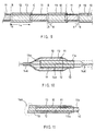
- Figure 9 is a central longitudinal sectional view of a second detector filament manufactured by means of the process in accordance with the invention, from which filament the detectors in accordance with the invention can be cut off.
- Figure 10 is a central axial sectional view of a version of the detector in accordance with the invention that is provided with a central wire.
- Figure 11 is a central axial sectional view of a coaxial detector construction in accordance with the invention.
- a continuous detector filament 100 is manufactured. Out of this detector filament 100, pieces are cut off in the transverse direction at the points R-R, which pieces constitute finished humidity detectors after making of possible connector parts.
- the humidity detector is processed onto a thin core filament 10, which acts as the substrate of the detector.
- the core filament 10 is by nature of circular section, and its diameter D s ⁇ 2r s is very little, being, as a rule, in the range of D s ⁇ 10 ⁇ m ... 2 mm, in radiosonde applications preferably in the range of D s ⁇ 50 ⁇ m ... 200 ⁇ m.
- bottom electrodes 11 Onto the core filament 10, in the areas F indicated in Fig. 1, bottom electrodes 11 have been applied, which also operate as contact parts.
- a polymer film 12 or equivalent Onto the bottom electrodes 11 and onto the parts of core filament 10 that remain free from said electrodes, a polymer film 12 or equivalent has been applied.
- the polymer film 12 operates as an active part in the detector capacitance C M .
- a surface electrode 13 has been applied, which is so thin that it is penetrable by moisture but is, however, electrically continuous.
- the detector filament 100 is cut off into pieces in the middle of the area F of the bottom electrodes 11, and in the areas E the polymer film 12 is removed so that connector areas are formed, to which the capacitance CM measurement wires are connected.
- a preferred exemplifying embodiment of the construction and dimensioning of the detector in accordance with the invention as well as the principle of operation of the detector will be described.
- the cylindrical capacitors C1 and C2 formed in the areas of both ends of the surface electrode 13 are connected in series when the detector capacitance C M is measured between the terminals 19.
- the active length 1 of the detector can be divided between the component capacitances C1 and C2 also in some way other than 1/2 and 1/2, i.e. the capacitances C1 and C2 can be of different magnitudes, compared with each other, which may be even an advantage, because in such a case a connection with the ground is not so disturbing.
- the thickness of the polymer film 12, i.e. r u -r s is typically a few micrometres.
- the detector capacitance C M can be dimensioned in accordance with the requirements of the particular application mainly by varying the axial measure 1.
- r s ⁇ 5 ⁇ m ... 1 mm preferably r s ⁇ 25 ⁇ m ... 100 ⁇ m r u ⁇ 5 ⁇ m ... 1 mm, preferably r u ⁇ 25 ⁇ m ... 100 ⁇ m 1 ⁇ 0.01 mm ... 100 mm, preferably 1 ⁇ 0.1 mm ... 40 mm L0 ⁇ 0.1 mm ... 100 mm, preferably L0 ⁇ 0.5 mm ... 5 mm L ⁇ 0.1 cm ... 20 cm, preferably L ⁇ 1 cm ... 10 cm
- the capacitance C M measured from the terminals 19 of the detector as shown in Figs. 3A and 3B is C M ⁇ 0.1 pF... 1000 pF, in radiosonde applications preferably C M ⁇ 2 pF ... 500 pF.
- the core filament 10 is a thin fibre made of glass or of some other insulation material alone.
- the core filament 10B in the core filament 10B, there is a resistor wire 14 that has been processed into the fibreglass core 10a, which resistor wire can be used as a heating resistor for the detector and/or for measurement of the temperature of the detector.
- the core 10C shown in Fig. 4C the core 10b is made of dielectric ceramic glass, which acts as the dielectric in the measurement of the temperature of the detector.
- the outside layer 16 consists of a glass coating or of some other insulating layer. With respect to the details of this construction, reference is made to the applicant's FI Patent Application No. 921449 of earlier date (filed April 1, 1992).
- the outer layer consists of glass or of some other insulating layer 16.
- a heating resistor wire 14 inside the glass core 10a there is a heating resistor wire 14, and outside the glass core 10 a resistor wire 14c has been wound for the purpose of measurement of the temperature.
- the functions of the resistor wires 14 and 14c may also be reversed.
- the outer layer 16 is a metallized layer or a glass coating.
- the wire 14c may be a suitable metal wire, such as a platinum wire.
- Figs. 4A to 4E it should still be emphasized that therein expressly core filaments 10;10B,10C;10D;10E are shown that operate as the substrate of the detector, onto which filaments the bottom electrodes 11, the polymer film 12, and the surface electrodes 13 are processed further.
- core filaments 10;10B,10C;10D;10E are shown that operate as the substrate of the detector, onto which filaments the bottom electrodes 11, the polymer film 12, and the surface electrodes 13 are processed further.
- Fig. 4C in which a dielectric ceramic glass is used as the core 10b
- FI Pat. Appl. No. 921449 In the construction shown in Fig.
- the measurement of the capacitance of the detector can be carried out between two opposite electrodes 15, as is described in said FI patent application, or between a cylindrical electrode 15 and a central electrode, which central electrode may also consist of a resistor wire 14. It is also possible to use various combinations and mixed constructions in accordance with Figs. 4B to 4E.
- Fig. 5 shows the production process of the core filament as a block diagram.
- the drawing of fibreglass is based on technology in itself known. So also the coating of a filament with glass, e.g., by means of a crucible with a hole, in which molten glass and the filament are drawn through the hole. It is also possible to coat two filaments with glass by means of a similar crucible so that the filaments remain separate inside the glass.
- the coating with glass can also be carried out by means of glass paste.
- the coating of fibreglass with metal can be carried out as vacuum evaporation or by means of conductive pastes.
- An insulating layer can be applied onto a metal-coated glass, e.g., by means of a perforated crucible with low-melting glass or by paste coating or by chemical methods, and some other insulating layer can be applied by submerging in a liquid.
- Figs. 6 to 8 some devices are illustrated schematically by whose means a core filament 10 produced in accordance with Fig. 5 can be provided with bottom electrodes 11 and be coated with an active polymer coating or equivalent.
- bottom electrodes 11 are vapour-deposited out of metal, which electrodes also operate as contact areas with the environment of the detector.
- the vacuum evaporating takes place, for example, so that the filament runs, in the way shown in Fig. 6, from the reel 28a onto the reel 28b stepwise as transfers of invariable length.
- the filament 100 is straight and runs through the evaporation mask 21.
- the function of the mask 21 is to protect the areas of the filament 10 that are not coated with metal.
- the filament 10 can be either rotated around its longitudinal axis in the mask 21, or several sources 30 of evaporation are used. In Fig.
- the reels 28a,28b are mounted on frame parts 27a and 27b, which are again mounted by means of horizontal shafts 26 and by means of axle journals 24a,24b fitted at the ends of the mask part 21 so that they can rotate around a horizontal axis, which horizontal axis coincides with the series of holes 25 in the mask 21 through which the filament 10 is passed from the starting reel 28a to the arrival reel 28b.
- the evaporation mask 21 is a number of pipes 22, which are placed at an invariable distance from one another.
- the filament 10 passes through the series of holes 25 in the pipe pieces 22, and the metallization is produced in the gaps in which the pipes 22 do not protect the filament.
- the metal evaporation takes place as vacuum evaporation from a source 30, so that the equipment 20 is placed inside an evaporation hood 29. Further, if necessary, the equipment 20 includes an optical detector as an aid for the mask alignment.
- the filament 10 produced in the step of detector manufacture shown in Figs. 6 and 7 is coated in the device 30 shown in Fig. 8 with a thin polymer layer, whose polymer PL operates as the humidity-sensitive insulation material of the capacitive detector that is formed, the permittivity of said material being a function of the amount of water absorbed by the film.
- the coating takes place by transferring the filament 10 from the reel 30a onto the reel 30b at an invariable speed. Between the reels 30a and 30b, the filament 10 is submerged in polymer PL in the basin 31, which contains a suitable solution concentration. In the bottom part of the basin 31, there is a guide roll or rod 32, over whose groove 32a the filament 10 is guided in the basin 31 first down and then up. Drying takes place in an oven 33 before the arrival reel 30b of the filament 10.
- the polymer PL can also be applied onto the filament by using a crucible through which the filament is drawn.
- the surface electrodes 13 are vapour-deposited in the same way as the bottom electrodes 11 were deposited in the step shown in Figs. 6 and 7. At the beginning, the location of the surface electrode 13 is aligned correctly between two bottom electrodes 11 and partly overlapping said bottom electrodes.
- the complete detector filament 100 is cut off at the points R-R, in the middle of the bottom electrodes 11, to make the detectors (Fig. 1).
- the detector filament 100 comprises detector elements
- various peeling processes, etchings, etc. are needed in order that the contact areas could be uncovered from the core.
- the peeling can take place, e.g., by etching, for example by means of a system similar to that shown in Fig. 8.
- the electric connecting of the detector takes place primarily by means of an electrically conductive adhesive.
- a shield preferably epoxies can be used.
- a number of different process steps may be needed additionally, for example treatments in an oven, chemical coatings, etchings, etc. They may be carried out by means of devices similar to those shown in Figs. 6 and 8.
- a heating wire 14 is, for example, platinum.
- the resistance of the heating resistor 14 is, as a rule, in the range of 1...5000 ohm, preferably 1...1000 ohm.
- the resistance of a wire that is used for measurement of temperature for example a platinum wire, is, as a rule, in the range of 1...3000 ohm, preferably 10...1000 ohm.
- the range of capacitance is typically of the same order as in humidity measurements.
- FIG. 9 an alternative detector filament is shown which has been manufactured by means of the method in accordance with the invention and out of which pieces of detector filament are cut off at the points R-R between the bottom electrode 11 and the surface electrode 13.
- the cylindrical bottom electrode 11 and the corresponding coaxial surface electrode 13 are placed one inside the other at one of their ends so that a cylindrical detector capacitance C is formed, in which a polymer film 12 or equivalent constitutes the dielectric.
- the detector capacitance C is connected by, at one end of the piece of detector filament, uncovering the bottom electrode 11 in the area K, and the connection to the surface electrode 13 takes place from the corresponding end of the piece of detector filament in the area K.
- a conductive core wire 14A to which the surface electrode 13 is connected electrically at one of its ends 13a.
- the point 13a and the cutting point placed at the vicinity of the core wire 14A are protected, e.g., by means of epoxy or equivalent.
- the connecting of the detector as shown in Fig. 10 takes place from one end 14A' of the core wire 14A and from the uncovered end 1 la of the bottom electrode 11.
- the active polymer film 12 or equivalent may also extend to outside the surface electrode 13.
- Fig. 11 shows a coaxial detector construction in which one end 16A of the piece of detector filament is protected from humidity by means of epoxy or equivalent.
- the parts 10,11,12 and 13 are coaxial with one another.
- the electric connecting takes place from the ends 11a and 13a of the electrodes 11 and 13.
- the connection area must be protected from humidity after the electric connecting by means of epoxy or equivalent.
- the core wire 14A if the core wire 14A is not needed for measurement of humidity, it can be used for heating the detector and/or for measurement of the temperature.
- 10 and 11 provide the advantage that the electric connecting of the detector can be carried out from one end of the detector alone, which facilitates the connecting of the detector to its environment.
- the connecting can be carried out, e.g., by means of an electrically conductive adhesive, in which case it is also possible to use adhesives that are, at the same time, etched through the dielectric layer 12, or said layer can be removed otherwise.
- the detector filament 100 can also be manufactured so that each piece of detector filament has pairs of bottom electrodes 11 of its own, between whose outer ends there is a free gap, at which the cutting (R-R) of the detector filament 100 is carried out.
- the bottom electrodes 11 and the surface electrodes are not necessarily unified cylindrical parts, but they may consist of patterns of other sorts and even of separate component patterns.
Landscapes
- General Physics & Mathematics (AREA)
- Engineering & Computer Science (AREA)
- Power Engineering (AREA)
- Physics & Mathematics (AREA)
- Chemical & Material Sciences (AREA)
- Life Sciences & Earth Sciences (AREA)
- Biochemistry (AREA)
- Chemical Kinetics & Catalysis (AREA)
- Electrochemistry (AREA)
- Health & Medical Sciences (AREA)
- Manufacturing & Machinery (AREA)
- Analytical Chemistry (AREA)
- Microelectronics & Electronic Packaging (AREA)
- General Health & Medical Sciences (AREA)
- Immunology (AREA)
- Pathology (AREA)
- Investigating Or Analyzing Materials By The Use Of Electric Means (AREA)
- Measuring Temperature Or Quantity Of Heat (AREA)
- Measurement Of Resistance Or Impedance (AREA)
- Investigating Or Analyzing Materials By The Use Of Fluid Adsorption Or Reactions (AREA)
Abstract
Description
- The invention concerns an impedance detector, in particular for radiosonde operation, which detector comprises a substrate made of an insulating material, onto which substrate the electrode and contact patterns necessary for the formation and connecting of the detector impedance have been applied, and in which detector, between the detector impedance electrodes, there is an active film, whose impedance values are a function of the physical quantity measured by means of the detector.
- The invention concerns a process for the manufacture of an impedance detector.
- In the prior art, a number of different electrically detected temperature and humidity detectors are known whose impedance changes as a function of the quantity to be measured. Such humidity detectors are known, e.g., from the US Patents Nos. 3,168,829 and 3,350,941 and from the applicant's Finnish Patent No. 48,229.
- The FI Patent No. 48,229 is related to the prior art concerned in the present invention, in which patent a capacitive humidity detector is described in which the dielectric insulating material is a polymer film whose permittivity is a function of the amount of water absorbed by the polymer film.
- As is known in the prior art, also for measurement of temperature, capacitive detectors are used, which are usually based on the fact that the permittivity of the insulating material between the capacitor plates is dependent on the temperature, in which case the capacitance detected from the terminals of the detector also depends on the temperature.
- In the detectors described above and also in other detectors based on change in impedance, undesirable phenomena occur, which include freezing and wetting of detectors, radiation error, slowness of the detectors, and hysteresis.
- In order to solve the problems discussed above, it is known from the prior art to provide said detectors with various mechanical shields. Also, attempts have been made to prevent the problems by providing the detectors with heating. Heated detectors require precise measurement of the temperature, which, for its part, produces problems of its own.
- With respect to the most recent development work carried out by the applicant, related to and closely connected with the present invention, reference is made to the following FI Patent Applications: No. 921449 (filed April 1, 1992), No. 933701 (filed August 23, 1993) and No. 933702 (filed August 23, 1993). The constructions and methods described in said applications can, where applicable, also be used in combination with the present invention.
- Moreover, in the prior-art humidity detectors, there has been need of further development in respect of the speed and accuracy of the detectors.
- The prior-art processes of manufacture of the detectors concerned have been demanding and consisted of a number of steps, in particular when a detector of maximum rapidity and accuracy has been aimed at, which usually requires very small size and precise measures of the constructions as well as good control of the various parameters in the processes of manufacture.
- The object of the present invention is further development both of the constructions and of the processes of manufacture of the prior-art impedance detectors, in particular of humidity detectors, so as to avoid the drawbacks mentioned above and to achieve the objectives stated above and those that will come out later.
- For these purposes, the detector in accordance with the invention is mainly characterized in that the substrate of the detector is an oblong core filament of an insulating material, onto and around which core filament said electrodes and said active film have been applied.
- On the other hand, the process of manufacture of said detectors in accordance with the invention is mainly characterized in that the process comprises a combination of the following steps (a), (b), (c), and (d) carried out in the given sequence:
- (a) onto the continuous core filament of insulating material, conductive bottom electrodes are vapour-deposited at a certain mutual axial distance from one another;
- (b) the continuous core filament obtained in the step (a) is coated with a material active in the measurement of impedance;
- (c) the continuous core filament obtained in the step (b) is coated with conductive surface electrodes, which are at least partly placed facing the gaps between said bottom electrodes and at least partly facing the bottom electrodes, and
- (d) the continuous detector filament obtained from the step (c) is cut off into pieces to make the impedance detectors.
- When the invention is applied as a capacitive humidity detector, the active material is an insulating material whose permittivity is a function of the amount of water absorbed by the insulating material.
- The impedance detector in accordance with the invention is characterized by wire-shaped form, small size, and little mass, which contributes to a detector of rapid time responses. The circular cross-sectional shape and the small size of the detector are also of advantage in the elimination of the freezing phenomenon. The little and favourable forms in the detector may already be sufficient to eliminate the problem of condensing and freezing of humidity, if necessary, together with a particular surface treatment. However, if these means are not sufficient, it is possible to integrate the detector in accordance with the invention with an efficient and rapid heating, in which case the measurement of temperature required in a humidity detector is precise and quick, because the inside and outside heat transfer properties of the detector are favourable. In such a case, measurement of temperature is used, in the way known from the prior art, as a starting value in the correction computing to eliminate the effect of heating that distorts the measurement of humidity.
- The detector construction that is most appropriate in each particular case depends on the mode of application of the detector in accordance with the invention. The detector can be used while heated constantly, periodically, or in some other way under controlled heating. The humidity detector in accordance with the invention is suitable for the use of efficient heating pulses of a duration of an order of just a millisecond, in which case quick measurement applications are possible. The measurement of temperature may take place as continuous or while alternating with measurement of humidity. With respect to cyclic heating and measurement of temperature, reference is made to the applicant's said FI Pat. Appl. 933702. It is also possible to accomplish the detector construction of the invention without heating and without measurement of temperature. Detector protection is not needed necessarily because of the small size of the detector. The shield constructions in themselves are centres of condensing and produce problems of humidity measurement.
- The detector construction in accordance with the invention permits the use of a continuous filament reel process in its manufacture and makes it easy to cut the filament into detector pieces and to use said detectors when provided with contacts at their ends. The core filament may be formed in a number of different ways. It is possible to use fibreglass alone, or in the interior of the glass there may be a heating resistor and/or a temperature measurement detector. For a temperature meter, a miniature thermistor is also suitable. The glass itself may also operate as the dielectric of a capacitive temperature detector, in which the core filament may be, at the same time, the heating resistor and one of the electrodes of the temperature measurement capacitance, whereas the metallization placed on the core constitutes the other electrode. As the basic material of the core, it is also possible to use some other suitable material besides glass, such as plastic.
- In the process of manufacture of the invention, onto the core filament, thin metal areas are vapour-deposited, which areas operate as a combined bottom and contact electrode when the detector is connected to its environment. Onto this construction, a thin polymer film or equivalent is processed. Onto this plastic film, the surface electrode is vapour-deposited, through which electrode moisture can penetrate into the polymer film. The surface electrode is preferably placed so that it is placed partly overlapping two successive bottom electrodes, and the part of the bottom electrode that is not covered by a surface electrode operates as a contact area when the detector is connected to its environment. Constructions of a different sort are also possible within the scope of the invention. The electrodes do not have to be unified faces and extend around the whole core, but they may consist of two or even more than two parts.
- In particular when manufactured by means of the process of the present invention, the detector in accordance with the invention becomes of low cost and easy to use. The detector in accordance with the invention is particularly suitable for use in radiosondes in measurement of relative humidity, but the humidity detector in accordance with the invention can also be applied to measurement of humidity in industry also under demanding conditions, and for weather monitoring or equivalent on the ground. In this connection, it should, however, be emphasized that the scope of the invention also includes other detectors, besides capacitive humidity detectors, such as resistive or capacitive temperature detectors and other, corresponding impedance detectors.
- Increased length and reduced thickness of the detector filament usually improve the construction of the humidity detector, because by these means the radiation error can be reduced, and an interfering adhesion of a water drop becomes more difficult and, even if a water drop should adhere, its relative effect of increasing the area of the surface electrode is reduced.
- If a heating wire and/or a temperature measurement wire is used inside the core filament in the detector filament in accordance with the invention, the gaps between the bottom electrodes should be dimensioned as little as possible so that the formation of a capacitance between the surface electrode and the wire placed in the core is minimized.
- In the following, the invention will be described in detail with reference to different exemplifying embodiments of the invention illustrated schematically in the figures in the accompanying drawing, the invention being by no means strictly confined to the details of said embodiments.
- Figure 1 is a schematic illustration of a detector filament manufactured by means of the process of the invention, from which filament the detectors in accordance with the invention are cut off.
- Figure 2A is a sectional view taken along the line A-A in Fig. 1.
- Figure 2B is a sectional view taken along the line B-B in Fig. 1.
- Figure 2C is a sectional view taken along the line C-C in Fig. 1.
- Figure 3A is a central longitudinal sectional view of a preferred detector construction in accordance with the invention.
- Figure 3B is a sectional view taken along the line B-B in Fig. 3A.
- Figures 4A,4B,4C,4D, and 4E are sectional views that illustrate alternative different constructions of the core filament that is used in the process of manufacture of the invention.
- Figure 5 is a block diagram illustration of different steps of manufacture of the core filament that is used in the detector in accordance with the invention.
- Figure 6 is a schematic illustration of a vapour-deposition device which is provided with reeling and rotating parts and which is intended for making the bottom electrodes in the process of manufacture in accordance with the invention.
- Figure 7A shows the mask part in the device as shown in Fig. 6.
- Figure 7B shows the same as Fig. 7A, seen in the direction of the guide opening of the mask part.
- Figure 8 is a schematic illustration of a continuous device based on reeling of a fibre and used in the process of manufacture in accordance with the invention, by means of which device the fibre filament provided with electrodes is coated with an active polymer film.
- Figure 9 is a central longitudinal sectional view of a second detector filament manufactured by means of the process in accordance with the invention, from which filament the detectors in accordance with the invention can be cut off.
- Figure 10 is a central axial sectional view of a version of the detector in accordance with the invention that is provided with a central wire.
- Figure 11 is a central axial sectional view of a coaxial detector construction in accordance with the invention.
- To begin with, mainly with reference to Figs. 1, 2A, 2B, and 2C, the principal features of the process of manufacture and of the detector in accordance with the invention will be described briefly.
- By means of the process in accordance with the invention, a
continuous detector filament 100 is manufactured. Out of thisdetector filament 100, pieces are cut off in the transverse direction at the points R-R, which pieces constitute finished humidity detectors after making of possible connector parts. The humidity detector is processed onto athin core filament 10, which acts as the substrate of the detector. Thecore filament 10 is by nature of circular section, and its diameter Ds ≈ 2rs is very little, being, as a rule, in the range of Ds ≈ 10 µm ... 2 mm, in radiosonde applications preferably in the range of Ds ≈ 50 µm ... 200 µm. Onto thecore filament 10, in the areas F indicated in Fig. 1,bottom electrodes 11 have been applied, which also operate as contact parts. Onto thebottom electrodes 11 and onto the parts ofcore filament 10 that remain free from said electrodes, apolymer film 12 or equivalent has been applied. Thepolymer film 12 operates as an active part in the detector capacitance CM. The permittivity of thepolymer film 12 is a function of the amount of water absorbed by thepolymer film 12, so that CM = f(RH). Onto thepolymer film 12, in the areas P, asurface electrode 13 has been applied, which is so thin that it is penetrable by moisture but is, however, electrically continuous. Thedetector filament 100 is cut off into pieces in the middle of the area F of thebottom electrodes 11, and in the areas E thepolymer film 12 is removed so that connector areas are formed, to which the capacitance CM measurement wires are connected. - According to Fig. 1, in the areas C₁ and C₂, between the
bottom electrode 11 and thesurface electrode 13, capacitances are formed, whose dielectric is thepolymer film 12. - In the following, with reference to Figs. 3A and 3B, a preferred exemplifying embodiment of the construction and dimensioning of the detector in accordance with the invention as well as the principle of operation of the detector will be described. The cylindrical capacitors C₁ and C₂ formed in the areas of both ends of the
surface electrode 13 are connected in series when the detector capacitance CM is measured between theterminals 19. With the measures given in Fig. 3A, C₁ = C₂ = C, in which case CM = C/2. In the construction of Fig. 3A, theactive length 1 of the detector can be divided between the component capacitances C₁ and C₂ also in some way other than 1/2 and 1/2, i.e. the capacitances C₁ and C₂ can be of different magnitudes, compared with each other, which may be even an advantage, because in such a case a connection with the ground is not so disturbing. - The capacitance C of a cylindrical capacitor is theoretically:

wherein
ε = permittivity of the medium
l = length
ru and rs = outer and inner radii - Typically, the dielectric constant εr (ε = εrεo) is in the range of εr ≈ 2...5. The thickness of the
polymer film 12, i.e. ru-rs, is typically a few micrometres. - In each detector application, the detector capacitance CM can be dimensioned in accordance with the requirements of the particular application mainly by varying the
axial measure 1. - In the following, the widest ranges of variation of different parameters in the dimensioning of a humidity detector and the preferable ranges of variation of same in radiosonde applications will be given.
rs ≈ 5 µm ... 1 mm, preferably rs ≈ 25 µm ... 100 µm
ru ≈ 5 µm ... 1 mm, preferably ru ≈ 25 µm ... 100 µm
1 ≈ 0.01 mm ... 100 mm, preferably 1 ≈ 0.1 mm ... 40 mm
L₀ ≈ 0.1 mm ... 100 mm, preferably L₀ ≈ 0.5 mm ... 5 mm
L ≈ 0.1 cm ... 20 cm, preferably L ≈ 1 cm ... 10 cm - The capacitance CM measured from the
terminals 19 of the detector as shown in Figs. 3A and 3B is CM ≈ 0.1 pF... 1000 pF, in radiosonde applications preferably CM ≈ 2 pF ... 500 pF. - In the following, with reference to Figs. 4A to 4E, different alternative constructions of the
core filament 10 which forms the substrate of the detector in accordance with the invention will be described. According to Fig. 4A, thecore filament 10 is a thin fibre made of glass or of some other insulation material alone. According to Fig. 4B, in the core filament 10B, there is aresistor wire 14 that has been processed into thefibreglass core 10a, which resistor wire can be used as a heating resistor for the detector and/or for measurement of the temperature of the detector. In thecore filament 10C shown in Fig. 4C, thecore 10b is made of dielectric ceramic glass, which acts as the dielectric in the measurement of the temperature of the detector. Theoutside layer 16 consists of a glass coating or of some other insulating layer. With respect to the details of this construction, reference is made to the applicant's FI Patent Application No. 921449 of earlier date (filed April 1, 1992). In the core filament 10D shown in Fig. 4D, in the interior of thefibreglass core 10a, two parallelheating resistor wires layer 16. - In the
core filament 10E shown in Fig. 4E, inside theglass core 10a there is aheating resistor wire 14, and outside theglass core 10 aresistor wire 14c has been wound for the purpose of measurement of the temperature. The functions of theresistor wires outer layer 16 is a metallized layer or a glass coating. Thewire 14c may be a suitable metal wire, such as a platinum wire. - With respect to Figs. 4A to 4E, it should still be emphasized that therein expressly
core filaments 10;10B,10C;10D;10E are shown that operate as the substrate of the detector, onto which filaments thebottom electrodes 11, thepolymer film 12, and thesurface electrodes 13 are processed further. With respect to the details of the construction and of the processes shown in Fig. 4C, in which a dielectric ceramic glass is used as thecore 10b, reference is made to the applicant's said FI Pat. Appl. No. 921449. In the construction shown in Fig. 4C, the measurement of the capacitance of the detector, which depends on the temperature, can be carried out between twoopposite electrodes 15, as is described in said FI patent application, or between acylindrical electrode 15 and a central electrode, which central electrode may also consist of aresistor wire 14. It is also possible to use various combinations and mixed constructions in accordance with Figs. 4B to 4E. - Fig. 5 shows the production process of the core filament as a block diagram. The drawing of fibreglass is based on technology in itself known. So also the coating of a filament with glass, e.g., by means of a crucible with a hole, in which molten glass and the filament are drawn through the hole. It is also possible to coat two filaments with glass by means of a similar crucible so that the filaments remain separate inside the glass. The coating with glass can also be carried out by means of glass paste. The coating of fibreglass with metal can be carried out as vacuum evaporation or by means of conductive pastes. An insulating layer can be applied onto a metal-coated glass, e.g., by means of a perforated crucible with low-melting glass or by paste coating or by chemical methods, and some other insulating layer can be applied by submerging in a liquid.
- In Figs. 6 to 8, some devices are illustrated schematically by whose means a
core filament 10 produced in accordance with Fig. 5 can be provided withbottom electrodes 11 and be coated with an active polymer coating or equivalent. - Onto the
core filament 10,bottom electrodes 11 are vapour-deposited out of metal, which electrodes also operate as contact areas with the environment of the detector. The vacuum evaporating takes place, for example, so that the filament runs, in the way shown in Fig. 6, from the reel 28a onto the reel 28b stepwise as transfers of invariable length. Between the reels 28a and 28b, thefilament 100 is straight and runs through theevaporation mask 21. The function of themask 21 is to protect the areas of thefilament 10 that are not coated with metal. In order that the metallization could be applied around thefilament 10, thefilament 10 can be either rotated around its longitudinal axis in themask 21, orseveral sources 30 of evaporation are used. In Fig. 6, for said rotation of thefilament 10, the reels 28a,28b are mounted onframe parts 27a and 27b, which are again mounted by means ofhorizontal shafts 26 and by means ofaxle journals mask part 21 so that they can rotate around a horizontal axis, which horizontal axis coincides with the series ofholes 25 in themask 21 through which thefilament 10 is passed from the starting reel 28a to the arrival reel 28b. In principle, theevaporation mask 21 is a number ofpipes 22, which are placed at an invariable distance from one another. Thefilament 10 passes through the series ofholes 25 in thepipe pieces 22, and the metallization is produced in the gaps in which thepipes 22 do not protect the filament. The metal evaporation takes place as vacuum evaporation from asource 30, so that theequipment 20 is placed inside anevaporation hood 29. Further, if necessary, theequipment 20 includes an optical detector as an aid for the mask alignment. - The
filament 10 produced in the step of detector manufacture shown in Figs. 6 and 7 is coated in thedevice 30 shown in Fig. 8 with a thin polymer layer, whose polymer PL operates as the humidity-sensitive insulation material of the capacitive detector that is formed, the permittivity of said material being a function of the amount of water absorbed by the film. The coating takes place by transferring thefilament 10 from the reel 30a onto the reel 30b at an invariable speed. Between the reels 30a and 30b, thefilament 10 is submerged in polymer PL in thebasin 31, which contains a suitable solution concentration. In the bottom part of thebasin 31, there is a guide roll orrod 32, over whosegroove 32a thefilament 10 is guided in thebasin 31 first down and then up. Drying takes place in anoven 33 before the arrival reel 30b of thefilament 10. The polymer PL can also be applied onto the filament by using a crucible through which the filament is drawn. - Onto the
filament 10 obtained in the step of manufacture shown in Fig. 8, thesurface electrodes 13 are vapour-deposited in the same way as thebottom electrodes 11 were deposited in the step shown in Figs. 6 and 7. At the beginning, the location of thesurface electrode 13 is aligned correctly between twobottom electrodes 11 and partly overlapping said bottom electrodes. - After the latter step, the
complete detector filament 100 is cut off at the points R-R, in the middle of thebottom electrodes 11, to make the detectors (Fig. 1). If thedetector filament 100 comprises detector elements, various peeling processes, etchings, etc. are needed in order that the contact areas could be uncovered from the core. The peeling can take place, e.g., by etching, for example by means of a system similar to that shown in Fig. 8. The electric connecting of the detector takes place primarily by means of an electrically conductive adhesive. As a shield, preferably epoxies can be used. In the making of the detector, a number of different process steps may be needed additionally, for example treatments in an oven, chemical coatings, etchings, etc. They may be carried out by means of devices similar to those shown in Figs. 6 and 8. - Well suitable for the material of a
heating wire 14 is, for example, platinum. The resistance of theheating resistor 14 is, as a rule, in the range of 1...5000 ohm, preferably 1...1000 ohm. The resistance of a wire that is used for measurement of temperature, for example a platinum wire, is, as a rule, in the range of 1...3000 ohm, preferably 10...1000 ohm. When capacitive temperature measurement is used, the range of capacitance is typically of the same order as in humidity measurements. - In Fig. 9, an alternative detector filament is shown which has been manufactured by means of the method in accordance with the invention and out of which pieces of detector filament are cut off at the points R-R between the
bottom electrode 11 and thesurface electrode 13. Thecylindrical bottom electrode 11 and the correspondingcoaxial surface electrode 13 are placed one inside the other at one of their ends so that a cylindrical detector capacitance C is formed, in which apolymer film 12 or equivalent constitutes the dielectric. The detector capacitance C is connected by, at one end of the piece of detector filament, uncovering thebottom electrode 11 in the area K, and the connection to thesurface electrode 13 takes place from the corresponding end of the piece of detector filament in the area K. - In Fig. 10, inside the
filament 10 of insulating material, there is aconductive core wire 14A, to which thesurface electrode 13 is connected electrically at one of its ends 13a. The point 13a and the cutting point placed at the vicinity of thecore wire 14A are protected, e.g., by means of epoxy or equivalent. The connecting of the detector as shown in Fig. 10 takes place from oneend 14A' of thecore wire 14A and from theuncovered end 1 la of thebottom electrode 11. Theactive polymer film 12 or equivalent may also extend to outside thesurface electrode 13. - Fig. 11 shows a coaxial detector construction in which one
end 16A of the piece of detector filament is protected from humidity by means of epoxy or equivalent. On thecore 10, there is acylindrical bottom electrode 11, and on said electrode a cylindricalactive film 12, and on the film acylindrical surface electrode 13. Theparts ends 11a and 13a of theelectrodes core wire 14A is not needed for measurement of humidity, it can be used for heating the detector and/or for measurement of the temperature. The constructions shown in Figs. 10 and 11 provide the advantage that the electric connecting of the detector can be carried out from one end of the detector alone, which facilitates the connecting of the detector to its environment. The connecting can be carried out, e.g., by means of an electrically conductive adhesive, in which case it is also possible to use adhesives that are, at the same time, etched through thedielectric layer 12, or said layer can be removed otherwise. - Above, some exemplifying embodiments have been described, which are preferable according to the present experience and estimate. However, it should be emphasized that the idea of the invention can also be carried into effect in a number of manners differing from the exemplifying embodiments given above. The
detector filament 100 can also be manufactured so that each piece of detector filament has pairs ofbottom electrodes 11 of its own, between whose outer ends there is a free gap, at which the cutting (R-R) of thedetector filament 100 is carried out. Also, thebottom electrodes 11 and the surface electrodes are not necessarily unified cylindrical parts, but they may consist of patterns of other sorts and even of separate component patterns. - In the following, the patent claims will be given, and the various details of the invention may show variation within the scope of the inventive idea defined in said claims and differ from what has been stated above by way of example only.
Claims (15)
- Impedance detector, in particular for radiosonde operation, which detector comprises a substrate (10...10E) made of an insulating material, onto which substrate the electrode and contact patterns (11,11a,13) necessary for the formation and connecting of the detector impedance have been applied, and in which detector, between the detector impedance electrodes (11,13), there is an active film (12), whose impedance values are a function of the physical quantity- measured by means of the detector, characterized in that the substrate of the detector is an oblong core filament (10;10B;10C;10D;10E) of an insulating material, onto and around which core filament said electrodes (11,13) and said active insulating film (12) have been applied.
- Capacitive humidity detector as claimed in claim 1, wherein, between the detector capacitance electrodes, there is an active insulating film (12), whose permittivity (ε) is a function of the amount of water absorbed by the insulating film (12), characterized in that said electrodes (11,13) and said active insulating film (12) have been applied onto and around the core filament (10) of insulating material.
- Detector as claimed in claim 1 or 2, characterized in that, in a circular section of said core filament (10...15), the detector is substantially circularly symmetric and, in relation to the longitudinal centre axis of the detector filament (10), substantially coaxial.
- Detector as claimed in any of the claims 1 to 3, characterized in that, on the core filament (10), there are cylindrical bottom electrodes (11), which are placed at a certain distance (L₀) from one another in the longitudinal direction of the core filament so that, on said bottom electrodes (11), there is an insulating film (12), and that, on said insulating film (12), there is a cylindrical surface electrode (13), which is so thin that it is penetrable by humidity but is electrically continuous, that said bottom electrodes (11) and said surface electrode (13) extend so that they overlap each other partially on a certain axial dimension (1), that the capacitance (CM) to be measured is formed from a connection in series of the two cylindrical capacitances (C₁,C₂) between the bottom electrodes (11) and the surface electrode (13), and that the capacitance (CM) to be measured can be measured between said bottom electrodes (11), preferably between their end areas (11a).
- Detector as claimed in any of the claims 1 to 4, characterized in that, in the interior of the core filament (10B;10C;10D;10E), one or several resistor wires (14;14a,14b) are fitted, which can be used for electric heating of the detector and/or for measurement of the detector temperature based on the dependence of the resistance of said resistor wire (14;14a,14b) on temperature.
- Detector as claimed in any of the claims 1 to 5, characterized in that, on and around the core filament (10E), there is a winding resistor wire that can be used for heating and/or for measurement of temperature (Fig. 4E).
- Detector as claimed in any of the claims 1 to 6, characterized in that the core filament (10C) of the detector is made of dielectric ceramic glass, which operates as the dielectric for the measurement of the temperature of the detector, that, in connection with said core (10B), contact patterns or equivalent are provided, between which the temperature-dependent capacitance can be measured, and that the outer layer (16) of the core filament (10C) is a glass layer and/or any other insulating layer (Fig. 4C).
- Process for the manufacture of an impedance detector, characterized in that the process comprises a combination of the following steps (a), (b), (c), and (d) carried out in the given sequence:(a) onto the continuous core filament (10;10B;10C;10D;10E) of insulating material, conductive bottom electrodes (11) are vapour-deposited at a certain mutual axial distance (L₀) from one another;(b) the continuous core filament (10) obtained in the step (a) is coated with a material active in the measurement of impedance;(c) the continuous core filament (10) obtained in the step (b) is coated with conductive surface electrodes (13), which are placed at least partly facing the gaps (L₀) between said bottom electrodes (11) and at least partly facing the bottom electrodes (11), and(d) the continuous detector filament (100) obtained from the step (c) is cut off into pieces to make the impedance detectors.
- Process as claimed in claim 8, characterized in that said steps (a) and (b) are carried out by reeling the core filament (10) from a starting reel (28a,30a) onto an arrival reel (28b,30b).
- Process as claimed in claim 8 or 9, characterized in that the continuous detector filament (10) obtained from the step (c) is cut off into detectors at the bottom electrodes (11), preferably substantially at their middle, and that contact areas (11a) are uncovered in a peeling or etching process at the ends of said bottom electrodes (11), and electric connectors (19) of the detector are connected to said contact areas, preferably by means of an electrically conductive adhesive.
- Process as claimed in claim 8 or 9, characterized in that the continuous detector filament (10) is cut off into detectors at the gaps between the bottom electrodes (11) and the surface electrodes (13) free from said electrodes (11,13).
- Process of manufacture as claimed in any of the claims 8 to 11, characterized in that the making of the bottom electrodes (11) in accordance with the step (a) takes place so that the core filament (10) is reeled from a starting reel (28a) onto an arrival reel (28b) stepwise through a mask part (21).
- Process of manufacture as claimed in any of the claims 8 to 11, charac terized in that the coating in accordance with the step (b) of the core filament (10) that is provided with bottom electrodes (11) takes place so that the core filament (10) is passed from a starting reel (30a) onto an arrival reel (30b) through a basin (31) that contains a coating-agent solution (PL) or melt or through an equivalent crucible for drawing through, preferably at an invariable speed, whereupon the coated core filament (10) is, if necessary, passed through a drying step (33) placed before the arrival reel (30b) (Fig. 8).
- Process of manufacture as claimed in any of the claims 8 to 13, characterized in that the continuous core filament (10) that is used in the step (a) is manufactured by in its interior and/or on said filament placing a resistor wire (14; 14A,14B;14C), and that the core filament that has been manufactured in the steps mentioned above is coated with a layer of insulating material (16).
- Process of manufacture as claimed in any of the claims 8 to 14, characterized in that, in the process, the glass core (10b) is made of dielectric glass, which is fitted as the dielectric of the capacitor used in capacitive measurement of temperature in the detector.
Applications Claiming Priority (2)
| Application Number | Priority Date | Filing Date | Title |
|---|---|---|---|
| FI934266A FI98567C (en) | 1993-09-29 | 1993-09-29 | Impedance sensor, especially for radio probe use, as well as a method for producing a sensor |
| FI934266 | 1993-09-29 |
Publications (2)
| Publication Number | Publication Date |
|---|---|
| EP0647833A1 true EP0647833A1 (en) | 1995-04-12 |
| EP0647833B1 EP0647833B1 (en) | 1999-07-14 |
Family
ID=8538686
Family Applications (1)
| Application Number | Title | Priority Date | Filing Date |
|---|---|---|---|
| EP94850150A Expired - Lifetime EP0647833B1 (en) | 1993-09-29 | 1994-09-05 | Capacitive humidity sensor, in particular for radiosonde operation, as well as a process for the manufacture of a detector |
Country Status (5)
| Country | Link |
|---|---|
| US (2) | US5553495A (en) |
| EP (1) | EP0647833B1 (en) |
| JP (1) | JP3625873B2 (en) |
| DE (1) | DE69419471T2 (en) |
| FI (1) | FI98567C (en) |
Cited By (2)
| Publication number | Priority date | Publication date | Assignee | Title |
|---|---|---|---|---|
| EP1736054A2 (en) * | 2005-06-22 | 2006-12-27 | ANGELO PO GRANDI CUCINE S.p.A. | System for controlling humidity |
| WO2009118453A2 (en) * | 2008-03-26 | 2009-10-01 | Elsi Technologies Oy | Adaptor component for a measuring system |
Families Citing this family (12)
| Publication number | Priority date | Publication date | Assignee | Title |
|---|---|---|---|---|
| FI98567C (en) * | 1993-09-29 | 1997-07-10 | Vaisala Oy | Impedance sensor, especially for radio probe use, as well as a method for producing a sensor |
| FI98568C (en) * | 1994-12-28 | 1997-07-10 | Vaisala Oy | Electronically expressed impedance sensor for measuring physical quantities, in particular temperature or humidity, and method of manufacturing such sensors |
| US6046091A (en) * | 1997-06-10 | 2000-04-04 | Usf Filtration And Seperations Group, Inc. | Capacitor and method of making |
| WO1998057341A1 (en) * | 1997-06-10 | 1998-12-17 | Usf Filtration And Separations Group, Inc. | Capacitor and method of making |
| US6634213B1 (en) * | 2000-02-18 | 2003-10-21 | Honeywell International Inc. | Permeable protective coating for a single-chip hydrogen sensor |
| JP4566784B2 (en) * | 2005-02-24 | 2010-10-20 | 株式会社デンソー | Humidity sensor device |
| US7518380B2 (en) * | 2005-05-17 | 2009-04-14 | Honeywell International Inc. | Chemical impedance detectors for fluid analyzers |
| KR101787189B1 (en) | 2015-06-29 | 2017-11-16 | 한국표준과학연구원 | Radiosonde having a plurality of temperature sensors and method for measuring temperature using the same and system and method for correcting thereof |
| FI127193B (en) * | 2016-12-22 | 2018-01-31 | Vaisala Oyj | Method associated with a radiosonde and system |
| DE102017202631A1 (en) * | 2017-02-17 | 2018-08-23 | Leoni Kabel Gmbh | Monitoring system and cables |
| WO2019017045A1 (en) * | 2017-07-20 | 2019-01-24 | アルプス電気株式会社 | Temperature sensor |
| CN111351596B (en) * | 2020-04-21 | 2021-06-04 | 上海无线电设备研究所 | Capacitance type sensor for measuring temperature |
Citations (5)
| Publication number | Priority date | Publication date | Assignee | Title |
|---|---|---|---|---|
| US2011710A (en) * | 1928-08-18 | 1935-08-20 | Nat Aniline & Chem Co Inc | Apparatus for measuring temperature |
| US3443293A (en) * | 1965-09-03 | 1969-05-13 | Sho Masujima | Method of manufacturing capacitors |
| US4347550A (en) * | 1977-12-22 | 1982-08-31 | Peter Rockliff | Sensor detector element for an electrical hygrometer |
| JPS57201827A (en) * | 1981-06-05 | 1982-12-10 | Matsushita Electric Ind Co Ltd | Temperature detecting device |
| GB2234820A (en) * | 1989-08-11 | 1991-02-13 | Vaisala Oy | capacitive element and method for its manufacture |
Family Cites Families (19)
| Publication number | Priority date | Publication date | Assignee | Title |
|---|---|---|---|---|
| US3075385A (en) * | 1960-12-15 | 1963-01-29 | Clifford M Stover | Hygrometer |
| US3168829A (en) * | 1961-10-05 | 1965-02-09 | Honeywell Inc | Control apparatus |
| US3350941A (en) * | 1965-05-20 | 1967-11-07 | Johnson Service Co | Humidity sensing element |
| DE1598446A1 (en) * | 1966-05-03 | 1969-06-26 | Hoechst Ag | Humidity sensor |
| FI48229C (en) * | 1972-10-12 | 1974-07-10 | Vaisala Oy | Capacitive humidity sensor and manufacturing process for the same. |
| SU597955A1 (en) * | 1975-06-02 | 1978-03-15 | Институт Экспериментальной Метеорологии | Moisture sensor |
| JPS58135945A (en) * | 1982-02-08 | 1983-08-12 | Kakubari Shigeru | Humidity measuring element |
| US5018048A (en) * | 1983-12-19 | 1991-05-21 | Spectrum Control, Inc. | Miniaturized monolithic multi-layer capacitor and apparatus and method for making |
| NL8401320A (en) * | 1984-04-25 | 1985-11-18 | Philips Nv | METHOD AND APPARATUS FOR MANUFACTURING MULTILAYER CERAMIC CAPACITORS. |
| JPH0517650Y2 (en) * | 1986-01-31 | 1993-05-12 | ||
| US4793181A (en) * | 1987-06-02 | 1988-12-27 | Djorup Robert Sonny | Constant temperature sorption hygrometer |
| JPH01167646A (en) * | 1987-12-23 | 1989-07-03 | Tekune Yoko:Kk | Electric capacity type hygrometer |
| FI85770C (en) * | 1990-02-21 | 1992-05-25 | Vaisala Oy | Procedure in connection with impedance sensors in radio probes |
| US5036704A (en) * | 1990-03-23 | 1991-08-06 | Gas Research Institute | Moisture sensor |
| US5179773A (en) * | 1991-08-30 | 1993-01-19 | Bmc Technology Corporation | Process of manufacturing multilayer ceramic capacitors |
| DE4132232A1 (en) * | 1991-09-27 | 1993-04-01 | Bosch Gmbh Robert | Capacitive sensor mfr. using monocrystal wafer - sawing through tri-layer arrangement of conductive plates and wafer which are bonded, glued, welded or soldered together |
| DE4140831A1 (en) * | 1991-12-11 | 1993-07-08 | Berghof Sensorik Gmbh | HUMIDITY SENSOR |
| FI96640C (en) * | 1993-08-23 | 1996-07-25 | Vaisala Oy | Method for measuring relative humidity, especially in radiosondes |
| FI98567C (en) * | 1993-09-29 | 1997-07-10 | Vaisala Oy | Impedance sensor, especially for radio probe use, as well as a method for producing a sensor |
-
1993
- 1993-09-29 FI FI934266A patent/FI98567C/en active
-
1994
- 1994-09-05 EP EP94850150A patent/EP0647833B1/en not_active Expired - Lifetime
- 1994-09-05 DE DE69419471T patent/DE69419471T2/en not_active Expired - Fee Related
- 1994-09-16 US US08/307,057 patent/US5553495A/en not_active Expired - Lifetime
- 1994-09-29 JP JP25944394A patent/JP3625873B2/en not_active Expired - Fee Related
-
1995
- 1995-03-28 US US08/412,142 patent/US5557042A/en not_active Expired - Lifetime
Patent Citations (5)
| Publication number | Priority date | Publication date | Assignee | Title |
|---|---|---|---|---|
| US2011710A (en) * | 1928-08-18 | 1935-08-20 | Nat Aniline & Chem Co Inc | Apparatus for measuring temperature |
| US3443293A (en) * | 1965-09-03 | 1969-05-13 | Sho Masujima | Method of manufacturing capacitors |
| US4347550A (en) * | 1977-12-22 | 1982-08-31 | Peter Rockliff | Sensor detector element for an electrical hygrometer |
| JPS57201827A (en) * | 1981-06-05 | 1982-12-10 | Matsushita Electric Ind Co Ltd | Temperature detecting device |
| GB2234820A (en) * | 1989-08-11 | 1991-02-13 | Vaisala Oy | capacitive element and method for its manufacture |
Non-Patent Citations (1)
| Title |
|---|
| PATENT ABSTRACTS OF JAPAN vol. 7, no. 54 (P - 180)<1199> 4 March 1983 (1983-03-04) * |
Cited By (5)
| Publication number | Priority date | Publication date | Assignee | Title |
|---|---|---|---|---|
| EP1736054A2 (en) * | 2005-06-22 | 2006-12-27 | ANGELO PO GRANDI CUCINE S.p.A. | System for controlling humidity |
| EP1736054A3 (en) * | 2005-06-22 | 2011-09-21 | ANGELO PO GRANDI CUCINE S.p.A. | System for controlling humidity |
| WO2009118453A2 (en) * | 2008-03-26 | 2009-10-01 | Elsi Technologies Oy | Adaptor component for a measuring system |
| WO2009118453A3 (en) * | 2008-03-26 | 2009-11-19 | Elsi Technologies Oy | Adaptor component for a measuring system |
| US9151641B2 (en) | 2008-03-26 | 2015-10-06 | Elsi Technologies Oy | Adaptor component for a measuring system |
Also Published As
| Publication number | Publication date |
|---|---|
| DE69419471T2 (en) | 1999-10-28 |
| EP0647833B1 (en) | 1999-07-14 |
| DE69419471D1 (en) | 1999-08-19 |
| FI98567C (en) | 1997-07-10 |
| US5557042A (en) | 1996-09-17 |
| FI934266A (en) | 1995-03-30 |
| JP3625873B2 (en) | 2005-03-02 |
| FI934266A0 (en) | 1993-09-29 |
| US5553495A (en) | 1996-09-10 |
| JPH07198654A (en) | 1995-08-01 |
| FI98567B (en) | 1997-03-27 |
Similar Documents
| Publication | Publication Date | Title |
|---|---|---|
| US5553495A (en) | Impedance detector, in particular for radiosonde operation and process for manufacture of an impedance detector | |
| CA2092609C (en) | Electrical impedance detector for measurement of physical quantities | |
| FI72393C (en) | FOERFARANDE FOER FRAMSTAELLNING AV EN TUNT ISOLERAD KAPACITIV HYGROMETER OCH ENLIGT DETTA FOERFARANDE FRAMSTAELLD HYGROMETER. | |
| FI71998C (en) | Capacitive hygrometer, where in used capacitor and method for making capacitor. | |
| KR101527707B1 (en) | Sensor for mesuring concentration of hydrogen ion and method for manufacturing the same | |
| US4515653A (en) | Method for production of a moisture sensor | |
| CH632341A5 (en) | MEASURING PROBE. | |
| EP0645606B1 (en) | Electrically detected impedance detector for the measurement of physical quantities, in particular of temperature or humidity, and process for the manufacture of said detectors | |
| US4481813A (en) | Dew sensor | |
| US5386195A (en) | Method and apparatus for monitoring an electrical property of a conductive coating | |
| KR101148630B1 (en) | Structure of water level sensor | |
| FI98568C (en) | Electronically expressed impedance sensor for measuring physical quantities, in particular temperature or humidity, and method of manufacturing such sensors | |
| US4462020A (en) | Miniature resistive temperature detector and method of fabrication | |
| JP2943028B2 (en) | pH measuring electrode and method for producing the same | |
| JPS61237044A (en) | Moisture detection element and manufacture thereof | |
| RU2826793C1 (en) | Gas moisture sensor | |
| CN114171315B (en) | Inductance measuring system and method for coil winding and coil winding method | |
| GB1570054A (en) | Sensor or detector element for an electrical hygrometer | |
| JPH0650925A (en) | Manufacture of humidity sensor | |
| JP2824281B2 (en) | Method and apparatus for measuring insulation coating thickness of coated wire for bonding | |
| JPH03140858A (en) | Ion electrode | |
| SU787971A1 (en) | Apparatus for determining moisture penetration | |
| SU1691781A1 (en) | Transducer for measuring specific capacitance of foil | |
| JPH02297038A (en) | Method and apparatus for monitoring covering property of optical fiber |
Legal Events
| Date | Code | Title | Description |
|---|---|---|---|
| PUAI | Public reference made under article 153(3) epc to a published international application that has entered the european phase |
Free format text: ORIGINAL CODE: 0009012 |
|
| AK | Designated contracting states |
Kind code of ref document: A1 Designated state(s): CH DE DK ES FR GB IT LI SE |
|
| 17P | Request for examination filed |
Effective date: 19950421 |
|
| 17Q | First examination report despatched |
Effective date: 19961028 |
|
| GRAG | Despatch of communication of intention to grant |
Free format text: ORIGINAL CODE: EPIDOS AGRA |
|
| GRAG | Despatch of communication of intention to grant |
Free format text: ORIGINAL CODE: EPIDOS AGRA |
|
| GRAH | Despatch of communication of intention to grant a patent |
Free format text: ORIGINAL CODE: EPIDOS IGRA |
|
| GRAH | Despatch of communication of intention to grant a patent |
Free format text: ORIGINAL CODE: EPIDOS IGRA |
|
| GRAA | (expected) grant |
Free format text: ORIGINAL CODE: 0009210 |
|
| AK | Designated contracting states |
Kind code of ref document: B1 Designated state(s): CH DE DK ES FR GB IT LI SE |
|
| PG25 | Lapsed in a contracting state [announced via postgrant information from national office to epo] |
Ref country code: SE Free format text: THE PATENT HAS BEEN ANNULLED BY A DECISION OF A NATIONAL AUTHORITY Effective date: 19990714 Ref country code: LI Free format text: LAPSE BECAUSE OF FAILURE TO SUBMIT A TRANSLATION OF THE DESCRIPTION OR TO PAY THE FEE WITHIN THE PRESCRIBED TIME-LIMIT Effective date: 19990714 Ref country code: ES Free format text: THE PATENT HAS BEEN ANNULLED BY A DECISION OF A NATIONAL AUTHORITY Effective date: 19990714 Ref country code: CH Free format text: LAPSE BECAUSE OF FAILURE TO SUBMIT A TRANSLATION OF THE DESCRIPTION OR TO PAY THE FEE WITHIN THE PRESCRIBED TIME-LIMIT Effective date: 19990714 |
|
| REG | Reference to a national code |
Ref country code: CH Ref legal event code: EP |
|
| REF | Corresponds to: |
Ref document number: 69419471 Country of ref document: DE Date of ref document: 19990819 |
|
| ITF | It: translation for a ep patent filed | ||
| PG25 | Lapsed in a contracting state [announced via postgrant information from national office to epo] |
Ref country code: DK Free format text: LAPSE BECAUSE OF FAILURE TO SUBMIT A TRANSLATION OF THE DESCRIPTION OR TO PAY THE FEE WITHIN THE PRESCRIBED TIME-LIMIT Effective date: 19991014 |
|
| ET | Fr: translation filed | ||
| REG | Reference to a national code |
Ref country code: CH Ref legal event code: PL |
|
| PLBE | No opposition filed within time limit |
Free format text: ORIGINAL CODE: 0009261 |
|
| STAA | Information on the status of an ep patent application or granted ep patent |
Free format text: STATUS: NO OPPOSITION FILED WITHIN TIME LIMIT |
|
| 26N | No opposition filed | ||
| REG | Reference to a national code |
Ref country code: GB Ref legal event code: IF02 |
|
| PGFP | Annual fee paid to national office [announced via postgrant information from national office to epo] |
Ref country code: IT Payment date: 20080926 Year of fee payment: 15 Ref country code: FR Payment date: 20080828 Year of fee payment: 15 |
|
| PGFP | Annual fee paid to national office [announced via postgrant information from national office to epo] |
Ref country code: GB Payment date: 20080910 Year of fee payment: 15 |
|
| PGFP | Annual fee paid to national office [announced via postgrant information from national office to epo] |
Ref country code: DE Payment date: 20081001 Year of fee payment: 15 |
|
| GBPC | Gb: european patent ceased through non-payment of renewal fee |
Effective date: 20090905 |
|
| REG | Reference to a national code |
Ref country code: FR Ref legal event code: ST Effective date: 20100531 |
|
| PG25 | Lapsed in a contracting state [announced via postgrant information from national office to epo] |
Ref country code: FR Free format text: LAPSE BECAUSE OF NON-PAYMENT OF DUE FEES Effective date: 20090930 Ref country code: DE Free format text: LAPSE BECAUSE OF NON-PAYMENT OF DUE FEES Effective date: 20100401 |
|
| PG25 | Lapsed in a contracting state [announced via postgrant information from national office to epo] |
Ref country code: GB Free format text: LAPSE BECAUSE OF NON-PAYMENT OF DUE FEES Effective date: 20090905 |
|
| PG25 | Lapsed in a contracting state [announced via postgrant information from national office to epo] |
Ref country code: IT Free format text: LAPSE BECAUSE OF NON-PAYMENT OF DUE FEES Effective date: 20090905 |