EP0647779A1 - Exhaust gas recirculation device for an internal combustion engine - Google Patents
Exhaust gas recirculation device for an internal combustion engine Download PDFInfo
- Publication number
- EP0647779A1 EP0647779A1 EP94402241A EP94402241A EP0647779A1 EP 0647779 A1 EP0647779 A1 EP 0647779A1 EP 94402241 A EP94402241 A EP 94402241A EP 94402241 A EP94402241 A EP 94402241A EP 0647779 A1 EP0647779 A1 EP 0647779A1
- Authority
- EP
- European Patent Office
- Prior art keywords
- exhaust gas
- sleeve
- gas recirculation
- intake manifold
- recirculation device
- Prior art date
- Legal status (The legal status is an assumption and is not a legal conclusion. Google has not performed a legal analysis and makes no representation as to the accuracy of the status listed.)
- Withdrawn
Links
Images
Classifications
-
- F—MECHANICAL ENGINEERING; LIGHTING; HEATING; WEAPONS; BLASTING
- F16—ENGINEERING ELEMENTS AND UNITS; GENERAL MEASURES FOR PRODUCING AND MAINTAINING EFFECTIVE FUNCTIONING OF MACHINES OR INSTALLATIONS; THERMAL INSULATION IN GENERAL
- F16L—PIPES; JOINTS OR FITTINGS FOR PIPES; SUPPORTS FOR PIPES, CABLES OR PROTECTIVE TUBING; MEANS FOR THERMAL INSULATION IN GENERAL
- F16L27/00—Adjustable joints, Joints allowing movement
- F16L27/10—Adjustable joints, Joints allowing movement comprising a flexible connection only, e.g. for damping vibrations
- F16L27/107—Adjustable joints, Joints allowing movement comprising a flexible connection only, e.g. for damping vibrations the ends of the pipe being interconnected by a flexible sleeve
- F16L27/108—Adjustable joints, Joints allowing movement comprising a flexible connection only, e.g. for damping vibrations the ends of the pipe being interconnected by a flexible sleeve the sleeve having the form of a bellows with only one corrugation
-
- F—MECHANICAL ENGINEERING; LIGHTING; HEATING; WEAPONS; BLASTING
- F02—COMBUSTION ENGINES; HOT-GAS OR COMBUSTION-PRODUCT ENGINE PLANTS
- F02M—SUPPLYING COMBUSTION ENGINES IN GENERAL WITH COMBUSTIBLE MIXTURES OR CONSTITUENTS THEREOF
- F02M26/00—Engine-pertinent apparatus for adding exhaust gases to combustion-air, main fuel or fuel-air mixture, e.g. by exhaust gas recirculation [EGR] systems
- F02M26/11—Manufacture or assembly of EGR systems; Materials or coatings specially adapted for EGR systems
-
- F—MECHANICAL ENGINEERING; LIGHTING; HEATING; WEAPONS; BLASTING
- F02—COMBUSTION ENGINES; HOT-GAS OR COMBUSTION-PRODUCT ENGINE PLANTS
- F02M—SUPPLYING COMBUSTION ENGINES IN GENERAL WITH COMBUSTIBLE MIXTURES OR CONSTITUENTS THEREOF
- F02M26/00—Engine-pertinent apparatus for adding exhaust gases to combustion-air, main fuel or fuel-air mixture, e.g. by exhaust gas recirculation [EGR] systems
- F02M26/12—Engine-pertinent apparatus for adding exhaust gases to combustion-air, main fuel or fuel-air mixture, e.g. by exhaust gas recirculation [EGR] systems characterised by means for attaching parts of an EGR system to each other or to engine parts
-
- F—MECHANICAL ENGINEERING; LIGHTING; HEATING; WEAPONS; BLASTING
- F02—COMBUSTION ENGINES; HOT-GAS OR COMBUSTION-PRODUCT ENGINE PLANTS
- F02M—SUPPLYING COMBUSTION ENGINES IN GENERAL WITH COMBUSTIBLE MIXTURES OR CONSTITUENTS THEREOF
- F02M26/00—Engine-pertinent apparatus for adding exhaust gases to combustion-air, main fuel or fuel-air mixture, e.g. by exhaust gas recirculation [EGR] systems
- F02M26/13—Arrangement or layout of EGR passages, e.g. in relation to specific engine parts or for incorporation of accessories
- F02M26/17—Arrangement or layout of EGR passages, e.g. in relation to specific engine parts or for incorporation of accessories in relation to the intake system
- F02M26/18—Thermal insulation or heat protection
Definitions
- the present invention relates to a device for recirculating the exhaust gases of an internal combustion engine intended more particularly for equipping a motor vehicle.
- a known technique for reducing nitrogen oxides NOx, which together with unburnt hydrocarbons HC and carbon monoxide CO are the main pollutants emitted by internal combustion engines, consists in recirculating part of the exhaust gases. in the gas admission fee.
- This technique therefore consists in reinjecting a predetermined quantity of burnt gases according to the operating conditions of the engine, into the manifold. of admission.
- This contribution of burnt gases in the fresh gases has the effect of reducing the proportion of the latter within the fuel mixture introduced into the combustion chamber and therefore of lowering the combustion temperature, which generates a reduction in the production of NOx or nitrogen oxides.
- the generally adopted process is the "external recirculation" of the exhaust gases using an EGR valve (Exhaust Gas Recycling) closing or opening a pipe connecting the exhaust manifold and the intake manifold.
- EGR valve Exhaust Gas Recycling
- the EGR valve is controlled so as to dose the quantity of exhaust gases allowed to recirculate according to the operating conditions of the engine.
- the recirculation line therefore has its end part directly connected to the intake manifold.
- the end part comprises integral with the latter, for example by welding, a flange for fixing the recirculation pipe to the intake manifold.
- the fixing flange is immobilized on the intake manifold with the interposition of a seal, by means of fixing screws which are received in corresponding threaded bores machined on the intake manifold.
- the object of the present invention is therefore to propose a device for recirculating the exhaust gases of an internal combustion engine overcoming the drawbacks of the aforementioned prior art and which is both simple and economical to produce.
- the exhaust gas recirculation device of an internal combustion engine comprises an exhaust gas recirculation line from the exhaust manifold to the intake manifold.
- the exhaust gas recirculation device is characterized in that the end part of the recirculation pipe is connected to the intake manifold by means of connection means allowing relative movement of the pipe. recirculation with respect to the intake manifold, these connecting means also providing thermal insulation of the intake manifold with respect to said recirculation pipe and the gas tightness of the connection.
- these connecting means are formed by a flexible sleeve allowing displacements of the recirculation pipe relative to the intake manifold in the three directions of the 'space.
- the end part of the recirculation pipe comprises a cup coming circumferentially surrounded by the recirculation pipe, this cup being directly fixed to the end of said pipe opening into the intake manifold.
- the folded edge of the free end of the cup rests over its entire circumference in abutment against one of the ends of the sleeve.
- the sleeve is fixed directly to the cup by means of a clamp.
- the sleeve is made of an elastic material with a high coefficient of thermal insulation.
- the sleeve is made of an elastomeric material resistant to temperature, of the fluorocarbon rubber type.
- the sleeve comprises a central part of substantially toroidal shape.
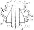
- Figure 1 is a sectional view of the system for fixing the recirculation line to the intake manifold of the engine according to the invention.
- a part of the engine exhaust gases are taken into the exhaust manifold by a metal pipe 2 which recirculates them in the air intake manifold 1 of the engine, downstream of the throttle valve for the engines thereof. equipped.
- a gas control valve is also provided in the recirculation line to adjust the flow rate of the recirculated exhaust gases according to the operating conditions of the engine.
- the end piece 8 of the metal recirculation pipe 2 is connected to a corresponding opening 7 of the intake manifold 1 by means of a flexible sleeve 6.
- This sleeve 6 is force fitted at one end to the manifold intake 1 while the other end receives the nozzle 8 of the recirculation line.
- the end piece 8 of the recirculation line comprises a substantially conical metal cup 4 surrounding the end of the recirculation line intended to be fitted into the other end of the sleeve 3.
- This cup 4 makes it possible to significantly lower the temperature of the nozzle and therefore allows it to be mounted in a flexible sleeve.
- the cup 4 is directly attached to the end of the pipe 2, for example by welding, the contact surface is as small as possible to reduce heat transfers.
- the cup 4 ends in a cylindrical part intended to come into contact with the sleeve 3, this cylindrical part having at its free end a folded edge 9 intended to come into abutment against the end of the sleeve 3
- the attachment of the sleeve to the cup is so operated by a simple clamp 5 which ensures gas tightness of this assembly.
- the flexible sleeve 6 is made of an elastic material, with a low coefficient of thermal conduction and resistant to temperatures of the order of 200 ° C. It is possible, for example, to use certain elastomers of the ethylene acrylic (VAMAC) or polychloroprene type, or also of the fluorocarbon rubber type. The use of such a thermally insulating sleeve therefore allows the use of a plastic intake manifold without risk of destruction of the latter due to the high temperature of the recirculation pipe.
- VAMAC ethylene acrylic
- polychloroprene type or also of the fluorocarbon rubber type.
- the sleeve 3 also comprises a central part 6 of substantially toroidal shape which creates an annular chamber surrounding the recirculation duct and opening into the opening 7.
- This annular chamber which can be swept by the fresh intake air passing through the manifold 1, contributes to cooling the nozzle 8 of the recirculation pipe by promoting heat exchanges.
- the use of an elastomer sleeve makes it possible to directly ensure gas tightness of the assembly without having recourse to specific seals.
- the flexibility of the sleeve 3 also makes it possible to dampen the vibrations of the recirculation pipe and therefore to reduce noise emissions. Furthermore, two parts are sufficient to ensure the fixing, which ensures the simplicity of assembly and the low cost of the fixing system.
Abstract
Description
La présente invention concerne un dispositif de recirculation des gaz d'échappement d'un moteur à combustion interne destiné plus particulièrement à équiper un véhicule automobile.The present invention relates to a device for recirculating the exhaust gases of an internal combustion engine intended more particularly for equipping a motor vehicle.
Les normes concernant la pollution et la consommation des moteurs à combustion interne équipant les véhicules automobiles, se sévérisent chaque jour davantage dans l'ensemble des pays industrialisés. L'industrie automobile est donc aujourd'hui occupée à trouver des solutions techniques pour répondre à ces obligations et ce, sans trop pénaliser ni les performances des moteurs ni leur prix de revient.The standards concerning pollution and consumption of internal combustion engines fitted to motor vehicles are becoming more stringent every day in all industrialized countries. The automotive industry is therefore now busy finding technical solutions to meet these obligations, without penalizing either the performance of the engines or their cost price.
Une technique connue de réduction des oxydes d'azote NOx, qui forment avec les hydrocarbures imbrûlés HC et le monoxyde de carbone CO les principaux polluants émis par les moteurs à combustion interne, consiste à opérer la recirculation d'une partie des gaz d'échappement dans les gaz frais d'admission. Cette technique consiste donc à réinjecter une quantité prédéterminée de gaz brûlés suivant les conditions de fonctionnement du moteur, dans le collecteur d'admission. Cet apport de gaz brûlés dans les gaz frais a pour effet de réduire la proportion de ces derniers au sein du mélange carburé introduit dans la chambre de combustion et donc d'abaisser la température de combustion, ce qui engendre une diminution de la production des NOx ou oxydes d'azote.A known technique for reducing nitrogen oxides NOx, which together with unburnt hydrocarbons HC and carbon monoxide CO are the main pollutants emitted by internal combustion engines, consists in recirculating part of the exhaust gases. in the gas admission fee. This technique therefore consists in reinjecting a predetermined quantity of burnt gases according to the operating conditions of the engine, into the manifold. of admission. This contribution of burnt gases in the fresh gases has the effect of reducing the proportion of the latter within the fuel mixture introduced into the combustion chamber and therefore of lowering the combustion temperature, which generates a reduction in the production of NOx or nitrogen oxides.
Le procédé généralement adopté est la "recirculation externe" des gaz d'échappement à l'aide d'une vanne EGR (Recyclage des Gaz d'Echappement) fermant ou ouvrant une conduite reliant le collecteur d'échappement et le collecteur d'admission. La vanne EGR est pilotée de façon à doser la quantité des gaz d'échappement admis à recirculer suivant les conditions de fonctionnement du moteur.The generally adopted process is the "external recirculation" of the exhaust gases using an EGR valve (Exhaust Gas Recycling) closing or opening a pipe connecting the exhaust manifold and the intake manifold. The EGR valve is controlled so as to dose the quantity of exhaust gases allowed to recirculate according to the operating conditions of the engine.
La conduite de recirculation a donc sa partie d'embout directement raccordée au collecteur d'admission. Pour ce faire, la partie d'embout comporte solidaire de celle-ci, par exemple par soudage, une bride de fixation de la conduite de recirculation au collecteur d'admission. La bride de fixation est immobilisée sur le collecteur d'admission avec interposition d'un joint d'étanchéité, au moyen de vis de fixation venant se loger dans des alésages taraudés correspondants usinés sur le collecteur d'admission.The recirculation line therefore has its end part directly connected to the intake manifold. To do this, the end part comprises integral with the latter, for example by welding, a flange for fixing the recirculation pipe to the intake manifold. The fixing flange is immobilized on the intake manifold with the interposition of a seal, by means of fixing screws which are received in corresponding threaded bores machined on the intake manifold.
Or les dispersions dues aux tolérances de fabrication font qu'au montage la conduite de recirculation se trouve parfois légèrement décalée dans l'espace, la bride de fixation n'étant plus alors en correspondance avec les puits de vis portés par le collecteur d'admission. Il s'avère donc nécessaire de réusiner après coup ces puits de vis, ce qui occasionne une augmentation du temps et du coût du montage.However, the dispersions due to manufacturing tolerances mean that during assembly the recirculation pipe is sometimes slightly offset in space, the fixing flange no longer being in correspondence with the screw wells. carried by the intake manifold. It is therefore necessary to remanufacture these screw wells after the fact, which increases the time and cost of assembly.
De plus, compte tenu des températures (supérieures à 200°C) auxquelles peut être portée la bride de fixation, il n'est pas possible d'utiliser un tel montage lorsque le collecteur est en matériau plastique ne résistant pas à de si hautes températures.In addition, given the temperatures (above 200 ° C) to which the mounting flange can be worn, it is not possible to use such an assembly when the collector is made of plastic material which does not withstand such high temperatures. .
La présente invention a donc pour objet de proposer un dispositif de recirculation des gaz d'échappement de moteur à combustion interne remédiant aux inconvénients de l'art antérieur précités et qui est à la fois simple et économique à réaliser.The object of the present invention is therefore to propose a device for recirculating the exhaust gases of an internal combustion engine overcoming the drawbacks of the aforementioned prior art and which is both simple and economical to produce.
Le dispositif de recirculation des gaz d'échappement d'un moteur à combustion interne, selon l'invention comprend une conduite de recirculation des gaz d'échappement du collecteur d'échappement au collecteur d'admission.The exhaust gas recirculation device of an internal combustion engine, according to the invention comprises an exhaust gas recirculation line from the exhaust manifold to the intake manifold.
Selon l'invention le dispositif de recirculation des gaz d'échappement est caractérisé en ce que la partie d'embout de la conduite de recirculation est raccordée au collecteur d'admission par l'intermédiaire de moyens de liaison permettant un déplacement relatif de la conduite de recirculation par rapport au collecteur d'admission, ces moyens de liaison assurant de plus l'isolation thermique du collecteur d'admission vis-à-vis de ladite conduite de recirculation et l'étanchéité aux gaz du raccordement.According to the invention, the exhaust gas recirculation device is characterized in that the end part of the recirculation pipe is connected to the intake manifold by means of connection means allowing relative movement of the pipe. recirculation with respect to the intake manifold, these connecting means also providing thermal insulation of the intake manifold with respect to said recirculation pipe and the gas tightness of the connection.
Selon une autre caractéristique du dispositif de recirculation des gaz d'échappement conformément à l'invention, ces moyens de liaison sont formés par un manchon flexible permettant des déplacements de la conduite de recirculation par rapport au collecteur d'admission dans les trois directions de l'espace.According to another characteristic of the exhaust gas recirculation device according to the invention, these connecting means are formed by a flexible sleeve allowing displacements of the recirculation pipe relative to the intake manifold in the three directions of the 'space.
Selon une autre caractéristique du dispositif de recirculation des gaz d'échappement conformément à l'invention, la partie d'embout de la conduite de recirculation comprend une coupelle venant entourée circonférentiellement la conduite de recirculation, cette coupelle étant directement fixée à l'extrémité de ladite conduite débouchant dans le collecteur d'admission.According to another characteristic of the exhaust gas recirculation device according to the invention, the end part of the recirculation pipe comprises a cup coming circumferentially surrounded by the recirculation pipe, this cup being directly fixed to the end of said pipe opening into the intake manifold.
Selon une autre caractéristique du dispositif de recirculation des gaz d'échappement conformément à l'invention, le bord rabattu de l'extrémité libre de la coupelle repose sur toute sa circonférence en appui contre une des extrémités du manchon.According to another characteristic of the exhaust gas recirculation device according to the invention, the folded edge of the free end of the cup rests over its entire circumference in abutment against one of the ends of the sleeve.
Selon une autre caractéristique du dispositif de recirculation des gaz d'échappement conformément à l'invention, le manchon est fixé directement sur la coupelle au moyen d'un collier de serrage.According to another characteristic of the exhaust gas recirculation device according to the invention, the sleeve is fixed directly to the cup by means of a clamp.
Selon une autre caractéristique du dispositif de recirculation des gaz d'échappement conformément à l'invention, le manchon est réalisé en un matériau élastique à fort coefficient d'isolation thermique.According to another characteristic of the exhaust gas recirculation device according to the invention, the sleeve is made of an elastic material with a high coefficient of thermal insulation.
Selon une autre caractéristique du dispositif de recirculation des gaz d'échappement conformément à l'invention, le manchon est fait en un matériau élastomère résistant à la température, du type caoutchouc fluorocarboné.According to another characteristic of the exhaust gas recirculation device according to the invention, the sleeve is made of an elastomeric material resistant to temperature, of the fluorocarbon rubber type.
Selon une autre caractéristique du dispositif de recirculation des gaz d'échappement conformément à l'invention, le manchon comporte une partie centrale de forme sensiblement torique.According to another characteristic of the exhaust gas recirculation device according to the invention, the sleeve comprises a central part of substantially toroidal shape.
On comprendra mieux les buts, aspects et avantages de la présente invention, d'après la description présentée ci-après d'un mode de réalisation de l'invention, donné à titre d'exemple non limitatif, en se référant au dessin annexé, dans lequel :
la figure 1 est une vue en coupe du système de fixation de la conduite de recirculation au collecteur d'admission du moteur selon l'invention.The aims, aspects and advantages of the present invention will be better understood from the description presented below of an embodiment of the invention, given by way of nonlimiting example, with reference to the appended drawing, in which :
Figure 1 is a sectional view of the system for fixing the recirculation line to the intake manifold of the engine according to the invention.
Seuls les éléments nécessaires à la compréhension de l'invention ont été représentés.Only the elements necessary for understanding the invention have been shown.
Une partie des gaz d'échappement du moteur sont prélevés dans le collecteur d'échappement par une conduite métallique 2 qui les recircule dans le collecteur d'admission d'air 1 du moteur, en aval du papillon des gaz pour les moteurs qui en sont équipés. Une vanne de régulation des gaz, non figurée, est par ailleurs prévue dans la conduite de recirculation pour ajuster le débit des gaz d'échappement recirculés suivant les conditions de fonctionnement du moteur.A part of the engine exhaust gases are taken into the exhaust manifold by a
La partie d'embout 8 de la conduite métallique de recirculation 2 est connectée à une ouverture 7 correspondante du collecteur d'admission 1 par l'intermédiaire d'un manchon flexible 6. Ce manchon 6 est emmanché à force par une extrémité sur le collecteur d'admission 1 tandis que l'autre extrémité reçoit l'embout 8 de la conduite de recirculation.The
L'embout 8 de la conduite de recirculation comprend une coupelle sensiblement conique métallique 4 entourant l'extrémité de la conduite de recirculation destinée à être emmanchée dans l'autre extrémité du manchon 3.The
Cette coupelle 4 permet d'abaisser sensiblement la température de l'embout et permet donc son montage dans un manchon flexible. La coupelle 4 est directement solidaire de l'extrémité de la conduite 2, par exemple par soudage, la surface de contact est la plus faible possible pour réduire les transferts thermiques.This
La coupelle 4 se termine par une partie cylindrique destinée à venir au contact du manchon 3, cette partie cylindrique présentant à son extrémité libre un bord rabattu 9 destiné à venir en butée contre l'extrémité du manchon 3 La solidarisation du manchon à la coupelle est alors opérée par un simple collier de serrage 5 qui assure l'étanchéité aux gaz de ce montage.The
Le manchon flexible 6 est réalisé en un matériau élastique, à faible coefficient de conduction thermique et résistant à des températures de l'ordre de 200°C. On peut par exemple utiliser certains élastomères du type éthylène acrylique (VAMAC) ou polychloroprène, ou encore du type caoutchouc fluorocarboné. L'utilisation d'un tel manchon isolant thermiquement permet donc l'utilisation de collecteur d'admission en matière plastique sans risque de destruction de ce dernier du fait de la température élevée de la conduite de recirculation.The
Le manchon 3 comporte par ailleurs une partie centrale 6 de forme sensiblement torique qui crée une chambre annulaire entourant le conduit de recirculation et débouchant dans l'ouverture 7. Cette chambre annulaire, pouvant être balayée par l'air frais d'admission traversant le collecteur 1, contribue à refroidir l'embout 8 de la conduite de recirculation en favorisant les échanges thermiques.The
Ainsi grâce au système de fixation de la conduite de recirculation des gaz sur le collecteur d'admission, il est possible d'opérer la fixation de la conduite de recirculation 2 sur le collecteur d'admission 1 alors même que la conduite 2 ne se trouve pas positionnée exactement au centre de l'ouverture 7, du fait notamment de dispersions de fabrication. Il suffit lors du montage de déplacer l'extrémité du manchon au contact de la coupelle 4 en utilisant la flexibilité du manchon.Thus, thanks to the system for fixing the gas recirculation pipe to the intake manifold, it is possible to fix the
L'utilisation d'un manchon en élastomère permet d'assurer directement l'étanchéité aux gaz du montage sans avoir recours à des joints d'étanchéité spécifique. La souplesse du manchon 3 permet de plus d'amortir les vibrations de la conduite de recirculation et donc de réduire les émissions sonores. Par ailleurs deux pièces suffisent pour assurer la fixation, ce qui assure la simplicité de montage et le faible coût du système de fixation.The use of an elastomer sleeve makes it possible to directly ensure gas tightness of the assembly without having recourse to specific seals. The flexibility of the
Bien entendu, l'invention n'est nullement limitée au mode de réalisation décrit et illustré qui n'a été donné qu'à titre d'exemple.Of course, the invention is in no way limited to the embodiment described and illustrated, which has been given only by way of example.
Au contraire, l'invention comprend tous les équivalents techniques des moyens décrits ainsi que leurs combinaisons si celles-ci sont effectuées suivant son esprit.On the contrary, the invention includes all the technical equivalents of the means described and their combinations if these are carried out according to the spirit.
Claims (8)
Applications Claiming Priority (2)
| Application Number | Priority Date | Filing Date | Title |
|---|---|---|---|
| FR9312005A FR2710952B1 (en) | 1993-10-08 | 1993-10-08 | Exhaust gas recirculation device for an internal combustion engine. |
| FR9312005 | 1993-10-08 |
Publications (1)
| Publication Number | Publication Date |
|---|---|
| EP0647779A1 true EP0647779A1 (en) | 1995-04-12 |
Family
ID=9451666
Family Applications (1)
| Application Number | Title | Priority Date | Filing Date |
|---|---|---|---|
| EP94402241A Withdrawn EP0647779A1 (en) | 1993-10-08 | 1994-10-06 | Exhaust gas recirculation device for an internal combustion engine |
Country Status (2)
| Country | Link |
|---|---|
| EP (1) | EP0647779A1 (en) |
| FR (1) | FR2710952B1 (en) |
Cited By (8)
| Publication number | Priority date | Publication date | Assignee | Title |
|---|---|---|---|---|
| DE19627035A1 (en) * | 1996-07-05 | 1998-01-08 | Elringklinger Gmbh | Exhaust gas recirculation device |
| FR2768483A1 (en) * | 1997-09-15 | 1999-03-19 | Bosch Gmbh Robert | MIXER VALVE, IN PARTICULAR EXHAUST GAS REINJECTION VALVE OF AN INTERNAL COMBUSTION ENGINE |
| DE19807463A1 (en) * | 1998-02-24 | 1999-08-26 | Mannesmann Vdo Ag | Intake device for IC engine |
| FR2833312A1 (en) * | 2001-12-11 | 2003-06-13 | Qualetude | Exhaust gas recirculation duct for motor vehicle internal combustion engine has tube with end couplings and corrugated section at one end to absorb vibration |
| FR2844008A1 (en) * | 2002-08-29 | 2004-03-05 | Siemens Vdo Automotive Inc | DOUBLE SEALED EGR TUBE ASSEMBLY |
| FR2910068A1 (en) * | 2006-12-13 | 2008-06-20 | Renault Sas | Exhaust gas recirculation device for internal combustion engine of motor vehicle, has exhaust gas recirculation conduits extending from nozzle until air intake system, where part of one of conduits is made of flexible polymer material |
| WO2013026894A3 (en) * | 2011-08-25 | 2013-05-30 | Mahle International Gmbh | Arrangement for the fluidic and mechanical connection of two components |
| CN107327360A (en) * | 2016-09-26 | 2017-11-07 | 吴潮生 | Automobile-used air inlet pipe |
Citations (3)
| Publication number | Priority date | Publication date | Assignee | Title |
|---|---|---|---|---|
| FR2588916A1 (en) * | 1985-10-18 | 1987-04-24 | Renault | Flexible coupling device for exhaust pipes at high temperatures |
| EP0486338A1 (en) * | 1990-11-14 | 1992-05-20 | Automobiles Peugeot | Intake manifold for internal combustion engine having an exhaust gas recirculation device |
| DE9205401U1 (en) * | 1992-04-21 | 1992-06-25 | Fichtel & Sachs Ag, 8720 Schweinfurt, De |
-
1993
- 1993-10-08 FR FR9312005A patent/FR2710952B1/en not_active Expired - Fee Related
-
1994
- 1994-10-06 EP EP94402241A patent/EP0647779A1/en not_active Withdrawn
Patent Citations (3)
| Publication number | Priority date | Publication date | Assignee | Title |
|---|---|---|---|---|
| FR2588916A1 (en) * | 1985-10-18 | 1987-04-24 | Renault | Flexible coupling device for exhaust pipes at high temperatures |
| EP0486338A1 (en) * | 1990-11-14 | 1992-05-20 | Automobiles Peugeot | Intake manifold for internal combustion engine having an exhaust gas recirculation device |
| DE9205401U1 (en) * | 1992-04-21 | 1992-06-25 | Fichtel & Sachs Ag, 8720 Schweinfurt, De |
Cited By (17)
| Publication number | Priority date | Publication date | Assignee | Title |
|---|---|---|---|---|
| DE19627035A1 (en) * | 1996-07-05 | 1998-01-08 | Elringklinger Gmbh | Exhaust gas recirculation device |
| DE19627035C2 (en) * | 1996-07-05 | 1998-07-16 | Elringklinger Gmbh | Exhaust gas recirculation device |
| FR2768483A1 (en) * | 1997-09-15 | 1999-03-19 | Bosch Gmbh Robert | MIXER VALVE, IN PARTICULAR EXHAUST GAS REINJECTION VALVE OF AN INTERNAL COMBUSTION ENGINE |
| DE19807463A1 (en) * | 1998-02-24 | 1999-08-26 | Mannesmann Vdo Ag | Intake device for IC engine |
| US6443134B1 (en) | 1998-02-24 | 2002-09-03 | Mannesmann Vdo Ag | Intake device for an internal combustion engine |
| FR2833312A1 (en) * | 2001-12-11 | 2003-06-13 | Qualetude | Exhaust gas recirculation duct for motor vehicle internal combustion engine has tube with end couplings and corrugated section at one end to absorb vibration |
| EP1319826A1 (en) | 2001-12-11 | 2003-06-18 | Qualetude | Exhaust gas recirculation device for internal combustion engines |
| FR2844008A1 (en) * | 2002-08-29 | 2004-03-05 | Siemens Vdo Automotive Inc | DOUBLE SEALED EGR TUBE ASSEMBLY |
| FR2910068A1 (en) * | 2006-12-13 | 2008-06-20 | Renault Sas | Exhaust gas recirculation device for internal combustion engine of motor vehicle, has exhaust gas recirculation conduits extending from nozzle until air intake system, where part of one of conduits is made of flexible polymer material |
| EP1936176A1 (en) * | 2006-12-13 | 2008-06-25 | Renault S.A.S. | Device for recirculating exhaust gas from an internal combustion engine of an automobile |
| WO2013026894A3 (en) * | 2011-08-25 | 2013-05-30 | Mahle International Gmbh | Arrangement for the fluidic and mechanical connection of two components |
| CN103797290A (en) * | 2011-08-25 | 2014-05-14 | 福特维克公司 | Arrangement for the fluidic and mechanical connection of two components |
| CN103797290B (en) * | 2011-08-25 | 2016-03-09 | 福特维克公司 | For fluid and the device be mechanically connected of two parts |
| RU2597726C2 (en) * | 2011-08-25 | 2016-09-20 | Форд-Верке ГмбХ | Device for mechanical and fluid connection of two structural elements |
| US9453603B2 (en) | 2011-08-25 | 2016-09-27 | Mahle International Gmbh | Arrangement for the fluidic and mechanical connection of two components |
| CN107327360A (en) * | 2016-09-26 | 2017-11-07 | 吴潮生 | Automobile-used air inlet pipe |
| CN107327360B (en) * | 2016-09-26 | 2023-04-07 | 吴潮生 | Air inlet pipe for vehicle |
Also Published As
| Publication number | Publication date |
|---|---|
| FR2710952B1 (en) | 1995-11-17 |
| FR2710952A1 (en) | 1995-04-14 |
Similar Documents
| Publication | Publication Date | Title |
|---|---|---|
| EP1705340A2 (en) | Connector between a cooling air plenum and a stator vane in a turbomachine | |
| FR2930278A1 (en) | Exhaust gas recirculation module for vehicle's internal combustion engine, has heat exchanger connected to recirculated exhaust gas conduit, and filter assembly placed in rectilinear portion of conduit and removably fixed on conduit | |
| WO2004097192A2 (en) | Exhaust for internal combustion engine | |
| FR2943384A1 (en) | EXHAUST CIRCUIT FOR MOTOR VEHICLE | |
| EP0647779A1 (en) | Exhaust gas recirculation device for an internal combustion engine | |
| FR2586270A1 (en) | CONNECTING PIPING BETWEEN A COMPRESSOR OF A TURBOCHARGER ON THE EXHAUST GAS CONNECTED BY FLANGE TO AN ELBOW CONNECTION OF THE EXHAUST GASES OF AN INTERNAL COMBUSTION ENGINE AND AN INTAKE TUBING | |
| EP1422412A2 (en) | Exhaust gas recirculation device of internal combustion engine | |
| FR2908831A1 (en) | ARRANGEMENT FOR THE ASSEMBLY OF AN EXHAUST GAS DERIVATION DRIVE HAVING AN UPPER END FRONT PORTION BY A DEPOLLUTION DEVICE | |
| EP0486338B1 (en) | Intake manifold for internal combustion engine having an exhaust gas recirculation device | |
| EP2960482A2 (en) | Exhaust gas recirculation system | |
| EP0956442B1 (en) | Device for recycling the exhaust gases of an internal combustion engine | |
| FR2740511A1 (en) | I.C. engine exhaust gas recirculator | |
| FR2926845A1 (en) | Flexible exhaust pipe element for motor vehicle, has flexible inner and outer tubes maintained in relative position by end flanges, where inner tube defines central passage, and annular channel formed between inner and outer tubes | |
| FR2719870A1 (en) | IC engine exhaust gas recirculator | |
| EP1422411B1 (en) | Exhaust gas recirculation device of internal combustion engine | |
| FR2721349A1 (en) | Exhaust gas recirculator for IC engine | |
| FR3050232A3 (en) | FIXING RING PROTECTION SCREEN | |
| FR2933045A1 (en) | Air intake pipe fixation system for fan fairing in motor vehicle, has groove extended in bottom of housing of fairing, where upper face of fairing has bonnet movable between open position and closed position in which bonnet closes opening | |
| FR2844008A1 (en) | DOUBLE SEALED EGR TUBE ASSEMBLY | |
| FR2910068A1 (en) | Exhaust gas recirculation device for internal combustion engine of motor vehicle, has exhaust gas recirculation conduits extending from nozzle until air intake system, where part of one of conduits is made of flexible polymer material | |
| FR2663371A1 (en) | Device of a circuit for recycling the crankcase gases of an engine | |
| US11525379B2 (en) | Exhaust-gas tract for a motor vehicle | |
| JP7255960B2 (en) | Intake system for internal combustion engine | |
| FR2738289A1 (en) | IC engine exhaust duct | |
| FR2722243A1 (en) | Exhaust manifold for IC engine |
Legal Events
| Date | Code | Title | Description |
|---|---|---|---|
| PUAI | Public reference made under article 153(3) epc to a published international application that has entered the european phase |
Free format text: ORIGINAL CODE: 0009012 |
|
| AK | Designated contracting states |
Kind code of ref document: A1 Designated state(s): DE ES GB IT |
|
| 17P | Request for examination filed |
Effective date: 19950920 |
|
| 17Q | First examination report despatched |
Effective date: 19970204 |
|
| GRAG | Despatch of communication of intention to grant |
Free format text: ORIGINAL CODE: EPIDOS AGRA |
|
| STAA | Information on the status of an ep patent application or granted ep patent |
Free format text: STATUS: THE APPLICATION HAS BEEN WITHDRAWN |
|
| 18W | Application withdrawn |
Withdrawal date: 19990609 |