EP0647760B1 - Fixing means for the anchorage in slabs, particularly made of glass - Google Patents
Fixing means for the anchorage in slabs, particularly made of glass Download PDFInfo
- Publication number
- EP0647760B1 EP0647760B1 EP94110625A EP94110625A EP0647760B1 EP 0647760 B1 EP0647760 B1 EP 0647760B1 EP 94110625 A EP94110625 A EP 94110625A EP 94110625 A EP94110625 A EP 94110625A EP 0647760 B1 EP0647760 B1 EP 0647760B1
- Authority
- EP
- European Patent Office
- Prior art keywords
- expansion
- expansible
- undercut
- wall
- glass
- Prior art date
- Legal status (The legal status is an assumption and is not a legal conclusion. Google has not performed a legal analysis and makes no representation as to the accuracy of the status listed.)
- Expired - Lifetime
Links
- 239000011521 glass Substances 0.000 title claims abstract description 22
- 239000000463 material Substances 0.000 claims abstract description 6
- 239000002184 metal Substances 0.000 claims abstract description 6
- 239000004033 plastic Substances 0.000 claims abstract description 6
- 229920003023 plastic Polymers 0.000 claims abstract description 6
- 230000006835 compression Effects 0.000 claims description 6
- 238000007906 compression Methods 0.000 claims description 6
- 125000006850 spacer group Chemical group 0.000 claims description 6
- 238000010276 construction Methods 0.000 claims 1
- 238000004873 anchoring Methods 0.000 description 9
- 239000004579 marble Substances 0.000 description 2
- 239000004575 stone Substances 0.000 description 2
- 229910000831 Steel Inorganic materials 0.000 description 1
- 239000011324 bead Substances 0.000 description 1
- 230000015572 biosynthetic process Effects 0.000 description 1
- 230000002349 favourable effect Effects 0.000 description 1
- 238000002347 injection Methods 0.000 description 1
- 239000007924 injection Substances 0.000 description 1
- 238000009434 installation Methods 0.000 description 1
- 238000007789 sealing Methods 0.000 description 1
- 239000010959 steel Substances 0.000 description 1
Images

Classifications
-
- E—FIXED CONSTRUCTIONS
- E04—BUILDING
- E04F—FINISHING WORK ON BUILDINGS, e.g. STAIRS, FLOORS
- E04F13/00—Coverings or linings, e.g. for walls or ceilings
- E04F13/07—Coverings or linings, e.g. for walls or ceilings composed of covering or lining elements; Sub-structures therefor; Fastening means therefor
- E04F13/08—Coverings or linings, e.g. for walls or ceilings composed of covering or lining elements; Sub-structures therefor; Fastening means therefor composed of a plurality of similar covering or lining elements
- E04F13/0801—Separate fastening elements
- E04F13/0832—Separate fastening elements without load-supporting elongated furring elements between wall and covering elements
- E04F13/0833—Separate fastening elements without load-supporting elongated furring elements between wall and covering elements not adjustable
- E04F13/0835—Separate fastening elements without load-supporting elongated furring elements between wall and covering elements not adjustable the fastening elements extending into the back side of the covering elements
-
- E—FIXED CONSTRUCTIONS
- E06—DOORS, WINDOWS, SHUTTERS, OR ROLLER BLINDS IN GENERAL; LADDERS
- E06B—FIXED OR MOVABLE CLOSURES FOR OPENINGS IN BUILDINGS, VEHICLES, FENCES OR LIKE ENCLOSURES IN GENERAL, e.g. DOORS, WINDOWS, BLINDS, GATES
- E06B3/00—Window sashes, door leaves, or like elements for closing wall or like openings; Layout of fixed or moving closures, e.g. windows in wall or like openings; Features of rigidly-mounted outer frames relating to the mounting of wing frames
- E06B3/54—Fixing of glass panes or like plates
- E06B3/5436—Fixing of glass panes or like plates involving holes or indentations in the pane
-
- F—MECHANICAL ENGINEERING; LIGHTING; HEATING; WEAPONS; BLASTING
- F16—ENGINEERING ELEMENTS AND UNITS; GENERAL MEASURES FOR PRODUCING AND MAINTAINING EFFECTIVE FUNCTIONING OF MACHINES OR INSTALLATIONS; THERMAL INSULATION IN GENERAL
- F16B—DEVICES FOR FASTENING OR SECURING CONSTRUCTIONAL ELEMENTS OR MACHINE PARTS TOGETHER, e.g. NAILS, BOLTS, CIRCLIPS, CLAMPS, CLIPS OR WEDGES; JOINTS OR JOINTING
- F16B13/00—Dowels or other devices fastened in walls or the like by inserting them in holes made therein for that purpose
- F16B13/04—Dowels or other devices fastened in walls or the like by inserting them in holes made therein for that purpose with parts gripping in the hole or behind the reverse side of the wall after inserting from the front
- F16B13/08—Dowels or other devices fastened in walls or the like by inserting them in holes made therein for that purpose with parts gripping in the hole or behind the reverse side of the wall after inserting from the front with separate or non-separate gripping parts moved into their final position in relation to the body of the device without further manual operation
- F16B13/0858—Dowels or other devices fastened in walls or the like by inserting them in holes made therein for that purpose with parts gripping in the hole or behind the reverse side of the wall after inserting from the front with separate or non-separate gripping parts moved into their final position in relation to the body of the device without further manual operation with an expansible sleeve or dowel body driven against a tapered or spherical expander plug
-
- F—MECHANICAL ENGINEERING; LIGHTING; HEATING; WEAPONS; BLASTING
- F16—ENGINEERING ELEMENTS AND UNITS; GENERAL MEASURES FOR PRODUCING AND MAINTAINING EFFECTIVE FUNCTIONING OF MACHINES OR INSTALLATIONS; THERMAL INSULATION IN GENERAL
- F16B—DEVICES FOR FASTENING OR SECURING CONSTRUCTIONAL ELEMENTS OR MACHINE PARTS TOGETHER, e.g. NAILS, BOLTS, CIRCLIPS, CLAMPS, CLIPS OR WEDGES; JOINTS OR JOINTING
- F16B13/00—Dowels or other devices fastened in walls or the like by inserting them in holes made therein for that purpose
- F16B2013/007—Dowels or other devices fastened in walls or the like by inserting them in holes made therein for that purpose to be fastened in undercut holes
Definitions
- the invention relates to a fastening element according to the preamble of claim 1 for anchoring in preferably made of glass or similar material Plates.
- a fastening element is known from DE 40 30 498 A1, which is pushed on of an expansion element on the expansion cone of an expansion bolt in an undercut Drill hole of a facade panel made of natural stone, marble or the like can be anchored.
- the expansion element is pushed onto the expansion cone via a spacer element designed as a plastic disc by screwing on a Nut on the threaded section of the expansion bolt.
- the expansion element designed as a slotted expansion sleeve can be anchored as an expansion bolt via a blind rivet.
- the setting head is anchored in the expansion sleeve in the undercut of the borehole the blind rivet with the rivet mandrel in the slotted part of the inner bore of the expansion sleeve drawn in and riveted.
- the metal expansion element is against the wall of the undercut borehole pressed.
- existing facade panel is a recording of the metallic expansion element outgoing spreading pressure possible without further ado because of the structure of the Stress relief occurs.
- the known ones are not suitable Fasteners for anchoring in very hard and inelastic panels such as for example glass. When using the known fasteners in such Plates have the risk that both during assembly and by additional the borehole breaks out on the loads acting on the fastening element.
- the invention has for its object to provide a fastener that in plates made of glass or similar material can be securely anchored.
- the pressing element In the case of an expansion element consisting of a wire ring, which is formed by several roof-shaped elements bent ring sections is formed, it is appropriate to the pressing element form sleeve-shaped and extend with a spacer, on which one on the Outside surface of the plate seated flange is arranged.
- the pressing element When screwing one Nut on the threaded portion of the expansion bolt is with the face of the Spacer pushed the expansion element onto the expansion cone and at the same time with the expansion element, the pressing element against the wall of the undercut of the borehole pressed.
- the flange on the outer surface of the plate becomes thereby braced against the outer surface of the glass plate, so that both direct contact the mother with the outer surface of the glass plate avoided as well as a seal of the borehole is reached.
- the inner wall of the Pressing element with a recess receiving the expansion element, and the pressing element a plurality of wall segments covering the expansion element exhibit.
- the expansion bolt of the fastener according to the invention can be used as a blind rivet and the expansion element can be designed as a slotted expansion sleeve.
- the fastener is useful as a pressing element To use rubber ring, which is arranged on the slotted part of the expansion sleeve.
- the fastener is in an undercut hole Push the glass plate in until the face of the expansion sleeve is on the bottom of the borehole sits on.
- the blind rivet with its setting head is passed through a hole of the object to be fastened to the back of the plate and through the Insert the inner bore of the expansion sleeve until the rivet head on the outer surface of the object to be fastened.
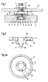
- the fastener 1 shown in Figure 1 consists of an expansion bolt 2, the one at its front end an expansion cone 3 and at its rear end Has thread 4.
- an expansion element 5 is arranged, the for anchoring the fastening element 1 in the glass pane 6 on the expansion cone 3 is pressed.
- the pressing takes place of the expansion element 5 by unscrewing the nut 7 on the threaded portion 4 of the Spreader bolt 2.
- the spreading element 5 consisting of a metal wire does not come directly in contact with the wall of the glass plate 6. Since the pressing element 8 from a soft Plastic, there is a gentle and avoiding voltage spikes Anchoring the fastening element 1. With the expansion element spreading 5 at the same time the flange 14 of the pressing element 8 against the surface the glass plate 6 clamped.
- the glass plate 6 is attached to a support 17 of a substructure via a further nut 18, between which and the mother 7 of the carrier 17 is clamped.
- FIGs 2 and 2a show the embodiment of the made of a soft plastic Pressing element 8 as an injection molded part.
- the sleeve-shaped pressing element 8 is with the Extended spacer 10 on which the flange 14 is arranged. Opposite the edge 14 are the wall segments 11 of the pressing element 8, that of the expansion element pressed against the wall of the undercut of the borehole in the glass pane become.
- the number of wall segments 11 corresponds to the number of ring sections of the expansion element 5.
- In the inner wall of the wall segments 11 are recesses 20 introduced that accommodate the expansion element 5.
- the embodiment of the fastener 21 according to Figures 3 and 4 has as Expanding bolt on a blind rivet 22.
- Figure 3 shows the state of the fastener 21 before anchoring in the undercut 12 of the borehole 13, wherein the expansion sleeve 23 is inserted into the borehole 13.
- the resulting through slots 25 Spreading segments 26 of the expansion sleeve 23 are for inserting the fastening element bent inwards so far that that on the outer surface of the expansion segments 26 arranged circumferential bead 27 a the borehole diameter in the glass plate 6 has a corresponding diameter.
- the fastening object 28 for example a hook, fastening bracket or Like.
- On the back of the glass plate 6 is through the inner bore 29 of the expansion sleeve 23 of the blind rivet 22 inserted until the rivet head 30 on the outer surface of the fastening object 28 abuts.
- On the expansion segments 26 is as a pressing element a rubber ring 31 put on.
Landscapes
- Engineering & Computer Science (AREA)
- Architecture (AREA)
- Civil Engineering (AREA)
- Structural Engineering (AREA)
- General Engineering & Computer Science (AREA)
- Mechanical Engineering (AREA)
- Load-Bearing And Curtain Walls (AREA)
- Dowels (AREA)
- Glass Compositions (AREA)
- Connection Of Plates (AREA)
- Joining Of Building Structures In Genera (AREA)
- Securing Of Glass Panes Or The Like (AREA)
- Joining Of Glass To Other Materials (AREA)
Abstract
Description
Die Erfindung betrifft ein Befestigungselement gemäß der Gattung des Anspruches 1
für die Verankerung in vorzugsweise aus Glas oder ähnlichem Material bestehenden
Platten.The invention relates to a fastening element according to the preamble of
Aus der DE 40 30 498 A1 ist ein Befestigungselement bekannt, das durch Aufschieben eines Spreizelementes auf den Spreizkonus eines Spreizbolzens in einem hinterschnittenen Bohrloch einer aus Naturstein, Marmor oder dgl. bestehenden Fassadenplatte verankerbar ist. Das Aufschieben des Spreizelementes auf den Spreizkonus erfolgt über ein als Kunststoffscheibe ausgebildetes Distanzelement durch Aufschrauben einer Mutter auf den Gewindeabschnitt des Spreizbolzens.A fastening element is known from DE 40 30 498 A1, which is pushed on of an expansion element on the expansion cone of an expansion bolt in an undercut Drill hole of a facade panel made of natural stone, marble or the like can be anchored. The expansion element is pushed onto the expansion cone via a spacer element designed as a plastic disc by screwing on a Nut on the threaded section of the expansion bolt.
Zur Durchführung einer Befestigung in einem hinterschnittenen Bohrloch einer Fassadenplatte ist aus der DE 42 02 774 A1 ein weiteres aus Metall bestehendes Befestigungselement bekannt, bei dem das als geschlitzte Spreizhülse ausgebildete Spreizelement über einen Blindniet als Spreizbolzen verankerbar ist. Zum Aufspreizen und Verankern der Spreizhülse in der Hinterschneidung des Bohrloches wird der Setzkopf des Blindniets mit dem Nietdorn in den geschlitzten Teil der Innenbohrung der Spreizhülse eingezogen und vernietet.For mounting in an undercut hole in a facade panel is another fastening element made of metal from DE 42 02 774 A1 known in which the expansion element designed as a slotted expansion sleeve can be anchored as an expansion bolt via a blind rivet. For spreading and The setting head is anchored in the expansion sleeve in the undercut of the borehole the blind rivet with the rivet mandrel in the slotted part of the inner bore of the expansion sleeve drawn in and riveted.
In beiden Fällen wird das aus Metall bestehende Spreizelement gegen die Wandung des hinterschnittenen Bohrloches gepreßt. Bei einer aus Naturstein, Marmor oder dgl. bestehenden Fassadenplatte ist eine Aufnahme des von dem metallischen Spreizelement ausgehenden Spreizdruckes ohne weiteres möglich, da über die Struktur des Materials ein Spannungsabbau erfolgt. Nicht geeignet sind jedoch die bekannten Befestigungselemente für Verankerungen in sehr harten und unelastischen Platten wie beispielsweise Glas. Bei einem Einsatz der bekannten Befestigungselemente in solchen Platten besteht die Gefahr, daß sowohl bei der Montage als auch durch zusätzlich am Befestigungselement angreifenden Belastungen das Bohrloch ausbricht. In both cases, the metal expansion element is against the wall of the undercut borehole pressed. In the case of natural stone, marble or the like. existing facade panel is a recording of the metallic expansion element outgoing spreading pressure possible without further ado because of the structure of the Stress relief occurs. However, the known ones are not suitable Fasteners for anchoring in very hard and inelastic panels such as for example glass. When using the known fasteners in such Plates have the risk that both during assembly and by additional the borehole breaks out on the loads acting on the fastening element.
Der Erfindung liegt die Aufgabe zugrunde, ein Befestigungselement zu schaffen, das in aus Glas oder ähnlichem Material bestehenden Platten sicher verankerbar ist.The invention has for its object to provide a fastener that in plates made of glass or similar material can be securely anchored.
Die Lösung dieser Aufgabe wird mit den im Anspruch 1 angegebenen Merkmalen erreicht.
Mit dem zwischen dem Spreizelement und der Wandung des hinterschnittenen
Bohrloches angeordneten Preßelement wird ein direkter Kontakt des aus Stahl bestehenden
Spreizelementes mit der Glasoberfläche vermieden. Das aus einem weichen
Kunststoff bestehende Preßelement ist elastisch und/oder plastisch verformbar, so daß
aus einer starren, unter Umständen zu einem Bruch des Glases führenden Punktbelastung
eine weiche und Unebenheiten ausgleichende Flächenbelastung wird. Durch
die sich daraus ergebende gleichmäßigere Druckverteilung auf eine größere Fläche
lassen sich mit dem erfindungsgemäßen Befestigungselement auch in sehr spröden
Platten wie Glas hohe Bruchlasten erzielen. Das Befestigungselement eignet sich somit
für die verdeckte und sichere Montage von aus Glas oder ähnlichem Material bestehenden
Fassadenplatten. Da der Formschluß des Befestigungselementes im hinterschnittenen
Bohrloch weiterhin auf Metallteilen beruht, wird auch im Brandfalle eine
hohe Sicherheit gegen Herunterfallen der Platte erreicht.This object is achieved with the features specified in
Bei einem aus einem Drahtring bestehenden Spreizelement, das durch mehrere dachförmig abgebogene Ringabschnitte gebildet ist, ist es zweckmäßig, das Preßelement hülsenförmig auszubilden und mit einem Distanzteil zu verlängern, an dem ein auf der Außenfläche der Platte aufsitzender Flansch angeordnet ist. Beim Aufschrauben einer Mutter auf den Gewindeabschnitt des Spreizbolzens wird mit der Stirnfläche des Distanzteiles das Spreizelement auf den Spreizkonus aufgeschoben und gleichzeitig mit dem Spreizelement das Preßelement gegen die Wandung der Hinterschneidung des Bohrloches gepreßt. Der an der Außenfläche der Platte aufsitzende Flansch wird dabei gegen die Außenfläche der Glasplatte verspannt, so daß sowohl eine direkte Berührung der Mutter mit der Außenfläche der Glasplatte vermieden als auch eine Abdichtung des Bohrloches erreicht wird.In the case of an expansion element consisting of a wire ring, which is formed by several roof-shaped elements bent ring sections is formed, it is appropriate to the pressing element form sleeve-shaped and extend with a spacer, on which one on the Outside surface of the plate seated flange is arranged. When screwing one Nut on the threaded portion of the expansion bolt is with the face of the Spacer pushed the expansion element onto the expansion cone and at the same time with the expansion element, the pressing element against the wall of the undercut of the borehole pressed. The flange on the outer surface of the plate becomes thereby braced against the outer surface of the glass plate, so that both direct contact the mother with the outer surface of the glass plate avoided as well as a seal of the borehole is reached.
Um das Überstülpen des hülsenförmigen Preßelementes über das Spreizelement bei günstigen Durchmesserverhältnissen zu ermöglichen, kann die Innenwandung des Preßelementes mit einer das Spreizelement aufnehmenden Aussparung versehen sein, und das Preßelement mehrere, das Spreizelement überdeckende Wandsegmente aufweisen.To put the sleeve-shaped pressing element over the expansion element To enable favorable diameter ratios, the inner wall of the Pressing element with a recess receiving the expansion element, and the pressing element a plurality of wall segments covering the expansion element exhibit.
Der Spreizbolzen des erfindungsgemäßen Befestigungselementes kann als Blindniet und das Spreizelement als geschlitzte Spreizhülse ausgebildet sein. Bei einer derartigen Gestaltung des Befestigungselementes ist es zweckmäßig, als Preßelement einen Gummiring zu verwenden, der auf dem geschlitzten Teil der Spreizhülse angeordnet ist. Zur Verankerung wird das Befestigungselement in ein hinterschnittenes Bohrloch der Glasplatte soweit eingeschoben, bis die Stirnseite der Spreizhülse auf dem Bohrlochgrund aufsitzt. Danach wird der Blindniet mit seinem Setzkopf voraus durch eine Bohrung des auf die Rückseite der Platte zu befestigenden Gegenstandes und durch die Innenbohrung der Spreizhülse soweit eingeschoben, bis der Nietkopf an der Außenfläche des zu befestigenden Gegenstandes anliegt. Mit einer Nietzange wird über den Nietdorn der Setzkopf des Blindniets in den geschlitzten Teil der Innenbohrung der Spreizhülse eingezogen und vernietet. Durch die Stauchung und Ausbildung des Setzkopfes wird die Spreizhülse und der auf der Spreizhülse angeordnete Gummiring aufgeweitet und gegen die Bohrlochwandung der Hinterschneidung gepreßt. Der sich verformende Gummiring schafft somit eine weiche Zwischenlage zwischen der Wandung der Hinterschneidung und der Außenwandung der Spreizhülse.The expansion bolt of the fastener according to the invention can be used as a blind rivet and the expansion element can be designed as a slotted expansion sleeve. With such a Design of the fastener, it is useful as a pressing element To use rubber ring, which is arranged on the slotted part of the expansion sleeve. For anchoring, the fastener is in an undercut hole Push the glass plate in until the face of the expansion sleeve is on the bottom of the borehole sits on. Then the blind rivet with its setting head is passed through a hole of the object to be fastened to the back of the plate and through the Insert the inner bore of the expansion sleeve until the rivet head on the outer surface of the object to be fastened. With rivet pliers, the Rivet mandrel the setting head of the blind rivet in the slotted part of the inner bore of the Expansion sleeve retracted and riveted. Due to the compression and formation of the setting head the expansion sleeve and the rubber ring arranged on the expansion sleeve are expanded and pressed against the borehole wall of the undercut. The deforming Rubber ring thus creates a soft intermediate layer between the wall the undercut and the outer wall of the expansion sleeve.
Die Erfindung wird nachfolgend anhand in der Zeichnung dargestellter Ausführungsbeispiele näher erläutert.The invention is described below with reference to exemplary embodiments shown in the drawing explained in more detail.
Es zeigen:
Figur 1- das in einer Glasplatte verankerte Befestigungselement,
Figur 2- das Preßelement in einer bei dem Befestigungselement nach
Figur 1 verwendeten Ausführungsform, - Figur 2a
- eine Draufsicht auf die Unterseite des Preßelementes nach
Figur 2, Figur 3- eine Ausführungsform des Befestigungselementes mit einem Blindniet als Spreizbolzen vor der Verankerung und
- Figur 4
- das Befestigungselement nach
Figur 3 nach der Verankerung.
- Figure 1
- the fastener anchored in a glass plate,
- Figure 2
- the pressing element in an embodiment used in the fastener of Figure 1,
- Figure 2a
- 3 shows a plan view of the underside of the pressing element according to FIG. 2,
- Figure 3
- an embodiment of the fastener with a blind rivet as an expansion bolt before anchoring and
- Figure 4
- the fastener of Figure 3 after anchoring.
Das in Figur 1 dargestellte Befestigungselement 1 besteht aus einem Spreizbolzen 2,
der an seinem vorderen Ende einen Spreizkonus 3 und an seinem hinteren Ende ein
Gewinde 4 aufweist. Auf dem Spreizkonus 3 ist ein Spreizelement 5 angeordnet, das
zur Verankerung des Befestigungselementes 1 in der Glasscheibe 6 auf den Spreizkonus
3 aufgedrückt wird. Im dargestellten Ausführungsbeispiel erfolgt das Aufdrücken
des Spreizelementes 5 durch Aufdrehen der Mutter 7 auf den Gewindeabschnitt 4 des
Spreizbolzens 2. Beim Aufdrehen der Mutter 7 wird das über das Spreizelement 5 gestülpte
Preßelement 8 mit der Stirnseite 9 des Distanzteiles 10 axial auf dem Spreizkonus
3 gestaucht, so daß die wellenförmig gebogenen Ringabschnitte des Spreizelementes
5 die das Spreizelement überdeckenden Wandsegmente 11 des Preßelementes
8 gegen die Wandung der Hinterschneidung 12 des Bohrloches 13 drücken.
Damit kommt das aus einem Metalldraht bestehende Spreizelement 5 nicht unmittelbar
in Berührung mit der Wandung der Glasplatte 6. Da das Preßelement 8 aus einem weichen
Kunststoff besteht, ergibt sich eine schonende und Spannungsspitzen vermeidende
Verankerung des Befestigungselementes 1. Mit der Verspreizung des Spreizelementes
5 wird gleichzeitig der Flansch 14 des Preßelementes 8 gegen die Oberfläche
der Glasplatte 6 verspannt. Dadurch wird über den als Dichtungslippe ausgebildeten
Rand 15 des Flansches 14 einerseits eine Abdichtung des Bohrloches 13 erreicht
und gleichzeitig ein direkter Kontakt der Mutter 7 mit der Oberfläche der Glasplatte
6 vermieden. Zur Erhöhung der Flexibilität des Flansches 14 weist dieser stirnseitig
eine Vertiefung 16 auf.The
Die Befestigung der Glasplatte 6 an einen Träger 17 einer Unterkonstruktion erfolgt
über eine weitere Mutter 18, zwischen der und der Mutter 7 der Träger 17 verspannt ist.The
Figur 2 und 2a zeigen die Ausführungsform des aus einem weichen Kunststoff hergestellten
Preßelements 8 als Spritzgußteil. Das hülsenförmige Preßelement 8 ist mit dem
Distanzteil 10 verlängert, an dem der Flansch 14 angeordnet ist. Gegenüber dem Rand
14 befinden sich die Wandsegmente 11 des Preßelementes 8, die vom Spreizelement
gegen die Wandung der Hinterschneidung des Bohrloches in der Glasscheibe gedrückt
werden. Die Anzahl der Wandsegmente 11 entspricht der Anzahl der Ringabschnitte
des Spreizelementes 5. In die Innenwandung der Wandsegmente 11 sind Aussparungen
20 eingebracht, die das Spreizelement 5 aufnehmen.Figures 2 and 2a show the embodiment of the made of a soft
Die Ausführungsform des Befestigungselementes 21 nach Figur 3 und 4 weist als
Spreizbolzen einen Blindniet 22 auf. Figur 3 zeigt den Zustand des Befestigungselementes
21 vor der Verankerung in der Hinterschneidung 12 des Bohrloches 13, wobei
die Spreizhülse 23 in das Bohrloch 13 eingeschoben ist. Die durch Schlitze 25 sich ergebenden
Spreizsegmente 26 der Spreizhülse 23 sind zum Einführen des Befestigungselementes
soweit nach innen gebogen, daß der auf der Außenfläche der Spreizsegmente
26 angeordnete umlaufende Wulst 27 einen dem Bohrlochdurchmesser in
der Glasplatte 6 entsprechenden Durchmesser aufweist. Nach dem Anlegen des zu
befestigenden Gegenstandes 28, beispielsweise ein Haken, Befestigungswinkel oder
dgl., an die Rückseite der Glasplatte 6 wird durch die Innenbohrung 29 der Spreizhülse
23 der Blindniet 22 soweit eingesteckt, bis der Nietkopf 30 an der Außenfläche des zu
befestigenden Gegenstandes 28 anliegt. Auf den Spreizsegmenten 26 ist als Preßelement
ein Gummiring 31 übergestülpt.The embodiment of the
In Figur 4 ist die formschlüssige Verankerung der Spreizhülse 23 in der Hinterschneidung
12 des Bohrloches 13 dargestellt. Die Aufweitung der Spreizsegmente 26 erfolgt
durch Einziehen des am Nietdorn 32 angeordneten Setzkopfes 33 in den Blindniet 22.
Zum Einziehen und Vernieten wird eine Nietzange (nicht dargestellt) verwendet, mit der
nach dem Einziehen des Setzkopfes 33 und der Vernietung der Nietdorn 32 innerhalb
der Blindniet 22 abgerissen wird. Durch die Wulstbildung des Blindniets 22 werden die
Spreizsegmente 26 in die Hinterschneidung 12 eingebogen. Dabei wird der Gummiring
31 gegen die Wandung der Hinterschneidung 12 gepreßt, so daß sich eine die Unebenheiten
ausfüllende Verformung ergibt. Gleichzeitig wird mit dem verpreßten Gummiring
31 eine Berührung der Spreizsegmente 26 mit der Bohrlochwandung vermieden.In Figure 4, the positive anchoring of the
Claims (5)
- Fastening element comprising an expander bolt and an expansible element each consisting of metal, the expansible element being anchorable, in a drilled hole having an undercut in a panel that consists in particular of glass or of a similar material, by retracting and/or pushing it onto the expander cone of the expander bolt, characterized in that a resiliently and/or plastically deformable compression element (8, 31) made of a soft plastics material is arranged between the expansible element (5, 23) and the wall of the undercut drilled hole (13).
- Fastening element according to claim 1, characterized in that the compression element (8) is of sleeve-shaped construction and is extended by means of a spacer portion (10), on which there is arranged a flange (14) that rests on the outer surface of the panel (6).
- Fastening element according to claim 2, characterized in that the inner wall of the compression element (8) is provided with recessed portions (20) that receive the expansible element (5).
- Fastening element according to claim 2, characterized in that the compression element (8) has a plurality of wall segments (11) that overlie the expansible element (5).
- Fastening element according to claim 1, characterized in that the expander bolt is in the form of a blind rivet (22) and the expansible element is in the form of a slit expansible sleeve (23), and the compression element is a rubber ring (31) arranged on the slit portion of the expansible sleeve (23).
Applications Claiming Priority (2)
| Application Number | Priority Date | Filing Date | Title |
|---|---|---|---|
| DE4334286 | 1993-10-08 | ||
| DE4334286A DE4334286C2 (en) | 1993-10-08 | 1993-10-08 | Fastening element for anchoring in plates consisting in particular of glass |
Publications (4)
| Publication Number | Publication Date |
|---|---|
| EP0647760A2 EP0647760A2 (en) | 1995-04-12 |
| EP0647760A3 EP0647760A3 (en) | 1996-08-28 |
| EP0647760B1 true EP0647760B1 (en) | 1999-03-24 |
| EP0647760B2 EP0647760B2 (en) | 2002-05-22 |
Family
ID=6499673
Family Applications (1)
| Application Number | Title | Priority Date | Filing Date |
|---|---|---|---|
| EP94110625A Expired - Lifetime EP0647760B2 (en) | 1993-10-08 | 1994-07-07 | Fixing means for the anchorage in slabs, particularly made of glass |
Country Status (9)
| Country | Link |
|---|---|
| EP (1) | EP0647760B2 (en) |
| AT (1) | ATE178117T1 (en) |
| CZ (1) | CZ281327B6 (en) |
| DE (2) | DE4334286C2 (en) |
| DK (1) | DK0647760T3 (en) |
| ES (1) | ES2132277T5 (en) |
| HR (1) | HRP940477A2 (en) |
| HU (1) | HUT70118A (en) |
| SK (1) | SK278726B6 (en) |
Families Citing this family (15)
| Publication number | Priority date | Publication date | Assignee | Title |
|---|---|---|---|---|
| DE19718299A1 (en) * | 1997-04-30 | 1998-11-05 | Fischer Artur Werke Gmbh | Device for fastening facade panels |
| DE29913278U1 (en) * | 1999-07-29 | 2000-12-07 | Fischer Artur Werke Gmbh | Fastening element for double glass plates |
| DE20008684U1 (en) * | 2000-05-13 | 2001-09-20 | Fischer Artur Werke Gmbh | Fastening element for a multi-pane glass and arrangement in the fastening element anchored in a plate-shaped multi-layer body |
| DE10042044C1 (en) | 2000-08-08 | 2002-04-04 | Dorma Gmbh & Co Kg | Bracket located in a hole in a glass plate |
| DE20110192U1 (en) * | 2001-06-20 | 2002-11-07 | Fischer Artur Werke Gmbh | Fastening element for double pane insulating glass |
| DE10317081A1 (en) * | 2003-04-13 | 2004-10-28 | Espich, Gerhard, Dr.-Ing. | Connecting element between the bearing element and the plate |
| DE10340720A1 (en) | 2003-09-04 | 2005-04-07 | Fischerwerke Artur Fischer Gmbh & Co. Kg | Fastening device for producing an anchoring in particular consisting of glass plates |
| DE202004012023U1 (en) * | 2004-07-31 | 2005-12-22 | Fischerwerke Artur Fischer Gmbh & Co. Kg | Hinge for glass doors |
| FR2878131B1 (en) * | 2004-11-22 | 2008-09-05 | Saint Gobain | CONNECTING ELEMENTS FOR EQUIPPING PLATES, IN PARTICULAR GLASS, FOR THEIR FASTENING AND PLATES SO EQUIPPED |
| DE102005011741B4 (en) * | 2005-03-11 | 2007-01-18 | Munch, Paul-Jean, Dipl.-Ing. | Attachment for a fitting to a plate-shaped element |
| DE102005014607B4 (en) * | 2005-03-31 | 2009-07-02 | Naomi Rechte Gmbh | facade |
| DE102007060956A1 (en) * | 2007-12-18 | 2009-06-25 | Fischerwerke Gmbh & Co. Kg | Bolt for attaching stone cladding slabs to concrete slabs passes through washer on joint side of concrete slab which transfers force to disk with W-shaped cross-section mounted in recess in cladding |
| DE102011000285A1 (en) * | 2011-01-24 | 2012-07-26 | Fischerwerke Gmbh & Co. Kg | fastener |
| CZ2016285A3 (en) | 2016-05-14 | 2017-07-26 | FRONTECH s.r.o. | A fixing element for anchoring in an impassable opening |
| CN111197414A (en) * | 2020-01-09 | 2020-05-26 | 航天建筑设计研究院有限公司 | Method for fixedly connecting reinforcing ribs on back of aluminum plate of large-cell curtain wall of building curtain wall and structure of aluminum plate |
Family Cites Families (13)
| Publication number | Priority date | Publication date | Assignee | Title |
|---|---|---|---|---|
| AT380543B (en) * | 1980-03-05 | 1986-06-10 | Murbach Julius | DUEBEL |
| DE3100733A1 (en) * | 1981-01-13 | 1982-08-26 | Termofix Betonbrenn GmbH, 7145 Markgröningen | METHOD FOR FASTENING OBJECTS TO FINISHED CONCRETE OR STONE WALLS, AND DEVICE FOR IMPLEMENTING THE METHOD |
| DE3110101A1 (en) * | 1981-03-16 | 1982-09-23 | Albert 7251 Hemmingen Fink | Device for fastening a facade panel on a load-bearing substructure |
| HU183796B (en) * | 1982-01-28 | 1984-05-28 | Beton Es Vasbetonipari Muevek | Method for producing and using concrete, reinforced concrete slabs respectively constructions exposed to dynamic or static action secured flexible or rigid quickconnection provided with sunk armatures |
| DE8701693U1 (en) † | 1987-02-05 | 1987-04-02 | Flachglas Ag, 8510 Fuerth, De | |
| DE3842683A1 (en) † | 1988-04-02 | 1990-03-15 | Karl Eischeid | DRILLING DEVICE FOR MAKING UNDERCUTS IN NON-CONTINUOUS CYLINDRICAL PRE-HOLES AND FASTENING DEVICE FOR A THREADED COMPONENT IN AN UNDERCUT |
| DE3938756A1 (en) * | 1989-11-23 | 1991-05-29 | Fischer Artur Werke Gmbh | Cladding fixture for masonry - consists of conical part, with threaded shank and sprung ring |
| DE4002512A1 (en) † | 1990-01-29 | 1991-08-01 | Fischer Artur Werke Gmbh | FASTENING FOR FACADE PANELS |
| DE4030498A1 (en) * | 1990-04-06 | 1992-04-02 | Fischer Artur Werke Gmbh | Metal fixture, for facing panels |
| EP0440896B1 (en) * | 1990-01-30 | 1994-01-19 | fischerwerke Artur Fischer GmbH & Co. KG | Fastening element |
| DE4012392A1 (en) † | 1990-04-19 | 1991-10-24 | Villeroy & Boch | WALL COVERING ELEMENT |
| DE4130823C2 (en) † | 1991-09-17 | 1996-08-29 | Ver Glaswerke Gmbh | Glass panel with fastener |
| DE4202774A1 (en) * | 1992-01-31 | 1993-08-05 | Fischer Artur Werke Gmbh | FASTENING ELEMENT, IN PARTICULAR FOR FASTENING FACADE PANELS |
-
1993
- 1993-10-08 DE DE4334286A patent/DE4334286C2/en not_active Expired - Fee Related
-
1994
- 1994-07-07 EP EP94110625A patent/EP0647760B2/en not_active Expired - Lifetime
- 1994-07-07 ES ES94110625T patent/ES2132277T5/en not_active Expired - Lifetime
- 1994-07-07 DE DE59407995T patent/DE59407995D1/en not_active Expired - Lifetime
- 1994-07-07 AT AT94110625T patent/ATE178117T1/en not_active IP Right Cessation
- 1994-07-07 DK DK94110625T patent/DK0647760T3/en active
- 1994-08-04 HU HU9402278A patent/HUT70118A/en unknown
- 1994-08-23 HR HRP4334286.8A patent/HRP940477A2/en not_active Application Discontinuation
- 1994-10-07 CZ CZ942480A patent/CZ281327B6/en not_active IP Right Cessation
- 1994-10-07 SK SK1224-94A patent/SK278726B6/en unknown
Also Published As
| Publication number | Publication date |
|---|---|
| HUT70118A (en) | 1995-09-28 |
| DE59407995D1 (en) | 1999-04-29 |
| ES2132277T5 (en) | 2002-12-01 |
| CZ281327B6 (en) | 1996-08-14 |
| DK0647760T3 (en) | 1999-10-11 |
| DE4334286C2 (en) | 2002-09-19 |
| HU9402278D0 (en) | 1994-09-28 |
| SK278726B6 (en) | 1998-01-14 |
| ATE178117T1 (en) | 1999-04-15 |
| ES2132277T3 (en) | 1999-08-16 |
| SK122494A3 (en) | 1996-01-10 |
| CZ248094A3 (en) | 1995-05-17 |
| EP0647760A3 (en) | 1996-08-28 |
| DE4334286A1 (en) | 1995-04-13 |
| HRP940477A2 (en) | 1996-10-31 |
| EP0647760B2 (en) | 2002-05-22 |
| EP0647760A2 (en) | 1995-04-12 |
Similar Documents
| Publication | Publication Date | Title |
|---|---|---|
| EP0647760B1 (en) | Fixing means for the anchorage in slabs, particularly made of glass | |
| EP0318426B1 (en) | Expansion dowel with an expansion sleeve and a retractable expanding cone | |
| EP0440896B1 (en) | Fastening element | |
| EP0192913B1 (en) | Expansive dowel with an application indication | |
| EP1198648B1 (en) | Fixing element for double glass plates | |
| DE19749219A1 (en) | Non-removable fastening device | |
| EP0578799B1 (en) | Securing component, especially for securing facade plates | |
| EP0336183B1 (en) | Fixation device for a threaded part in an undercut hole | |
| EP0527296B1 (en) | Anchoring bolt to be anchored by a sinthetic resin | |
| EP0638699B1 (en) | Double connector, especially for fillet-connection of two panels | |
| EP0314912A1 (en) | Expansion plug to be anchored in undercut boreholes | |
| EP0439706A1 (en) | Fastener for façade plates | |
| EP0145886B1 (en) | Expanding nail | |
| EP0993556A1 (en) | Expansion anchor | |
| EP2119919B1 (en) | Mounting assembly | |
| DE3938756A1 (en) | Cladding fixture for masonry - consists of conical part, with threaded shank and sprung ring | |
| EP0343342B1 (en) | Fastener with an expanding sleeve | |
| EP0801233B1 (en) | Distance adjusting screw | |
| EP0279936B1 (en) | Dowel with an expansion sleeve | |
| EP0034346B1 (en) | Fastening set for fastening panels, strips or like construction parts to a wall by means of a synthetic clamping-head dowel | |
| EP0995914B1 (en) | Metal fastener with inner thread for pass-through mounting | |
| EP0320597B1 (en) | Facing slab with fastening element | |
| EP0670429A1 (en) | Fastening element anchored by driving | |
| DE1810295B2 (en) | EXPANSION DOWEL | |
| DE19720033A1 (en) | Masonry plug for screw fitting into porous wall |
Legal Events
| Date | Code | Title | Description |
|---|---|---|---|
| PUAI | Public reference made under article 153(3) epc to a published international application that has entered the european phase |
Free format text: ORIGINAL CODE: 0009012 |
|
| AK | Designated contracting states |
Kind code of ref document: A2 Designated state(s): AT BE CH DE DK ES FR GB GR IE IT LI NL PT |
|
| RAX | Requested extension states of the european patent have changed |
Free format text: SI PAYMENT 940707 |
|
| PUAL | Search report despatched |
Free format text: ORIGINAL CODE: 0009013 |
|
| AK | Designated contracting states |
Kind code of ref document: A3 Designated state(s): AT BE CH DE DK ES FR GB GR IE IT LI NL PT |
|
| AX | Request for extension of the european patent |
Free format text: SI PAYMENT 940707 |
|
| 17P | Request for examination filed |
Effective date: 19961220 |
|
| GRAG | Despatch of communication of intention to grant |
Free format text: ORIGINAL CODE: EPIDOS AGRA |
|
| GRAG | Despatch of communication of intention to grant |
Free format text: ORIGINAL CODE: EPIDOS AGRA |
|
| GRAH | Despatch of communication of intention to grant a patent |
Free format text: ORIGINAL CODE: EPIDOS IGRA |
|
| 17Q | First examination report despatched |
Effective date: 19980904 |
|
| GRAH | Despatch of communication of intention to grant a patent |
Free format text: ORIGINAL CODE: EPIDOS IGRA |
|
| GRAA | (expected) grant |
Free format text: ORIGINAL CODE: 0009210 |
|
| AK | Designated contracting states |
Kind code of ref document: B1 Designated state(s): AT BE CH DE DK ES FR GB GR IE IT LI NL PT |
|
| AX | Request for extension of the european patent |
Free format text: SI PAYMENT 940707 |
|
| PG25 | Lapsed in a contracting state [announced via postgrant information from national office to epo] |
Ref country code: GR Free format text: LAPSE BECAUSE OF NON-PAYMENT OF DUE FEES Effective date: 19990324 |
|
| REF | Corresponds to: |
Ref document number: 178117 Country of ref document: AT Date of ref document: 19990415 Kind code of ref document: T |
|
| REG | Reference to a national code |
Ref country code: CH Ref legal event code: EP |
|
| REG | Reference to a national code |
Ref country code: CH Ref legal event code: NV Representative=s name: PATENTANWAELTE SCHAAD, BALASS, MENZL & PARTNER AG |
|
| REG | Reference to a national code |
Ref country code: IE Ref legal event code: FG4D Free format text: GERMAN |
|
| ET | Fr: translation filed | ||
| REF | Corresponds to: |
Ref document number: 59407995 Country of ref document: DE Date of ref document: 19990429 |
|
| GBT | Gb: translation of ep patent filed (gb section 77(6)(a)/1977) |
Effective date: 19990625 |
|
| PG25 | Lapsed in a contracting state [announced via postgrant information from national office to epo] |
Ref country code: LI Free format text: LAPSE BECAUSE OF NON-PAYMENT OF DUE FEES Effective date: 19990731 Ref country code: CH Free format text: LAPSE BECAUSE OF NON-PAYMENT OF DUE FEES Effective date: 19990731 Ref country code: BE Free format text: LAPSE BECAUSE OF NON-PAYMENT OF DUE FEES Effective date: 19990731 |
|
| PG25 | Lapsed in a contracting state [announced via postgrant information from national office to epo] |
Ref country code: DK Free format text: LAPSE BECAUSE OF NON-PAYMENT OF DUE FEES Effective date: 19990802 |
|
| REG | Reference to a national code |
Ref country code: ES Ref legal event code: FG2A Ref document number: 2132277 Country of ref document: ES Kind code of ref document: T3 |
|
| REG | Reference to a national code |
Ref country code: PT Ref legal event code: SC4A Free format text: AVAILABILITY OF NATIONAL TRANSLATION Effective date: 19990514 |
|
| REG | Reference to a national code |
Ref country code: DK Ref legal event code: T3 |
|
| PG25 | Lapsed in a contracting state [announced via postgrant information from national office to epo] |
Ref country code: IE Free format text: LAPSE BECAUSE OF NON-PAYMENT OF DUE FEES Effective date: 19991019 |
|
| REG | Reference to a national code |
Ref country code: IE Ref legal event code: FD4D |
|
| PLBQ | Unpublished change to opponent data |
Free format text: ORIGINAL CODE: EPIDOS OPPO |
|
| PLBI | Opposition filed |
Free format text: ORIGINAL CODE: 0009260 |
|
| BERE | Be: lapsed |
Owner name: FISCHERWERKE ARTUR FISCHER G.M.B.H. & CO. K.G. Effective date: 19990731 |
|
| 26 | Opposition filed |
Opponent name: SAINT-GOBAIN VITRAGE Effective date: 19991224 |
|
| PLAV | Examination of admissibility of opposition |
Free format text: ORIGINAL CODE: EPIDOS OPEX |
|
| REG | Reference to a national code |
Ref country code: DK Ref legal event code: EBP |
|
| REG | Reference to a national code |
Ref country code: CH Ref legal event code: PL |
|
| NLR1 | Nl: opposition has been filed with the epo |
Opponent name: SAINT-GOBAIN VITRAGE |
|
| PLAV | Examination of admissibility of opposition |
Free format text: ORIGINAL CODE: EPIDOS OPEX |
|
| PLBF | Reply of patent proprietor to notice(s) of opposition |
Free format text: ORIGINAL CODE: EPIDOS OBSO |
|
| PLBF | Reply of patent proprietor to notice(s) of opposition |
Free format text: ORIGINAL CODE: EPIDOS OBSO |
|
| PLBF | Reply of patent proprietor to notice(s) of opposition |
Free format text: ORIGINAL CODE: EPIDOS OBSO |
|
| PG25 | Lapsed in a contracting state [announced via postgrant information from national office to epo] |
Ref country code: PT Free format text: LAPSE BECAUSE OF NON-PAYMENT OF DUE FEES Effective date: 20010131 |
|
| REG | Reference to a national code |
Ref country code: PT Ref legal event code: MM4A Free format text: LAPSE DUE TO NON-PAYMENT OF FEES Effective date: 20010131 |
|
| PLAW | Interlocutory decision in opposition |
Free format text: ORIGINAL CODE: EPIDOS IDOP |
|
| PLAW | Interlocutory decision in opposition |
Free format text: ORIGINAL CODE: EPIDOS IDOP |
|
| REG | Reference to a national code |
Ref country code: GB Ref legal event code: IF02 |
|
| PUAH | Patent maintained in amended form |
Free format text: ORIGINAL CODE: 0009272 |
|
| STAA | Information on the status of an ep patent application or granted ep patent |
Free format text: STATUS: PATENT MAINTAINED AS AMENDED |
|
| 27A | Patent maintained in amended form |
Effective date: 20020522 |
|
| AX | Request for extension of the european patent |
Free format text: SI PAYMENT 19940707 |
|
| NLR2 | Nl: decision of opposition | ||
| NLR3 | Nl: receipt of modified translations in the netherlands language after an opposition procedure | ||
| GBTA | Gb: translation of amended ep patent filed (gb section 77(6)(b)/1977) | ||
| ET3 | Fr: translation filed ** decision concerning opposition | ||
| REG | Reference to a national code |
Ref country code: ES Ref legal event code: DC2A Date of ref document: 20020725 Kind code of ref document: T5 |
|
| PG25 | Lapsed in a contracting state [announced via postgrant information from national office to epo] |
Ref country code: PT Free format text: LAPSE BECAUSE OF NON-PAYMENT OF DUE FEES Effective date: 19990707 |
|
| PGFP | Annual fee paid to national office [announced via postgrant information from national office to epo] |
Ref country code: NL Payment date: 20100714 Year of fee payment: 17 Ref country code: ES Payment date: 20100726 Year of fee payment: 17 |
|
| PGFP | Annual fee paid to national office [announced via postgrant information from national office to epo] |
Ref country code: AT Payment date: 20100714 Year of fee payment: 17 |
|
| REG | Reference to a national code |
Ref country code: NL Ref legal event code: V1 Effective date: 20120201 |
|
| REG | Reference to a national code |
Ref country code: AT Ref legal event code: MM01 Ref document number: 178117 Country of ref document: AT Kind code of ref document: T Effective date: 20110707 |
|
| PG25 | Lapsed in a contracting state [announced via postgrant information from national office to epo] |
Ref country code: NL Free format text: LAPSE BECAUSE OF NON-PAYMENT OF DUE FEES Effective date: 20120201 |
|
| PGFP | Annual fee paid to national office [announced via postgrant information from national office to epo] |
Ref country code: GB Payment date: 20120719 Year of fee payment: 19 |
|
| REG | Reference to a national code |
Ref country code: ES Ref legal event code: FD2A Effective date: 20121122 |
|
| PGFP | Annual fee paid to national office [announced via postgrant information from national office to epo] |
Ref country code: FR Payment date: 20120806 Year of fee payment: 19 Ref country code: IT Payment date: 20120731 Year of fee payment: 19 |
|
| PG25 | Lapsed in a contracting state [announced via postgrant information from national office to epo] |
Ref country code: AT Free format text: LAPSE BECAUSE OF NON-PAYMENT OF DUE FEES Effective date: 20110707 |
|
| PG25 | Lapsed in a contracting state [announced via postgrant information from national office to epo] |
Ref country code: ES Free format text: LAPSE BECAUSE OF NON-PAYMENT OF DUE FEES Effective date: 20110708 |
|
| PGFP | Annual fee paid to national office [announced via postgrant information from national office to epo] |
Ref country code: DE Payment date: 20130527 Year of fee payment: 20 |
|
| GBPC | Gb: european patent ceased through non-payment of renewal fee |
Effective date: 20130707 |
|
| REG | Reference to a national code |
Ref country code: FR Ref legal event code: ST Effective date: 20140331 |
|
| PG25 | Lapsed in a contracting state [announced via postgrant information from national office to epo] |
Ref country code: GB Free format text: LAPSE BECAUSE OF NON-PAYMENT OF DUE FEES Effective date: 20130707 |
|
| PG25 | Lapsed in a contracting state [announced via postgrant information from national office to epo] |
Ref country code: FR Free format text: LAPSE BECAUSE OF NON-PAYMENT OF DUE FEES Effective date: 20130731 Ref country code: IT Free format text: LAPSE BECAUSE OF NON-PAYMENT OF DUE FEES Effective date: 20130707 |
|
| REG | Reference to a national code |
Ref country code: DE Ref legal event code: R071 Ref document number: 59407995 Country of ref document: DE |
|
| PG25 | Lapsed in a contracting state [announced via postgrant information from national office to epo] |
Ref country code: DE Free format text: LAPSE BECAUSE OF EXPIRATION OF PROTECTION Effective date: 20140708 |