EP0646742A1 - Gate valve with expandable seal - Google Patents
Gate valve with expandable seal Download PDFInfo
- Publication number
- EP0646742A1 EP0646742A1 EP94113336A EP94113336A EP0646742A1 EP 0646742 A1 EP0646742 A1 EP 0646742A1 EP 94113336 A EP94113336 A EP 94113336A EP 94113336 A EP94113336 A EP 94113336A EP 0646742 A1 EP0646742 A1 EP 0646742A1
- Authority
- EP
- European Patent Office
- Prior art keywords
- ring seal
- slider
- approximately
- closing body
- slider according
- Prior art date
- Legal status (The legal status is an assumption and is not a legal conclusion. Google has not performed a legal analysis and makes no representation as to the accuracy of the status listed.)
- Granted
Links
Images


Classifications
-
- F—MECHANICAL ENGINEERING; LIGHTING; HEATING; WEAPONS; BLASTING
- F16—ENGINEERING ELEMENTS AND UNITS; GENERAL MEASURES FOR PRODUCING AND MAINTAINING EFFECTIVE FUNCTIONING OF MACHINES OR INSTALLATIONS; THERMAL INSULATION IN GENERAL
- F16K—VALVES; TAPS; COCKS; ACTUATING-FLOATS; DEVICES FOR VENTING OR AERATING
- F16K3/00—Gate valves or sliding valves, i.e. cut-off apparatus with closing members having a sliding movement along the seat for opening and closing
- F16K3/02—Gate valves or sliding valves, i.e. cut-off apparatus with closing members having a sliding movement along the seat for opening and closing with flat sealing faces; Packings therefor
- F16K3/16—Gate valves or sliding valves, i.e. cut-off apparatus with closing members having a sliding movement along the seat for opening and closing with flat sealing faces; Packings therefor with special arrangements for separating the sealing faces or for pressing them together
- F16K3/20—Gate valves or sliding valves, i.e. cut-off apparatus with closing members having a sliding movement along the seat for opening and closing with flat sealing faces; Packings therefor with special arrangements for separating the sealing faces or for pressing them together by movement of the seats
- F16K3/207—Gate valves or sliding valves, i.e. cut-off apparatus with closing members having a sliding movement along the seat for opening and closing with flat sealing faces; Packings therefor with special arrangements for separating the sealing faces or for pressing them together by movement of the seats by means of hydraulic forces
Definitions
- the invention relates to a slide for pipelines for transporting solid, gaseous or liquid media with the features specified in the preamble of claim 1.
- Such a slide is known from DE 36 06 236 A1 by the applicant.
- solid particles up to a particle size of approximately 100 ⁇ m pass the ring seal through the pressure source connection and penetrate into the relief valve and can disrupt its function and render it inoperative.
- Even inserting the ring seal into the valve housing with a highly effective adhesive could not prevent such solid particles from passing past the ring seal in the long run, rather the risk of the ring seal breaking through increased with the effectiveness of the adhesive.
- the object of the invention is to develop a slide with the features specified in the preamble of claim 1 such that even after prolonged operation a passage of even the finest-grained solids past the ring seal past the pressure source connection is reliably prevented without the need for expensive additional work for a particular effective gluing of the ring seal is required.
- the support spring with its apex area which is directed towards the closing surface of the closing body, rests on the inner circumference of the cavity of the pressure-relieved, undeformed ring seal which is in full contact with its support walls and which is in contact with the support walls.
- the support spring is preferably a coiled helical spring which is permeable to the inflation medium between its windings and which is advantageously designed for receiving a pressure acting on its circumference transversely to its longitudinal axis up to a height of approximately 5 X 10⁵ to 106 Pa (10 bar).
- the ring seal is preferably designed as a circumferential channel which is open in cross section and is inserted into an annular groove in the valve housing, in which it advantageously lies without adhesive.
- Fig. 1 shows in longitudinal section a slide 10 which is arranged in the course of a pipe, not shown. Gaseous or liquid media with a more or less large solid content are transported through the pipeline.
- the slide 10 has a slide housing 12, in which a closing body 14 can be moved.
- the slide housing 12 consists of sheet metal plates 16 and 18, which are connected to one another via peripheral U-profiles 20.
- the sheet metal plate 18 is provided with a circular recess 22 into which a ring 24 is welded via a circumferential weld seam 26.
- the opposite plate 16 is provided with a circular recess 28, in which a piece of pipe 30 is fastened via a circumferential weld seam 31.
- a pipe piece 32 is fastened to the ring 24 via a weld seam 34.
- the ring 24 is formed with a recess 36.
- a flange 38 is welded to the pipe section 32 via a weld 40, which is used for connection to a pipeline.
- the pipe section 30 is provided at its end opposite the slide housing 12 with a ring 42, in which a pipe section 44 is inserted, the diameter of which corresponds to the diameter of the pipe section 32.
- the pipe section 44 projects into the pipe section 30 with its end directed towards the slide housing 12.
- a flange 46 is fastened, which serves for connection to a subsequent pipeline.
- the diameter of the pipe section 30 is larger than that of the pipe section 32 or 44.
- the closing body 14 which consists of two parallel plates 52 and 54 arranged between them Spacers 56 and 58 are articulated on a rod 60 which is actuated via a hydraulic or pneumatic piston-cylinder unit 62.
- the outside of the closing body plate 54 bears against the bevelled inner end face 64 of the pipe section 30.
- a seal 66 which is designed as a pressurized ring seal, bears on the outside of the opposite closing body plate 52 forming a closing surface 53.
- the direction of flow of the liquid or gaseous medium with solid contents is indicated by the arrow 68.
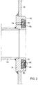
- the design and mode of operation of the pressurizable seal can be seen in FIG. 2.
- the ring 24, in which the seal 66 is arranged, is formed on the side opposite the closing body 14 with an undercut annular groove 76.
- the annular groove 76 is a cross-section formed as an open, circumferential groove rubber ring, the outer contour of which is dovetail-shaped.
- the outer contour of the seal 66 corresponds to the free cross section of the annular groove 76.
- the annular groove 76 is connected via a through hole 78 to a line (not shown) for a pressure medium.
- a liquid or preferably compressed air can be used as the pressure medium.
- the seal In the unloaded state, ie when no pressure medium has been introduced into the annular groove 76 through the bore 78, the seal has a shape in which it does not protrude beyond the end face 80 of the ring 24. As soon as, for example, compressed air is introduced into the annular groove 76 and thus into the cavity 82 of the seal 66, the stretches Seal 66 extends from and, since the expansion possibility is only given beyond the end face 80, the seal assumes an outwardly curved shape, as indicated in the lower part of FIG. 2. In this state, the seal presses on the closing surface 53 of the closing body plate 52, as a result of which, supported by the pressure prevailing in the pipe section 68, the closing body 14 presses against the end face 64 of the pipe section 30. The pressurized seal 66 ensures that a tight seal of the line adjoining the pipe section 32 is achieved with respect to the line adjoining the pipe section 44.
- a support spring is inserted, which is designed as a wound coil spring 84, which allows the inflation medium to pass between its turns.
- the coil spring 84 is wound from high strength spring wire with a wire gauge of about 1 mm, a pitch of about 1.5 mm and a space between adjacent turns of about 0.5 mm to be circumferential to its longitudinal axis to be able to absorb effective pressures of up to about 10 réellePa (10 bar). As shown in FIG. 2, the coil spring 84 need not rest with its entire outer circumference on the entire inner circumference of the ring seal 66.
- the helical spring 84 with its apex area which is directed towards the closing surface 53 of the closing body 14, rests on the inner circumference of the cavity 82 of the ring seal 66 inserted into the slide housing 12, in a state of the ring seal 66 when it is relieved of pressure their support walls are all around and undeformed, ie assumes its shape intended for the depressurized state.
- Fig. 3 shows schematically a pneumatic control of the pressure slide shown in Figs. 1 and 2.
- a compressed air source 90 is a 4/2-way valve 92, which can be operated manually, pneumatically or electrically, compressed air is fed into a line 94, which branches into a line 96, which leads to the pneumatic piston-cylinder unit 62 via a throttle check valve 98, and into a line 100, which via a 3/2 Directional control valve 102, which can be actuated mechanically, and leads via a throttle valve 104 to the pressurizable seal 66.
- a quick exhaust valve 106 is provided between the throttle valve 104 and the seal 66, via which the seal 66 is relieved when the closing body 14 is opened.
- the line 94 is relieved of pressure and the cylinder space 110 is pressurized. Due to the built-in throttle valve 98, a certain pressure must first build up before the piston 108 moves. This time delay is sufficient to relieve the seal 66 via the quick valve 106, so that no friction occurs on the seal 66 when the closing body 14 moves into the open position.
Abstract
Description
Die Erfindung betrifft einen Schieber für Rohrleitungen zum Transport von mit Feststoff beladenen, gasförmigen oder flüssigen Medien mit den im Oberbegriff des Anspruchs 1 angegebenen Merkmalen.The invention relates to a slide for pipelines for transporting solid, gaseous or liquid media with the features specified in the preamble of claim 1.
Ein derartiger Schieber ist aus der DE 36 06 236 A1 des Anmelders bekannt. Bei längerem Betrieb solcher bekannter Schieber hat sich herausgestellt, daß Feststoffteilchen bis zu einer Korngröße von etwa 100µ an der Ringdichtung vorbei durch den Druckquellenanschluß austreten und in das Entlastungsventil eindringen und dessen Funktion stören und es außer Funktion setzen können. Selbst ein Einsetzen der Ringdichtung in das Schiebergehäuse mit einem hochwirksamen Kleber konnte auf Dauer den Durchtritt solcher Feststoffteilchen an der Ringdichtung vorbei nicht verhindern, vielmehr erhöhte sich mit der Wirksamkeit des Klebers die Gefahr, daß die Ringdichtung selber durchbrach.Such a slide is known from
Aufgabe der Erfindung ist es, einen Schieber mit den im Oberbegriff des Anspruchs 1 angegebenen Merkmalen derart weiterzubilden, daß auch nach längerem Betrieb ein Durchtreten von selbst feinstkörnigsten Feststoffen an der Ringdichtung vorbei in den Druckquellenanschluß sicher verhindert ist, ohne daß hierfür aufwendige Zusatzarbeiten für ein besonders wirksames Verkleben der Ringdichtung erforderlich ist.The object of the invention is to develop a slide with the features specified in the preamble of claim 1 such that even after prolonged operation a passage of even the finest-grained solids past the ring seal past the pressure source connection is reliably prevented without the need for expensive additional work for a particular effective gluing of the ring seal is required.
Erfindungsgemäß wird diese Aufgabe durch die im Kennzeichen des Anspruchs 1 in Verbindung mit den in dessen Oberbegriff angegebenen Gattungsmerkmalen gelöst.According to the invention, this object is achieved by the features of the characterizing part of claim 1 in conjunction with the generic features specified in its preamble.
Längere Versuche mit erfindungsgemäßen Schiebern haben gezeigt, daß selbst bei Druckdifferenzen von 10⁶Pa (10 bar) zwischen dem druckentlasteten Druckquellenanschluß auf der einen Seite der Ringdichtung und dem bei geöffnetem Schieber strömenden Feststoffstrom auf der anderen Seite der Ringdichtung keine Feststoffe, selbst feinster Korngröße an der Ringdichtung vorbei in den Druckquellenanschluß gelangen.Longer tests with valves according to the invention have shown that even at pressure differences of 10⁶Pa (10 bar) between the pressure-relieved pressure source connection on one side of the ring seal and the flow of solids flowing on the other side of the ring seal when the valve is open, no solids, even the finest grain size on the ring seal get past into the pressure source connection.
Bei einer vorteilhaften Ausführungsform ist vorgesehen, daß die Stützfeder mit ihrem Scheitelbereich, der zur Schließfläche des Schließkörpers hin gerichtet ist, am Innenumfang des Hohlraums der ins Schiebergehäuse eingesetzten, druckentlasteten, an ihren Stützwänden rundum anliegenden, unverformten Ringdichtung stützend anliegt.In an advantageous embodiment it is provided that the support spring with its apex area, which is directed towards the closing surface of the closing body, rests on the inner circumference of the cavity of the pressure-relieved, undeformed ring seal which is in full contact with its support walls and which is in contact with the support walls.
Bevorzugt ist die Stützfeder eine gewickelte, zwischen ihren Windungen für das Aufblähmedium durchlässige Schraubenfeder, die vorteilhafterweise für die Aufnahme eines quer zu ihrer Längsachse auf ihren Umfang wirkenden Druckes bis zur Höhe von etwa 5 X 10⁵ bis 10⁶ Pa (10 bar) ausgelegt ist.The support spring is preferably a coiled helical spring which is permeable to the inflation medium between its windings and which is advantageously designed for receiving a pressure acting on its circumference transversely to its longitudinal axis up to a height of approximately 5 X 10⁵ to 10⁶ Pa (10 bar).
Weiterhin bevorzugt ist die Ringdichtung als eine im Querschnitt offene, umlaufende Rinne ausgebildet und in eine Ringnut des Schiebergehäuses eingesetzt, in welcher sie vorteilhafterweise klebfrei liegt.Furthermore, the ring seal is preferably designed as a circumferential channel which is open in cross section and is inserted into an annular groove in the valve housing, in which it advantageously lies without adhesive.
Andere vorteilhafte Weiterbildungen ergeben sich aus den Unteransprüchen.Other advantageous developments result from the subclaims.
Die Erfindung wird im folgenden anhand der Zeichnung beispielsweise erläutert. In dieser zeigt:
- Fig. 1
- eine Ausführungsform eines Schiebers im Längsschnitt,
- Fig. 2
- in vergrößertem Maßstab die Anordnung einer druckbeaufschlagbaren Dichtung und
- Fig. 3
- ein Schema einer Schiebersteuerung.
- Fig. 1
- an embodiment of a slide in longitudinal section,
- Fig. 2
- on an enlarged scale the arrangement of a pressurizable seal and
- Fig. 3
- a schematic of a slide control.
Fig. 1 zeigt im Längsschnitt einen Schieber 10, welcher im Verlauf einer nicht dargestellten Rohrleitung angeordnet ist. Durch die Rohrleitung werden gasförmige oder flüssige Medien transportiert, die einen mehr oder weniger großen Feststoffanteil aufweisen. Der Schieber 10 weist ein Schiebergehäuse 12 auf, in welchem ein Schließkörper 14 verschiebbar ist. Das Schiebergehäuse 12 besteht aus Blechplatten 16 und 18, die über am Rand umlaufende U-Profile 20 miteinander verbunden sind. Die Blechplatte 18 ist mit einer kreisförmigen Ausnehmung 22 versehen, in welche ein Ring 24 über eine umlaufende Schweißnaht 26 eingeschweißt ist. Die gegenüberliegende Platte 16 ist mit einer kreisförmigen Ausnehmung 28 versehen, in welche ein Rohrstück 30 über eine umlaufende Schweißnaht 31 befestigt ist. An dem Ring 24 ist ein Rohrstück 32 über eine Schweißnaht 34 befestigt. Der Ring 24 ist dazu mit einer Ausnehmung 36 ausgebildet. An dem dem Ring 24 gegenüberliegenden Ende ist an dem Rohrstück 32 ein Flansch 38 über eine Schweißnaht 40 angeschweißt, der zur Verbindung mit einer Rohrleitung dient.Fig. 1 shows in longitudinal section a
Das Rohrstück 30 ist an seinem dem Schiebergehäuse 12 gegenüberliegenden Ende mit einem Ring 42 versehen, in welchen ein Rohrstück 44 eingesetzt ist, dessen Durchmesser dem Durchmesser des Rohrstücks 32 entspricht. Das Rohrstück 44 ragt mit seinem dem Schiebergehäuse 12 hingerichteten Ende in das Rohrstück 30 hinein. An dem gegenüberliegenden Ende des Rohrstückes 44 ist ein Flansch 46 befestigt, welcher zur Verbindung mit einer anschließenden Rohrleitung dient. Der Durchmesser des Rohrstückes 30 ist größer als der des Rohrstückes 32 bzw. 44.The
An der Innenseite der Blechplatten 16 und 18 sind Führungsrippen 48 bzw. 50 angeordnet, welcher der Führung des Schließkörpers 14 dienen. Der Schließkörper 14, der aus zwei parallelen Platten 52 und 54 mit dazwischen angeordneten Distanzstücken 56 und 58 besteht, ist an einer Stange 60 angelenkt, welche über eine hydraulische oder pneumatische Kolbenzylindereinheit 62 betätigt wird. Die Außenseite der Schließkörperplatte 54 liegt an der abgeschrägten inneren Stirnfläche 64 des Rohrstückes 30 an. An der eine Schließfläche 53 bildenden Außenseite der gegenüberliegenden Schließkörperplatte 52 liegt bei geschlossenem Schieber eine Dichtung 66 an, die als druckbeaufschlagte Ringdichtung ausgebildet ist. Die Fließrichtung des mit Feststoffanteilen behafteten flüssigen oder gasförmigen Mediums ist durch den Pfeil 68 gekennzeichnet. Fig. 1 zeigt den Schieber im geschlossenen Zustand, d.h. in dem Rohrstück 32 vor der Schließkörperplatte 52 staut sich das zu transportierende Medium, während hinter der Schließkörperplatte 54 in den Rohrstücken 30 und 44 kein Druck des Mediums mehr vorliegt. Zur Verstärkung der Verbindung zwischen dem Schiebergehäuse 12 und den Rohrstücken 32 und 30 sind Verstärkungsrippen 70, 72, 74 vorgesehen.On the inside of the
Die Ausbildung und Wirkungsweise der druckbeaufschlagbaren Dichtung ist aus Fig. 2 ersichtlich. Der Ring 24, in welchem die Dichtung 66 angeordnet ist, ist an der dem Schließkörper 14 gegenüberliegenden Seite mit einer hinterschnittenen Ringnut 76 ausgebildet. In die Ringnut 76 ist ein im Querschnitt als offene, umlaufende Rinne ausgebildeter Gummiring, dessen Außenkontur schwalbenschwanzförmig ist, eingeklebt. Die Außenkontur der Dichtung 66 entspricht dem freien Querschnitt der Ringnut 76. Die Ringnut 76 steht über eine Durchgangsbohrung 78 mit einer nicht dargestellten Leitung für ein Druckmedium in Verbindung. Als Druckmedium kann eine Flüssigkeit oder vorzugsweise Druckluft verwendet werden. Im nicht beaufschlagten Zustand, d.h. wenn kein Druckmedium durch die Bohrung 78 in die Ringnut 76 eingeleitet wurde, weist die Dichtung eine Gestalt auf, in welcher sie nicht über die Stirnfläche 80 des Ringes 24 hervorsteht. Sobald beispielsweise Druckluft in die Ringnut 76 und damit in den Hohlraum 82 der Dichtung 66 eingeleitet wird, dehnt die Dichtung 66 sich aus und, da die Ausdehnungsmöglichkeit lediglich über die Stirnfläche 80 hinaus gegeben ist, nimmt die Dichtung eine nach außen gekrümmte Gestalt an, wie sie im unteren Teil von Fig. 2 angedeutet ist. In diesem Zustand drückt die Dichtung auf die Schließfläche 53 der Schließkörperplatte 52, wodurch, unterstützt durch den in dem Rohrstück 68 herrschenden Druck, der Schließkörper 14 gegen die Stirnfläche 64 des Rohrstückes 30 drückt. Durch die druckbeaufschlagte Dichtung 66 wird gewährleistet, daß ein dichter Abschluß der an dem Rohrstück 32 anschließenden Leitung gegenüber der sich an das Rohrstück 44 anschließenden Leitung erreicht wird.The design and mode of operation of the pressurizable seal can be seen in FIG. 2. The
In den Hohlraum 82 der Ringdichtung 66 ist eine Stützfeder eingesetzt, die als gewickelte Schraubenfeder 84 ausgebildet ist, die das Aufblähmedium zwischen ihren Windungen durchtreten läßt. Bei der dargestellten Ausführungsform ist die Schraubenfeder 84 aus hochfestem Federdraht mit einer Drahtstärke von etwa 1 mm, einer Steigung von etwa 1,5 mm und einem Zwischenraum zwischen benachbarten Windungen von etwa 0,5 mm gewickelt worden, um quer zu ihrer Längsachse auf ihren Umfang wirkende Drücke bis zur Höhe von etwa 10⁶Pa (10 bar) aufnehmen zu können. Wie in Fig. 2 gezeigt ist, braucht die Schraubenfeder 84 nicht mit ihrem gesamten Außenumfang am gesamten Innenumfang der Ringdichtung 66 anzuliegen. Es reicht, wenn die Schraubenfeder 84 mit ihrem Scheitelbereich, der zur Schließfläche 53 des Schließkörpers 14 hin gerichtet ist, am Innenumfang des Hohlraums 82 der ins Schiebergehäuse 12 eingesetzten Ringdichtung 66 stützend anliegt, und zwar in einem Zustand der Ringdichtung 66, wenn diese druckentlastet an ihren Stützwänden rundum anliegt und unverformt ist, d.h. ihre für den drucklosen Zustand vorgesehene Form einnimmt.In the
Fig. 3 zeigt schematisch eine pneumatische Steuerung des in den Fig. 1 und 2 dargestellten Druckschiebers. Von einer Druckluftquelle 90 wird über ein 4/2-Wegeventil 92, welches von Hand, pneumatisch oder elektrisch betätigt werden kann, Druckluft in eine Leitung 94 eingespeist, die sich verzweigt in eine Leitung 96, die über ein Drosselrückschlagventil 98 zu der pneumatischen Kolbenzylindereinheit 62 führt, und in eine Leitung 100, die über ein 3/2-Wegeventil 102, das mechanisch betätigbar ist, und über ein Drosselventil 104 zu der druckbeaufschlagbaren Dichtung 66 führt. Zwischen dem Drosselventil 104 und der Dichtung 66 ist ein Schnellentlüftungsventil 106 vorgesehen, über welches bei Öffnen des Schließkörpers 14 die Dichtung 66 entlastet wird. Sobald über das Ventil 92 Druckluft eingespeist wird, wird der Kolben 108 der Kolbenzylindereinheit 62 nach unten verschoben, wodurch der Schließkörper 14 in die Schließstellung gebracht wird. Sobald der Schließkörper 14 seine Schließstellung eingenommen hat, wird über das Ventil 102 Druckluft in die Dichtung 66 geleitet, so daß diese aufgeblasen wird und sich dichtend an die Seitenfläche des Schließkörpers 14 anlegt. Während des Verschiebens des Kolbens 108 in die Schließstellung erfolgt eine Entlüftung des vor dem Kolben liegenden Zylinderraumes 110 über eine Leitung 112. Wenn der Schieber öffnen soll, wird über die Leitung 112 durch Umsteuerung des Ventils 92 Druckluft in den Zylinderraum 110 eingeleitet, so daß der Kolben 108 nach oben schieben kann und dabei den Schließkörper 14 mitnimmt.Fig. 3 shows schematically a pneumatic control of the pressure slide shown in Figs. 1 and 2. From a
Bei der Einleitung des Öffnungsvorganges wird die Leitung 94 druckentlastet und der Zylinderraum 110 unter Druck gesetzt. Durch das eingebaute Drosselventil 98 muß sich zuerst ein gewisser Druck aufbauen, bevor sich der Kolben 108 bewegt. Diese Zeitverzögerung reicht aus, um die Dichtung 66 über das Schnellventil 106 zu entlasten, so daß bei der Bewegung des Schließkörpers 14 in die offenstellung keine Reibung an der Dichtung 66 auftritt.When the opening process is initiated, the
- 1010th
- SchieberSlider
- 1212th
- SchiebergehäuseValve housing
- 1414
- SchließkörperClosing body
- 1616
- BlechplatteSheet metal plate
- 1818th
- BlechplatteSheet metal plate
- 2020th
- U-ProfilU profile
- 2222
- kreisförmige Ausnehmungcircular recess
- 2424th
- Ringring
- 2626
- SchweißnahtWeld
- 2828
- kreisförmige Ausnehmungcircular recess
- 3030th
- RohrstückPipe piece
- 3131
- SchweißnahtWeld
- 3232
- RohrstückPipe piece
- 3434
- SchweißnahtWeld
- 3636
- AusnehmungRecess
- 3838
- Flanschflange
- 4040
- SchweißnahtWeld
- 4242
- Ringring
- 4444
- RohrstückPipe piece
- 4646
- Flanschflange
- 4848
- FührungsrippeGuide rib
- 5050
- FührungsrippeGuide rib
- 5252
- Platteplate
- 5454
- Platteplate
- 5656
- DistanzstückSpacer
- 5858
- DistanzstückSpacer
- 6060
- Stangepole
- 6262
- ZylindereinheitCylinder unit
- 6464
- abgeschrägte Stirnflächebeveled face
- 6666
- RingdichtungRing seal
- 6868
- Pfeilarrow
- 7070
- VerstärkungsrippeReinforcement rib
- 7272
- VerstärkungsrippeReinforcement rib
- 7474
- VerstärkungsrippeReinforcement rib
- 7676
- RingnutRing groove
- 7878
- Bohrungdrilling
- 8080
- Stirnfläche (24)End face (24)
- 8282
- Hohlraumcavity
- 8484
- StützfederSupport spring
- 9090
- DruckquellePressure source
- 9292
- VentilValve
- 9494
- Leitungmanagement
- 9696
- Leitungmanagement
- 9898
- Rückschlagventilcheck valve
- 100100
- Leitungmanagement
- 102102
- VentilValve
- 104104
- DrosselventilThrottle valve
- 106106
- EntlüftungsventilVent valve
- 108108
- Kolbenpiston
- 110110
- ZylinderraumCylinder space
- 112112
- Leitungmanagement
Claims (11)
Applications Claiming Priority (2)
| Application Number | Priority Date | Filing Date | Title |
|---|---|---|---|
| DE4329856A DE4329856C1 (en) | 1993-09-03 | 1993-09-03 | Slider |
| DE4329856 | 1993-09-03 |
Publications (2)
| Publication Number | Publication Date |
|---|---|
| EP0646742A1 true EP0646742A1 (en) | 1995-04-05 |
| EP0646742B1 EP0646742B1 (en) | 1997-01-02 |
Family
ID=6496800
Family Applications (1)
| Application Number | Title | Priority Date | Filing Date |
|---|---|---|---|
| EP94113336A Expired - Lifetime EP0646742B1 (en) | 1993-09-03 | 1994-08-25 | Gate valve with expandable seal |
Country Status (4)
| Country | Link |
|---|---|
| US (1) | US5618024A (en) |
| EP (1) | EP0646742B1 (en) |
| DE (2) | DE4329856C1 (en) |
| ES (1) | ES2098837T3 (en) |
Cited By (4)
| Publication number | Priority date | Publication date | Assignee | Title |
|---|---|---|---|---|
| NL1016807C2 (en) * | 2000-12-06 | 2002-06-07 | G C De Jong Systems B V | Slide closure is provided with closure plate movable by motor drive backwards and forwards in conduits between open and closed state, being provided with seal, which is elastically expandable and shrinkable between unsealed and sealed state |
| WO2005017921A1 (en) * | 2003-08-13 | 2005-02-24 | Belgonucleaire Sa | Sealing device for the outer surface of a nuclear fuel cladding |
| WO2015165712A1 (en) * | 2014-04-29 | 2015-11-05 | Z+J Technologies Gmbh | Conduit slider for chemical and petrochemical systems |
| CN113464672A (en) * | 2021-08-04 | 2021-10-01 | 凯瑞特阀业有限公司 | Self-expansion gate valve |
Families Citing this family (6)
| Publication number | Priority date | Publication date | Assignee | Title |
|---|---|---|---|---|
| DE10314372A1 (en) * | 2003-03-28 | 2004-10-28 | Horst Schmidt | Device and method for sealing a passage opening |
| WO2017158077A1 (en) * | 2016-03-16 | 2017-09-21 | Fmc Kongsberg Subsea As | Valve assembly and method for operation of seal in gate valve assembly |
| CN108884951B (en) * | 2016-04-08 | 2021-04-16 | Vat控股公司 | Closure device |
| CN106763826A (en) * | 2017-03-15 | 2017-05-31 | 奉化市智新仪表科技有限公司 | A kind of valve plate and valve seat insert of gas-flow closure butterfly valve |
| CN206723534U (en) * | 2017-05-04 | 2017-12-08 | 浙江三花汽车零部件有限公司 | Heat control valve |
| WO2020144303A1 (en) * | 2019-01-11 | 2020-07-16 | Volker Wurzer | Shut-off valve |
Citations (4)
| Publication number | Priority date | Publication date | Assignee | Title |
|---|---|---|---|---|
| CH471994A (en) * | 1967-01-13 | 1969-04-30 | Martin Westenberg Fa | Flat slide |
| US3711062A (en) * | 1970-11-02 | 1973-01-16 | C Kirkwood | Expandable seal gate valve |
| DE3606236A1 (en) * | 1986-02-14 | 1987-08-27 | Martin Westenberg | SLIDER |
| EP0587006A1 (en) * | 1992-09-09 | 1994-03-16 | Fmc Corporation | Re-energizable valve and valve seats |
Family Cites Families (4)
| Publication number | Priority date | Publication date | Assignee | Title |
|---|---|---|---|---|
| US3445087A (en) * | 1966-09-30 | 1969-05-20 | Hills Mccanna Co | High pressure ball valve |
| US3642248A (en) * | 1969-05-07 | 1972-02-15 | Allen & Co Fof Proprietary Fun | Sealing mechanism |
| US4137935A (en) * | 1976-02-11 | 1979-02-06 | Macawber Engineering Limited | Valve assembly |
| US4145026A (en) * | 1977-08-22 | 1979-03-20 | Chronister Clyde H | Valve with self-actuating fluid seal |
-
1993
- 1993-09-03 DE DE4329856A patent/DE4329856C1/en not_active Expired - Lifetime
-
1994
- 1994-08-25 ES ES94113336T patent/ES2098837T3/en not_active Expired - Lifetime
- 1994-08-25 DE DE59401460T patent/DE59401460D1/en not_active Expired - Fee Related
- 1994-08-25 EP EP94113336A patent/EP0646742B1/en not_active Expired - Lifetime
-
1995
- 1995-08-15 US US08/515,220 patent/US5618024A/en not_active Expired - Fee Related
Patent Citations (4)
| Publication number | Priority date | Publication date | Assignee | Title |
|---|---|---|---|---|
| CH471994A (en) * | 1967-01-13 | 1969-04-30 | Martin Westenberg Fa | Flat slide |
| US3711062A (en) * | 1970-11-02 | 1973-01-16 | C Kirkwood | Expandable seal gate valve |
| DE3606236A1 (en) * | 1986-02-14 | 1987-08-27 | Martin Westenberg | SLIDER |
| EP0587006A1 (en) * | 1992-09-09 | 1994-03-16 | Fmc Corporation | Re-energizable valve and valve seats |
Cited By (6)
| Publication number | Priority date | Publication date | Assignee | Title |
|---|---|---|---|---|
| NL1016807C2 (en) * | 2000-12-06 | 2002-06-07 | G C De Jong Systems B V | Slide closure is provided with closure plate movable by motor drive backwards and forwards in conduits between open and closed state, being provided with seal, which is elastically expandable and shrinkable between unsealed and sealed state |
| WO2005017921A1 (en) * | 2003-08-13 | 2005-02-24 | Belgonucleaire Sa | Sealing device for the outer surface of a nuclear fuel cladding |
| WO2015165712A1 (en) * | 2014-04-29 | 2015-11-05 | Z+J Technologies Gmbh | Conduit slider for chemical and petrochemical systems |
| US9777845B2 (en) | 2014-04-29 | 2017-10-03 | Z&J Technologies Gmbh | Conduit slider for chemical and petrochemical systems |
| DE102014106001B4 (en) | 2014-04-29 | 2022-09-29 | Z & J Technologies Gmbh | Draft tube gate valves for chemical and petrochemical plants |
| CN113464672A (en) * | 2021-08-04 | 2021-10-01 | 凯瑞特阀业有限公司 | Self-expansion gate valve |
Also Published As
| Publication number | Publication date |
|---|---|
| DE4329856C1 (en) | 1995-04-13 |
| DE59401460D1 (en) | 1997-02-13 |
| US5618024A (en) | 1997-04-08 |
| EP0646742B1 (en) | 1997-01-02 |
| ES2098837T3 (en) | 1997-05-01 |
Similar Documents
| Publication | Publication Date | Title |
|---|---|---|
| DE3606236C2 (en) | ||
| DE2232583C2 (en) | Mandrel | |
| DE3142768C2 (en) | Internal closure device for a pipeline | |
| EP0646742B1 (en) | Gate valve with expandable seal | |
| EP0507127B1 (en) | Pipe switch | |
| EP1126938B1 (en) | Bordering and/or crease-closing machine and method for operating the same | |
| DE102008017099B4 (en) | flat slide | |
| DE102015110113B4 (en) | Gate valves | |
| DE2403773C3 (en) | Drain valve with vacuum seal for rail tank cars | |
| EP2460639B1 (en) | Device for blow moulding containers | |
| EP2127851B1 (en) | Device and method for expanding containers with seal at the opening of the container | |
| DE4421696C1 (en) | Single layer conduit for abrasive substances | |
| DE1957443A1 (en) | Drive device | |
| DE3221984A1 (en) | Hydraulic cylinder | |
| DE924126C (en) | Hydraulic vehicle steering, especially for heavy-duty vehicles | |
| DE2719164A1 (en) | Large gas mains gate valve - with movable seat applied by compression springs and released by bellows | |
| DE3033739A1 (en) | Pressure booster for high pressure generator - has pressure switches for low pressure fluid feed, actuated by low pressure piston | |
| AT355536B (en) | HYDRAULIC PIT STAMP | |
| DE1250217B (en) | Device for sealing the detachable closure member of pressure vessels Rohrleitun gene or fittings | |
| DE2554594A1 (en) | CONTROL VALVE FOR HYDRAULICALLY ACTUATED TIPPER VEHICLES | |
| DE3706590C2 (en) | Device for temporarily closing the cross section of a gas or liquid carrying pipeline | |
| EP0839961B1 (en) | Barriers for traffic areas | |
| DE10229964C1 (en) | Blocking device for pressurized medium line uses 2 diagonally opposing circular segment closure elements | |
| EP0672853A1 (en) | Slide valve for pipelines | |
| DE102009025092A1 (en) | Valve cartridge for dual check valve of punching tool for stope support in deep mining, has control piston with flow opening in piston head, and auxiliary piston arranged inside control piston between piston head and end of valve piston |
Legal Events
| Date | Code | Title | Description |
|---|---|---|---|
| PUAI | Public reference made under article 153(3) epc to a published international application that has entered the european phase |
Free format text: ORIGINAL CODE: 0009012 |
|
| AK | Designated contracting states |
Kind code of ref document: A1 Designated state(s): CH DE ES FR GB IT LI NL |
|
| 17P | Request for examination filed |
Effective date: 19950511 |
|
| GRAG | Despatch of communication of intention to grant |
Free format text: ORIGINAL CODE: EPIDOS AGRA |
|
| 17Q | First examination report despatched |
Effective date: 19960301 |
|
| GRAH | Despatch of communication of intention to grant a patent |
Free format text: ORIGINAL CODE: EPIDOS IGRA |
|
| GRAH | Despatch of communication of intention to grant a patent |
Free format text: ORIGINAL CODE: EPIDOS IGRA |
|
| GRAA | (expected) grant |
Free format text: ORIGINAL CODE: 0009210 |
|
| AK | Designated contracting states |
Kind code of ref document: B1 Designated state(s): CH DE ES FR GB IT LI NL |
|
| REG | Reference to a national code |
Ref country code: CH Ref legal event code: EP |
|
| GBT | Gb: translation of ep patent filed (gb section 77(6)(a)/1977) |
Effective date: 19970102 |
|
| REF | Corresponds to: |
Ref document number: 59401460 Country of ref document: DE Date of ref document: 19970213 |
|
| ET | Fr: translation filed | ||
| ITF | It: translation for a ep patent filed |
Owner name: 0403;03MIFSOCIETA' ITALIANA BREVETTI S.P |
|
| REG | Reference to a national code |
Ref country code: CH Ref legal event code: NV Representative=s name: PATENTANWAELTE SCHAAD, BALASS, MENZL & PARTNER AG |
|
| REG | Reference to a national code |
Ref country code: ES Ref legal event code: FG2A Ref document number: 2098837 Country of ref document: ES Kind code of ref document: T3 |
|
| PLBE | No opposition filed within time limit |
Free format text: ORIGINAL CODE: 0009261 |
|
| STAA | Information on the status of an ep patent application or granted ep patent |
Free format text: STATUS: NO OPPOSITION FILED WITHIN TIME LIMIT |
|
| 26N | No opposition filed | ||
| PGFP | Annual fee paid to national office [announced via postgrant information from national office to epo] |
Ref country code: GB Payment date: 20010807 Year of fee payment: 8 |
|
| PGFP | Annual fee paid to national office [announced via postgrant information from national office to epo] |
Ref country code: FR Payment date: 20010822 Year of fee payment: 8 |
|
| PGFP | Annual fee paid to national office [announced via postgrant information from national office to epo] |
Ref country code: CH Payment date: 20010824 Year of fee payment: 8 |
|
| PGFP | Annual fee paid to national office [announced via postgrant information from national office to epo] |
Ref country code: NL Payment date: 20010827 Year of fee payment: 8 |
|
| PGFP | Annual fee paid to national office [announced via postgrant information from national office to epo] |
Ref country code: ES Payment date: 20010829 Year of fee payment: 8 |
|
| REG | Reference to a national code |
Ref country code: GB Ref legal event code: IF02 |
|
| PG25 | Lapsed in a contracting state [announced via postgrant information from national office to epo] |
Ref country code: GB Free format text: LAPSE BECAUSE OF NON-PAYMENT OF DUE FEES Effective date: 20020825 |
|
| PG25 | Lapsed in a contracting state [announced via postgrant information from national office to epo] |
Ref country code: ES Free format text: LAPSE BECAUSE OF NON-PAYMENT OF DUE FEES Effective date: 20020826 |
|
| PG25 | Lapsed in a contracting state [announced via postgrant information from national office to epo] |
Ref country code: LI Free format text: LAPSE BECAUSE OF NON-PAYMENT OF DUE FEES Effective date: 20020831 Ref country code: CH Free format text: LAPSE BECAUSE OF NON-PAYMENT OF DUE FEES Effective date: 20020831 |
|
| PGFP | Annual fee paid to national office [announced via postgrant information from national office to epo] |
Ref country code: DE Payment date: 20021028 Year of fee payment: 9 |
|
| PG25 | Lapsed in a contracting state [announced via postgrant information from national office to epo] |
Ref country code: NL Free format text: LAPSE BECAUSE OF NON-PAYMENT OF DUE FEES Effective date: 20030301 |
|
| REG | Reference to a national code |
Ref country code: CH Ref legal event code: PL |
|
| GBPC | Gb: european patent ceased through non-payment of renewal fee |
Effective date: 20020825 |
|
| PG25 | Lapsed in a contracting state [announced via postgrant information from national office to epo] |
Ref country code: FR Free format text: LAPSE BECAUSE OF NON-PAYMENT OF DUE FEES Effective date: 20030430 |
|
| NLV4 | Nl: lapsed or anulled due to non-payment of the annual fee |
Effective date: 20030301 |
|
| REG | Reference to a national code |
Ref country code: FR Ref legal event code: ST |
|
| PG25 | Lapsed in a contracting state [announced via postgrant information from national office to epo] |
Ref country code: DE Free format text: LAPSE BECAUSE OF NON-PAYMENT OF DUE FEES Effective date: 20040302 |
|
| REG | Reference to a national code |
Ref country code: ES Ref legal event code: FD2A Effective date: 20030912 |
|
| PG25 | Lapsed in a contracting state [announced via postgrant information from national office to epo] |
Ref country code: IT Free format text: LAPSE BECAUSE OF NON-PAYMENT OF DUE FEES Effective date: 20050825 |