EP0646495A1 - Head lamp device for motor vehicle - Google Patents
Head lamp device for motor vehicle Download PDFInfo
- Publication number
- EP0646495A1 EP0646495A1 EP94114872A EP94114872A EP0646495A1 EP 0646495 A1 EP0646495 A1 EP 0646495A1 EP 94114872 A EP94114872 A EP 94114872A EP 94114872 A EP94114872 A EP 94114872A EP 0646495 A1 EP0646495 A1 EP 0646495A1
- Authority
- EP
- European Patent Office
- Prior art keywords
- head lamp
- housing
- vent
- reflector
- vent pipe
- Prior art date
- Legal status (The legal status is an assumption and is not a legal conclusion. Google has not performed a legal analysis and makes no representation as to the accuracy of the status listed.)
- Granted
Links
- 230000003287 optical effect Effects 0.000 claims abstract description 13
- 238000013022 venting Methods 0.000 claims 6
- XLYOFNOQVPJJNP-UHFFFAOYSA-N water Chemical compound O XLYOFNOQVPJJNP-UHFFFAOYSA-N 0.000 description 5
- 238000000034 method Methods 0.000 description 3
- 238000007599 discharging Methods 0.000 description 2
- 238000012986 modification Methods 0.000 description 2
- 230000004048 modification Effects 0.000 description 2
- 239000012141 concentrate Substances 0.000 description 1
- 238000010276 construction Methods 0.000 description 1
- 238000004904 shortening Methods 0.000 description 1
- 239000012780 transparent material Substances 0.000 description 1
Images


Classifications
-
- B—PERFORMING OPERATIONS; TRANSPORTING
- B60—VEHICLES IN GENERAL
- B60Q—ARRANGEMENT OF SIGNALLING OR LIGHTING DEVICES, THE MOUNTING OR SUPPORTING THEREOF OR CIRCUITS THEREFOR, FOR VEHICLES IN GENERAL
- B60Q1/00—Arrangement of optical signalling or lighting devices, the mounting or supporting thereof or circuits therefor
- B60Q1/02—Arrangement of optical signalling or lighting devices, the mounting or supporting thereof or circuits therefor the devices being primarily intended to illuminate the way ahead or to illuminate other areas of way or environments
- B60Q1/04—Arrangement of optical signalling or lighting devices, the mounting or supporting thereof or circuits therefor the devices being primarily intended to illuminate the way ahead or to illuminate other areas of way or environments the devices being headlights
- B60Q1/06—Arrangement of optical signalling or lighting devices, the mounting or supporting thereof or circuits therefor the devices being primarily intended to illuminate the way ahead or to illuminate other areas of way or environments the devices being headlights adjustable, e.g. remotely-controlled from inside vehicle
- B60Q1/068—Arrangement of optical signalling or lighting devices, the mounting or supporting thereof or circuits therefor the devices being primarily intended to illuminate the way ahead or to illuminate other areas of way or environments the devices being headlights adjustable, e.g. remotely-controlled from inside vehicle by mechanical means
- B60Q1/0683—Adjustable by rotation of a screw
-
- B—PERFORMING OPERATIONS; TRANSPORTING
- B62—LAND VEHICLES FOR TRAVELLING OTHERWISE THAN ON RAILS
- B62J—CYCLE SADDLES OR SEATS; AUXILIARY DEVICES OR ACCESSORIES SPECIALLY ADAPTED TO CYCLES AND NOT OTHERWISE PROVIDED FOR, e.g. ARTICLE CARRIERS OR CYCLE PROTECTORS
- B62J6/00—Arrangement of optical signalling or lighting devices on cycles; Mounting or supporting thereof; Circuits therefor
- B62J6/02—Headlights
- B62J6/022—Headlights specially adapted for motorcycles or the like
- B62J6/025—Headlights specially adapted for motorcycles or the like characterised by vertical adjustment of the light beam direction, e.g. to compensate for heavy loads
-
- B—PERFORMING OPERATIONS; TRANSPORTING
- B62—LAND VEHICLES FOR TRAVELLING OTHERWISE THAN ON RAILS
- B62J—CYCLE SADDLES OR SEATS; AUXILIARY DEVICES OR ACCESSORIES SPECIALLY ADAPTED TO CYCLES AND NOT OTHERWISE PROVIDED FOR, e.g. ARTICLE CARRIERS OR CYCLE PROTECTORS
- B62J6/00—Arrangement of optical signalling or lighting devices on cycles; Mounting or supporting thereof; Circuits therefor
- B62J6/02—Headlights
- B62J6/022—Headlights specially adapted for motorcycles or the like
- B62J6/026—Headlights specially adapted for motorcycles or the like characterised by the structure, e.g. casings
-
- F—MECHANICAL ENGINEERING; LIGHTING; HEATING; WEAPONS; BLASTING
- F21—LIGHTING
- F21S—NON-PORTABLE LIGHTING DEVICES; SYSTEMS THEREOF; VEHICLE LIGHTING DEVICES SPECIALLY ADAPTED FOR VEHICLE EXTERIORS
- F21S45/00—Arrangements within vehicle lighting devices specially adapted for vehicle exteriors, for purposes other than emission or distribution of light
- F21S45/30—Ventilation or drainage of lighting devices
- F21S45/33—Ventilation or drainage of lighting devices specially adapted for headlamps
Definitions
- the present invention relates to a head lamp device for a motor vehicle.
- a two-bulb head lamp device for a motor vehicle is set forth in the present inventor's co-pending Japanese Laid-open Patent publication No. 5-85435.
- the proposed head lamp device comprises two bulbs and a pair of reflecting mirrors which are accommodated in one housing. Water vapor in the housing is evaporated by the heat of the bulbs and tends to be attached to the inner surface of a lens, thereby frosting the lens. Head lamp devices designed to solve this problem have an opening defined in the housing for discharging heat and water vapor out of the housing.
- a head lamp device for a motor vehicle as disclosed in Figure 3 of Japanese Laid-open Utility Model publication No. 4-135105 has a J-shaped vent pipe (460) disposed on the back of a housing for discharging heat or the like.
- the optical axis can be adjusted vertically by rotating an optical axis adjusting mechanism 5A shown in Figure 3.
- head lamp devices have an optical axis adjusting mechanism.
- An optical axis adjustment will hereinafter be referred to as "aiming” and an optical axis adjusting mechanism as the "aiming mechanism.”
- An aiming rod or aiming bolt corresponding to the component 50A in Figure 3 of Japanese Laid-open Utility Model Publication No. 4-135105, is considerably long. If the aiming rod was short, then a tool for turning the aiming rod would interfere with the i-shaped vent pipe, and would damage or dismount the J-shaped vent pipe when operated in error. Therefore, the aiming rod is of a sufficient length. The long aiming rod, however, requires a space behind the head lamp, and such a space is not preferable from the standpoint of positioning devices in a compact arrangement.
- a head lamp device for a motor vehicle has an aiming mechanism for adjusting the optical axis disposed near a vent pipe, and a guard rib projecting from a housing and separating the aiming mechanism and the vent pipe from each other.
- the reflector has a plurality of reflector surfaces having a plurality of types of reflecting angles, and a lens, disposed in front of the reflector, is substantially transparent.
- the guard rib has a height which is substantially the same as the height at which the vent pipe is attached.
- the lens for use with the reflector may be substantially transparent.
- the substantially transparent lens has a good appearance and does not need any lens cuts.
- water is applied to the inner surface of the lens, then it is frosted much more than a conventional lens with lens cuts. The lens is prevented from being frosted by ventilating the housing with the vent hole and the vent pipe.
- a tool such as a screwdriver used for aiming is less liable to hit the vent pipe.
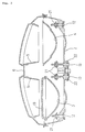
- Figure 1 is a front elevational view of a head lamp device according to the present invention.
- the head lamp device 1 has a first reflector 3, a second reflector 4, and intermediate tubes 5, see Figure 3 which are accommodated in a housing 2, and a lens 4 fitted over the housing 2.
- the head lamp device 1 is mounted on a vehicle body by screws (not shown) extending through respective attachment arms 7 threadedly into the vehicle body.
- the first reflector 3 has a plurality of reflector surfaces 3a, 3b, 3c, having a plurality of types of reflecting angles, so that the first reflector 3 has Fresnel surface irregularities on its reflecting surface.
- the reflector surfaces 3a, 3b, 3c, of the reflector 3 are effective to distribute light, and the lens 6 is not required to have lens cuts. Since the lens 6 does not need any lens cuts, the lens 6 has an improved appearance.
- the second reflector 4 also has a plurality of reflector surfaces 3a, 3b, 3c, having a plurality of types of reflecting angles. However, the second reflector 4 has rougher Fresnel surface irregularities than the first reflector 3.
- the lens 6 is made of a transparent material.
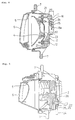
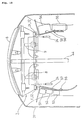
- FIG. 2 is a rear elevational view of the head lamp device according to the present invention.
- the head lamp device has a terminal 8a of a first bulb 8, a terminal 9a of a second bulb 9, first through third adjustment screws 11, 12, 13 of an aiming mechanism are provided, and left and right vent pipes 14, 15 and a central vent pipe 16 which are mounted on the back of the housing 2.
- arcuate guard ribs 18 project rearwardly from the housing 2 above the respective left and right vent pipes 14, 15.
- Figure 3 is a cross-sectional view taken along line 3-3 of Figure 2.
- the intermediate tubes 5 are disposed in front of the first and second reflectors 3, 4 in the housing 2.
- An inner lens 19 is mounted directly on the first reflector 3.
- Nut-like sliders 21 are attached to the second and third adjustment screws 12, 13, and the first and second reflectors 3, 4 are attached to the sliders 21.
- the sliders 21 are shown as being separate from the reflectors 3, 4 because of the position of the section, but they are actually mechanically coupled to each other. See Figure 4.
- FIG 4 is a cross-sectional view taken along line 4-4 of Figure 2.
- the right vent pipe 15 comprises a substantially L-shape rubber tube having labyrinth projections 15a therein.
- the right vent pipe 15 is fitted over and resiliently attached to a boss 2b which surrounds a vent hole 2a defined in the back of the housing 2.
- the right vent pipe 15 has an opening positioned on its lower end. Therefore, water or the like is prevented from entering the right vent pipe 15 from above or laterally. Water from below is effectively blocked by the labyrinth projections 15a.
- the height H1 is substantially the same as a height H2 at which the right vent pipe 15 is properly attached.
- the reflector 4 is tilted through the sliders 21 and an intermediate plate 23 for vertical angular adjustment.
- FIG. 5 is a cross-sectional view taken along line 5-5 of Figure 2.
- a crown gear 22 is mounted on the proximal end of the third adjustment screw 13.
- the third adjustment screw 13 can be turned.
- a pair of relatively low left and right tool guide ribs 25 project from the housing 2 below the third adjustment screw 13.
- the screwdriver may be inserted between the tool guide ribs 25.
- a rib 26 projects from the housing 2 in surrounding relationship to upper portions of the crown gears 22, see also Figure 2.
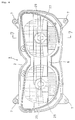
- Figure 6 is a view showing another embodiment of the structure shown in Figure 1.
- First and second reflectors 27, 28 are in axial symmetry, and have identical Fresnel surface irregularity patterns on their reflecting surfaces.
- the reflectors 27, 28 do not have inner lenses described above with reference to Figure 3.
- Subreflectors 29 are combined with bulbs 8.
- the subreflectors 29 serve to reverse light directed directly forwardly so as to concentrate on the reflector 27, thus increasing the intensity of light.
- Figure 7 is a cross-sectional view taken along line 7-7 of Figure 6.
- the first bulb 8 is mounted centrally on the first reflector 27. Light emitted from the first bulb 8 is reflected by the first reflector 27, adjusted in its profile by the intermediate tube 5, and emitted through the lens 6.
- the second reflector 28 operates in the same manner as described above.
- FIG. 8 is a fragmentary front elevational view of a motorcycle which is equipped with the head lamp device according to the present invention.
- the head lamp device 1 is fitted substantially centrally in a front cowl 31.
- First and third adjustment screws 11, 13 are provided together with vent pipes 14, 15, 16, and guard ribs 18.
- a screen 32 is mounted on an upper portion of the front cowl 31, and a horn 33 is mounted on a lower portion of the front cowl 31.
- the front cowl 31 has small holes 34 and air inlet holes 35 which are defined in each of the left and right portions thereof.
- the small holes 34 are defined to reduce air resistance caused by ram air which is laterally applied when the motorcycle is making a turn. Since the air resistance is reduced by the small holes 34, the motorcycle can be stably maneuvered.
- the air inlet holes 35 serve as openings for introducing air into a head pipe and an air cleaner.
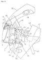
- FIG. 9 is a fragmentary side elevational view of the motorcycle with the head lamp device according to the present invention.
- a triangular front cowl stay 44 is fastened by bolts to a head pipe 43 which is fixed to front portions of a main frame 41 and an engine hanger frame 42.
- the front cowl 31 is secured to a front end of the triangular front cowl stay 44 by screws 45.
- the head lamp device 1 is fixed to the front cowl 31 by screws 46.
- a position lamp 47 is attached to the front cowl 31.
- a meter 48 is mounted on a front upper portion of the front cowl stay 44.
- the front cowl 31 has rearview mirror attachment seats 49 and flashing indicator attachment seats 50.
- FIG 10 is a fragmentary plan view of the motorcycle with the head lamp device according to the present invention.
- a left stay 57 is secured by a clip 56 to an inner surface of the cowl 31 on the left-hand side of the front cowl stay 44 as viewed by the driver of the motorcycle.
- a flashing indicator relay 51 To the left stay 57, there are successively attached a flashing indicator relay 51, a head lamp high position relay 52, and a head lamp low position relay 53.
- a right stay 58 is secured by a clip 56 to an inner surface of the cowl 31 on the right-hand side of the front cowl stay 44.
- a coupler cluster plate 54 and a fuse box 55 are successively mounted on the right stay 58.
- the aiming mechanism is composed of the first through third adjustment screws 11, 13 and the sliders 21.
- first and second adjustment screws 11, 12 may be turned to the left or right with the screwdriver 24 for cross-slotted screw heads in Figure 10.
- first and third adjustment screws 11, 13 may be turned to the left or right with the screwdriver 24 for cross-slotted screw heads in Figure 9.
- the guard ribs 18 are provided to prevent the vent pipes 14, 15 from being damaged by the screwdriver 24 when the first adjustment screws 11 disposed immediately in the vicinity of the vent pipes 14, 15 are turned by the screwdriver 24. Even if the screwdriver 24 is disengaged from the first adjustment screws 11 when these screws are tightened, the screwdriver 24 only hits the guard ribs 18, and does not reach the vent pipes 14, 15.
- the height H1 by which the guard rib 18 projects is substantially the same as the height H2 at which the vent pipe 15 is attached.
- vent pipe 15 is properly fitted over the boss 2b or not can easily be confirmed by checking the height H2. This also holds true for the vent pipe 14.
- the head lamp device 1 may be installed on a three-wheeled or four-wheeled motor vehicle.
- an aiming mechanism for adjusting the optical axis is disposed near a vent pipe, and a guard rib separating the aiming mechanism and the vent pipe from each other projects from a housing. Consequently, while the head lamp is being aimed, the vent pipe is prevented from being damaged or dismounted by a tool such as a screwdriver. As a result, the adjustment screws used may be very short, allowing the space behind the head lamp device to be effectively utilized.
- the lens for use with the reflector may be substantially transparent.
- the substantially transparent lens has a good appearance and does not need any lens cuts.
- a tool such as a screwdriver used for aiming is less liable to hit the vent pipe.
Abstract
Description
- The present invention relates to a head lamp device for a motor vehicle.
- A two-bulb head lamp device for a motor vehicle is set forth in the present inventor's co-pending Japanese Laid-open Patent publication No. 5-85435. The proposed head lamp device comprises two bulbs and a pair of reflecting mirrors which are accommodated in one housing. Water vapor in the housing is evaporated by the heat of the bulbs and tends to be attached to the inner surface of a lens, thereby frosting the lens. Head lamp devices designed to solve this problem have an opening defined in the housing for discharging heat and water vapor out of the housing.
- A head lamp device for a motor vehicle as disclosed in Figure 3 of Japanese Laid-open Utility Model publication No. 4-135105 has a J-shaped vent pipe (460) disposed on the back of a housing for discharging heat or the like. The optical axis can be adjusted vertically by rotating an optical axis adjusting mechanism 5A shown in Figure 3. Generally, head lamp devices have an optical axis adjusting mechanism. An optical axis adjustment will hereinafter be referred to as "aiming" and an optical axis adjusting mechanism as the "aiming mechanism."
- An aiming rod or aiming bolt, corresponding to the component 50A in Figure 3 of Japanese Laid-open Utility Model Publication No. 4-135105, is considerably long. If the aiming rod was short, then a tool for turning the aiming rod would interfere with the i-shaped vent pipe, and would damage or dismount the J-shaped vent pipe when operated in error. Therefore, the aiming rod is of a sufficient length. The long aiming rod, however, requires a space behind the head lamp, and such a space is not preferable from the standpoint of positioning devices in a compact arrangement.
- It is an object of the present invention to provide a technical arrangement for shortening the aiming rod of a head lamp device.
- To achieve the above object, a head lamp device for a motor vehicle according to the present invention has an aiming mechanism for adjusting the optical axis disposed near a vent pipe, and a guard rib projecting from a housing and separating the aiming mechanism and the vent pipe from each other.
- The reflector has a plurality of reflector surfaces having a plurality of types of reflecting angles, and a lens, disposed in front of the reflector, is substantially transparent.
- The guard rib has a height which is substantially the same as the height at which the vent pipe is attached.
- When a tool such as a screwdriver is disengaged from the aiming mechanism during an aiming process, the tool hits the guard rib, and does not reach the vent pipe.
- In the case where the reflector has a plurality of types of reflector surfaces, the lens for use with the reflector may be substantially transparent. The substantially transparent lens has a good appearance and does not need any lens cuts. On the other hand, if water is applied to the inner surface of the lens, then it is frosted much more than a conventional lens with lens cuts. The lens is prevented from being frosted by ventilating the housing with the vent hole and the vent pipe.
- In the case where the height of the guard rib is substantially the same as the height at which the vent pipe is attached, a tool such as a screwdriver used for aiming is less liable to hit the vent pipe.
- Further scope of applicability of the present invention will become apparent from the detailed description given hereinafter. However, it should be understood that the detailed description and specific examples, while indicating preferred embodiments of the invention, are given by way of illustration only, since various changes and modifications within the spirit and scope of the invention will become apparent to those skilled in the art from this detailed description.
- The present invention will become more fully understood from the detailed description given hereinbelow and the accompanying drawings which are given by way of illustration only, and thus are not limitative of the present invention, and wherein:
- Figure 1 is a front elevational view of a head lamp device according to the present invention;
- Figure 2 is a rear elevational view of the head lamp device according to the present invention;
- Figure 3 is a cross-sectional view taken along line 3-3 of Figure 2;
- Figure 4 is a cross-sectional view taken along line 4-4 of Figure 2;
- Figure 5 is a cross-sectional view taken along line 5-5 of Figure 2;
- Figure 6 is a view showing another embodiment of the structure shown in Figure 1;
- Figure 7 is a cross-sectional view taken along line 7-7 of Figure 6;
- Figure 8 is a fragmentary front elevational view of a motorcycle which is equipped with the head lamp device according to the present invention;
- Figure 9 is a fragmentary side elevational view of the motorcycle with the head lamp device according to the present invention; and
- Figure 10 is a fragmentary plan view of the motorcycle with the head lamp device according to the present invention.
- An embodiment of the present invention will hereinafter be described with reference to the accompanying drawings.
- Figure 1 is a front elevational view of a head lamp device according to the present invention. The
head lamp device 1 has afirst reflector 3, asecond reflector 4, andintermediate tubes 5, see Figure 3 which are accommodated in ahousing 2, and alens 4 fitted over thehousing 2. Thehead lamp device 1 is mounted on a vehicle body by screws (not shown) extending throughrespective attachment arms 7 threadedly into the vehicle body. - The
first reflector 3 has a plurality ofreflector surfaces first reflector 3 has Fresnel surface irregularities on its reflecting surface. Thereflector surfaces reflector 3 are effective to distribute light, and thelens 6 is not required to have lens cuts. Since thelens 6 does not need any lens cuts, thelens 6 has an improved appearance. - The
second reflector 4 also has a plurality ofreflector surfaces second reflector 4 has rougher Fresnel surface irregularities than thefirst reflector 3. Thelens 6 is made of a transparent material. - Figure 2 is a rear elevational view of the head lamp device according to the present invention. The head lamp device has a
terminal 8a of afirst bulb 8, aterminal 9a of asecond bulb 9, first throughthird adjustment screws right vent pipes central vent pipe 16 which are mounted on the back of thehousing 2. In addition, arcuate guard ribs 18 project rearwardly from thehousing 2 above the respective left andright vent pipes - Figure 3 is a cross-sectional view taken along line 3-3 of Figure 2. The
intermediate tubes 5 are disposed in front of the first andsecond reflectors housing 2. Aninner lens 19 is mounted directly on thefirst reflector 3. - Nut-
like sliders 21 are attached to the second andthird adjustment screws second reflectors sliders 21. In Figure 3, thesliders 21 are shown as being separate from thereflectors - Therefore, when the second and
third adjustment screws sliders 21 are moved in the longitudinal direction thereof, thus varying the angle of attachment of thereflectors Crown gears 22 are mounted on the proximal ends of thesecond adjustment screws 12, respectively, so that thesecond adjustment screws 12 can be turned by thecrown gears 22. - Figure 4 is a cross-sectional view taken along line 4-4 of Figure 2. The
right vent pipe 15 comprises a substantially L-shape rubber tube havinglabyrinth projections 15a therein. Theright vent pipe 15 is fitted over and resiliently attached to aboss 2b which surrounds a vent hole 2a defined in the back of thehousing 2. Theright vent pipe 15 has an opening positioned on its lower end. Therefore, water or the like is prevented from entering theright vent pipe 15 from above or laterally. Water from below is effectively blocked by thelabyrinth projections 15a. - If the
guard ribs 18 which are positioned above theright vent pipe 15 and below the first adjustment screws 11 projects by a height H1, then the height H1 is substantially the same as a height H2 at which theright vent pipe 15 is properly attached. - When the first adjustment screws 11 or the second adjustment screws 12 are turned by a lateral screwdriver or the like, the
reflector 4 is tilted through thesliders 21 and anintermediate plate 23 for vertical angular adjustment. - Figure 5 is a cross-sectional view taken along line 5-5 of Figure 2. A
crown gear 22 is mounted on the proximal end of thethird adjustment screw 13. When ascrewdriver 24 for cross-slotted screw heads is inserted upwardly and turns thecrown gear 22, thethird adjustment screw 13 can be turned. A pair of relatively low left and righttool guide ribs 25 project from thehousing 2 below thethird adjustment screw 13. The screwdriver may be inserted between thetool guide ribs 25. Arib 26 projects from thehousing 2 in surrounding relationship to upper portions of the crown gears 22, see also Figure 2. - Figure 6 is a view showing another embodiment of the structure shown in Figure 1. First and
second reflectors reflectors Subreflectors 29 are combined withbulbs 8. Thesubreflectors 29 serve to reverse light directed directly forwardly so as to concentrate on thereflector 27, thus increasing the intensity of light. - The other details are identical to those shown in Figure 1, and identified by identical reference numerals, and will not be described in detail below.
- Figure 7 is a cross-sectional view taken along line 7-7 of Figure 6. The
first bulb 8 is mounted centrally on thefirst reflector 27. Light emitted from thefirst bulb 8 is reflected by thefirst reflector 27, adjusted in its profile by theintermediate tube 5, and emitted through thelens 6. Thesecond reflector 28 operates in the same manner as described above. - A motor vehicle, such a motorcycle, with the
head lamp device 1 of the above construction will be described below. Figure 8 is a fragmentary front elevational view of a motorcycle which is equipped with the head lamp device according to the present invention. Thehead lamp device 1 is fitted substantially centrally in afront cowl 31. First and third adjustment screws 11, 13 are provided together withvent pipes guard ribs 18. - A
screen 32 is mounted on an upper portion of thefront cowl 31, and ahorn 33 is mounted on a lower portion of thefront cowl 31. Thefront cowl 31 hassmall holes 34 and air inlet holes 35 which are defined in each of the left and right portions thereof. - The
small holes 34 are defined to reduce air resistance caused by ram air which is laterally applied when the motorcycle is making a turn. Since the air resistance is reduced by thesmall holes 34, the motorcycle can be stably maneuvered. - The air inlet holes 35 serve as openings for introducing air into a head pipe and an air cleaner.
- Figure 9 is a fragmentary side elevational view of the motorcycle with the head lamp device according to the present invention. A triangular front cowl stay 44 is fastened by bolts to a
head pipe 43 which is fixed to front portions of amain frame 41 and anengine hanger frame 42. Thefront cowl 31 is secured to a front end of the triangular front cowl stay 44 byscrews 45. Thehead lamp device 1 is fixed to thefront cowl 31 byscrews 46. - A
position lamp 47 is attached to thefront cowl 31. Ameter 48 is mounted on a front upper portion of thefront cowl stay 44. Thefront cowl 31 has rearview mirror attachment seats 49 and flashing indicator attachment seats 50. - Figure 10 is a fragmentary plan view of the motorcycle with the head lamp device according to the present invention. A
left stay 57 is secured by aclip 56 to an inner surface of thecowl 31 on the left-hand side of the front cowl stay 44 as viewed by the driver of the motorcycle. To theleft stay 57, there are successively attached aflashing indicator relay 51, a head lamphigh position relay 52, and a head lamplow position relay 53. Aright stay 58 is secured by aclip 56 to an inner surface of thecowl 31 on the right-hand side of thefront cowl stay 44. Acoupler cluster plate 54 and afuse box 55 are successively mounted on theright stay 58. - An aiming process carried out by the aiming mechanism on the motorcycle will be described below. The aiming mechanism is composed of the first through third adjustment screws 11, 13 and the
sliders 21. - To adjust the optical axis vertically, the first and second adjustment screws 11, 12 may be turned to the left or right with the
screwdriver 24 for cross-slotted screw heads in Figure 10. - To adjust the optical axis horizontally, the first and third adjustment screws 11, 13 may be turned to the left or right with the
screwdriver 24 for cross-slotted screw heads in Figure 9. - Since electronic and electric components such as various relays are arranged closely and wires connected thereto extend in the vicinity of the aiming mechanism, the aiming process, specifically, the manipulation of the
screwdriver 24, is not easy to perform. - According to the present invention, as shown in Figure 2, the
guard ribs 18 are provided to prevent thevent pipes screwdriver 24 when the first adjustment screws 11 disposed immediately in the vicinity of thevent pipes screwdriver 24. Even if thescrewdriver 24 is disengaged from the first adjustment screws 11 when these screws are tightened, thescrewdriver 24 only hits theguard ribs 18, and does not reach thevent pipes - No guard ribs are disposed near the second adjustment screws 12 as no vent pipes are present closely thereto. The
central vent pipe 16 is present closely to the third adjustment screws 13. However, since thescrewdriver 24 is vertically manipulated and guided by the pair oftool guide ribs 25 as described above with reference to Figure 5, there is no risk of damage to thecentral vent pipe 16. - Furthermore, as shown in Figure 4, the height H1 by which the
guard rib 18 projects is substantially the same as the height H2 at which thevent pipe 15 is attached. - Accordingly, whether the
vent pipe 15 is properly fitted over theboss 2b or not can easily be confirmed by checking the height H2. This also holds true for thevent pipe 14. - The above embodiment is discussed with respect to a motorcycle. However, the
head lamp device 1 according to the present invention may be installed on a three-wheeled or four-wheeled motor vehicle. - With the present invention, as described above, an aiming mechanism for adjusting the optical axis is disposed near a vent pipe, and a guard rib separating the aiming mechanism and the vent pipe from each other projects from a housing. Consequently, while the head lamp is being aimed, the vent pipe is prevented from being damaged or dismounted by a tool such as a screwdriver. As a result, the adjustment screws used may be very short, allowing the space behind the head lamp device to be effectively utilized.
- In the case where the reflector has a plurality of types of reflector surfaces, the lens for use with the reflector may be substantially transparent. The substantially transparent lens has a good appearance and does not need any lens cuts.
- In the case where the height of the guard rib is substantially the same as the height at which the vent pipe is attached, a tool such as a screwdriver used for aiming is less liable to hit the vent pipe.
- The invention being thus described, it will be obvious that the same may be varied in many ways. Such variations are not to be regarded as a departure from the spirit and scope of the invention, and all such modifications as would be obvious to one skilled in the art are intended to be included within the scope of the following claims.
Claims (21)
- A head lamp device for a motor vehicle comprising:
a housing for accommodating a bulb and a reflector;
a vent hole defined in said housing for venting vapors disposed within said housing;
a vent pipe operatively connected to said vent hole;
an aiming mechanism for adjusting the optical axis of said reflector being operatively mounted adjacent to said vent pipe; and
a guard rib projecting from the housing for separating the aiming mechanism and the vent pipe from each other to prevent contact of said vent pipe during manual adjustment of said aiming mechanism. - The head lamp device for a motor vehicle according to claim 1, wherein said reflector has a plurality of reflector surfaces having a plurality of types of reflecting angles, and a substantially transparent lens being disposed in front of the reflector.
- The head lamp device for a motor vehicle according to claim 1, wherein said guard rib projects to a height which is substantially the same as a height at said vent pipe.
- The head lamp device for a motor vehicle according to claim 1, wherein said aiming mechanism includes a plurality of adjustment screws operatively connected to said housing and said reflector for enabling manual adjustment of said reflector relative to said housing.
- The head lamp device for a motor vehicle according to claim 1, wherein a plurality of vent holes and vent pipes are operatively provided for venting vapors disposed within said housing.
- The head lamp device for a motor vehicle according to claim 1, wherein said guard rib and said vent pipe are disposed on an exterior surface of said housing and project a greater predetermined distance therefrom relative to a distance said aiming mechanism extends from said housing to prevent accidental engagement of said vent pipe during manual adjustment of said aiming mechanism.
- The head lamp device for a motor vehicle according to claim 4, and further including a crown gear operatively connected to at least one of said adjustment screws for permitting manual adjustment of said adjustment screw at an angle relative thereto.
- A vent mechanism for an adjustable head lamp assembly comprising:
a housing for accommodating a bulb and a reflector;
a vent pipe operatively connected to an aperture in said housing for venting vapors disposed within said housing;
an aiming mechanism for adjusting the optical axis of said reflector relative to said housing, said aiming mechanism being operatively mounted adjacent to said vent pipe; and
a guard rib projecting from the housing for separating the aiming mechanism and the vent pipe from each other to prevent contact of said vent pipe during manual adjustment of said aiming mechanism. - The vent mechanism for an adjustable head lamp assembly according to claim 8, wherein said reflector has a plurality of reflector surfaces having a plurality of types of reflecting angles, and a substantially transparent lens being disposed in front of the reflector.
- The vent mechanism for an adjustable head lamp assembly according to claim 8, wherein said guard rib projects to a height which is substantially the same as a height at said vent pipe.
- The vent mechanism for an adjustable head lamp assembly according to claim 8, wherein said aiming mechanism includes a plurality of adjustment screws operatively connected to said housing and said reflector for enabling manual adjustment of said reflector relative to said housing.
- The vent mechanism for an adjustable head lamp assembly according to claim 8, wherein a plurality of vent holes and vent pipes are operatively provided for venting vapors disposed within said housing.
- The vent mechanism for an adjustable head lamp assembly according to claim 8, wherein said guard rib and said vent pipe are disposed on an exterior surface of said housing and project a greater predetermined distance therefrom relative to a distance said aiming mechanism extends from said housing to prevent accidental engagement of said vent pipe during manual adjustment of said aiming mechanism.
- The head lamp vent mechanism for an adjustable head lamp assembly according to claim 11, and further including a crown gear operatively connected to at least one of said adjustment screws for permitting manual adjustment of said adjustment screw at an angle relative thereto.
- A head lamp vent mechanism for an adjustable head lamp assembly for a motorcycle comprising:
a housing for accommodating a bulb and a reflector, said housing being elongated to be accommodated within a front surface of a cowl of a motorcycle;
a vent pipe operatively connected to an aperture in a rear surface of said housing for venting vapors disposed within said housing;
an aiming mechanism for adjusting the optical axis of said reflector relative to said housing, said aiming mechanism being operatively mounted adjacent to said vent pipe; and
a guard rib projecting from the housing for separating the aiming mechanism and the vent pipe from each other to prevent contact of said vent pipe during manual adjustment of said aiming mechanism. - The head lamp vent mechanism for an adjustable head lamp assembly for a motorcycle according to claim 15, wherein said reflector has a plurality of reflector surfaces having a plurality of types of reflecting angles, and a substantially transparent lens being disposed in front of the reflector.
- The head lamp vent mechanism for an adjustable head lamp assembly for a motorcycle according to claim 15, wherein said guard rib projects to a height which is substantially the same as a height at said vent pipe.
- The head lamp vent mechanism for an adjustable head lamp assembly for a motorcycle according to claim 15, wherein said aiming mechanism includes a plurality of adjustment screws operatively connected to said housing and said reflector for enabling manual adjustment of said reflector relative to said housing.
- The head lamp vent mechanism for an adjustable head lamp assembly for a motorcycle according to claim 15, wherein a plurality of vent holes and vent pipes are operatively provided for venting vapors disposed within said housing.
- The head lamp vent mechanism for an adjustable head lamp assembly for a motorcycle according to claim 15, wherein said guard rib and said vent pipe are disposed on an exterior surface of said housing and project a greater predetermined distance therefrom relative to a distance said aiming mechanism extends from said housing to prevent accidental engagement of said vent pipe during manual adjustment of said aiming mechanism.
- The head lamp vent mechanism for an adjustable head lamp assembly for a motorcycle according to claim 18, and further including a crown gear operatively connected to at least one of said adjustment screws for permitting manual adjustment of said adjustment screw at an angle relative thereto.
Applications Claiming Priority (3)
| Application Number | Priority Date | Filing Date | Title |
|---|---|---|---|
| JP245729/93 | 1993-09-30 | ||
| JP24572993A JP3335228B2 (en) | 1993-09-30 | 1993-09-30 | Vehicle headlights |
| JP24572993 | 1993-09-30 |
Publications (2)
| Publication Number | Publication Date |
|---|---|
| EP0646495A1 true EP0646495A1 (en) | 1995-04-05 |
| EP0646495B1 EP0646495B1 (en) | 1999-06-23 |
Family
ID=17137940
Family Applications (1)
| Application Number | Title | Priority Date | Filing Date |
|---|---|---|---|
| EP94114872A Expired - Lifetime EP0646495B1 (en) | 1993-09-30 | 1994-09-21 | Head lamp device for motor vehicle |
Country Status (5)
| Country | Link |
|---|---|
| US (1) | US5499173A (en) |
| EP (1) | EP0646495B1 (en) |
| JP (1) | JP3335228B2 (en) |
| BR (1) | BR9403942A (en) |
| DE (1) | DE69419217T2 (en) |
Cited By (10)
| Publication number | Priority date | Publication date | Assignee | Title |
|---|---|---|---|---|
| FR2750375A1 (en) * | 1996-06-27 | 1998-01-02 | Valeo Vision | ROAD PROJECTOR / COMBINED CROSSING ASSEMBLY, ESPECIALLY FOR MOTOR VEHICLES |
| EP0950563A1 (en) * | 1998-04-17 | 1999-10-20 | MAGNETI MARELLI S.p.A. | Modular lighting unit for a vehicle optical assembly |
| EP0961074A2 (en) | 1998-05-29 | 1999-12-01 | Hella KG Hueck & Co. | Vehicle headlamp assembly |
| EP0993987A1 (en) * | 1998-10-14 | 2000-04-19 | Automotive Lighting Italia Spa | Modular headlamp with multiple lights for vehicles |
| EP1004473A2 (en) | 1998-11-23 | 2000-05-31 | Hella KG Hueck & Co. | Lighting unit for vehicle |
| EP0970848A3 (en) * | 1998-07-09 | 2002-02-06 | Benelli S.p.A. | Device for adjusting the position of a scooter headlight |
| DE102007059009A1 (en) * | 2007-07-23 | 2009-01-29 | Volkswagen Ag | Vehicle light, has cover disk provided for covering light emitting area of housing, and two air passage openings that are arranged in upper and lower sections of retaining unit, respectively |
| CN103063406A (en) * | 2012-12-20 | 2013-04-24 | 力帆实业(集团)股份有限公司 | Motor bicycle headlight light and shade cut-off line detecting device |
| CN104554531A (en) * | 2013-10-29 | 2015-04-29 | 雅马哈发动机株式会社 | Saddle-ride type vehicle |
| CN104554531B (en) * | 2013-10-29 | 2017-01-04 | 雅马哈发动机株式会社 | Riding vehicle |
Families Citing this family (15)
| Publication number | Priority date | Publication date | Assignee | Title |
|---|---|---|---|---|
| DE19513369A1 (en) * | 1995-04-08 | 1996-10-10 | Bosch Gmbh Robert | Lighting device for vehicles |
| JP2000243129A (en) | 1999-02-22 | 2000-09-08 | Honda Motor Co Ltd | Lighting device for vehicle |
| DE20122874U1 (en) * | 2001-06-27 | 2008-10-30 | Hella Kgaa Hueck & Co. | Headlights for vehicles |
| US20040259622A1 (en) * | 2003-05-27 | 2004-12-23 | Gerald Duhamel | Method of using a wild feature |
| JP2006143176A (en) * | 2004-10-20 | 2006-06-08 | Yamaha Motor Co Ltd | Front cowl and vehicle provided with the same |
| JP4417230B2 (en) | 2004-11-24 | 2010-02-17 | 本田技研工業株式会社 | Vehicle lighting system |
| US7262388B2 (en) * | 2005-04-28 | 2007-08-28 | Illinois Tool Works Inc | Vehicle light heater |
| CN100489380C (en) * | 2007-03-30 | 2009-05-20 | 重庆宗申技术开发研究有限公司 | Motorcycle taillight base |
| JP5458339B2 (en) * | 2010-04-05 | 2014-04-02 | トヨタ車体株式会社 | Passenger car lamp unit |
| JP5470425B2 (en) * | 2012-07-20 | 2014-04-16 | 株式会社クボタ | Support structure for headlamp and fuel tank |
| JP2014157710A (en) * | 2013-02-15 | 2014-08-28 | Koito Mfg Co Ltd | Vehicle lighting device |
| JP5885304B2 (en) * | 2013-07-26 | 2016-03-15 | 本田技研工業株式会社 | Light fixture |
| US9534759B2 (en) * | 2014-03-14 | 2017-01-03 | Ford Global Technologies, Llc | Lamp adjuster to control margins |
| DE102016222195A1 (en) * | 2016-11-11 | 2018-05-17 | Ejot Gmbh & Co. Kg | screw |
| CN109539153A (en) * | 2017-08-07 | 2019-03-29 | 巨铠精密工业股份有限公司 | Head lamp |
Citations (4)
| Publication number | Priority date | Publication date | Assignee | Title |
|---|---|---|---|---|
| DE3327789A1 (en) * | 1983-08-02 | 1985-02-14 | Robert Bosch Gmbh, 7000 Stuttgart | Adjustment device for motor vehicle headlights |
| EP0330884A1 (en) * | 1988-03-03 | 1989-09-06 | Hella KG Hueck & Co. | Vehicle headlamp |
| US5079676A (en) * | 1990-05-01 | 1992-01-07 | Ryder International Corporation | Headlamp adjusting assembly |
| US5207497A (en) * | 1991-04-24 | 1993-05-04 | Stanley Electric Co., Ltd. | Venting construction for vehicle light fixture |
Family Cites Families (5)
| Publication number | Priority date | Publication date | Assignee | Title |
|---|---|---|---|---|
| JPS6055593U (en) * | 1983-09-26 | 1985-04-18 | 本田技研工業株式会社 | Motorcycle headlight device |
| DE3527789C3 (en) * | 1985-08-02 | 1994-02-24 | Refratechnik Gmbh | Coarse ceramic molded body and its use |
| US4862337A (en) * | 1987-02-10 | 1989-08-29 | Koito Seisakusho Co., Ltd. | Automotive lamp assembly |
| JP2657235B2 (en) * | 1990-04-24 | 1997-09-24 | 日立ツール株式会社 | Coated super hard alloy tool |
| US5010453A (en) * | 1990-08-28 | 1991-04-23 | General Motors Corporation | Vehicle lamp ventilation system |
-
1993
- 1993-09-30 JP JP24572993A patent/JP3335228B2/en not_active Expired - Fee Related
-
1994
- 1994-09-21 EP EP94114872A patent/EP0646495B1/en not_active Expired - Lifetime
- 1994-09-21 DE DE69419217T patent/DE69419217T2/en not_active Expired - Fee Related
- 1994-09-29 BR BR9403942A patent/BR9403942A/en not_active IP Right Cessation
- 1994-09-29 US US08/313,588 patent/US5499173A/en not_active Expired - Lifetime
Patent Citations (4)
| Publication number | Priority date | Publication date | Assignee | Title |
|---|---|---|---|---|
| DE3327789A1 (en) * | 1983-08-02 | 1985-02-14 | Robert Bosch Gmbh, 7000 Stuttgart | Adjustment device for motor vehicle headlights |
| EP0330884A1 (en) * | 1988-03-03 | 1989-09-06 | Hella KG Hueck & Co. | Vehicle headlamp |
| US5079676A (en) * | 1990-05-01 | 1992-01-07 | Ryder International Corporation | Headlamp adjusting assembly |
| US5207497A (en) * | 1991-04-24 | 1993-05-04 | Stanley Electric Co., Ltd. | Venting construction for vehicle light fixture |
Cited By (15)
| Publication number | Priority date | Publication date | Assignee | Title |
|---|---|---|---|---|
| FR2750375A1 (en) * | 1996-06-27 | 1998-01-02 | Valeo Vision | ROAD PROJECTOR / COMBINED CROSSING ASSEMBLY, ESPECIALLY FOR MOTOR VEHICLES |
| EP0816749A1 (en) * | 1996-06-27 | 1998-01-07 | Valeo Vision | Motor vehicle headlamp for dipped and main beam |
| EP0950563A1 (en) * | 1998-04-17 | 1999-10-20 | MAGNETI MARELLI S.p.A. | Modular lighting unit for a vehicle optical assembly |
| US6267488B1 (en) | 1998-05-29 | 2001-07-31 | Hella Kg & Hueck Co. | Light apparatus for vehicles |
| EP0961074A2 (en) | 1998-05-29 | 1999-12-01 | Hella KG Hueck & Co. | Vehicle headlamp assembly |
| EP0970848A3 (en) * | 1998-07-09 | 2002-02-06 | Benelli S.p.A. | Device for adjusting the position of a scooter headlight |
| EP0993987A1 (en) * | 1998-10-14 | 2000-04-19 | Automotive Lighting Italia Spa | Modular headlamp with multiple lights for vehicles |
| EP1004473A2 (en) | 1998-11-23 | 2000-05-31 | Hella KG Hueck & Co. | Lighting unit for vehicle |
| DE102007059009A1 (en) * | 2007-07-23 | 2009-01-29 | Volkswagen Ag | Vehicle light, has cover disk provided for covering light emitting area of housing, and two air passage openings that are arranged in upper and lower sections of retaining unit, respectively |
| DE102007059009B4 (en) * | 2007-07-23 | 2014-11-06 | Volkswagen Ag | Enttauungsoptimierung a light |
| CN103063406A (en) * | 2012-12-20 | 2013-04-24 | 力帆实业(集团)股份有限公司 | Motor bicycle headlight light and shade cut-off line detecting device |
| CN103063406B (en) * | 2012-12-20 | 2015-09-02 | 力帆实业(集团)股份有限公司 | Motorcycle headlamp "cut-off"line pick-up unit |
| CN104554531A (en) * | 2013-10-29 | 2015-04-29 | 雅马哈发动机株式会社 | Saddle-ride type vehicle |
| EP2878487A1 (en) * | 2013-10-29 | 2015-06-03 | Yamaha Hatsudoki Kabushiki Kaisha | Saddle-ride type vehicle |
| CN104554531B (en) * | 2013-10-29 | 2017-01-04 | 雅马哈发动机株式会社 | Riding vehicle |
Also Published As
| Publication number | Publication date |
|---|---|
| JP3335228B2 (en) | 2002-10-15 |
| US5499173A (en) | 1996-03-12 |
| JPH07105701A (en) | 1995-04-21 |
| BR9403942A (en) | 1995-06-13 |
| EP0646495B1 (en) | 1999-06-23 |
| DE69419217D1 (en) | 1999-07-29 |
| DE69419217T2 (en) | 1999-10-14 |
Similar Documents
| Publication | Publication Date | Title |
|---|---|---|
| US5499173A (en) | Head lamp device for motor vehicle | |
| US2753439A (en) | Vehicle clearance guide | |
| US4760499A (en) | Adjustable automobile headlight assembly | |
| US6951417B2 (en) | Headlight apparatus | |
| JP2003182666A (en) | Head light for motor bicycle | |
| US7651251B2 (en) | Combined viewing mirror and turn signal lamp for automotive vehicles | |
| EP1361145B1 (en) | Rear illumination apparatus for motorcycles | |
| US4539627A (en) | Headlight device with two lights for motorcycles | |
| US6497506B1 (en) | Head lamp apparatus for vehicle | |
| TWI515142B (en) | Optical axis adjustment device of vehicle-use lighting device | |
| US5428511A (en) | Quick release vehicle headlamp arrangement | |
| JPS639497Y2 (en) | ||
| JP2000195326A (en) | Headlight of movable unit type for automobile | |
| US5414602A (en) | Vehicle headlamp adjuster with pivoting housing | |
| EP0887227B1 (en) | Optical-axis adjuster for vehicle auxiliary light | |
| JP3481026B2 (en) | Motorcycle headlights | |
| GB2337810A (en) | Vehicle lamp with an auto leveling mechanism | |
| JP4140137B2 (en) | Instrument panel mounting device for motorcycles | |
| JPH0635288Y2 (en) | Aiming device for automobile headlights | |
| US11932341B2 (en) | Ride, straddle vehicle, and adjustment method | |
| JP4024659B2 (en) | Headlight device | |
| JP3007192B2 (en) | Automotive headlamp | |
| GB2156504A (en) | Vehicle lamp | |
| KR0125512Y1 (en) | Headlamp aiming device | |
| JP3509110B2 (en) | Headlight device for motorcycle |
Legal Events
| Date | Code | Title | Description |
|---|---|---|---|
| PUAI | Public reference made under article 153(3) epc to a published international application that has entered the european phase |
Free format text: ORIGINAL CODE: 0009012 |
|
| AK | Designated contracting states |
Kind code of ref document: A1 Designated state(s): DE FR GB IT |
|
| 17P | Request for examination filed |
Effective date: 19950608 |
|
| 17Q | First examination report despatched |
Effective date: 19970604 |
|
| GRAG | Despatch of communication of intention to grant |
Free format text: ORIGINAL CODE: EPIDOS AGRA |
|
| GRAG | Despatch of communication of intention to grant |
Free format text: ORIGINAL CODE: EPIDOS AGRA |
|
| GRAH | Despatch of communication of intention to grant a patent |
Free format text: ORIGINAL CODE: EPIDOS IGRA |
|
| GRAH | Despatch of communication of intention to grant a patent |
Free format text: ORIGINAL CODE: EPIDOS IGRA |
|
| GRAA | (expected) grant |
Free format text: ORIGINAL CODE: 0009210 |
|
| AK | Designated contracting states |
Kind code of ref document: B1 Designated state(s): DE FR GB IT |
|
| REF | Corresponds to: |
Ref document number: 69419217 Country of ref document: DE Date of ref document: 19990729 |
|
| ET | Fr: translation filed | ||
| PLBE | No opposition filed within time limit |
Free format text: ORIGINAL CODE: 0009261 |
|
| STAA | Information on the status of an ep patent application or granted ep patent |
Free format text: STATUS: NO OPPOSITION FILED WITHIN TIME LIMIT |
|
| 26N | No opposition filed | ||
| REG | Reference to a national code |
Ref country code: GB Ref legal event code: IF02 |
|
| PGFP | Annual fee paid to national office [announced via postgrant information from national office to epo] |
Ref country code: FR Payment date: 20040908 Year of fee payment: 11 |
|
| PGFP | Annual fee paid to national office [announced via postgrant information from national office to epo] |
Ref country code: GB Payment date: 20040915 Year of fee payment: 11 |
|
| PGFP | Annual fee paid to national office [announced via postgrant information from national office to epo] |
Ref country code: DE Payment date: 20040916 Year of fee payment: 11 |
|
| PG25 | Lapsed in a contracting state [announced via postgrant information from national office to epo] |
Ref country code: IT Free format text: LAPSE BECAUSE OF NON-PAYMENT OF DUE FEES Effective date: 20050921 Ref country code: GB Free format text: LAPSE BECAUSE OF NON-PAYMENT OF DUE FEES Effective date: 20050921 |
|
| PG25 | Lapsed in a contracting state [announced via postgrant information from national office to epo] |
Ref country code: DE Free format text: LAPSE BECAUSE OF NON-PAYMENT OF DUE FEES Effective date: 20060401 |
|
| GBPC | Gb: european patent ceased through non-payment of renewal fee |
Effective date: 20050921 |
|
| PG25 | Lapsed in a contracting state [announced via postgrant information from national office to epo] |
Ref country code: FR Free format text: LAPSE BECAUSE OF NON-PAYMENT OF DUE FEES Effective date: 20060531 |
|
| REG | Reference to a national code |
Ref country code: FR Ref legal event code: ST Effective date: 20060531 |