EP0646296B2 - Wandler für Oberflächenwellen mit verteilter akustischer Reflektion und Filter mit solch einem Wandler - Google Patents
Wandler für Oberflächenwellen mit verteilter akustischer Reflektion und Filter mit solch einem Wandler Download PDFInfo
- Publication number
- EP0646296B2 EP0646296B2 EP94909149A EP94909149A EP0646296B2 EP 0646296 B2 EP0646296 B2 EP 0646296B2 EP 94909149 A EP94909149 A EP 94909149A EP 94909149 A EP94909149 A EP 94909149A EP 0646296 B2 EP0646296 B2 EP 0646296B2
- Authority
- EP
- European Patent Office
- Prior art keywords
- cells
- reflection
- wavelength
- transducer
- width
- Prior art date
- Legal status (The legal status is an assumption and is not a legal conclusion. Google has not performed a legal analysis and makes no representation as to the accuracy of the status listed.)
- Expired - Lifetime
Links
- 238000000375 direct analysis in real time Methods 0.000 claims description 22
- 238000012063 dual-affinity re-targeting Methods 0.000 claims description 22
- 230000008859 change Effects 0.000 claims description 4
- 241001484259 Lacuna Species 0.000 claims 1
- 231100000205 reproductive and developmental toxicity Toxicity 0.000 description 19
- 230000026683 transduction Effects 0.000 description 8
- 230000007704 transition Effects 0.000 description 7
- 239000000463 material Substances 0.000 description 6
- 238000004519 manufacturing process Methods 0.000 description 4
- 238000010361 transduction Methods 0.000 description 4
- 238000001465 metallisation Methods 0.000 description 3
- 238000006073 displacement reaction Methods 0.000 description 2
- 238000001914 filtration Methods 0.000 description 2
- 238000003780 insertion Methods 0.000 description 2
- 230000037431 insertion Effects 0.000 description 2
- 239000000758 substrate Substances 0.000 description 2
- 238000011144 upstream manufacturing Methods 0.000 description 2
- 101100322245 Caenorhabditis elegans des-2 gene Proteins 0.000 description 1
- 241001080024 Telles Species 0.000 description 1
- 230000002457 bidirectional effect Effects 0.000 description 1
- 238000010276 construction Methods 0.000 description 1
- 230000005021 gait Effects 0.000 description 1
- 230000000704 physical effect Effects 0.000 description 1
- 230000001902 propagating effect Effects 0.000 description 1
- 238000004088 simulation Methods 0.000 description 1
- 238000010897 surface acoustic wave method Methods 0.000 description 1
- 238000003079 width control Methods 0.000 description 1
Images



Classifications
-
- H—ELECTRICITY
- H03—ELECTRONIC CIRCUITRY
- H03H—IMPEDANCE NETWORKS, e.g. RESONANT CIRCUITS; RESONATORS
- H03H9/00—Networks comprising electromechanical or electro-acoustic elements; Electromechanical resonators
- H03H9/02—Details
- H03H9/125—Driving means, e.g. electrodes, coils
- H03H9/145—Driving means, e.g. electrodes, coils for networks using surface acoustic waves
- H03H9/14502—Surface acoustic wave [SAW] transducers for a particular purpose
- H03H9/14505—Unidirectional SAW transducers
-
- H—ELECTRICITY
- H03—ELECTRONIC CIRCUITRY
- H03H—IMPEDANCE NETWORKS, e.g. RESONANT CIRCUITS; RESONATORS
- H03H9/00—Networks comprising electromechanical or electro-acoustic elements; Electromechanical resonators
- H03H9/02—Details
- H03H9/02535—Details of surface acoustic wave devices
- H03H9/02637—Details concerning reflective or coupling arrays
- H03H9/02685—Grating lines having particular arrangements
Definitions
- the invention relates to a wave transducer. distributed acoustic reflection surface and a filter comprising such a transducer.
- Transducers and filters of this type are of a common use in many fields such as radars or mobile radio systems by example for intermediate frequency filtering.
- a third variant is the use of known distributed acoustic reflection transducers also under the Anglo-Saxon name DART from “Distributed Acoustic Reflexion Transducers”, instead conventional transducers.
- these transducers emit most of their energy in a preferred direction, which allows losses to be obtained low.
- Transducers are thus produced using EWC type cells, Anglo-Saxon designation of "Electrode Width Control", reflecting cells with two reflectors of width ⁇ / 4 per wavelength where ⁇ is the wavelength corresponding to the frequency central transducer or cell operation emitters with three electrodes of width ⁇ / 6 per length wave as described for example in French patent application No. 2,653,632 filed by the Applicant.
- Transduction cells and emission in this type of transducer are arranged so as to obtain phase coherence between the waves emitted in the preferred direction of propagation and the waves propagating in this same direction after reflection.
- the object of the invention is to overcome the aforementioned drawbacks.
- the advantages of the invention essentially relate to dimensions of the component and its production cost. Filters according to the invention give, with a smaller size, performance equivalent if not better than that of a filter according to the prior art. Their realization is easier because the paralleling of channels acoustic is not necessary.
- filters according to the invention whose length is 20 to 30% less and whose losses insertion times are 15% lower and variations in propagation time groups reduced by half compared to a filter with the same characteristic according to the prior art.
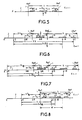
- Figures 14 to 16 show the realization of transition zones using emitting cells to three electrodes per wavelength.
- e defines the sign of the difference ⁇ / 4 walk of the waves reflected on a reflector and depends on the physical properties of the materials composing the filter.
- Phase references transducers 3 and 5 and reflectors 4 and 6 are identified respectively by the letters E and R.
- This cell of length ⁇ has an electrode reflector 7 of width ⁇ / 4 in its center and two electrodes 8 and 9 of width ⁇ / 8 whose centers are distant 3 ⁇ / 8 from the center of the reflective electrode 7 and of which the right electrode 8 is connected to the hot spot.
- the hot spot electrode 8 emits the waves in the preferred direction X in phase opposition with respect to to transducers of type emitting cells known, its center being distant from k ⁇ + ⁇ / 2 from a center transduction E.
- the left electrode 9 cancels the reflection on electrode 8 and, on the other hand, participates in the source in the case where an electrode is attached to the cell hot.
- the cell is thus called -R -E, to be compared to the name E R of the EWC cell shown in the figure 1 and is said to have a negative reflection because the waves reflected by the reflector of this cell are in opposition phase with respect to the waves emitted or reflected by positive reflection cells of the prior art in the preferred direction X of propagation of wave.
- Figure 5 also shows a reflection cell negative called -R since not having transducer and can be used whatever the type of material making up the filter.
- the reflection electrode 7 of width ⁇ / 4 is placed in the center of the cell, the 2 electrodes 8 and 9 of width ⁇ / 8 whose centers are 3 ⁇ / 8 distant from the center of the cell participate at the sources, in the case where the hot electrodes are attached to the cell, compensate for their reflection and keep a metallization ratio roughly constant neighbor for example of 1/2.
- the interposition of a cell of length ⁇ / 2 in downstream of cells of length ⁇ allows, while retaining its reflective characteristics, to reverse the sign of transduction of these cells as explained below.
- width ⁇ / 2 which may include a reflective electrode in its center downstream of the cell of type -R -E thus gives a new cell with negative reflection of type -R E.
- a second cell elementary of width ⁇ / 2 should be placed upstream, always considering the preferred direction of travel waves, if you want to restore the phases of transducers of the emitting cells placed in upstream.
- the elementary cell of width ⁇ / 2 which may include an electrode reflector 10 in its center, placed downstream of the cell E -R shown in Figure 4, transforms this cell into a cell of type -E -R.
- a variant to the cells previously described consists in replacing the width reflectors by ⁇ / 4 of the reflectors of width 3 ⁇ / 8.
- This width of electrode allows when the metallization thickness is sufficient important (h / ⁇ ⁇ 1.5% where h is the metallization thickness and ⁇ the wavelength at the center frequency) to obtain a magnitude of reflection coefficient more important than an electrode of width ⁇ / 4.
- This cell differs from those previously described in that the central electrode 7 has a width of 3 ⁇ / 8 and is connected to the hot spot. It is flanked by 2 electrodes 8 and 9 of width ⁇ / 8, their centers being distant 3 ⁇ / 8 from the center of the cell, the left electrode 9 also being connected to the hot spot.
- the set of two electrodes 7 and 9 connected to the hot spot behaves approximately electrically as a single electrode of width 5 ⁇ / 8.
- the transduction center of this single electrode is in its center. This position corresponds to that of the sources type E.
- the efficiency of the source is proportional to where W is the distance between the centers of the inter electrode spaces.
- W 3 ⁇ / 4 for downstream cells according to the invention, hypothesis in FIG. 8.
- the source efficiency for the E-R cell is therefore, at first order, the same as that of the others sources.
- the negative reflection cell is of the -R -E type.
- An electrode offset of ⁇ / 48 can advantageously be used whenever the hot electrode a cell as described above is surrounded of two non-equal spaces, which is generally the case when using reflectors of width ⁇ / 4.
- the filters according to the invention use transducers DART type comprising, for at least one of them, at least one negative reflection cell.
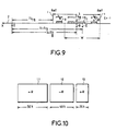
- Figure 10 is an example of realization of a DART used in a filter according to the invention.
- Figure 11 shows the evolution of the reflection coefficient DART as shown in Figure 10 along of the wave propagation axis.
- the abscissa axis represents the propagation axis wave in the DART; he graduated in hundreds wavelength.
- the ordinate axis corresponds to the reflection coefficient of the waves and is graduated in hundredths. The change of sign of this coefficient a place around 50 ⁇ and 90 ⁇ : zone transitions.
- the curves of Figures 12 and 13 give respectively the plots obtained by simulation of the function of transfer of a filter of useful length 15 mm and without negative reflection cells and a length filter useful 11 mm with negative reflection cells.
- Filter attenuation plotted on the ordinate axis in decibels is given as a function of frequency of the signal expressed in megahertz on the abscissa axis.
- the central operating frequency of the filters is 71 MHz.
- Improvements in technical characteristics relate mainly to insertion losses which go from 7.4 dB for the filter according to the prior art to 6.5 dB for the filter according to the invention (not shown on the figures), the variation of the propagation time of group which goes from 200 ns to 100 ns for the filter according to the invention, the decrease in the level of the side lobes and increasing bandwidth.
- E cells and R to constitute the transitions of zones such as shown in Figures 14, 15, 16 and 17 which correspond to the four possible cases.
Landscapes
- Physics & Mathematics (AREA)
- Acoustics & Sound (AREA)
- Surface Acoustic Wave Elements And Circuit Networks Thereof (AREA)
- Radar Systems Or Details Thereof (AREA)
Claims (7)
- Oberflächenwellenwandler mit verteilter akustischer Reflektion des DART-Typs mit einer Nebeneinandersetzung von emittierenden Zellen und reflektierenden Zellen, dadurch gekennzeichnet, dass er folgendes umfasst:wobei jede dieser Zellen zumindest eine Quelle (E) und einen Reflektor (R) umfasst, so dass die von einer Quelle (E) in eine bevorzugte Richtung X emittierten Wellen und die durch einen Reflektor (R) in die Richtung reflektierten Wellen bei der Betriebsmittenfrequenz des Wandlers in Phase sind,zumindest einen Vorzeichenwechsel der Reflektionsfunktion, das heißt er umfasst zumindest einen Reflektor, dessen Mitte um kλ/2 + λ/4 von der Mitte der anderen Reflektoren beabstandet ist, wodurch eine Zelle mit negativer Reflektion (-R) definiert wird, wobei λ die der Betriebsmittenfrequenz des Wandlers entsprechende Wellenlänge und k eine von Null verschiedene ganz Zahl ist,Bereiche (11, 13) von Zellen mit positiver Reflektion, die mit E, R bezeichnet sind,wobei die angepasste räumliche Verteilung der Zellen mit positiver Reflektion und der Zellen mit negativer Reflektion es gestattet, das Äquivalent von kleinen Resonanzhohlräumen im Inneren ein und desselben DART zu erzeugen.Bereiche (12) von Zellen mit negativer Reflektion, die Reflektionszellen (-R) umfassen, wie sie oben definiert sind, und in denen die reflektierten Wellen relativ zu den durch die Zellen mit positiver Reflektion emittierten oder reflektierten Wellen in der bevorzugten Richtung X und bei der Betriebsmittenfrequenz des Wandlers gegenphasig sind,
- Wandler nach Anspruch 1, dadurch gekennzeichnet, daß eine oder mehrere Zellen mit negativer Reflexion (7, 8, 9) von der Länge der der Betriebsmittenfrequenz des Wandlers entsprechenden Wellenlänge λ eine in ihrer Mitte angeordnete Reflexionselektrode (7) besetzen, deren Breite gleich einem Viertel der Wellenlänge λ ist.
- Wandler nach Anspruch 1, dadurch gekennzeichnet, daß eine oder mehrere Zellen mit negativer Reflexion (7, 8, 9) von der Länge der der Betriebsmittenfrequenz des Wandlers entsprechenden Wellenlänge λ eine in ihrer Mitte angeordnete Reflexionselektrode (7) besitzen, deren Breite gleich drei Achteln der Wellenlänge λ ist.
- Wandler nach Anspruch 1, dadurch gekennzeichnet, daß wenigstens eine Zelle mit negativer Reflexion (7, 8, 9) von der Länge der der Betriebsmittenfrequenz des Wandlers entsprechenden Wellenlänge λ durch eine zentrale Elektrode (7) mit einer Breite von drei Achteln der Wellenlänge λ gebildet ist, die mit dem heißen Punkt verbunden ist und von zwei Elektroden (8, 9) mit der Breite eines Achtels der Wellenlänge λ flankiert ist, deren Mitte von der Mitte der Zelle (7, 8, 9) einen Abstand von drei Achteln der Wellenlänge hat, und wovon eine der beiden Zellen (8, 9) ebenfalls mit dem heißen Punkt verbunden ist.
- Wandler nach Anspruch 1 , dadurch gekennzeichnet, daß er, betrachtet in der Ausbreitungsrichtung X der im DART resultierenden Welle, vor wenigstens einer Zelle mit negativer Reflexion (7, 8, 9) eine Elementarzelle (10) von der Länge der Hälfte der der Betriebsmittenfrequenz des Wandlers entsprechenden Wellenlänge λ aufweist, die in ihrer Mitte eine Reflexionselektrode (10) der Breite haben kann.
- Wandler nach den Ansprüchen 1 bis 5, dadurch gekennzeichnet, daß er Sendezellen von der Länge der Wellenlänge λ enthält, die drei Elektroden der Breite λ/6 im Abstand X/3 aufweisen, sowie Reflektorzellen von der Länge der Wellenlänge λ, die zwei Elektroden der Breite λ/4 im Abstand X/2 aufweisen, und daß zwei Reflektorzellen oder zwei Sendezellen den Abstand λ/3 oder 2λ/3 haben.
- Oberflächenwellenfilter, dadurch gekennzeichnet, daß es wenigstens einen Wandler nach einem der Ansprüche 1 bis 6 enthält.
Applications Claiming Priority (3)
| Application Number | Priority Date | Filing Date | Title |
|---|---|---|---|
| FR9303205A FR2702899B1 (fr) | 1993-03-19 | 1993-03-19 | Transducteur à ondes de surface à réflexion acoustique distribuée et filtre comportant un tel transducteur. |
| FR9303205 | 1993-03-19 | ||
| PCT/FR1994/000240 WO1994022217A1 (fr) | 1993-03-19 | 1994-03-04 | Transducteur a ondes de surface a reflexion acoustique distribuee et filtre comportant un tel transducteur |
Publications (3)
| Publication Number | Publication Date |
|---|---|
| EP0646296A1 EP0646296A1 (de) | 1995-04-05 |
| EP0646296B1 EP0646296B1 (de) | 1997-01-22 |
| EP0646296B2 true EP0646296B2 (de) | 2004-06-16 |
Family
ID=9445165
Family Applications (1)
| Application Number | Title | Priority Date | Filing Date |
|---|---|---|---|
| EP94909149A Expired - Lifetime EP0646296B2 (de) | 1993-03-19 | 1994-03-04 | Wandler für Oberflächenwellen mit verteilter akustischer Reflektion und Filter mit solch einem Wandler |
Country Status (5)
| Country | Link |
|---|---|
| EP (1) | EP0646296B2 (de) |
| DE (1) | DE69401557T3 (de) |
| DK (1) | DK0646296T3 (de) |
| FR (1) | FR2702899B1 (de) |
| WO (1) | WO1994022217A1 (de) |
Families Citing this family (1)
| Publication number | Priority date | Publication date | Assignee | Title |
|---|---|---|---|---|
| US6147574A (en) * | 1997-11-20 | 2000-11-14 | Murata Manufacturing Co., Ltd. | Unidirectional surface acoustic wave transducer and transversal-type saw filter having the same |
Citations (1)
| Publication number | Priority date | Publication date | Assignee | Title |
|---|---|---|---|---|
| EP0140618A2 (de) † | 1983-10-14 | 1985-05-08 | The Secretary of State for Defence in Her Britannic Majesty's Government of the United Kingdom of Great Britain and | Akustischer Wandler |
Family Cites Families (2)
| Publication number | Priority date | Publication date | Assignee | Title |
|---|---|---|---|---|
| JPH03119815A (ja) * | 1989-10-01 | 1991-05-22 | Kazuhiko Yamanouchi | 浮き電極をもつ内部反射型一方向性弾性表面波変換器 |
| FR2653632B1 (fr) * | 1989-10-20 | 1991-12-20 | Thomson Csf | Transducteur d'ondes de surface unidirectionnel. |
-
1993
- 1993-03-19 FR FR9303205A patent/FR2702899B1/fr not_active Expired - Lifetime
-
1994
- 1994-03-04 WO PCT/FR1994/000240 patent/WO1994022217A1/fr not_active Ceased
- 1994-03-04 DK DK94909149T patent/DK0646296T3/da active
- 1994-03-04 DE DE69401557T patent/DE69401557T3/de not_active Expired - Lifetime
- 1994-03-04 EP EP94909149A patent/EP0646296B2/de not_active Expired - Lifetime
Patent Citations (1)
| Publication number | Priority date | Publication date | Assignee | Title |
|---|---|---|---|---|
| EP0140618A2 (de) † | 1983-10-14 | 1985-05-08 | The Secretary of State for Defence in Her Britannic Majesty's Government of the United Kingdom of Great Britain and | Akustischer Wandler |
Non-Patent Citations (5)
| Title |
|---|
| C. Scholl et al., "New Resonator Filter with high Sidelobe Suppression", Proc. of the Ultrasonics Symposium 1992, pages 117-121; † |
| C.S. Hartmann, B.P. Abbott, "Overview of Design Challenges for Single-phase unidirectional SAW Filters", Proc. of the Ultrasonics Symposium 1989, pages 79-88; † |
| P. Ventura et al.; Synthesis of SPUDT Filters with simultaneous Reflection and Transduction Optimization", Proc. of the Ultrasonics Symposium 1992, pages 71-75. † |
| P.V. Wright, S.A. Wilkus, "A Prototype low-loss Filter employing Single-phase unidirectional Transducers", Proc. of the Ultrasonics Symposium 1983, pages 72-75; † |
| T. Kodama et al.,"Design of low-los SAW filters employing distributed acoustic reflection transducers", 1986 IEEE Ultrasonics Symposium Proceedings, pages 59-64 † |
Also Published As
| Publication number | Publication date |
|---|---|
| WO1994022217A1 (fr) | 1994-09-29 |
| DE69401557T3 (de) | 2005-02-03 |
| FR2702899B1 (fr) | 1995-05-12 |
| DE69401557D1 (de) | 1997-03-06 |
| EP0646296B1 (de) | 1997-01-22 |
| EP0646296A1 (de) | 1995-04-05 |
| DE69401557T2 (de) | 1997-05-15 |
| DK0646296T3 (da) | 1997-07-28 |
| FR2702899A1 (fr) | 1994-09-23 |
Similar Documents
| Publication | Publication Date | Title |
|---|---|---|
| CA2121477C (fr) | Filtre a ondes de surface et a trajet acoustique replie | |
| EP2203976B1 (de) | Lambwellenresonator | |
| EP1053593B1 (de) | Resonatorfilter mit akustischen oberflächenwellen | |
| FR2601824A1 (fr) | Filtre d'onde elastique de surface | |
| FR3115428A1 (fr) | Dispositif électromécanique à fréquence de résonance ajustable | |
| EP2385625A1 (de) | Kombinierer mit akustischem Wandler | |
| EP0513085A1 (de) | Akustische oberflächenwellenfilter. | |
| EP0660981B1 (de) | Wandler für unidirektionale Weller | |
| FR2776863A1 (fr) | Composant acoustique a ondes de surface | |
| FR3079101A1 (fr) | Structure de transducteur pour suppression de source dans les dispositifs de filtres a ondes acoustiques de surface | |
| EP0646296B1 (de) | Wandler für Oberflächenwellen mit verteilter akustischer Reflektion und Filter mit solch einem Wandler | |
| EP0862813B1 (de) | Differenzbetriebener wandler für akustische oberflächenwellen | |
| EP1082812B1 (de) | Engspaltiger akustischer oberflächenwellenwandler | |
| EP0424240B1 (de) | Richtwandler für Oberflächenwellen | |
| EP3032742A2 (de) | Elastische oberflächenwellen verwendende sensorvorrichtung geeignet zur fernabfrage | |
| EP2324516B1 (de) | Akustisches grenzflächenwellenelement | |
| WO1995014332A1 (fr) | Filtre a ondes de surface a trajet acoustique replie | |
| FR2596593A1 (fr) | Procede de suppression des echos parasites dans les lignes a retard electroacoustiques a ondes de volume, et ligne a retard mettant en oeuvre ce procede | |
| FR2818051A1 (fr) | Flitres a ondes acoustiques de surface a symetrie optimisee | |
| FR3162108A1 (fr) | Dispositif à ondes élastiques | |
| EP0576340B1 (de) | Oberflächenwellenfilter mit reflektierenden Gittern | |
| FR2476360A1 (de) | ||
| FR2848745A1 (fr) | Filtre dms a faibles pertes d'insertion et symetrie optimisee |
Legal Events
| Date | Code | Title | Description |
|---|---|---|---|
| PUAI | Public reference made under article 153(3) epc to a published international application that has entered the european phase |
Free format text: ORIGINAL CODE: 0009012 |
|
| 17P | Request for examination filed |
Effective date: 19941110 |
|
| AK | Designated contracting states |
Kind code of ref document: A1 Designated state(s): CH DE DK GB LI SE |
|
| GRAG | Despatch of communication of intention to grant |
Free format text: ORIGINAL CODE: EPIDOS AGRA |
|
| 17Q | First examination report despatched |
Effective date: 19960304 |
|
| GRAH | Despatch of communication of intention to grant a patent |
Free format text: ORIGINAL CODE: EPIDOS IGRA |
|
| GRAH | Despatch of communication of intention to grant a patent |
Free format text: ORIGINAL CODE: EPIDOS IGRA |
|
| GRAA | (expected) grant |
Free format text: ORIGINAL CODE: 0009210 |
|
| AK | Designated contracting states |
Kind code of ref document: B1 Designated state(s): CH DE DK GB LI SE |
|
| REG | Reference to a national code |
Ref country code: CH Ref legal event code: EP |
|
| REF | Corresponds to: |
Ref document number: 69401557 Country of ref document: DE Date of ref document: 19970306 |
|
| GBT | Gb: translation of ep patent filed (gb section 77(6)(a)/1977) |
Effective date: 19970402 |
|
| REG | Reference to a national code |
Ref country code: DK Ref legal event code: T3 |
|
| PLBI | Opposition filed |
Free format text: ORIGINAL CODE: 0009260 |
|
| 26 | Opposition filed |
Opponent name: SIEMENS AG Effective date: 19971022 |
|
| PLBF | Reply of patent proprietor to notice(s) of opposition |
Free format text: ORIGINAL CODE: EPIDOS OBSO |
|
| PGFP | Annual fee paid to national office [announced via postgrant information from national office to epo] |
Ref country code: CH Payment date: 19980211 Year of fee payment: 5 |
|
| PLBF | Reply of patent proprietor to notice(s) of opposition |
Free format text: ORIGINAL CODE: EPIDOS OBSO |
|
| PGFP | Annual fee paid to national office [announced via postgrant information from national office to epo] |
Ref country code: DK Payment date: 19980324 Year of fee payment: 5 |
|
| PLBF | Reply of patent proprietor to notice(s) of opposition |
Free format text: ORIGINAL CODE: EPIDOS OBSO |
|
| PG25 | Lapsed in a contracting state [announced via postgrant information from national office to epo] |
Ref country code: LI Free format text: LAPSE BECAUSE OF NON-PAYMENT OF DUE FEES Effective date: 19990331 Ref country code: DK Free format text: LAPSE BECAUSE OF NON-PAYMENT OF DUE FEES Effective date: 19990331 Ref country code: CH Free format text: LAPSE BECAUSE OF NON-PAYMENT OF DUE FEES Effective date: 19990331 |
|
| REG | Reference to a national code |
Ref country code: CH Ref legal event code: PL |
|
| REG | Reference to a national code |
Ref country code: DK Ref legal event code: EBP |
|
| PLAW | Interlocutory decision in opposition |
Free format text: ORIGINAL CODE: EPIDOS IDOP |
|
| APAC | Appeal dossier modified |
Free format text: ORIGINAL CODE: EPIDOS NOAPO |
|
| APAE | Appeal reference modified |
Free format text: ORIGINAL CODE: EPIDOS REFNO |
|
| PLBQ | Unpublished change to opponent data |
Free format text: ORIGINAL CODE: EPIDOS OPPO |
|
| PLAB | Opposition data, opponent's data or that of the opponent's representative modified |
Free format text: ORIGINAL CODE: 0009299OPPO |
|
| APAC | Appeal dossier modified |
Free format text: ORIGINAL CODE: EPIDOS NOAPO |
|
| R26 | Opposition filed (corrected) |
Opponent name: SIEMENS AG Effective date: 19971022 |
|
| RAP2 | Party data changed (patent owner data changed or rights of a patent transferred) |
Owner name: THALES |
|
| REG | Reference to a national code |
Ref country code: GB Ref legal event code: IF02 |
|
| APBU | Appeal procedure closed |
Free format text: ORIGINAL CODE: EPIDOSNNOA9O |
|
| PUAH | Patent maintained in amended form |
Free format text: ORIGINAL CODE: 0009272 |
|
| STAA | Information on the status of an ep patent application or granted ep patent |
Free format text: STATUS: PATENT MAINTAINED AS AMENDED |
|
| 27A | Patent maintained in amended form |
Effective date: 20040616 |
|
| AK | Designated contracting states |
Kind code of ref document: B2 Designated state(s): CH DE DK GB LI SE |
|
| REG | Reference to a national code |
Ref country code: SE Ref legal event code: RPEO |
|
| GBTA | Gb: translation of amended ep patent filed (gb section 77(6)(b)/1977) | ||
| APAH | Appeal reference modified |
Free format text: ORIGINAL CODE: EPIDOSCREFNO |
|
| REG | Reference to a national code |
Ref country code: GB Ref legal event code: 732E |
|
| REG | Reference to a national code |
Ref country code: GB Ref legal event code: 732E Free format text: REGISTERED BETWEEN 20090611 AND 20090617 |
|
| PGFP | Annual fee paid to national office [announced via postgrant information from national office to epo] |
Ref country code: SE Payment date: 20090327 Year of fee payment: 16 |
|
| EUG | Se: european patent has lapsed | ||
| PG25 | Lapsed in a contracting state [announced via postgrant information from national office to epo] |
Ref country code: SE Free format text: LAPSE BECAUSE OF NON-PAYMENT OF DUE FEES Effective date: 20100305 |
|
| PGFP | Annual fee paid to national office [announced via postgrant information from national office to epo] |
Ref country code: GB Payment date: 20130327 Year of fee payment: 20 Ref country code: DE Payment date: 20130321 Year of fee payment: 20 |
|
| REG | Reference to a national code |
Ref country code: DE Ref legal event code: R071 Ref document number: 69401557 Country of ref document: DE |
|
| REG | Reference to a national code |
Ref country code: GB Ref legal event code: PE20 Expiry date: 20140303 |
|
| PG25 | Lapsed in a contracting state [announced via postgrant information from national office to epo] |
Ref country code: GB Free format text: LAPSE BECAUSE OF EXPIRATION OF PROTECTION Effective date: 20140303 Ref country code: DE Free format text: LAPSE BECAUSE OF EXPIRATION OF PROTECTION Effective date: 20140305 |