EP0645741A2 - Cash-desk with two cashiers, operating at both sides - Google Patents
Cash-desk with two cashiers, operating at both sides Download PDFInfo
- Publication number
- EP0645741A2 EP0645741A2 EP94111368A EP94111368A EP0645741A2 EP 0645741 A2 EP0645741 A2 EP 0645741A2 EP 94111368 A EP94111368 A EP 94111368A EP 94111368 A EP94111368 A EP 94111368A EP 0645741 A2 EP0645741 A2 EP 0645741A2
- Authority
- EP
- European Patent Office
- Prior art keywords
- unit
- safe
- cash
- banknote
- punched
- Prior art date
- Legal status (The legal status is an assumption and is not a legal conclusion. Google has not performed a legal analysis and makes no representation as to the accuracy of the status listed.)
- Granted
Links
- 230000008878 coupling Effects 0.000 claims description 8
- 238000010168 coupling process Methods 0.000 claims description 8
- 238000005859 coupling reaction Methods 0.000 claims description 8
- 238000013461 design Methods 0.000 claims description 4
- 238000003780 insertion Methods 0.000 claims description 3
- 230000037431 insertion Effects 0.000 claims description 3
- 230000004888 barrier function Effects 0.000 claims 1
- 230000005540 biological transmission Effects 0.000 claims 1
- 239000004020 conductor Substances 0.000 claims 1
- 238000005192 partition Methods 0.000 claims 1
- 238000000638 solvent extraction Methods 0.000 abstract 1
- 125000006850 spacer group Chemical group 0.000 description 5
- 239000000463 material Substances 0.000 description 4
- 230000000712 assembly Effects 0.000 description 3
- 238000000429 assembly Methods 0.000 description 3
- 238000004080 punching Methods 0.000 description 3
- 230000007547 defect Effects 0.000 description 2
- 230000002950 deficient Effects 0.000 description 2
- 238000000926 separation method Methods 0.000 description 2
- 238000012360 testing method Methods 0.000 description 2
- 229940112822 chewing gum Drugs 0.000 description 1
- 235000015218 chewing gum Nutrition 0.000 description 1
- 238000005253 cladding Methods 0.000 description 1
- 238000010276 construction Methods 0.000 description 1
- 238000013479 data entry Methods 0.000 description 1
- 239000013013 elastic material Substances 0.000 description 1
- 239000002184 metal Substances 0.000 description 1
- 238000012546 transfer Methods 0.000 description 1
- 230000007704 transition Effects 0.000 description 1
Images


Classifications
-
- E—FIXED CONSTRUCTIONS
- E05—LOCKS; KEYS; WINDOW OR DOOR FITTINGS; SAFES
- E05G—SAFES OR STRONG-ROOMS FOR VALUABLES; BANK PROTECTION DEVICES; SAFETY TRANSACTION PARTITIONS
- E05G5/00—Bank protection devices
- E05G5/006—Cashier's counters or receptables for holding valuables readily accessible for handling, with safeguard mechanisms for the valuables in case of hold-up
-
- B—PERFORMING OPERATIONS; TRANSPORTING
- B65—CONVEYING; PACKING; STORING; HANDLING THIN OR FILAMENTARY MATERIAL
- B65H—HANDLING THIN OR FILAMENTARY MATERIAL, e.g. SHEETS, WEBS, CABLES
- B65H29/00—Delivering or advancing articles from machines; Advancing articles to or into piles
- B65H29/58—Article switches or diverters
-
- E—FIXED CONSTRUCTIONS
- E05—LOCKS; KEYS; WINDOW OR DOOR FITTINGS; SAFES
- E05G—SAFES OR STRONG-ROOMS FOR VALUABLES; BANK PROTECTION DEVICES; SAFETY TRANSACTION PARTITIONS
- E05G1/00—Safes or strong-rooms for valuables
- E05G1/005—Portable strong boxes, e.g. which may be fixed to a wall or the like
-
- F—MECHANICAL ENGINEERING; LIGHTING; HEATING; WEAPONS; BLASTING
- F16—ENGINEERING ELEMENTS AND UNITS; GENERAL MEASURES FOR PRODUCING AND MAINTAINING EFFECTIVE FUNCTIONING OF MACHINES OR INSTALLATIONS; THERMAL INSULATION IN GENERAL
- F16B—DEVICES FOR FASTENING OR SECURING CONSTRUCTIONAL ELEMENTS OR MACHINE PARTS TOGETHER, e.g. NAILS, BOLTS, CIRCLIPS, CLAMPS, CLIPS OR WEDGES; JOINTS OR JOINTING
- F16B5/00—Joining sheets or plates, e.g. panels, to one another or to strips or bars parallel to them
- F16B5/02—Joining sheets or plates, e.g. panels, to one another or to strips or bars parallel to them by means of fastening members using screw-thread
- F16B5/0291—Joining sheets or plates, e.g. panels, to one another or to strips or bars parallel to them by means of fastening members using screw-thread the threaded element being driven through the edge of a sheet plate with its axis in the plane of the plate
-
- G—PHYSICS
- G07—CHECKING-DEVICES
- G07D—HANDLING OF COINS OR VALUABLE PAPERS, e.g. TESTING, SORTING BY DENOMINATIONS, COUNTING, DISPENSING, CHANGING OR DEPOSITING
- G07D11/00—Devices accepting coins; Devices accepting, dispensing, sorting or counting valuable papers
- G07D11/10—Mechanical details
- G07D11/14—Inlet or outlet ports
-
- G—PHYSICS
- G07—CHECKING-DEVICES
- G07D—HANDLING OF COINS OR VALUABLE PAPERS, e.g. TESTING, SORTING BY DENOMINATIONS, COUNTING, DISPENSING, CHANGING OR DEPOSITING
- G07D11/00—Devices accepting coins; Devices accepting, dispensing, sorting or counting valuable papers
- G07D11/10—Mechanical details
- G07D11/16—Handling of valuable papers
- G07D11/18—Diverting into different paths or containers
-
- G—PHYSICS
- G07—CHECKING-DEVICES
- G07D—HANDLING OF COINS OR VALUABLE PAPERS, e.g. TESTING, SORTING BY DENOMINATIONS, COUNTING, DISPENSING, CHANGING OR DEPOSITING
- G07D11/00—Devices accepting coins; Devices accepting, dispensing, sorting or counting valuable papers
- G07D11/40—Device architecture, e.g. modular construction
-
- B—PERFORMING OPERATIONS; TRANSPORTING
- B65—CONVEYING; PACKING; STORING; HANDLING THIN OR FILAMENTARY MATERIAL
- B65H—HANDLING THIN OR FILAMENTARY MATERIAL, e.g. SHEETS, WEBS, CABLES
- B65H2404/00—Parts for transporting or guiding the handled material
- B65H2404/60—Other elements in face contact with handled material
- B65H2404/61—Longitudinally-extending strips, tubes, plates, or wires
- B65H2404/611—Longitudinally-extending strips, tubes, plates, or wires arranged to form a channel
- B65H2404/6111—Longitudinally-extending strips, tubes, plates, or wires arranged to form a channel and shaped for curvilinear transport path
-
- B—PERFORMING OPERATIONS; TRANSPORTING
- B65—CONVEYING; PACKING; STORING; HANDLING THIN OR FILAMENTARY MATERIAL
- B65H—HANDLING THIN OR FILAMENTARY MATERIAL, e.g. SHEETS, WEBS, CABLES
- B65H2404/00—Parts for transporting or guiding the handled material
- B65H2404/60—Other elements in face contact with handled material
- B65H2404/61—Longitudinally-extending strips, tubes, plates, or wires
- B65H2404/611—Longitudinally-extending strips, tubes, plates, or wires arranged to form a channel
- B65H2404/6112—Longitudinally-extending strips, tubes, plates, or wires arranged to form a channel and displaceable for changing direction of transport
-
- E—FIXED CONSTRUCTIONS
- E05—LOCKS; KEYS; WINDOW OR DOOR FITTINGS; SAFES
- E05G—SAFES OR STRONG-ROOMS FOR VALUABLES; BANK PROTECTION DEVICES; SAFETY TRANSACTION PARTITIONS
- E05G7/00—Safety transaction partitions, e.g. movable pay-plates; Bank drive-up windows
- E05G7/001—Bank depositories
Definitions
- the invention relates to a cash vault according to the preamble of patent claim 1, a connection according to the preamble of patent claim 8 and a fastening means for cable bundles according to patent claim 14.
- Cash safes are set up in the counter halls of banking institutions. They are devices in which money can be stored with great security precautions and from which bank employees or bank customers can retrieve an amount of money for spending after prior identification and often by entering security codes.
- the cash safes are designed in such a way that only a very small amount can be captured in the event of a bank robbery. Even a bank robber cannot access the amount of money stored in the money store within a "useful" period.
- the cash vault described below is designed in such a way that it can serve two cashiers (bank employees).
- the invention solves the problem of creating a cash vault which is characterized by a particular ease of servicing and in which the service work on the banknote input / output unit, which in itself is rare, can already be carried out in the counter hall while ensuring against unauthorized access to the amount of money stored in the money store .
- the cash vault Due to its armor, the space for the banknotes to be stored and the assemblies necessary for operation, the cash vault has a predetermined minimum volume.
- the banknote input / output unit was constructed in such a way that all the assemblies required for the banknote input and output were concentrated in a single sub-area.
- a shapely designed cover of the banknote input / output unit is now formed in two parts, one part covering the above assemblies and the other part continuing only the cover form of the first cover.
- the cash vault can thus be set up on its own or partially used under the bench counter, in which case the second cover part (cladding part) has been removed.
- the arrangement of the banknote storage unit has been carried out in the basic safe unit such that it can be pulled out.
- the banknote storage unit in the basic safe unit is moved on guide elements, in particular on rails.
- the lock is designed in the base unit of the safe in such a way that when the banknote storage unit is unlocked, the banknote storage unit is automatically switched off and the electrical contacts are automatically decoupled when it is pulled out.
- the plug connections therefore no longer have to be released or closed separately by hand by coupling or uncoupling the plug connections. A tearing out of cable connections is therefore excluded when the storage unit is pulled out of the basic safe unit.
- the easy accessibility is achieved in particular by a connection which is easy to produce and which can be used with all sheets which are to be fastened perpendicular to one another.
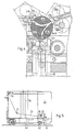
- the 1 shows a cash vault 1 to be used as a cashier by two bank employees 4a and 4b .
- the cash vault 1 is separated from the bank customers by a counter 3 .
- the two bank employees 4a and 4b stand to the right and left of the cash vault 1 .
- Each of the two bank employees 4a and 4b has a terminal 5a and 5b for the data-electronic operation of the cash vault 1 , for the execution of debits, banknote entry and exit, etc.
- the cash vault 1 has a removable banknote input / output unit 10 for service purposes, which together with a covering part 9 forms the upper part of the cash vault 1 .
- a covering part 9 forms the upper part of the cash vault 1 .
- the cash vault 1 can be partially pushed under the counter 3 , in which case the covering part 9 , which contains no functional elements, is removed.
- An output unit 11 and an input unit 39 for banknotes 12 are arranged on the top of the banknote input / output unit 10 .
- the dispensing unit 11 can be completely closed with a two-part cover 13a and 13b .
- the right partial cover 13a can be opened and closed independently of the left 13b .
- the right cover 13a is closed and the left partial cover 13b is shown open.
- the bank clerk 4b standing on the left side of the cash vault 1 has free access from above left to the bundle of banknotes 12 provided in the output unit 11 for the output. Since the right partial cover 13a of the dispensing unit 11 is closed, the bank clerk 4a standing on the right side of the cash vault 1 has no access into the dispensing unit 11 .
- the dispensing unit 11 is designed as a horizontally transverse trapezoidal longitudinal opening with open end faces on top of the banknote input / output unit 10 .
- the cover of the banknote input / output unit 10 and the trim part 9 extends just above the upper edge of a basic safe unit 15 .
- a cash storage unit, indicated in FIG. 3, is arranged in the basic safe unit 15 as a banknote store 35 .
- the banknote input / output unit 10 is detachably held on the basic safe unit 15 by means of a holding unit 17 shown in FIG .
- the free distance of the holding unit 17 from an upper wall 23 of the safe base unit 15 depends on the thickness of this wall 23 . This thickness can vary depending on the security requirements of the bank. Due to these different thicknesses, the distance of the holding unit 17 from the inside of the wall 23 or from a reference plate 24 arranged at a well-defined distance from the inside must be when mounting the cash vault 1 can be set exactly so that a perfect banknote transfer can take place from the banknote store 35 to the banknote input / output unit 10 .
- To adjust the height of the holding unit 17 four cylindrical mounting bolts 19 (only two are visible in FIG.
- the mounting bolts 19 have a widened upper part 20 . With their thin cross section, they are first inserted through a through hole 18a in the wall 23 and a through hole 18b in the reference plate 24 . The mounting bolts 19 now rest on their transition from the thin cross section to the thicker upper part 20 on the edge of the borehole of the reference plate 24 . A spacer sleeve 26 is now placed over each upper part 20 . The height of the spacer sleeve 26 is a measure of the distance of the holding unit 17 from the safe wall 23, ie from the reference plate 24 .
- Threaded bolts (not shown) are arranged on the wall 23 at the points designated by the reference number 25 . A total of four threaded bolts are used. A first nut, also not shown, is now screwed onto this threaded bolt. Now the holding unit 17 is placed on the mounting bolts 19 . It now rests on the upper end face of the spacer sleeves 26 . The first nuts on the threaded bolts at the point with the reference number 25 are screwed up from the side of the cash vault 1 with a socket wrench until the bottom of the holding unit 17 just lies on them without lifting off the upper end face of the spacer sleeves 26 .
- the holding unit 17 is then removed again, the mounting bolts 19 with the spacer sleeve 26 attached are removed and the holding unit 17 is again placed on the first nuts on the threaded bolts at points 25 .
- a second nut shown at points 25 in FIG. 2 is screwed onto the threaded bolts and braced against the first.
- the holding unit 17 is now mounted in the correct horizontal and vertical position with respect to the basic safe unit 15 .
- the correct horizontal position results from the position of for Threaded bolts in the bottom of the holding unit 17 certain through holes (not shown).
- the position of the plug-on banknote input / output unit 10 relative to the holding unit 17 is determined via three dowel pins 21 , only two of which are shown in FIG .
- the banknote store 35 can also be retracted since they are no longer present in its free space.
- the trim part 9 is clamped to the cover plates of the banknote input / output unit 10 in a manner not shown and can be pulled off upwards.
- the cover plates of the trim part 9 and the banknote input / output unit 10 lie against one another in a joint 27 indicated in FIG .
- FIG. 1 A schematic cross-sectional representation through the entire cash vault 1 is shown in FIG .
- the banknotes are transported upwards from the banknote storage unit 35 arranged in the basic safe unit 15 with a conveyor device 36 to the banknote input / output unit 10 and are stored there by a storage wheel 37 in the output unit 11 to form the bundle 12 .
- Banknotes which are input into an input unit 39 in the banknote input / output unit 10 if they are defective, are transported to the output unit 11 after being checked by a test unit (not shown) or, if they are free of errors, with the conveyor 36 in the banknote memory 35 filed.
- a banknote store of this type with the associated funding is such. B. described in EP-A 0 290 731.
- routing element 41st The routing element 41 is a circular cylinder rotatable about its longitudinal axis 43 with a drive (not shown).
- the circular cylinder is crossed by two axially extending longitudinal slots 45a and 45b .
- the longitudinal slots 45a and 45b cut through the circular cylinder to form three longitudinal cylinder sections 47a , 47b and 47c , which are mechanically held together on the cylinder base and / or head in a manner not shown.
- the two longitudinal slots 45a and 45b are brought together at one point in the cylinder jacket to form a curved V's.
- the ends of the V-legs of the longitudinal slots 45a and 45b are funnel-shaped in cross section in order to ensure a good entry of the banknotes.
- the routing element 41 is in a position in which banknotes, coming from the input unit 39 - indicated by an arrow with the reference number 39 - are guided by the guide rollers 49a and 49b and additionally guided by auxiliary entry elements 51a and 51b into the longitudinal slot 45a are introduced and then leave the latter in the direction of the dispensing unit 11 .
- the delivery unit 11 is guided via funnel-shaped guide plates 53a and 53b and a belt conveyor, only its rollers 55a and 55b being shown.
- the banknotes are transported from the input unit 39 back to the output unit 11 when the banknotes are assessed by a test unit (not shown) as not conforming to the standard. The linear promotion of banknotes will not be discussed further since linear banknote subsidies are known.
- the banknotes are also transported with a belt conveyor device 36 (not described in more detail) through the slot 22 in the upper safe wall of the safe base unit 15 and through the longitudinal slot 45b in the route selection element 41 to the dispensing unit 11 .
- the routing element becomes 41 pivoted such that the funnel-shaped opening of the longitudinal slot 45b can receive banknotes coming from the input unit 39 .
- routing element 41 which is designed compactly as a circular cylinder, lies in its simple design and thus insensitivity to routing elements, which are composed of a multiplicity of deflection plates designed as switches.
- the routing element 41 can be referred to as a "three-way valve" for sheet-like material.
- This route selection element 41 can not only be used in the selection of conveyance routes for banknotes, it can also be used in the case of other sheet-like goods to select different transportation routes. It can be used wherever quick sorting instructions must be followed.
- the speed of the changeover depends only on the moment of inertia of the route selection element, which can be influenced, inter alia, by the choice of the weight (in particular by the choice of the material used) and the cylinder diameter.
- the diameter used depends on the one hand on the rigidity of the material - stiff sheet materials require a larger diameter - and on the other hand on the number of branch points.
- the longitudinal cylinder sections can also be hollow. Only one "skeleton" of the guides 45a and 45b can be used.
- the banknote storage 35 is shown in FIG. 3 and FIG. 6 inside the cash safe 1 and in FIG. 5 in a schematic side view outside the cash safe 1 .
- the banknote store 35 has three wheels 59 , with which it can be moved outside the cash vault 1 on the floor 60 .
- One of the three impellers 59 can be pivoted about a horizontal axis, as indicated in FIG .
- the pivotable impeller is once in the push-out and shown once in the insertion position. There are therefore not two, but only a single front impeller 59 .
- the banknote storage 35 also has two provided with a guide groove 61 of guide wheels 62b and two flat rollers 62a.
- the rollers 62a and the guide wheels 62b run on guide rails 63 in order to be able to push the cash safe 1 precisely onto a “floating” electrical contact coupling 65 .
- the position fixation of the banknote store 35 within the cash vault 1 takes place with a locking pawl 67 which is arranged in a corresponding in the interior of the safe base unit 15 can be engaged counterpart 69th
- On the pawl arm of the locking pawl 67 one end of a cable 73 tensioned via a tension roller 71 is fastened.
- the other end of the cable pull 73 engages on a switching unit 75 biased by a spring 74 for switching the supply voltage which can be fed into the banknote memory 35 via the contact coupling 65 on and off.
- the device If the handle 76 of the locking pawl 67 is pulled upwards when the door 77 of the safe unit 15 is open, the device is switched off and signal lines are disconnected.
- the banknote store 35 can now be extended without the risk of a short circuit when the contact coupling elements of the contact coupling 65 are uncoupled. Interference pulses on the signal lines to be decoupled are also prevented.
- the entry of the banknote storage unit 35 into the electrical contact coupling 65 must take place in the correct position.
- the guide rails 63 on which the rollers 62a and the guide wheels 62b roll, and an inlet pin 79 tapered at its free end serve for this purpose. Since different impellers and guide wheels 59 , 62a and 62b are used in diameter, dirt adhering to the impellers 63 , e.g. B. chewing gum picked up from the bottom 60 , do not cause any guide inaccuracies.
- the cash vault 1 has a plurality of cover plates 83a and 83b , which are not explicitly shown and are perpendicular to one another.
- the cover plates 83a and 83b must be releasably connected to one another.
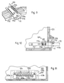
- the connection described below and shown in FIGS. 7 and 8 was developed in order to enable serviceability here, too, by quick detachability and renewed fixing.
- both plates 83a and 83b have no bends as connecting flanges.
- the two sheets 83a and 83b only require punchings 85a and 85b , the punching 85b also being able to be designed as a bore.
- the cutout 85a is composed of two slot-shaped cutouts 87a and 87b which are perpendicular to one another.
- the cutout 87a runs approximately parallel to the contact edge 86 of the sheet 83a on which the sheet 85b rests.
- a holding plate 89 as a holding element can be partially inserted into this punch-out 87a .
- the cutout 87b opens vertically into the cutout 87a and is open toward the support edge 86 , so that a screw 91 which can be inserted through the cutout 85b can engage through this cutout 87b into a threaded hole 93 matching the screw thread as a force-engaging element in the holding plate 89 .
- the punched-out 87b has been continued beyond the punched-out 87a . The screw end can then run into the continuation.
- a clip 94 which holds the holding plate 89 detachably in the punched-out area 87a .
- the clip 94 has two mutually spaced, mutually parallel U-shaped legs 96a to 96d made of elastic material, in particular plastic. The distance between the two legs 96a and 96b and 96c and 96d is a clearance tolerance greater than the thickness of the holding plate 89 .
- the clip 94 has a pull tab 97 on the outside and on the bottom of the U's on the left and right. The ends of the U-legs 96a to 96d carry locking elements 99 .
- the holding plate 89 If the holding plate 89 is inserted into the cutout 85a , it lies in the cutout 87a and the legs 96a to 96d of the clip 94 reach through the cutout 87b and its extension.
- the locking elements 99a to 99d snap into place on the upper side of the sheet 83a .
- To remove the holding plate 89 inserted into the punched-out 87a only the locking elements 99a to 99d are pressed inwards with flat-nose pliers and the clip 94 is pulled out on its pull-out tabs 97 .
- the ends of the pull-out tabs 97 are bent against the locking elements 99 .
- the ends of the pull-out tabs 97 are pressed against the surface of the sheet 83a .
- the locking elements 99 are pulled against the other surface of the sheet 83a , as a result of which the clip 94 and the holding plate 89 are held in their position without play.
- the holding plate 89 is constructed mirror-symmetrically with respect to its longitudinal axis 101 and is narrowed by two shoulders 103 and 105 in the direction of insertion 106 .
- the two shoulders 103 serve as stops on the surface of the sheet 83a so that the holding plate 89 cannot be pushed through the punched-out 87a .
- the shoulders 105 allow the four U-leg ends to be bent against one another with flat-nose pliers when the retaining plate 89 secured with the clip 94 is removed. If the two shoulders 105 causing a reduction in width were not present, the inner surfaces of the jaws would abut the holding plate 89 and the legs 96a to 96d would not be able to bend against one another .
- Punching 87b can be dispensed with if the achievable connecting forces may be low.
- an L-shaped tension element is used instead of the screw 91 .
- the vertical leg of this tension element is then inserted through a punch-out similar to the punch-out 85b , which, however, must be offset by at least half the sheet thickness.
- the L-shaped tension element then has a thread on its vertical leg, onto which a nut is screwed in order to make the connection.
- a through bore with a slot can also be provided, into which a spring-loaded bayonet lock is inserted instead of the screw 91 .
- the cash vault 1 is connected via cables indicated in FIG. 3 to the two terminals 5a and 5b , to a central computer (not shown), alarm devices, the power supply, etc.
- the cables 115 coming out of the cash safe 1 are fastened to the inner wall of the safe base unit 15 with a fastening means 109 for relieving their tension.
- the fastening means 109 shown in FIGS. 9 to 11 has a channel-like holding rail 111 which is bent in a U-shaped cross section.
- the U-shaped groove of the holding rail 111 is covered by a pressure plate 113 .
- This pressure plate 113 presses the cables 115 to be held into recesses 117a and 117b in the legs 119a and 119b .
- the shields 125 are held by the leg 119a and the insulating cable sheaths 131 above the shield 125 by the leg 119b . Slipping of the cable sheath 131 relative to the stripped sheathing point is prevented by pulling on the cable from the outside. Shield 125 can be grounded via leg 119a .
- the leg 119b is elongated with respect to the leg 119a both laterally and in height. In these extended areas, it carries through bores 121a to 121d which, as shown in FIG. 10 , are provided for fastening to the safe wall 123 .
- a rubber-elastic pressure plate 125 is arranged under the pressure plate 113 , which presses on the cable sheaths in the assembled state.
- Both legs 119a and 119b are slit like a comb, as shown in FIG .
- the cables 115 are located in the spaces 117a and 117b .
Landscapes
- General Physics & Mathematics (AREA)
- Physics & Mathematics (AREA)
- Engineering & Computer Science (AREA)
- Mechanical Engineering (AREA)
- General Engineering & Computer Science (AREA)
- Business, Economics & Management (AREA)
- Accounting & Taxation (AREA)
- Finance (AREA)
- Financial Or Insurance-Related Operations Such As Payment And Settlement (AREA)
- Control Of Vending Devices And Auxiliary Devices For Vending Devices (AREA)
- Sheets, Magazines, And Separation Thereof (AREA)
- Cash Registers Or Receiving Machines (AREA)
- Addition Polymer Or Copolymer, Post-Treatments, Or Chemical Modifications (AREA)
- Display Devices Of Pinball Game Machines (AREA)
- Cleaning Implements For Floors, Carpets, Furniture, Walls, And The Like (AREA)
- Pile Receivers (AREA)
Abstract
Description
Die Erfindung betrifft einen Kassentresor gemäß dem Oberbegriff des Patentanspruchs 1, eine Verbindung gemäß dem Oberbegriff des Patentanspruchs 8 und ein Befestigungsmittel für Kabelbündel gemäß dem Patentanspruch 14.The invention relates to a cash vault according to the preamble of
Kassentresore werden in den Schalterhallen von Bankinstituten aufgestellt. Sie sind Geräte, in denen Geld unter großen Sicherheitsvorkehrungen abspeicherbar ist und aus denen Bankangestellte oder auch Bankkunden nach vorheriger Identifikation und oftmals unter Eingabe von Sicherheits-Codes einen Geldbetrag zur Ausgabe abrufen können. Die Kassentresore sind derart ausgebildet, daß bei einem Banküberfall nur ein äußerst geringer Betrag erbeutet werden kann. An die im Geldspeicher eingelagerte Geldmenge kann auch ein Bankräuber nicht innerhalb "nützlicher" Frist heran kommen. Der nachfolgend beschriebene Kassentresor ist derart ausgelegt, daß er zwei Kassierer (Bankangestellte) bedienen kann.Cash safes are set up in the counter halls of banking institutions. They are devices in which money can be stored with great security precautions and from which bank employees or bank customers can retrieve an amount of money for spending after prior identification and often by entering security codes. The cash safes are designed in such a way that only a very small amount can be captured in the event of a bank robbery. Even a bank robber cannot access the amount of money stored in the money store within a "useful" period. The cash vault described below is designed in such a way that it can serve two cashiers (bank employees).
Ausgehend von den geforderten Sicherheitsvorkehrungen sind bekannte Kassentresore derart ausgelegt, daß Manipulationen und sei es auch nur zur Behebung eines kleinen mechanischen Defektes bei Publikumsverkehr, an ihnen nicht ausführbar sind, da bei Servicearbeiten die geforderten Sicherheitsanforderungen betreffend eingelagertem Geldbetrag nicht eingehalten werden konnten.Based on the required safety precautions, well-known cash register safes are designed in such a way that manipulations, even if only to remedy a small mechanical defect in public traffic, cannot be carried out on them, since the required security requirements regarding the amount of money stored could not be met during service work.
Die Erfindung löst die Aufgabe einen Kassentresor zu schaffen, der sich durch eine besondere Servicefreundlichkeit auszeichnet und bei dem die an sich schon seltenen Servicearbeiten an der Banknotenein-/ausgabeeinheit bereits in der Schalterhalle unter Sicherstellung gegen unbefugten Zugriff auf den im Geldspeicher abgespeicherten Geldbetrag vorgenommen werden können.The invention solves the problem of creating a cash vault which is characterized by a particular ease of servicing and in which the service work on the banknote input / output unit, which in itself is rare, can already be carried out in the counter hall while ensuring against unauthorized access to the amount of money stored in the money store .
Durch eine klare konstruktive Trennung der Banknotenein-/ausgabeeinheit von der Tresorgrundeinheit ist es möglich, die nicht den Sicherheitsvorkehrungen unterliegende Vereinzelung und Bündelbildung der Banknoten hier zu vollziehen. Die Banknoten müssen dann nur noch einzeln vom oder in den Banknotenspeicher durch einen Durchbruch in der Wandung der Tresorgrundeinheit transportiert werden. Durch Justierelemente läßt sich die Banknotenein-/ausgabeeinheit zum Durchbruch mit einer ausreichenden Genauigkeit anordnen, wodurch eine einwandfreie Übergabe der Banknoten gewährleistet ist. Durch die gewählte Konstruktion der Justage ist die Banknotenein-/ausgabe von der Tresorgrundeinheit abnehmbar. Sollte nun z. B. ein eventueller Banknotenstau oder ein anderer Defekt sich ergeben, können somit Servicehandlungen ohne Sicherheitsrisiko jederzeit, auch bei Publikumsverkehr in der Schalterhalle, vorgenommen werden.Through a clear constructive separation of the banknote input / output unit from the basic safe unit, it is possible to carry out the separation and bundling of the banknotes which are not subject to the safety precautions here. The banknotes then only have to be transported individually from or into the banknote store through an opening in the wall of the basic safe unit. Adjustment elements allow the banknote input / output unit to be arranged for breakthrough with sufficient accuracy, which ensures that the banknotes are transferred correctly. Due to the selected construction of the adjustment, the banknote input / output can be removed from the safe base unit. Should z. If, for example, a possible banknote jam or other defect occurs, service can be carried out at any time without security risk, even when there is public traffic in the counter hall.
Der Kassentresor weist aufgrund seiner Panzerung, dem Raum für die zu speichernden Banknoten und die für den Betrieb notwendigen Baugruppen ein vorgegebenes minimal Volumen auf. Um diesen Kassentresor nun raumsparend im Schalterraum eines Bankinstituts unterzubringen, wurde die Banknotenein-/-ausgabeeinheit derart aufgebaut, daß alle für die Banknotenein- und -ausgabe notwendigen Baugruppen konzentriert in einem einzigen Teilbereich untergebracht wurden. Eine formschön gestaltete Abdeckung der Banknotenein-/-ausgabeeinheit wird nun zweiteilig ausgebildet, wobei der eine Teil obige Baugruppen abdeckt und der andere Teil nur die Abdeckungsform der ersten Abdeckung weiterführt. Der Kassentresor kann somit alleinstehend aufgestellt werden, oder teilweise unter den Banktresen untergeschoben verwendet werden, wobei dann hier der zweite Abdeckungsteil (Verkleidungsteil) abgenommen worden ist.Due to its armor, the space for the banknotes to be stored and the assemblies necessary for operation, the cash vault has a predetermined minimum volume. In order to save space in this cash safe To accommodate the counter space of a bank, the banknote input / output unit was constructed in such a way that all the assemblies required for the banknote input and output were concentrated in a single sub-area. A shapely designed cover of the banknote input / output unit is now formed in two parts, one part covering the above assemblies and the other part continuing only the cover form of the first cover. The cash vault can thus be set up on its own or partially used under the bench counter, in which case the second cover part (cladding part) has been removed.
In bevorzugter Weise ist die Anordnung der Banknotenspeichereinheit derart in der Tresorgrundeinheit vorgenommen worden, daß sie herausziehbar ist. Hierzu wird die Banknotenspeichereinheit in der Tresorgrundeinheit auf Führungselementen, insbesondere auf Schienen bewegt. Die Verriegelung ist in der Tresorgrundeinheit derart ausgebildet, daß bei Entriegelung automatisch eine Stromlosschaltung der Banknotenspeichereinheit erfolgt und die elektrischen Kontakte beim Herausziehen selbsttätig entkuppelt werden. Die Steckverbindungen müssen somit nicht mehr separat per Hand durch Ver- bzw. Entkuppeln der Steckverbindungen gelöst bzw. geschlossen werden. Ein Ausreißen von Kabelverbindungen ist somit beim Herausziehen der Speichereinheit aus der Tresorgrundeinheit ausgeschlossen.In a preferred manner, the arrangement of the banknote storage unit has been carried out in the basic safe unit such that it can be pulled out. For this purpose, the banknote storage unit in the basic safe unit is moved on guide elements, in particular on rails. The lock is designed in the base unit of the safe in such a way that when the banknote storage unit is unlocked, the banknote storage unit is automatically switched off and the electrical contacts are automatically decoupled when it is pulled out. The plug connections therefore no longer have to be released or closed separately by hand by coupling or uncoupling the plug connections. A tearing out of cable connections is therefore excluded when the storage unit is pulled out of the basic safe unit.
Besonderes Augenmerk wurde auf die leichte Zugänglichkeit zu den einzelnen Bauteilen des Kassentresors gerichtet, wobei jedoch bei Servicearbeiten an der den Banknotenspeicher beinhaltenden Tresorgrundeinheit Sicherheitsvorkehrungen gegen unbefugten Zugriff vorgenommen werden müssen. Die leichte Zugänglichkeit wird insbesondere durch eine einfach herzustellende Verbindung erreicht, welche sich bei allen senkrecht aufeinander zu befestigenden Blechen einsetzen läßt.Particular attention was paid to the easy accessibility to the individual components of the cash vault, although security measures against unauthorized access must be taken when servicing the basic safe unit containing the banknote storage. The easy accessibility is achieved in particular by a connection which is easy to produce and which can be used with all sheets which are to be fastened perpendicular to one another.
Durch die besondere Ausgestaltung einer Zugentlastung, insbesondere für die den Kassentresor verlassenden Versorgungs- und Signalkabel zu Eingabeterminals, zum Zentralrechner, etc. konnte die Servicefreundlichkeit sowie die Betriebssicherheit infolge einer einwandfreien Zugentlastung von Kabelmantel plus Abschirmung erhöht werden.Due to the special design of a strain relief, in particular for the supply and signal cables leaving the cash vault to the input terminals, to the central computer, etc., the ease of servicing and operational safety could be increased as a result of the perfect strain relief of the cable sheath and shielding.
Im folgenden werden Ausführungsbeispiele des erfindungsgemäßen Kassentresors, der Verbindung und des Befestigungsmittels zur Zugentlastung für ein Kabelbündel anhand von Zeichnungen näher erläutert. Es zeigen:
- Fig. 1
- einen Kassentresor in einem Schalterraum mit zwei Dateneingabeeinrichtungen für je einen Bankangestellten,
- Fig. 2
- einen Längsschnitt durch eine Banknotenausgabeeinheit des Kassentresors,
- Fig. 3
- eines schematischen Längsschnitts durch den Kassentresor,
- Fig. 4
- einen Querschnitt durch ein Wegewahlelement des Kassentresors, um die Banknoten aus der Tresorgrundeinheit des Kassentresors in die Banknotenausgabeeinheit bzw. von einer Eingabeeinheit direkt zur Banknotenausgabeeinheit bei fehlerhaften Banknoten zu leiten,
- Fig. 5
- eine schematische Seitenansicht eines aus der Tresorgrundeinheit herausgezogenen Banknotenspeichers als Geldspeichereinheit,
- Fig. 6
- eine schematische Stirnansicht des in Figur 3 dargestellten Banknotenspeichers, wobei hier die Banknotenein-/ausgabeeinheit abgenommen ist,
- Fig. 7
- einen Längsschnitt durch eine lösbare Verbindung von aufeinander senkrecht stehenden Abdeck- bzw. Unterteilungsblechen, insbesondere des Kassentresors,
- Fig. 8
- eine perspektivische Explosionszeichnung von Elementen der in Figur 7 dargestellten Verbindung,
- Fig. 9
- eine perspektivische Darstellung eines Befestigungsmittels zur Zugentlastung eines eine elektrische Verbindung mit der Peripherie herstellenden Kabelbündels des Kassentresors,
- Fig. 10
- einen Querschnitt durch das in die Tresorwand der Tresorgrundeinheit eingebauten Befestigungsmittels und
- Fig. 11
- eine Frontansicht auf das Befestigungsmittel von der Innenseite der Tresorgrundeinheit her.
- Fig. 1
- a cash register safe in a counter room with two data entry devices for one bank employee each,
- Fig. 2
- 2 shows a longitudinal section through a bank note dispensing unit of the cash safe,
- Fig. 3
- a schematic longitudinal section through the cash vault,
- Fig. 4
- 3 shows a cross section through a routing element of the cash register safe in order to direct the bank notes from the basic safe unit of the cash safe into the bank note dispensing unit or from an input unit directly to the bank note dispensing unit in the case of defective bank notes,
- Fig. 5
- 2 shows a schematic side view of a banknote store pulled out of the basic safe unit as a money storage unit,
- Fig. 6
- 3 shows a schematic front view of the banknote store shown in FIG. 3 , the banknote input / output unit being removed here,
- Fig. 7
- 2 shows a longitudinal section through a releasable connection of mutually perpendicular covering or dividing plates, in particular the cash vault,
- Fig. 8
- 7 shows an exploded perspective view of elements of the connection shown in FIG. 7 ,
- Fig. 9
- 1 shows a perspective illustration of a fastening means for strain relief of an electrical bundle of the cash register that creates an electrical connection with the periphery,
- Fig. 10
- a cross section through the fastener built into the safe wall of the safe base unit and
- Fig. 11
- a front view of the fastener from the inside of the safe base unit forth.
In Figur 1 ist ein von zwei Bankangestellten 4a und 4b als Kassier zu bedienender Kassentresor 1 dargestellt. Der Kassentresor 1 ist durch einen Tresen 3 von den Bankkunden getrennt. Die beiden Bankangestellten 4a und 4b stehen rechts und links neben dem Kassentresor 1. Jeder der beiden Bankangestellten 4a und 4b hat ein Terminal 5a bzw. 5b für die datenelektronische Bedienung des Kassentresors 1, zur Durchführung von Abbuchungen, Banknotenaus- und -eingabe, etc. 1 shows a
Der Kassentresor 1 hat oben eine zu Servicezwecken abnehmbare Banknotenein-/ausgabeeinheit 10, welche zusammen mit einem Verkleidungsteil 9 den oberen Teil des Kassentresors 1 bildet. Aus platzersparnisgründen ist der Kassentresor 1 teilweise unter den Tresen 3 schiebbar, wobei dann der Verkleidungsteil 9, der keine Funktionselemente enthält, abgenommen ist.The
Auf der Oberseite der Banknotenein-/ausgabeeinheit 10 ist eine Ausgabeeinheit 11 und eine Eingabeeinheit 39 für Banknoten 12 angeordnet. Die Ausgabeeinheit 11 ist mit einer zweiteiligen Abdeckung 13a und 13b vollständig verschließbar. Die rechte Teilabdeckung 13a ist von der linken 13b unabhängig aufmachbar und schließbar. In Figur 1 ist die rechte Abdeckung 13a geschlossen und die linke Teilabdeckung 13b geöffnet dargestellt. Der auf der linken Seite des Kassentresors 1 stehende Bankangestellte 4b hat von oben links freien Zugriff zu dem in der Ausgabeeinheit 11 für die Ausgabe bereitgestellten Banknotenbündel 12. Da die rechte Teilabdeckung 13a der Ausgabeeinheit 11 geschlossen ist, hat der auf der rechten Seite des Kassentresors 1 stehende Bankangestellte 4a keinen Zugriff in die Ausgabeeinheit 11 hinein.An
Die Ausgabeeinheit 11 ist aus ergonomischen Gründen als horizontal quer verlaufende trapezförmige Längsöffnung mit offenen Stirnseiten oben auf der Banknotenein-/ausgabeeinheit 10 ausgebildet. Die Abdeckung der Banknotenein-/ausgabeeinheit 10 sowie des Verkleidungsteils 9 reicht aus gestalterischen Gründen knapp über die Oberkante einer Tresorgrundeinheit 15. In der Tresorgrundeinheit 15 ist eine in Figur 3 angedeutete Geldspeichereinheit als Banknotenspeicher 35 angeordnet.For ergonomic reasons, the dispensing
Die Banknotenein-/ausgabeeinheit 10 ist mittels einer in Figur 2 dargestellten Halteeinheit 17 abnehmbar auf der Tresorgrundeinheit 15 gehalten. Der freie Abstand der Halteeinheit 17 von einer oberen Wandung 23 der Tresorgrundeinheit 15 richtet sich nach der Dicke dieser Wandung 23. Diese Dicke kann je nach geforderten Sicherheitsauflagen des Bankinstitutes unterschiedlich sein. Aufgrund dieser unterschiedlichen Dicken muß der Abstand der Halteeinheit 17 von der Innenseite der Wandung 23 bzw. von einer zur Innenseite in einem wohl definierten Abstand angeordneten Referenzplatte 24 bei der Montage des Kassentresors 1 exakt eingestellt werden, damit eine einwandfreie Banknotenübergabe vom Banknotenspeicher 35 zur Banknotenein-/ausgabeeinheit 10 erfolgen kann. Zur Höheneinstellung der Halteeinheit 17 werden vier zylinderförmige Montagebolzen 19 (es sind nur zwei in Figur 2 sichtbar) bei aus der Tresorgrundeinheit 15 herausgezogenem Banknotenspeicher 35 verwendet. Die Montagebolzen 19 weisen einen verbreiterten Oberteil 20 auf. Sie werden mit ihrem dünnen Querschnitt zuerst durch eine Durchgangsbohrung 18a in der Wandung 23 und einer Durchgangsbohrung 18b in der Referenzplatte 24 gesteckt. Die Montagebolzen 19 ruhen nun auf ihrem Übergang vom dünnen Querschnitt zum dickeren Oberteil 20 auf dem Bohrlochrand der Referenzplatte 24. Über jeden Oberteil 20 wird nun eine Distanzhülse 26 gesteckt. Die Höhe der Distanzhülse 26 ist ein Maß für den Abstand der Halteeinheit 17 von der Tresorwandung 23 d. h. von der Referenzplatte 24. An den mit der Bezugszahl 25 bezeichneten Stellen sind auf der Wandung 23 nicht dargestellte Gewindebolzen angeordnet. Es werden insgesamt vier Gewindebolzen verwendet. Auf diesen Gewindebolzen wird nun eine ebenfalls nicht dargestellte erste Mutter aufgeschraubt. Nun wird die Halteeinheit 17 auf die Montagebolzen 19 gesetzt. Sie ruht nun auf der oberen Stirnseite der Distanzhülsen 26. Die ersten Muttern auf den Gewindebolzen an der Stelle mit der Bezugszahl 25 werden von der Seite des Kassentresors 1 aus mit einem Steckschlüssel soweit nach oben geschraubt bis der Boden der Halteeinheit 17 gerade auf ihnen aufliegt, ohne von der oberen Stirnseite der Distanzhülsen 26 abzuheben. Anschließend wird die Halteeinheit 17 wieder abgenommen, die Montagebolzen 19 mit aufgesteckter Distanzhülse 26 entnommen und die Halteeinheit 17 wieder auf die ersten Muttern auf den Gewindebolzen an den Stellen 25 aufgesetzt. Eine an den Stellen 25 in Figur 2 dargestellte zweite Mutter wird auf die Gewindebolzen aufgeschraubt und gegen die erste verspannt. Die Halteeinheit 17 ist nun in richtiger horizontaler und vertikaler Lage zur Tresorgrundeinheit 15 montiert. Die richtige horizontale Lage ergibt sich durch die Position von für die Gewindebolzen im Boden der Halteeinheit 17 bestimmten (nicht dargestellten) Durchgangsbohrungen. Die Position der aufsteckbaren Banknotenein-/ausgabeeinheit 10 zur Halteeinheit 17 wird über drei Paßstifte 21 festgelegt, von denen nur zwei in Figur 2 dargestellt sind. Nach der Entnahme der Montagebolzen 19 kann auch der Banknotenspeicher 35 wieder eingefahren werden, da diese nicht mehr in dessen Freiraum anwesend sind.The banknote input /
Der Verkleidungsteil 9 ist an den Abdeckblechen der Banknotenein-/ausgabeeinheit 10 in einer nicht dargestellten Weise angeklemmt und kann nach oben abgezogen werden. Die Abdeckbleche des Verkleidungsteils 9 und der Banknotenein-/ausgabeeinheit 10 liegen in einer in Figur 1 angedeuteten Fuge 27 aneinander an.The trim part 9 is clamped to the cover plates of the banknote input /
Eine schematische Querschnittsdarstellung durch den gesamten Kassentresor 1 ist in Figur 3 dargestellt. Aus dem in der Tresorgrundeinheit 15 angeordneten Banknotenspeicher 35 werden die Banknoten mit einer Fördereinrichtung 36 zur Banknotenein-/ausgabeeinheit 10 nach oben transportiert und dort von einem Ablagerad 37 in der Ausgabeeinheit 11 unter Bildung des Bündels 12 abgelegt. Banknoten, welche in eine Eingabeeinheit 39 in der Banknotenein-/ausgabeeinheit 10 eingegeben werden, werden, wenn sie fehlerhaft sind, nach Prüfung durch eine (nicht dargestellte) Prüfeinheit zur Ausgabeeinheit 11 transportiert oder falls sie fehlerfrei sind, mit der Fördereinrichtung 36 im Banknotenspeicher 35 abgelegt. Ein Banknotenspeicher dieser Art mit den dazugehörenden Fördereinrichtungen ist z. B. in der EP-A 0 290 731 beschrieben.A schematic cross-sectional representation through the
Die Wegewahl der Banknoten erfolgt mit einem in Figuren 4 dargestellten Wegewahlelement 41. Das Wegewahlelement 41 ist ein um seine Längsachse 43 mit einem (nicht dargestellten) Antrieb drehbarer Kreiszylinder. Der Kreiszylinder ist von zwei axial verlaufenden Längsschlitzen 45a und 45b durchzogen. Die Längsschlitze 45a und 45b durchtrennen den Kreiszylinder unter Bildung von drei Zylinderlängsteilstücken 47a, 47b und 47c, welche in nicht dargestellter Weise jeweils am Zylinderboden und/oder - kopf mechanisch zusammengehalten sind.The routing of the banknotes is carried out with an illustrated in Figures 4 routing element 41st The
Die beiden Längsschlitze 45a und 45b sind an einer Stelle des Zylindermantels unter Bildung eines geschwungenen V's zusammengeführt. Die Enden der V-Schenkel der Längsschlitze 45a und 45b sind im Querschnitt trichterförmig erweitert, um einen guten Einlauf der Banknoten zu gewährleisten.The two longitudinal slots 45a and 45b are brought together at one point in the cylinder jacket to form a curved V's. The ends of the V-legs of the longitudinal slots 45a and 45b are funnel-shaped in cross section in order to ensure a good entry of the banknotes.
In Figur 4 befindet sich das Wegewahlelement 41 in einer Stellung, in der Banknoten, kommend von der Eingabeeinheit 39 - angedeutet durch einen Pfeil mit der Bezugszahl 39 - geführt von den Führungsrollen 49a und 49b und zusätzlich geleitet durch Einlaufshilfselemente 51a und 51b, in den Längsschlitz 45a eingeführt werden und diesen dann in Richtung Ausgabeeinheit 11 verlassen. Die Führung zur Ausgabeeinheit 11 erfolgt über trichterförmig angeordnete Leitbleche 53a und 53b und einen Bandförderer, wobei nur dessen Rollen 55a und 55b dargestellt sind. Die Banknoten werden von der Eingabeeinheit 39 wieder zur Ausgabeeinheit 11 transportiert, wenn die Banknoten von einer nicht dargestellten Prüfeinheit als nicht der Norm entsprechend beurteilt werden. Auf die lineare Förderung der Banknoten wird nicht weiter eingegangen, da lineare Banknotenförderungen bekannt sind.In FIG. 4 , the
Aus dem Banknotenspeicher 35 werden die Banknoten mit einer nicht näher beschriebenen Bandfördereinrichtung 36 durch den Schlitz 22 in der oberen Tresorwand der Tresorgrundeinheit 15 und durch den Längsschlitz 45b im Wegwahlelement 41 hindurch ebenfalls zur Ausgabeeinheit 11 transportiert.From the
Sollen die Banknoten von der Eingabeeinheit 39 in den Banknotenspeicher 35 transportiert werden, so wird das Wegewahlelement 41 derart geschwenkt, daß die trichterförmige Öffnung des Längsschlitzes 45b von der Eingabeeinheit 39 kommende Banknoten aufnehmen kann.If the banknotes are to be transported from the
Der Vorteil des kompakt als Kreiszylinder ausgebildeten Wegewahlelements 41 liegt in seiner einfachen Gestaltung und damit Störunempfindlichkeit gegenüber Wegewahlelementen, welche aus einer Vielzahl von als Weichen ausgebildeten Umlenkblechen zusammengesetzt sind. Das Wegewahlelement 41 kann als "Dreiwegeventil" für blattförmiges Gut bezeichnet werden. Dieses Wegewahlelement 41 kann nicht nur bei der Auswahl von Förderwegen bei Banknoten eingesetzt werden, es läßt sich auch bei anderem blattförmigen Gut zur Auswahl verschiedener Transportwege einsetzen. Es kann überall dort verwendet werden, wo schnelle Sortieranweisungen befolgt werden müssen. Die Schnelligkeit des Umschaltens richtet sich nur nach dem Trägheitsmoment des Wegewahlelements, welches sich u. a. durch die Wahl des Gewichts (insbesondere durch die Wahl des verwendeten Materials) und dem Zylinderdurchmesser beeinflussen läßt. Der verwendete Durchmesser hängt einerseits von der Steifigkeit des Materials ab - steife Blattmaterialien benötigen einen größeren Durchmesser - und andererseits von der Anzahl Verzweigungspunkte. Anstelle von zwei Längsschlitzen kann nur ein einziger oder auch mehrere verwendet werden. Auch können die Zylinderlängsteilstücke hohl sein. Es kann auch nur ein "Gerippe" der Führungen 45a und 45b verwendet werden.The advantage of the
Der Banknotenspeicher 35 ist in Figur 3 und Figur 6 innerhalb des Kassentresors 1 und in Figur 5 in einer schematischen Seitenansicht außerhalb des Kassentresors 1 dargestellt. Der Banknotenspeicher 35 hat drei Laufräder 59, mit denen er außerhalb des Kassentresors 1 auf dem Boden 60 verschiebbar ist. Von den drei Laufrädern 59 ist eines um eine horizontale Achse schwenkbar, wie in Figur 5 angedeutet. Auf der linken Seite des Banknotenspeichers 35 in Figur 5 ist das schwenkbare Laufrad einmal in der Ausschiebe- und einmal in der Einschiebepostion dargestellt. Es handelt sich hier somit nicht um zwei, sonderen lediglich um ein einziges vorderes Laufrad 59. Der Banknotenspeicher 35 hat ferner zwei mit einer Führungsrille 61 versehene Führungsräder 62b und zwei flache Laufrollen 62a. Die Laufrollen 62a und die Führungsräder 62b laufen auf Führungsschienen 63 um den Kassentresor 1 zielgenau auf eine "schwimmende" elektrische Kontaktkupplung 65 hinschieben zu können. Die Lagefixierung des Banknotenspeichers 35 innerhalb des Kassentresors 1 erfolgt mit einer Verriegelungsklinke 67, welche in ein entsprechendes im Innenraum der Tresorgrundeinheit 15 angeordnetes Gegenstück 69 einrastbar ist. Am Klinkenarm der Verriegelungsklinke 67 ist das eine Ende eines über eine Spannrolle 71 gespannten Seilzugs 73 befestigt. Das andere Ende des Seilzugs 73 greift an einer durch eine Feder 74 vorgespannten Schalteinheit 75 zum Ein- und Ausschalten der über die Kontaktkupplung 65 in den Banknotenspeicher 35 einspeisbaren Versorgungsspannung an. Wird der Klinkengriff 76 der Verriegelungsklinke 67 bei geöffneter Türe 77 der Tresorgrundeinheit 15 nach oben gezogen, erfolgt eine Stromlosschaltung und das Auftrennen von Signalleitungen. Der Banknotenspeicher 35 kann nun ohne Gefahr eines Kurzschlusses beim Entkoppeln der Kontaktkupplungselemente der Kontaktkupplung 65 ausgefahren werden. Störpulse auf den zu entkoppelnden Signalleitungen werden ebenfalls unterbunden.The
Das Einfahren der Banknotenspeichereinheit 35 in die elektrische Kontaktkupplung 65 muß positionsgenau erfolgen. Hierzu dienen die Führungsschienen 63, auf denen die Laufrollen 62a und die Führungsräder 62b rollen sowie ein an seinem freien Ende verjüngter Einlaufstift 79. Da im Durchmesser unterschiedliche Lauf- und Führungsräder 59, 62a und 62b verwendet werden, kann auch an den Laufrädern 63 klebender Schmutz, z. B. vom Boden 60 aufgenommener Kaugummi, keine Führungsungenauigkeiten bewirken.The entry of the
Der Kassentresor 1 weist mehrere, nicht explizit dargestellte, zueinander senkrecht stehende Abdeck- bzw. Unterteilungsbleche 83a und 83b auf. Die Abdeckbleche 83a und 83b müssen miteinander lösbar verbunden werden. Um auch hier Servicefreundlichkeit durch schnelle Lösbarkeit und erneute Fixierung zu ermöglichen, wurde die nachstehend beschriebene und in den Figuren 7 und 8 dargestellte Verbindung erarbeitet.The
Beide Bleche 83a und 83b weisen im Gegensatz zu den für diese Verbindung ansonsten üblichen verwendeten Bleche keine Abwinkelungen als Anschlußflansche auf. Die beiden Bleche 83a und 83b benötigen lediglich Ausstanzungen 85a und 85b, wobei die Ausstanzung 85b auch als Bohrung ausgeführt werden kann. Die Ausstanzung 85a setzt sich aus zwei schlitzförmigen, zueinander senkrecht stehenden Ausstanzungen 87a und 87b zusammen. Die Ausstanzung 87a verläuft annähernd parallel zur Auflagekante 86 des Bleches 83a, auf dem das Blech 85b aufliegt. In diese Ausstanzung 87a ist eine Halteplatte 89 als Halteelement teilweise einschiebbar. Die Ausstanzung 87b mündet senkrecht in die Ausstanzung 87a ein und ist zur Auflagekante 86 hin offen, damit eine durch die Ausstanzung 85b steckbare Schraube 91 durch diese Ausstanzung 87b hindurch in ein zum Schraubengewinde passendes Gewindeloch 93 als Kraftangriffselement in der Halteplatte 89 eingreifen kann. Damit Schraubenlänge und Blechstärken nicht besonders auf einander abgestimmt werden müssen, ist die Ausstanzung 87b über die Ausstanzung 87a hinausfortgesetzt worden. Das Schraubenende kann dann in die Fortsetzung einlaufen.In contrast to the plates normally used for this connection, both
Damit die Halteplatte 89 während der Montage und Demontage der beiden Bleche 83a und 83b nicht gehalten werden muß, wird ein Clip 94 verwendet, der die Halteplatte 89 lösbar in der Ausstanzung 87a hält. Der Clip 94 hat je zwei voneinander distanziert angeordnete, zueinander parallel liegende U-förmige Schenkel 96a bis 96d aus elastischem Material, insbesondere aus Kunststoff. Der Abstand zwischen den beiden Schenkeln 96a und 96b sowie 96c und 96d ist um eine Spieltoleranz größer als die Dicke der Halteplatte 89. Der Clip 94 hat außen am Boden des U's links und rechts je eine Ausziehlasche 97. Die Enden der U-Schenkel 96a bis 96d tragen Rastelemente 99. Wird die Halteplatte 89 in die Aussparung 85a eingesetzt, liegt sie in der Ausstanzung 87a und die Schenkel 96a bis 96d des Clips 94 greifen durch die Ausstanzung 87b und deren Verlängerung. Die Rastelemente 99a bis 99d rasten auf der Oberseite des Bleches 83a ein. Zur Demontage der in die Ausstanzung 87a eingesteckten Halteplatte 89 werden nur die Rastelement 99a bis 99d mit einer Flachzange nach innen gedrückt und der Clip 94 an seinen Ausziehlaschen 97 herausgezogen.So that the holding
Wie in der Figur 8 angedeutet, sind die Enden der Ausziehlaschen 97 gegen die Rastelemente 99 gebogen. Bei eingeschobener und mit dem Clip 94 gesicherter Halteplatte 89 sind die Enden der Ausziehlaschen 97 gegen die Oberfläche des Bleches 83a gepreßt. Infolge der elastischen Spannkraft der Ausziehlaschen 97 werden die Rastelemente 99 gegen die andere Oberfläche des Bleches 83a gezogen, wodurch Clip 94 und Halteplatte 89 in ihrer Lage spielfrei gehalten sind.As indicated in FIG. 8 , the ends of the pull-out
Die Halteplatte 89 ist zu ihrer Längsachse 101 spiegelsymmetrisch aufgebaut und wird durch je zwei Absätze 103 und 105 in Einschieberichtung 106 verschmälert. Die beiden Absätze 103 dienen als Anschläge an der Oberfläche des Bleches 83a, damit die Halteplatte 89 durch die Ausstanzung 87a nicht hindurchschiebbar ist. Die Absätze 105 ermöglichen ein Gegeneinanderbiegen der vier U-Schenkelenden mit einer Flachzange bei der Demontage der mit dem Clip 94 gesicherten Halteplatte 89. Wären die beiden eine Breitenreduzierung verursachenden Absätze 105 nicht vorhanden, so würden die Backeninnenflächen an der Halteplatte 89 anstoßen und ein Gegeneinanderbiegen der Schenkel 96a bis 96d wäre nicht möglich.The holding
Auf die Ausstanzung 87b kann verzichtet werden, wenn die erzielbaren Verbindungskräfte gering sein dürfen. In diesem Fall wird dann ein L-förmiges Zugelement anstelle der Schraube 91 verwendet. Der vertikale Schenkel dieses Zugelements wird dann durch eine der Ausstanzung 85b analoge Ausstanzung, welche jedoch mindestens um die halbe Blechstärke versetzt sein muß, gesteckt. Das L-förmige Zugelement weist dann an seinem vertikalen Schenkel ein Gewinde auf, auf das eine Mutter zur Herstellung der Verbindung aufgeschraubt wird.Punching 87b can be dispensed with if the achievable connecting forces may be low. In this case, an L-shaped tension element is used instead of the
Anstelle der Gewindebohrung 93 kann auch eine Durchgangsbohrung mit einem Schlitz vorgesehen werden, in welche anstelle der Schraube 91 ein federbelasteter Bajonettverschluß eingesetzt wird.Instead of the threaded bore 93 , a through bore with a slot can also be provided, into which a spring-loaded bayonet lock is inserted instead of the
Der Kassentresor 1 ist über in Figur 3 angedeutete Kabel mit den beiden Terminals 5a und 5b, mit einem nicht dargestellten Zentralrechner, Alarmeinrichtungen, der Stromversorgung, etc. verbunden. Die aus dem Kassentresor 1 herausgehenden Kabel 115 sind an der Innenwand der Tresorgrundeinheit 15 mit einem Befestigungsmittel 109 zu deren Zugentlastung befestigt.The
Das in den Figuren 9 bis 11 dargestellte Befestigungsmittel 109 hat eine im Querschnitt U-förmig gebogene, rinnenartige Halteschiene 111. Die U-förmige Rinne der Halteschiene 111 wird durch eine Andruckplatte 113 abgedeckt. Diese Andruckplatte 113 preßt die zu haltenden Kabel 115 in Aussparungen 117a und 117b in den Schenkeln 119a und 119b hinein. Die Abschirmungen 125 sind durch den Schenkel 119a und die isolierenden Kabelmäntel 131 über der Abschirmung 125 durch den Schenkel 119b gehalten. Ein Verrutschen des Kabelmantels 131 gegenüber der abisolierten Mantelstelle ist durch Zug von außen auf die Kabel ausgeschlossen. Eine Erdung der Abschirmung 125 kann über den Schenkel 119a erfolgen.The fastening means 109 shown in FIGS. 9 to 11 has a channel-
Der Schenkel 119b ist gegenüber dem Schenkel 119a sowohl seitlich wie auch in der Höhe verlängert. In diesen verlängerten Bereichen trägt er Durchgangsbohrungen 121a bis 121d, welche, wie in Figur 10 dargestellt, für die Befestigung an der Tresorwand 123 vorgesehen sind. Unter der Andruckplatte 113 ist eine gummielastische Anpreßplatte 125 angeordnet, welche auf die Kabelmäntel im montierten Zustand drückt. Beide Schenkel 119a und 119b sind, wie in Figur 11 dargestellt, kammartig geschlitzt. In den Zwischenräumen 117a und 117b liegen die Kabel 115.The
Claims (15)
Applications Claiming Priority (2)
| Application Number | Priority Date | Filing Date | Title |
|---|---|---|---|
| DE9314342U DE9314342U1 (en) | 1993-09-23 | 1993-09-23 | Cash vault for cashiers operating on both sides |
| DE9314342U | 1993-09-23 |
Publications (3)
| Publication Number | Publication Date |
|---|---|
| EP0645741A2 true EP0645741A2 (en) | 1995-03-29 |
| EP0645741A3 EP0645741A3 (en) | 1996-01-17 |
| EP0645741B1 EP0645741B1 (en) | 1999-04-07 |
Family
ID=6898419
Family Applications (1)
| Application Number | Title | Priority Date | Filing Date |
|---|---|---|---|
| EP94111368A Expired - Lifetime EP0645741B1 (en) | 1993-09-23 | 1994-07-21 | Cash-desk with two cashiers, operating at both sides |
Country Status (7)
| Country | Link |
|---|---|
| EP (1) | EP0645741B1 (en) |
| JP (1) | JPH07189553A (en) |
| AT (1) | ATE178729T1 (en) |
| AU (1) | AU684094B2 (en) |
| CA (1) | CA2131332A1 (en) |
| DE (2) | DE9314342U1 (en) |
| ES (1) | ES2132281T3 (en) |
Cited By (4)
| Publication number | Priority date | Publication date | Assignee | Title |
|---|---|---|---|---|
| WO2001065493A3 (en) * | 2000-03-02 | 2002-08-08 | Cashcode Co Inc | Integrated banknote validator and dispenser |
| DE10249997A1 (en) * | 2002-10-26 | 2004-05-13 | Nsm-Löwen Entertainment Gmbh | Modular banknote handling device has rotatable switching device determining banknote feed path and band cooperating with magazine roller and feed roller between banknote entry and delivery devices |
| EP1434178A2 (en) * | 2002-10-11 | 2004-06-30 | Wincor Nixdorf International GmbH | Collecting device for forming bundles of sheets, particularly of banknotes |
| EP2261871A1 (en) * | 2009-03-17 | 2010-12-15 | Gunnebo Deutschland GmbH | Feed through protection |
Families Citing this family (1)
| Publication number | Priority date | Publication date | Assignee | Title |
|---|---|---|---|---|
| JP3719896B2 (en) | 2000-02-15 | 2005-11-24 | アルゼ株式会社 | Employee card system |
Citations (7)
| Publication number | Priority date | Publication date | Assignee | Title |
|---|---|---|---|---|
| GB2026220A (en) * | 1978-05-23 | 1980-01-30 | Laurel Bank Machine Co | Ejecting side indicator device for money ejecting apparatus |
| US4188148A (en) * | 1978-09-20 | 1980-02-12 | Durango Systems, Inc. | Fastener assembly |
| EP0157012A2 (en) * | 1984-04-04 | 1985-10-09 | Siemens Nixdorf Informationssysteme Aktiengesellschaft | Device for the receipt and dispensing of currency notes |
| US4820909A (en) * | 1986-06-04 | 1989-04-11 | Hitachi, Ltd. | Transacting device |
| US4854452A (en) * | 1986-10-27 | 1989-08-08 | Laurel Bank Machines Co., Ltd. | Bill receiving, discriminating, and dispensing machine |
| DE4105117A1 (en) * | 1990-02-20 | 1991-08-22 | Meteor Ag | Feedthrough cable guide for sealed connector or distributor housing - uses resilient insert with cable bore fitted in rounded slot in housing side edge |
| US5062598A (en) * | 1989-06-26 | 1991-11-05 | Brandt, Inc. | Delivery system for under the counter currency dispenser |
-
1993
- 1993-09-23 DE DE9314342U patent/DE9314342U1/en not_active Expired - Lifetime
-
1994
- 1994-07-21 ES ES94111368T patent/ES2132281T3/en not_active Expired - Lifetime
- 1994-07-21 AT AT94111368T patent/ATE178729T1/en not_active IP Right Cessation
- 1994-07-21 DE DE59408070T patent/DE59408070D1/en not_active Expired - Fee Related
- 1994-07-21 EP EP94111368A patent/EP0645741B1/en not_active Expired - Lifetime
- 1994-09-01 CA CA002131332A patent/CA2131332A1/en not_active Abandoned
- 1994-09-06 AU AU72847/94A patent/AU684094B2/en not_active Ceased
- 1994-09-20 JP JP6260867A patent/JPH07189553A/en active Pending
Patent Citations (7)
| Publication number | Priority date | Publication date | Assignee | Title |
|---|---|---|---|---|
| GB2026220A (en) * | 1978-05-23 | 1980-01-30 | Laurel Bank Machine Co | Ejecting side indicator device for money ejecting apparatus |
| US4188148A (en) * | 1978-09-20 | 1980-02-12 | Durango Systems, Inc. | Fastener assembly |
| EP0157012A2 (en) * | 1984-04-04 | 1985-10-09 | Siemens Nixdorf Informationssysteme Aktiengesellschaft | Device for the receipt and dispensing of currency notes |
| US4820909A (en) * | 1986-06-04 | 1989-04-11 | Hitachi, Ltd. | Transacting device |
| US4854452A (en) * | 1986-10-27 | 1989-08-08 | Laurel Bank Machines Co., Ltd. | Bill receiving, discriminating, and dispensing machine |
| US5062598A (en) * | 1989-06-26 | 1991-11-05 | Brandt, Inc. | Delivery system for under the counter currency dispenser |
| DE4105117A1 (en) * | 1990-02-20 | 1991-08-22 | Meteor Ag | Feedthrough cable guide for sealed connector or distributor housing - uses resilient insert with cable bore fitted in rounded slot in housing side edge |
Cited By (9)
| Publication number | Priority date | Publication date | Assignee | Title |
|---|---|---|---|---|
| WO2001065493A3 (en) * | 2000-03-02 | 2002-08-08 | Cashcode Co Inc | Integrated banknote validator and dispenser |
| AU2001239049B2 (en) * | 2000-03-02 | 2005-06-30 | Cashcode Company Inc. | Integrated banknote validator and dispenser |
| US7051926B2 (en) | 2000-03-02 | 2006-05-30 | Cashcode Company Inc. | Integrated banknote validator and dispenser |
| EP1434178A2 (en) * | 2002-10-11 | 2004-06-30 | Wincor Nixdorf International GmbH | Collecting device for forming bundles of sheets, particularly of banknotes |
| EP1434178A3 (en) * | 2002-10-11 | 2005-03-16 | Wincor Nixdorf International GmbH | Collecting device for forming bundles of sheets, particularly of banknotes |
| EP2669871A3 (en) * | 2002-10-11 | 2016-02-17 | Wincor Nixdorf International GmbH | Collecting device for forming bundles of sheets, in particular bank notes |
| EP2669870A3 (en) * | 2002-10-11 | 2016-02-17 | Wincor Nixdorf International GmbH | Collecting device for forming bundles of sheets, in particular bank notes |
| DE10249997A1 (en) * | 2002-10-26 | 2004-05-13 | Nsm-Löwen Entertainment Gmbh | Modular banknote handling device has rotatable switching device determining banknote feed path and band cooperating with magazine roller and feed roller between banknote entry and delivery devices |
| EP2261871A1 (en) * | 2009-03-17 | 2010-12-15 | Gunnebo Deutschland GmbH | Feed through protection |
Also Published As
| Publication number | Publication date |
|---|---|
| DE59408070D1 (en) | 1999-05-12 |
| AU7284794A (en) | 1995-04-06 |
| CA2131332A1 (en) | 1995-03-24 |
| ES2132281T3 (en) | 1999-08-16 |
| JPH07189553A (en) | 1995-07-28 |
| ATE178729T1 (en) | 1999-04-15 |
| EP0645741A3 (en) | 1996-01-17 |
| EP0645741B1 (en) | 1999-04-07 |
| DE9314342U1 (en) | 1993-11-11 |
| AU684094B2 (en) | 1997-12-04 |
Similar Documents
| Publication | Publication Date | Title |
|---|---|---|
| DE69306129T3 (en) | CONVEYOR SYSTEM IN A DOCUMENT CONTROLLER | |
| DE19958017B4 (en) | Device for sorting banknotes | |
| DE69511593T2 (en) | Alignment device for money checking and transport device and cash cassette | |
| DE2949985C2 (en) | ||
| WO2003077209A2 (en) | Device for handling banknotes, comprising multipath points | |
| DE2538546A1 (en) | DEVICE FOR DISPENSING BANKNOTES | |
| EP0645742B1 (en) | Cash desk, the safe of which is selectively operable by two cashiers | |
| EP0199253A2 (en) | Device for the receipt of, checking of, and deposition of currency notes | |
| EP2507771B1 (en) | Device for handling value documents | |
| EP0645741B1 (en) | Cash-desk with two cashiers, operating at both sides | |
| WO2009068210A1 (en) | Apparatus for accepting and dispensing bank notes | |
| DE102006052798A1 (en) | Sheet material sensor and apparatus and method for sensor maintenance | |
| EP0932123B1 (en) | Device for handling valuable papers | |
| EP2720204B1 (en) | Device for handling vouchers | |
| EP2897106B1 (en) | Device for handling vouchers with an intermediate module that can be adjusted to the thickness of the safe wall | |
| EP2362360B1 (en) | Coin storage apparatus with storing chain | |
| EP1387806A1 (en) | Device for handling valuable documents | |
| DE69709240T2 (en) | Improvement in mounting kit for swiveling front panel in metal cabinets | |
| DE102007057000A1 (en) | Device for accepting and dispensing banknotes | |
| DE9307517U1 (en) | Cash register, comprising a cash register compartment and a keyboard unit | |
| DE29508492U1 (en) | Device for fixing the end pieces of electrical conductors | |
| WO1996036020A1 (en) | Device for checking sheet articles such as bank notes | |
| EP1687779A1 (en) | Cash dispenser | |
| DE10241665A1 (en) | Sheet material processing device, especially for banknote processing, has a transport arrangement which realigns the axis of the banknotes so that they are stored in a vertical orientation | |
| DE9102847U1 (en) | Device for holding objects wound on spools |
Legal Events
| Date | Code | Title | Description |
|---|---|---|---|
| PUAI | Public reference made under article 153(3) epc to a published international application that has entered the european phase |
Free format text: ORIGINAL CODE: 0009012 |
|
| AK | Designated contracting states |
Kind code of ref document: A2 Designated state(s): AT BE CH DE ES FR GB IT LI NL SE |
|
| PUAL | Search report despatched |
Free format text: ORIGINAL CODE: 0009013 |
|
| AK | Designated contracting states |
Kind code of ref document: A3 Designated state(s): AT BE CH DE ES FR GB IT LI NL SE |
|
| 17P | Request for examination filed |
Effective date: 19960621 |
|
| 17Q | First examination report despatched |
Effective date: 19971105 |
|
| GRAG | Despatch of communication of intention to grant |
Free format text: ORIGINAL CODE: EPIDOS AGRA |
|
| GRAG | Despatch of communication of intention to grant |
Free format text: ORIGINAL CODE: EPIDOS AGRA |
|
| GRAH | Despatch of communication of intention to grant a patent |
Free format text: ORIGINAL CODE: EPIDOS IGRA |
|
| GRAH | Despatch of communication of intention to grant a patent |
Free format text: ORIGINAL CODE: EPIDOS IGRA |
|
| GRAA | (expected) grant |
Free format text: ORIGINAL CODE: 0009210 |
|
| AK | Designated contracting states |
Kind code of ref document: B1 Designated state(s): AT BE CH DE ES FR GB IT LI NL SE |
|
| REF | Corresponds to: |
Ref document number: 178729 Country of ref document: AT Date of ref document: 19990415 Kind code of ref document: T |
|
| REG | Reference to a national code |
Ref country code: CH Ref legal event code: NV Representative=s name: KELLER & PARTNER PATENTANWAELTE AG Ref country code: CH Ref legal event code: EP |
|
| ITF | It: translation for a ep patent filed | ||
| REF | Corresponds to: |
Ref document number: 59408070 Country of ref document: DE Date of ref document: 19990512 |
|
| ET | Fr: translation filed | ||
| GBT | Gb: translation of ep patent filed (gb section 77(6)(a)/1977) |
Effective date: 19990702 |
|
| REG | Reference to a national code |
Ref country code: ES Ref legal event code: FG2A Ref document number: 2132281 Country of ref document: ES Kind code of ref document: T3 |
|
| PLBE | No opposition filed within time limit |
Free format text: ORIGINAL CODE: 0009261 |
|
| STAA | Information on the status of an ep patent application or granted ep patent |
Free format text: STATUS: NO OPPOSITION FILED WITHIN TIME LIMIT |
|
| 26N | No opposition filed | ||
| REG | Reference to a national code |
Ref country code: CH Ref legal event code: PUE Owner name: ASCOM AUTELCA AG TRANSFER- DE LA RUE INTERNATIONAL |
|
| REG | Reference to a national code |
Ref country code: GB Ref legal event code: 732E |
|
| BECA | Be: change of holder's address |
Free format text: 20011010 *DE LA RUE INTERNATIONAL LTD (FAISANT AFFAIRES SOUS LE NOM DE DE LA RUE CASH SYSTEMS):DE LA RUE HOUSE, JAYS CLOSE VIABLES BASINGSTOKE HAMPSHIRE RG22 4BS |
|
| REG | Reference to a national code |
Ref country code: GB Ref legal event code: IF02 |
|
| NLS | Nl: assignments of ep-patents |
Owner name: DE LA RUE INTERNATIONAL LIMITED |
|
| REG | Reference to a national code |
Ref country code: CH Ref legal event code: NV Representative=s name: KELLER & PARTNER PATENTANWAELTE AG |
|
| REG | Reference to a national code |
Ref country code: FR Ref legal event code: TP |
|
| PGFP | Annual fee paid to national office [announced via postgrant information from national office to epo] |
Ref country code: AT Payment date: 20020711 Year of fee payment: 9 |
|
| PGFP | Annual fee paid to national office [announced via postgrant information from national office to epo] |
Ref country code: GB Payment date: 20020717 Year of fee payment: 9 |
|
| PGFP | Annual fee paid to national office [announced via postgrant information from national office to epo] |
Ref country code: DE Payment date: 20020724 Year of fee payment: 9 |
|
| PGFP | Annual fee paid to national office [announced via postgrant information from national office to epo] |
Ref country code: NL Payment date: 20020730 Year of fee payment: 9 |
|
| PGFP | Annual fee paid to national office [announced via postgrant information from national office to epo] |
Ref country code: CH Payment date: 20020802 Year of fee payment: 9 |
|
| PGFP | Annual fee paid to national office [announced via postgrant information from national office to epo] |
Ref country code: SE Payment date: 20030707 Year of fee payment: 10 |
|
| PGFP | Annual fee paid to national office [announced via postgrant information from national office to epo] |
Ref country code: FR Payment date: 20030711 Year of fee payment: 10 |
|
| PG25 | Lapsed in a contracting state [announced via postgrant information from national office to epo] |
Ref country code: GB Free format text: LAPSE BECAUSE OF NON-PAYMENT OF DUE FEES Effective date: 20030721 Ref country code: AT Free format text: LAPSE BECAUSE OF NON-PAYMENT OF DUE FEES Effective date: 20030721 |
|
| PG25 | Lapsed in a contracting state [announced via postgrant information from national office to epo] |
Ref country code: LI Free format text: LAPSE BECAUSE OF NON-PAYMENT OF DUE FEES Effective date: 20030731 Ref country code: CH Free format text: LAPSE BECAUSE OF NON-PAYMENT OF DUE FEES Effective date: 20030731 |
|
| PGFP | Annual fee paid to national office [announced via postgrant information from national office to epo] |
Ref country code: ES Payment date: 20030813 Year of fee payment: 10 |
|
| PGFP | Annual fee paid to national office [announced via postgrant information from national office to epo] |
Ref country code: BE Payment date: 20030930 Year of fee payment: 10 |
|
| PG25 | Lapsed in a contracting state [announced via postgrant information from national office to epo] |
Ref country code: NL Free format text: LAPSE BECAUSE OF NON-PAYMENT OF DUE FEES Effective date: 20040201 |
|
| PG25 | Lapsed in a contracting state [announced via postgrant information from national office to epo] |
Ref country code: DE Free format text: LAPSE BECAUSE OF NON-PAYMENT OF DUE FEES Effective date: 20040203 |
|
| GBPC | Gb: european patent ceased through non-payment of renewal fee |
Effective date: 20030721 |
|
| REG | Reference to a national code |
Ref country code: CH Ref legal event code: PL |
|
| NLV4 | Nl: lapsed or anulled due to non-payment of the annual fee |
Effective date: 20040201 |
|
| PG25 | Lapsed in a contracting state [announced via postgrant information from national office to epo] |
Ref country code: SE Free format text: LAPSE BECAUSE OF NON-PAYMENT OF DUE FEES Effective date: 20040722 Ref country code: ES Free format text: LAPSE BECAUSE OF NON-PAYMENT OF DUE FEES Effective date: 20040722 |
|
| PG25 | Lapsed in a contracting state [announced via postgrant information from national office to epo] |
Ref country code: BE Free format text: LAPSE BECAUSE OF NON-PAYMENT OF DUE FEES Effective date: 20040731 |
|
| BERE | Be: lapsed |
Owner name: *DE LA RUE INTERNATIONAL LTD (FAISANT AFFAIRES SOU Effective date: 20040731 |
|
| EUG | Se: european patent has lapsed | ||
| PG25 | Lapsed in a contracting state [announced via postgrant information from national office to epo] |
Ref country code: FR Free format text: LAPSE BECAUSE OF NON-PAYMENT OF DUE FEES Effective date: 20050331 |
|
| REG | Reference to a national code |
Ref country code: FR Ref legal event code: ST |
|
| PG25 | Lapsed in a contracting state [announced via postgrant information from national office to epo] |
Ref country code: IT Free format text: LAPSE BECAUSE OF NON-PAYMENT OF DUE FEES;WARNING: LAPSES OF ITALIAN PATENTS WITH EFFECTIVE DATE BEFORE 2007 MAY HAVE OCCURRED AT ANY TIME BEFORE 2007. THE CORRECT EFFECTIVE DATE MAY BE DIFFERENT FROM THE ONE RECORDED. Effective date: 20050721 |
|
| REG | Reference to a national code |
Ref country code: ES Ref legal event code: FD2A Effective date: 20040722 |
|
| BERE | Be: lapsed |
Owner name: *DE LA RUE INTERNATIONAL LTD (FAISANT AFFAIRES SOU Effective date: 20040731 |