EP0645127B1 - Ausschlagwerkzeug für Gelenkprothesen - Google Patents
Ausschlagwerkzeug für Gelenkprothesen Download PDFInfo
- Publication number
- EP0645127B1 EP0645127B1 EP94114466A EP94114466A EP0645127B1 EP 0645127 B1 EP0645127 B1 EP 0645127B1 EP 94114466 A EP94114466 A EP 94114466A EP 94114466 A EP94114466 A EP 94114466A EP 0645127 B1 EP0645127 B1 EP 0645127B1
- Authority
- EP
- European Patent Office
- Prior art keywords
- tool head
- tool
- knockout
- passage
- actuators
- Prior art date
- Legal status (The legal status is an assumption and is not a legal conclusion. Google has not performed a legal analysis and makes no representation as to the accuracy of the status listed.)
- Expired - Lifetime
Links
- 230000000903 blocking effect Effects 0.000 claims description 11
- 230000006978 adaptation Effects 0.000 claims description 3
- 238000000605 extraction Methods 0.000 description 6
- 210000000988 bone and bone Anatomy 0.000 description 5
- 230000005540 biological transmission Effects 0.000 description 3
- 230000001419 dependent effect Effects 0.000 description 1
- 238000006073 displacement reaction Methods 0.000 description 1
- 230000009977 dual effect Effects 0.000 description 1
- 238000003780 insertion Methods 0.000 description 1
- 230000037431 insertion Effects 0.000 description 1
- 238000012986 modification Methods 0.000 description 1
- 230000004048 modification Effects 0.000 description 1
- 230000000284 resting effect Effects 0.000 description 1
Images


Classifications
-
- A—HUMAN NECESSITIES
- A61—MEDICAL OR VETERINARY SCIENCE; HYGIENE
- A61F—FILTERS IMPLANTABLE INTO BLOOD VESSELS; PROSTHESES; DEVICES PROVIDING PATENCY TO, OR PREVENTING COLLAPSING OF, TUBULAR STRUCTURES OF THE BODY, e.g. STENTS; ORTHOPAEDIC, NURSING OR CONTRACEPTIVE DEVICES; FOMENTATION; TREATMENT OR PROTECTION OF EYES OR EARS; BANDAGES, DRESSINGS OR ABSORBENT PADS; FIRST-AID KITS
- A61F2/00—Filters implantable into blood vessels; Prostheses, i.e. artificial substitutes or replacements for parts of the body; Appliances for connecting them with the body; Devices providing patency to, or preventing collapsing of, tubular structures of the body, e.g. stents
- A61F2/02—Prostheses implantable into the body
- A61F2/30—Joints
- A61F2/46—Special tools for implanting artificial joints
- A61F2/4603—Special tools for implanting artificial joints for insertion or extraction of endoprosthetic joints or of accessories thereof
- A61F2/4607—Special tools for implanting artificial joints for insertion or extraction of endoprosthetic joints or of accessories thereof of hip femoral endoprostheses
-
- A—HUMAN NECESSITIES
- A61—MEDICAL OR VETERINARY SCIENCE; HYGIENE
- A61F—FILTERS IMPLANTABLE INTO BLOOD VESSELS; PROSTHESES; DEVICES PROVIDING PATENCY TO, OR PREVENTING COLLAPSING OF, TUBULAR STRUCTURES OF THE BODY, e.g. STENTS; ORTHOPAEDIC, NURSING OR CONTRACEPTIVE DEVICES; FOMENTATION; TREATMENT OR PROTECTION OF EYES OR EARS; BANDAGES, DRESSINGS OR ABSORBENT PADS; FIRST-AID KITS
- A61F2/00—Filters implantable into blood vessels; Prostheses, i.e. artificial substitutes or replacements for parts of the body; Appliances for connecting them with the body; Devices providing patency to, or preventing collapsing of, tubular structures of the body, e.g. stents
- A61F2/02—Prostheses implantable into the body
- A61F2/30—Joints
- A61F2/32—Joints for the hip
- A61F2/36—Femoral heads ; Femoral endoprostheses
- A61F2/3609—Femoral heads or necks; Connections of endoprosthetic heads or necks to endoprosthetic femoral shafts
- A61F2002/3625—Necks
-
- A—HUMAN NECESSITIES
- A61—MEDICAL OR VETERINARY SCIENCE; HYGIENE
- A61F—FILTERS IMPLANTABLE INTO BLOOD VESSELS; PROSTHESES; DEVICES PROVIDING PATENCY TO, OR PREVENTING COLLAPSING OF, TUBULAR STRUCTURES OF THE BODY, e.g. STENTS; ORTHOPAEDIC, NURSING OR CONTRACEPTIVE DEVICES; FOMENTATION; TREATMENT OR PROTECTION OF EYES OR EARS; BANDAGES, DRESSINGS OR ABSORBENT PADS; FIRST-AID KITS
- A61F2/00—Filters implantable into blood vessels; Prostheses, i.e. artificial substitutes or replacements for parts of the body; Appliances for connecting them with the body; Devices providing patency to, or preventing collapsing of, tubular structures of the body, e.g. stents
- A61F2/02—Prostheses implantable into the body
- A61F2/30—Joints
- A61F2/46—Special tools for implanting artificial joints
- A61F2/4603—Special tools for implanting artificial joints for insertion or extraction of endoprosthetic joints or of accessories thereof
- A61F2002/4619—Special tools for implanting artificial joints for insertion or extraction of endoprosthetic joints or of accessories thereof for extraction
-
- A—HUMAN NECESSITIES
- A61—MEDICAL OR VETERINARY SCIENCE; HYGIENE
- A61F—FILTERS IMPLANTABLE INTO BLOOD VESSELS; PROSTHESES; DEVICES PROVIDING PATENCY TO, OR PREVENTING COLLAPSING OF, TUBULAR STRUCTURES OF THE BODY, e.g. STENTS; ORTHOPAEDIC, NURSING OR CONTRACEPTIVE DEVICES; FOMENTATION; TREATMENT OR PROTECTION OF EYES OR EARS; BANDAGES, DRESSINGS OR ABSORBENT PADS; FIRST-AID KITS
- A61F2/00—Filters implantable into blood vessels; Prostheses, i.e. artificial substitutes or replacements for parts of the body; Appliances for connecting them with the body; Devices providing patency to, or preventing collapsing of, tubular structures of the body, e.g. stents
- A61F2/02—Prostheses implantable into the body
- A61F2/30—Joints
- A61F2/46—Special tools for implanting artificial joints
- A61F2/4603—Special tools for implanting artificial joints for insertion or extraction of endoprosthetic joints or of accessories thereof
- A61F2002/4625—Special tools for implanting artificial joints for insertion or extraction of endoprosthetic joints or of accessories thereof with relative movement between parts of the instrument during use
- A61F2002/4627—Special tools for implanting artificial joints for insertion or extraction of endoprosthetic joints or of accessories thereof with relative movement between parts of the instrument during use with linear motion along or rotating motion about the instrument axis or the implantation direction, e.g. telescopic, along a guiding rod, screwing inside the instrument
-
- A—HUMAN NECESSITIES
- A61—MEDICAL OR VETERINARY SCIENCE; HYGIENE
- A61F—FILTERS IMPLANTABLE INTO BLOOD VESSELS; PROSTHESES; DEVICES PROVIDING PATENCY TO, OR PREVENTING COLLAPSING OF, TUBULAR STRUCTURES OF THE BODY, e.g. STENTS; ORTHOPAEDIC, NURSING OR CONTRACEPTIVE DEVICES; FOMENTATION; TREATMENT OR PROTECTION OF EYES OR EARS; BANDAGES, DRESSINGS OR ABSORBENT PADS; FIRST-AID KITS
- A61F2/00—Filters implantable into blood vessels; Prostheses, i.e. artificial substitutes or replacements for parts of the body; Appliances for connecting them with the body; Devices providing patency to, or preventing collapsing of, tubular structures of the body, e.g. stents
- A61F2/02—Prostheses implantable into the body
- A61F2/30—Joints
- A61F2/46—Special tools for implanting artificial joints
- A61F2/4603—Special tools for implanting artificial joints for insertion or extraction of endoprosthetic joints or of accessories thereof
- A61F2002/4625—Special tools for implanting artificial joints for insertion or extraction of endoprosthetic joints or of accessories thereof with relative movement between parts of the instrument during use
- A61F2002/4628—Special tools for implanting artificial joints for insertion or extraction of endoprosthetic joints or of accessories thereof with relative movement between parts of the instrument during use with linear motion along or rotating motion about an axis transverse to the instrument axis or to the implantation direction, e.g. clamping
-
- A—HUMAN NECESSITIES
- A61—MEDICAL OR VETERINARY SCIENCE; HYGIENE
- A61F—FILTERS IMPLANTABLE INTO BLOOD VESSELS; PROSTHESES; DEVICES PROVIDING PATENCY TO, OR PREVENTING COLLAPSING OF, TUBULAR STRUCTURES OF THE BODY, e.g. STENTS; ORTHOPAEDIC, NURSING OR CONTRACEPTIVE DEVICES; FOMENTATION; TREATMENT OR PROTECTION OF EYES OR EARS; BANDAGES, DRESSINGS OR ABSORBENT PADS; FIRST-AID KITS
- A61F2/00—Filters implantable into blood vessels; Prostheses, i.e. artificial substitutes or replacements for parts of the body; Appliances for connecting them with the body; Devices providing patency to, or preventing collapsing of, tubular structures of the body, e.g. stents
- A61F2/02—Prostheses implantable into the body
- A61F2/30—Joints
- A61F2/46—Special tools for implanting artificial joints
- A61F2002/4681—Special tools for implanting artificial joints by applying mechanical shocks, e.g. by hammering
Definitions
- the present invention relates to a removal tool for joint prostheses, according to the preamble of claim 1.
- Such a removal tool is known for example from DE 42 20 970 A1.
- the tool head is curved in order to compensate for an angling of the prosthesis shaft in relation to a central axis of the prosthesis, so that the joint prosthesis inserted in the bone can be knocked out in the extension of the central axis of the prosthesis.
- the angle of curvature of the tool head therefore corresponds essentially to the angling of the prosthesis shaft with respect to the central axis of the prosthesis. Misalignment between the deflection force vector and the central axis of the prosthesis causes the joint prosthesis to split surrounding bone, which is undesirable.
- the knock-out tool known from DE 4220970 A1 has a tongue which is formed on a lever arm mounted outside the tool head and is intended for engagement in a recess formed in the prosthesis shaft in order to lock the prosthesis on the tool head.
- the space requirement of this tool is therefore large.
- the prosthesis stems of common joint prostheses are not standardized and have different diameters.
- the known removal tool does not take sufficient account of such different prosthesis shaft diameters and the adaptation to different diameters is complex.
- the prosthesis socket is not always locked without play and in a form-fitting manner in the tool head.
- the object of the present invention is therefore to develop a removal tool designed according to the preamble of claim 1 in such a way that different prosthesis diameters can be easily adjusted in the tool head. Another object is that the removal tool according to the invention takes up the smallest possible space, which should expediently be limited to the tool head.
- the release position and the engagement position of the locking member of the locking device engaging in the passage can thus be adjusted such that prosthesis shafts of different diameters are inserted into the passage and can be brought into contact with the locking member.
- the cross-sectional area defined in the release position between the locking member and the parts of the tool head that define the passage can thus be enlarged and reduced.
- the release position of the locking member is defined by the locking member resting against the prosthesis socket without play, the locking member being tensioned and locked firmly by a suitable means into this locking position.
- the actuating force applied to actuate the locking member to adjust the release position is transmitted by actuators in the tool head, so that an actuating device attached outside the tool head is omitted and the force transmission takes place in the tool head itself. In this way, the space requirement of the tool head is minimized.
- the tool head is continuously curved.
- the constant curvature of the tool head favors the operative connection of the actuators, since the actuating force can be transmitted essentially axially.
- the normal forces acting on the power transmission are minimized with a constant curvature.
- the tool head preferably has a longitudinal recess in the passage, in which the actuators and the locking member are arranged and guided. This makes it easy to assemble and disassemble the tool head.
- the individual parts forming the tool head can be easily sterilized after disassembly, which is of great importance for medical applications.
- the actuators and the locking member are preferably guided by opposite grooves formed in the tool head.
- the locking member and the actuators engage with corresponding guide lugs in these grooves, so that the locking member and the actuators can be inserted and withdrawn axially into the longitudinal recess of the fork-shaped tool head.
- An actuator is preferably connected to a lever which serves to advance the locking member into the locking position for releasably blocking the locking member in the locking position.
- the locking member has a dual function, one for transmitting the actuating force and the other for transmitting the locking force used.
- the locking member is pressed out of the release position defined in contact with the prosthesis socket by axial bracing against the prosthesis socket and locked in this locking position so that the locking member is locked and cannot retreat.
- the pivot axis of the lever is preferably formed in the actuator in order to avoid an additional pivot axis.
- the actuator preferably has an eccentric run-up surface which defines an axial feed position of the locking element which is dependent on the pivoting angle.
- the ramp surface defines the contact of the actuator designed with a lever with the subsequent actuator or the locking member, so that the different distance of different angularly offset points of the ramp surface from the pivot axis results in a different advance of the ramp surface when the lever is pivoted.
- the actuator preferably has two guide lugs which are guided in a longitudinally displaceable manner in the inner grooves formed in the tool head, the guide lugs forming the pivot axis of the lever.
- the guide lugs have the function of guiding the actuator for transmitting the actuating force in the grooves of the tool head.
- they serve as the pivot axis of the with. Actuator connected lever, so that again a space-saving minimal arrangement is created.
- the actuators are formed by balls or rollers which are operatively connected to one another.
- the balls follow the curvature of the tool head in a particularly space-saving and energy-saving manner, since they have a small diameter compared to the length of the tool head.
- An actuating rod is preferably connected to the tool head, on which an impact element is displaceably guided.
- the striking element hits against you attached to the actuating rod stop, so that the impact applied to this stop is transmitted directly via the tool head and the prosthesis shaft to the prosthesis main body, so that it detaches from the bone.
- An actuating rod is preferably slidably guided in the actuating rod and is connected to the tool head in such a way that the actuating force is applied to an external actuator of the tool head.
- the actuating rod is displaceably guided in the hollow actuating rod, preferably by a thread, so that by turning a button connected to the actuating rod, the actuating rod is guided axially against the outer actuator and advances it in the axial direction. After transmission by the other actuators, the actuating force applied by the actuating rod thus reaches the blocking element.
- the actuating rod preferably serves at the same time to adjust the engagement position of the locking member for the purpose of adaptation to different prosthesis shaft diameters and to lock it.
- the actuating force applied to the actuators to actuate the locking member also acts in a corresponding dimensioning for bracing the locking member into the locking position and for locking the locking member in this position.
- the actuating rod which is guided in the actuating rod, can be designed so that it can be tensioned and relaxed by an eccentric lever or the like.
- a lever member is arranged at one end of the actuating rod, which is operatively connected to the actuating rod such that pivoting of the lever member advances the actuating rod in the direction of the tool head. In this way, the actuating force generated by the lever member is transmitted to the locking member along the actuating rod and along the actuators.
- the arrangement of a lever member on an end of the actuating rod opposite the tool head creates the possibility of a particularly space-saving and ergonomically effective actuation of the extraction tool.
- the adjusting rod can be biased or released in the direction of the tool head by pivoting the lever member.
- the lever member is preferably removable, so that alternative prestressing devices can also be attached.
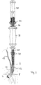
- Fig. 1 shows a cross section of the removal tool according to the invention mounted on the prosthesis socket.
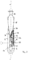
- Fig. 2 shows a single view of the assembled tool head in cross section.
- Fig. 3 shows the tool head of Fig. 2 in supervision and partially in elevation.
- Fig. 4 shows a modified embodiment of the tool head with rollers.
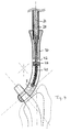
- Fig. 5 shows an alternative embodiment of Fig. 1 in cross section.
- the extraction tool shown in the figures is intended for attachment to a prosthesis shaft 4 of an articular prosthesis which is inserted or built into a bone and is to be removed from it by the extraction tool.
- the extraction tool consists of a tool head 2 which can be attached to the prosthesis neck 4 and an actuating rod 24 connected thereto, on which a striking element 26 is displaceably guided. With the rod 24 a stop 31 is also firmly connected, against which the striking element 26 is guided to produce an axially directed impact.
- the tool head 2 has a horseshoe-shaped or forked shape with a Longitudinal recess 14, which is intended for receiving various actuators 8, 10, 12, and a passage 6 widened compared to the longitudinal recess 14, which is intended for receiving the prosthetic socket 4.
- the passage 6 has a circular cross section with the exception of the intersection with the longitudinal recess 14.
- two opposite, elongated elliptically curved grooves 16 are formed, which serve to guide the actuators 8, 10, 12. As can be seen in FIG.
- the tool head 2 is continuously elliptically curved or bent in order to compensate for a curvature formed between the prosthesis socket 4 and the adjoining prosthesis main body in order to transmit the impact force transmitted by the actuating rod 24 in the axial direction of the prosthesis main body .
- the grooves 16 are adapted to the curvature of the tool head 2 and also have a curved course.
- a locking member 8 is first inserted, which has opposite longitudinal webs, which are intended to be received in the corresponding inner grooves 16 of the tool head 2. This allows the locking member 8 to be inserted axially into the tool head 2. Since the grooves are guided up to the end of the passage 6 in the tool head 2, the path of the locking member 8 inserted in the tool head 2 ends at the end of the longitudinal recess 14 or in the region of the (imaginary) supplementary line of the cross section of the passage 6. The locking member 8 leaves but push further into the passage 6 in order to effectively lock even prosthesis sockets with a smaller diameter.
- the locking member 8 has a running surface with a circular arc cross section for contacting the prosthesis socket 4.
- an actuator 10 provided with a lever 18, which has two opposite guide lugs 20 with which it is guided in the grooves 16 of the tool head 2.
- the lever 18 serves to tension the locking member 8 from a release position, in which the prosthesis neck 4 can be inserted into the passage 6, into a locking position, in which the locking member 8 is tensioned against the prosthesis neck 4 and in this position is locked.
- the actuator 10 connected to the lever 18 has an eccentric run-up surface 22 which, when the lever 18 is pivoted, leads to an increasing axial advance of the locking member 8 and subsequent locking of the locking member 8 in a substantially flat section of the running surface 22.
- an outer actuator 12 with its two opposite guide webs is plugged onto the inner grooves 16 of the tool head 2.
- the actuator 12 forms the end of the movable actuators, which thus preset the locking member 8 in its position by acting on the outer actuator 12 via the middle actuator 10.
- the release position of the locking member 8 can thus be changed by axially pressurizing the outer actuator 10.
- a connecting and closing piece 30 is pushed onto the tool head behind the outer actuator 12.
- the connecting piece 30 has laterally projecting teeth which are intended to be received in correspondingly shaped recesses 36 formed in the tool head 2.
- the connecting piece 30 is thus inserted into the tool head 2 from above and closes off the longitudinal recess 14 formed in the tool head 2 at the end opposite the passage 6.
- an elongated bore 32 is formed in the connecting piece 30, which is intended to engage an actuating rod 28.
- the connecting piece 30 is axially connected at the end to the actuating rod 24, as shown in FIG. 1.
- the actuating rod 28 is axially guided in a hollow channel of the actuating rod 24 and extends through the bore 32 of the connecting piece 30 in order to come into contact with the outer actuator 12.
- the actuating rod 28 is connected at its other end to a knob 38 which, by rotation, unscrews the actuating rod 28 from the threaded bore 32 formed in the connecting piece 30 and thus changes the axial engagement position of the locking member 8.
- the adjusting rod After insertion of the prosthesis shaft 4 into the passage 6 of the tool head 2, the adjusting rod is first advanced so far by turning the knob 38 that the locking member 8 comes into contact with the prosthesis neck 4 in the passage 6.
- the lever 18 is in its release position facing away from the tool head 2.
- the lever 18 is pivoted back out of its release position into its locking position shown in FIG. 1, which is adjacent to the connecting piece 30 or parallel to the tool head 2.
- the eccentric run-up surface 22 of the actuator 10 pushes against the locking member 8 and braces it from its release position into its locking position, where it engages in a substantially planar section of the run-up surface 22 of the actuator 10 after the locking member 8 has engaged.
- the tool head 2 is thus firmly locked to the prosthesis and the prosthesis can now be removed from the bone by striking the striking element 26 against the system 31.
- the lever 18 is pivoted out of its locking position into its release position which protrudes from the tool head 2 and in which the locking member lies in movable contact against the prosthesis shaft 4. Due to the receding contact surface 22 of the lever 18 and turning the knob 38, the locking member 8 has a game, so that the prosthesis shaft 4 can be pulled out of the passage 6 easily.
- FIG. 4 shows a tool head equipped with rollers 40, the rollers 40 being mounted and guided in the grooves 16 formed in the tool head.
- the rollers 40 thus serve as actuators arranged one behind the other, which transmit an actuating force to be transmitted axially from the actuating rod 28 to the locking member 8.
- the rollers 40 follow the curvature of the tool and are arranged in operative connection with one another.
- a push rod 42 guided in the connecting piece 30 is provided, which is connected at one end to the actuating rod 28 and at its other end has a head 44 formed with a recess, which serves to receive the rollers .
- the head 44 provides an elongated recess in which the rollers are arranged and against which the rollers are supported.
- the actuating rod 28 thus transmits through mediation the push rod 42 has an axial setting and locking force on the rollers 40. Since in this embodiment a separate locking element in the form of a lever is missing from the actuators, the locking force as well as the setting force is applied to the rollers 40 and thus to the locking element by the adjusting rod 28 8 transferred.
- the actuating rod can, for example (in a manner not shown), be connected to an eccentric lever which pushes the actuating rod 28 axially forwards or backwards by folding it over.
- the eccentric lever can be biased into a release position by spring force.
- FIG. 5 shows an alternative embodiment of the knockout tool from FIG. 1.
- a tool head 46 is connected to an actuating rod 62 on which an impact element 58 is guided.
- the striking element 58 is displaceably guided on the actuating rod 62 and comes to rest at one end of its career against a shoulder of the tool head 46, in order in this way to transmit an axial deflection increase along the tool head.
- An actuating rod 54 is movably guided in the actuating rod 62 in its inner cavity, which extends at one end into the tool head 46 and comes to rest against an actuator 52 which is axially displaceably guided in the tool head.
- a further actuator 50 and a locking member 48 are arranged, which engages in a passage formed in the tool head in order to lock an inserted prosthesis shaft.
- the actuating force of the actuating rod 54 leads to an axial displacement of the actuators or the locking element along the curved tool head 46, so that the locking element can perform its locking function.
- a handle 60 suitable for manual handling is connected to the actuating rod 62.
- the adjusting rod 54 extends through the handle 60 and out of this.
- a lever attachment is inserted into a corresponding recess in the handle Has lever member 56.
- the lever member 56 is of comparable design to the lever 18 already described above from FIG. 1, so that a detailed description of the lever member 56 can be dispensed with.
- the lever attachment is removable, so that the actuating rod 54 can also be advanced or retracted in another way.
- the handle 60 can be screwed together with the guide tube or actuating rod 62 for variable adjustment of the actuating rod 54.
Landscapes
- Health & Medical Sciences (AREA)
- Transplantation (AREA)
- Orthopedic Medicine & Surgery (AREA)
- Heart & Thoracic Surgery (AREA)
- Life Sciences & Earth Sciences (AREA)
- Oral & Maxillofacial Surgery (AREA)
- Engineering & Computer Science (AREA)
- Biomedical Technology (AREA)
- Physical Education & Sports Medicine (AREA)
- Vascular Medicine (AREA)
- Cardiology (AREA)
- Animal Behavior & Ethology (AREA)
- General Health & Medical Sciences (AREA)
- Public Health (AREA)
- Veterinary Medicine (AREA)
- Prostheses (AREA)
- Medicines That Contain Protein Lipid Enzymes And Other Medicines (AREA)
- Milling Processes (AREA)
Description
- Die vorliegende Erfindung betrifft ein Ausschlagwerkzeug für Gelenkprothesen, gemäß dem Oberbegriff des Anspruchs 1.
- Ein derartiges Ausschlagwerkzeug ist beispielsweise aus der DE 42 20 970 A1 bekannt. Der Werkzeugkopf ist gekrümmt, um eine Abwinkelung des Prothesenschaftes gegenüber einer Prothesenmittelachse auszugleichen, so daß die im Knochen eingesetzte Gelenkprothese in Verlängerung der Prothesenmittelachse herausgeschlagen werden kann. Der Krümmungswinkel des Werkzeugkopfes entspricht daher im wesentlichen der Abwinkelung des Prothesenschaftes gegenüber der Prothesenmittelachse. Eine Fehlausrichtung zwischen Ausschlagkraftvektor und Prothesenmittelachse führt zu einer Splitterung des die Gelenkprothese umgebenden Knochens, was unerwünscht ist.
- Das aus der DE 4220970 A1 bekannte Ausschlagwerkzeug hat eine Zunge, die auf einem außerhalb des Werkzeugkopfes gelagerten Hebelarm gebildet ist und zum Eingriff in eine im Prothesenschaft gebildete Ausnehmung bestimmt ist, um die Prothese am Werkzeugkopf zu verriegeln. Der Platzbedarf dieses Werkzeugs ist daher groß.
- Die Prothesenschafte gängiger Gelenkprothesen sind nicht genormt und zeigen unterschiedliche Durchmesser. Das vorbekannte Ausschlagwerkzeug berücksichtigt derartige unterschiedliche Prothesenschaftdurchmesser jedoch nicht ausreichend und die Anpassung an verschiedene Durchmesser ist aufwendig. Bei Verwendung derartiger Ausschlagwerkzeuge bei Prothesenschaften geringeren Durchmessers wird der Prothesenschaft nicht immer spielfrei und formschlüssig im Werkzeugkopf verriegelt.
- Ferner ist zu beachten, daß der im vorbekannten Ausschlagwerkzeug außerhalb des Werkzeugkopfes gelagerte Schwenkhebel den Platzbedarf des Werkzeugs erheblich erhöht. Am Operationsort steht jedoch nur ein begrenzter Raum für das Ausschlagwerkzeug zur Verfügung.
- Aufgabe der vorliegenden Erfindung ist es daher, ein gemäß Oberbegriff des Anspruchs 1 ausgebildetes Ausschlagwerkzeug derart weiterzubilden, daß unterschiedliche Prothesendurchmesser im Werkzeugkopf leicht einstellbar sind. Eine weitere Aufgabe besteht darin, daß das erfindungsgemäße Ausschlagwerkzeug einen möglichst geringen Platz einnimmt, der zweckmäßigerweise auf den Werkzeugkopf beschränkt sein sollte.
- Die Aufgabe wird gelöst durch ein Ausschlagwerkzeug nach Anspruch 1.
- Erfindungsgemäß ist somit die Freigabeposition und die Eingriffsposition des in den Durchgang eingreifenden Sperrglieds der Riegeleinrichtung so einstellbar, daß Prothesenschafte unterschiedlichen Durchmessers in den Durchgang eingeführt und in Anlage mit dem Sperrglied gebracht werden können. Die in der Freigabeposition zwischen Sperrglied und den den Durchgang definierenden Teilen des Werkzeugskopfs definierte Querschnittsfläche läßt sich somit vergrößern und verkleinern. Die Freigabeposition des Sperrglieds ist durch spielfreie Anlage des Sperrglieds am Prothesenschaft definiert, wobei das Sperrglied von dieser Freigabeposition durch ein geeignetes Mittel in die Sperrposition gespannt und fest verriegelt wird. Die für die Betätigung des Sperrglieds zur Verstellung der Freigabeposition aufgebrachte Stellkraft wird durch Stellglieder im Werkzeugkopf übertragen, so daß eine außerhalb des Werkzeugkopfs angebrachte Stelleinrichtung entfällt und die Kraftübertragung im Werkzeugkopf selbst geschieht. Auf diese Weise ist der Platzbedarf des Werkzeugkopfs minimiert.
- Es ist bevorzugt, daß der Werkzeugkopf stetig gekrümmt ist. Die stetige Krümmung des Werkzeugkopfs begünstigt die Wirkverbindung der Stellglieder, da die Stellkraft im wesentlichen axial übertragen werden kann. Die bei der Kraftübertragung wirkenden Normalkräfte sind bei einer stetigen Krümmung minimiert.
- Der Werkzeugkopf hat bevorzugt eine im Durchgang abschließende Längsausnehmung, in der die Stellglieder und das Sperrglied angeordnet und geführt sind. Dadurch läßt sich der Werkzeugkopf bequem montieren und demontieren. Die den Werkzeugkopf bildenden Einzelteile lassen sich nach der Demontage leicht sterilisieren, was für medizinische Anwendungen große Bedeutung hat.
- Die Stellglieder und das Sperrglied sind bevorzugt durch im Werkzeugkopf gebildete gegenüberliegende Nuten geführt. In diese Nuten greifen das Sperrglied und die Stellglieder mit entsprechenden Führungsnasen ein, so daß das Sperrglied und die Stellglieder axial in die Längsausnehmung des gabelförmigen Werkzeugkopfs eingeschoben und herausgezogen werden können.
- Ein Stellglied ist bevorzugt mit einem Hebel verbunden, der zum Vorschub des Sperrglieds in die Verriegelungsposition zur lösbaren Blockierung des Sperrglieds in der Verriegelungsposition dient. Hierbei wird das Sperrglied in doppelter Funktion einmal zur Übertragung der Stellkraft und zum anderen zur Übertragung der Verriegelungskraft eingesetzt. Das Sperrglied wird aus der in Anlage mit dem Prothesenschaft definierten Freigabeposition durch axiale Verspannung gegen den Prothesenschaft gedrückt und in dieser Verriegelungsposition so verriegelt, daß das Sperrglied arretiert ist und nicht zurückweichen kann. Durch die Ausbildung des Stellglieds mit Hebel entfällt eine zusätzliche Verriegelungseinrichtung für das Sperrglied und eine platzsparende Minimalanordnung wird geschaffen.
- Die Schwenkachse des Hebels ist bevorzugt im Stellglied gebildet, um eine zusätzliche Schwenkachse zu vermeiden.
- Bevorzugt weist das Stellglied eine exzentrische Auflauffläche auf, die eine vom Schwenkwinkel abhängige axiale Vorschubposition des Sperrglieds definiert. Die Auflauffläche definiert die Anlage des mit Hebel ausgebildeten Stellglieds mit dem nachfolgenden Stellglied bzw. dem Sperrglied, so daß der unterschiedliche Abstand verschiedener winkelmäßig versetzter Punkte der Auflauffläche von der Schwenkachse einen unterschiedlichen Vorschub der Auflauffläche bei der Verschwenkung des Hebels zur Folge hat.
- Das Stellglied weist bevorzugt zwei Führungsnasen auf, die längsverschieblich in den im Werkzeugkopf gebildeten Innennuten geführt sind, wobei die Führungsnasen die Schwenkachse des Hebels bilden. Die Führungsnasen haben einmal die Funktion, das Stellglied zur Übertragung der Stellkraft in den Nuten des Werkzeugkopfs zu führen. Zum anderen dienen sie als Schwenkachse des mit dem. Stellglied verbundenen Hebels, so daß wiederum eine platzsparende Minimalanordnung geschaffen ist.
- Die Stellglieder sind in einer weiteren Ausführungsform durch Kugeln oder Rollen gebildet, die miteinander in Wirkverbindung stehen. Die Kugeln folgen der Krümmung des Werkzeugkopfs in besonders platz- und kraftsparender Weise, da sie im Vergleich zur Länge des Werkzeugkopfs geringen Durchmesser haben.
- Bevorzugt ist mit dem Werkzeugkopf eine Betätigungsstange verbunden, auf der ein Schlagelement verschieblich geführt ist. Das Schlagelement schlägt gegen einen an der Betätigungsstange befestigten Anschlag an, so daß der auf diesen Anschlag aufgebrachte Stoß unmittelbar über den Werkzeugkopf und den Prothesenschaft auf den Prothesen-Hauptkörper übertragen wird, so daß sich dieser aus dem Knochen löst.
- In der Betätigungsstange ist bevorzugt eine Stellstange verschieblich geführt, die mit dem Werkzeugkopf so verbunden ist, daß die Stellkraft auf ein äußeres Stellglied des Werkzeugkopfes aufgebracht wird. Die Stellstange ist in der hohl ausgebildeten Betätigungsstange verschieblich geführt, bevorzugt durch ein Gewinde, so daß durch Verdrehen eines mit der Stellstange verbundenen Knopfes die Stellstange axial gegen das äußere Stellglied geführt wird und dieses in axialer Richtung vorschiebt. Nach Übertragung durch die weiteren Stellglieder erreicht somit die durch die Stellstange aufgebrachte Stellkraft das Sperrglied.
- In einer weiteren Ausführungsform, die auf die genannte Ausführungsform mit Kugel oder Rollen Bezug nimmt, dient die Stellstange bevorzugt zugleich zur Einstellung der Eingriffsposition des Sperrglieds zwecks Anpassung an unterschiedliche Prothesenschaftdurchmesser und zu dessen Verriegelung. Hier entfällt ein mit einem Stellglied verbundener Hebel und die zur Betätigung des Sperrglieds auf die Stellglieder aufgebrachte Stellkraft wirkt in entsprechender Dimensionierung auch zur Verspannung des Sperrglieds in die Verriegelungsposition und zur Verriegelung des Sperrglieds in dieser Position. Zu diesem Zweck kann beispielsweise die Stellstange, die in der Betätigungsstange geführt ist, so ausgebildet werden, daß sie durch einen Exzenterhebel oder dergleichen gespannt und entspannt werden kann.
- In einer weiterhin bevorzugten Ausführungsform ist an einem Ende der Stellstange ein Hebelglied angeordnet, das mit der Stellstange derart in Wirkverbindung steht, daß eine Verschwenkung des Hebelgliedes die Stellstange in Richtung des Werkzeugkopfes vorschiebt. Auf diese Weise wird die durch das Hebelglied erzeugte Stellkraft längst der Stellstange und entlang der Stellglieder auf das Sperrglied übertragen. Die Anordnung eines Hebelgliedes an einem dem Werkzeugkopf gegenüberliegenden Ende der Stellstange schafft die Möglichkeit einer besonders platzsparenden und ergonomisch wirkungsvollen Betätigung des Ausschlagwerkzeuges.
- Durch Verschwenkung des Hebelgliedes kann die Stellstange in Richtung des Werkzeugkopfes vorgespannt oder gelöst werden.
- Bevorzugt ist das Hebelglied abnehmbar, so daß auch alternative Vorspannungseinrichtungen aufgesetzt werden können.
- Weitere Vorteile, Merkmale und Anwendungsmöglichkeiten der vorliegenden Erfindung ergeben sich aus der nachfolgenden Beschreibung eines bevorzugten Ausführungsbeispiels in Verbindung mit der Zeichnung.
- Fig. 1 zeigt einen Querschnitt des auf dem Prothesenschaft montierten erfindungsgemäßen Ausschlagwerkzeugs.
- Fig. 2 zeigt eine Einzelansicht des montierten Werkzeugkopfes im Querschnitt.
- Fig. 3 zeigt den Werkzeugkopf von Fig. 2 in Aufsicht und teilweise in Aufriß.
- Fig. 4 zeigt eine modifizierte Ausführungsform des Werkzeugkopfes mit Rollen.
- Fig. 5 zeigt eine alternative Ausführungsform von Fig. 1 im Querschnitt.
- Das in den Figuren dargestellte Ausschlagwerkzeug ist zur Befestigung an einem Prothesenschaft 4 einer Gelenkprothese bestimmt, die in einem Knochen eingesetzt bzw. eingebaut ist und durch das Ausschlagwerkzeug aus diesem entfernt werden soll.
- Das Ausschlagwerkzeug besteht aus einem am Prothesenhals 4 befestigbaren Werkzeugkopf 2 und einer damit verbundenen Betätigungsstange 24, auf der ein Schlagelement 26 verschieblich geführt ist. Mit der Stange 24 ist ferner ein Anschlag 31 fest verbunden, gegen den das Schlagelement 26 zur Erzeugung eines axial gerichteten Stoßes geführt wird.
- Der Werkzeugkopf 2 hat hufeisenförmige bzw. gabelförmige Gestalt mit einer Längsausnehmung 14, die zur Aufnahme verschiedener Stellglieder 8, 10, 12 bestimmt ist, und einem gegenüber der Längsausnehmung 14 verbreiterten Durchgang 6, der zur Aufnahme des Prothesenschaftes 4 bestimmt ist. Der Durchgang 6 hat kreisförmigen Querschnitt mit Ausnahme des Schnittbereichs mit der Längsausnehmung 14. In den der Längsausnehmung 14 zugewandten Seitenwänden des Werkzeugkopfes 2 sind zwei gegenüberliegende längsgestreckte elliptisch gekrümmte Nuten 16 gebildet, die zur Führung der Stellglieder 8, 10, 12 dienen. Der Werkzeugkopf 2 ist, wie in Fig. 1 zu sehen, elliptisch stetig gekrümmt bzw. gebogen, um eine zwischen dem Prothesenschaft 4 und dem daran anschließenden Prothesenhauptkörper gebildete Krümmung auszugleichen, um die durch die Betätigungsstange 24 übertragene Stoßkraft in axialer Richtung des Prothesenhauptkörpers zu übertragen. Die Nuten 16 sind der Krümmung des Werkzeugkopfes 2 angepaßt und haben ebenfalls einen gebogenen Verlauf.
- In die Ausnehmung 14 wird zunächst ein Sperrglied 8 eingeführt, das gegenüberliegende Längsstege hat, die zur Aufnahme in den entsprechenden Innennuten 16 des Werkzeugkopfes 2 bestimmt sind. Dadurch läßt sich das Sperrglied 8 axial in den Werkzeugkopf 2 einführen. Da die Nuten bis zum Ende des Durchgangs 6 im Werkzeugkopf 2 geführt sind, endet die Bahn des in dem Werkzeugkopf 2 eingeführten Sperrglieds 8 am Ende der Längsausnehmung 14 bzw. im Bereich der (gedachten) Ergänzungslinie des Querschnitts des Durchgangs 6. Das Sperrglied 8 läßt sich jedoch noch weiter in den Durchgang 6 hinein vorschieben, um auch Prothesenschafte mit kleinerem Durchmesser wirksam zu verriegeln. Zur Anpassung an den kreisförmigen Querschnitt des Prothesenschaftes 4 besitzt das Sperrglied 8 eine im Querschnitt kreisbogenförmige Auflauffläche zur Anlage an dem Prothesenschaft 4.
- Hinter dem Sperrglied 8 wird ebenfalls axial ein mit einem Hebel 18 versehenes Stellglied 10 eingeführt, das zwei gegenüberliegende Führungsnasen 20 aufweist, mit denen es in den Nuten 16 des Werkzeugkopfs 2 geführt ist. Der Hebel 18 dient zur Verspannung des Sperrglieds 8 von einer Freigabeposition, in der der Prothesenhals 4 in den Durchgang 6 eingeführt werden kann, in eine Verriegelungsposition, in der das Sperrglied 8 gegen den Prothesenhals 4 gespannt und in dieser Stellung verriegelt ist. Zu diesem Zweck weist das mit dem Hebel 18 verbundene Stellglied 10 eine exzentrische Auflauffläche 22 auf, die bei Verschwenkung des Hebels 18 zu einem wachsenden axialen Vorschub des Sperrglieds 8 und anschließendem Einrasten des Sperrglieds 8 in einem im wesentlichen planen Abschnitt der Auflauffläche 22 führt.
- Hinter dem Stellglied 10 wird ein äußeres Stellglied 12 mit seinen zwei gegenüberliegenden Führungsstegen auf den Innennuten 16 des Werkzeugkopfs 2 aufgesteckt. Das Stellglied 12 bildet den Abschluß der beweglichen Stellglieder, die somit durch Beaufschlagung des äußeren Stellglieds 12 über Vermittlung des mittleren Stellglieds 10 das Sperrglied 8 in seiner Position voreinstellen. Die Freigabeposition des Sperrglieds 8 läßt sich somit durch axiale Druckbeaufschlagung des äußeren Stellglieds 10 verändern. Am Abschluß des Werkzeugkopfs 2 wird hinter dem äußeren Stellglied 12 ein Verbindungs- und Abschlußstück 30 auf den Werkzeugkopf aufgeschoben. Das Verbindungsstück 30 weist seitlich vorspringende Zähne auf, die zur Aufnahme in entsprechend geformten im Werkzeugkopf 2 gebildeten Ausnehmungen 36 bestimmt sind. Das Verbindungsstück 30 wird somit von oben in den Werkzeugkopf 2 eingeführt und schließt die im Werkzeugkopf 2 gebildete Längsausnehmung 14 an dem dem Durchgang 6 gegenüberliegenden Ende ab. Zur Betätigung des äußeren Stellglieds 12 ist in dem Verbindungsstück 30 eine längsgestreckte Bohrung 32 gebildet, die zum Eingriff einer Stellstange 28 bestimmt ist.
- Das Verbindungsstück 30 ist axial endseitig mit der Betätigungsstange 24 verbunden, wie in Fig. 1 gezeigt. In einem Hohlkanal der Betätigungsstange 24 ist die Stellstange 28 axial geführt, die durch die Bohrung 32 des Verbindungsstücks 30 hindurchgreift, um in Anlage gegen das äußere Stellglied 12 zu gelangen. Die Stellstange 28 ist an ihrem anderen Ende mit einem Knauf 38 verbunden, der durch Drehung die Stellstange 28 aus der im Verbindungsstück 30 gebildeten Gewindebohrung 32 herausdreht und somit die axiale Eingriffsposition des Sperrglieds 8 verändert.
- Nach Einführung des Prothesenschaftes 4 in den Durchgang 6 des Werkzeugkopfes 2 wird zunächst durch Drehen des Knauffes 38 die Stellstange so weit vorgeschoben, daß das Sperrglied 8 in Anlage an den Prothesenhals 4 in dem Durchgang 6 gelangt. Der Hebel 18 befindet sich dabei in seiner vom Werkzeugkopf 2 weggerichteten Freigabeposition. Nach Anlage des Sperrglieds 8 am Prothesenschaft 4 wird der Hebel 18 aus seiner Freigabestellung in seine in Fig. 1 gezeigte Verriegelungsposition, die dem Verbindungsstück 30 benachbart bzw. parallel zum Werkzeugkopf 2 ausgerichtet ist, zurückgeschwenkt. Dabei schiebt sich die exzentrische Auflauffläche 22 des Stellglieds 10 gegen das Sperrglied 8 und verspannt dieses aus seiner Freigabeposition in seine Verriegelungsposition, wo es nach Einrasten des Sperrglieds 8 an einem im wesentlichen planen Abschnitt der Auflauffläche 22 des Stellglieds 10 einrastet. Damit ist der Werkzeugkopf 2 fest an der Prothese verriegelt und die Prothese kann nun durch Schläge des Schlagelements 26 gegen die Anlage 31 aus dem Knochen entfernt werden. Zur Lösung von Werkzeugkopf 2 und Prothesenschaft 4 wird der Hebel 18 aus seiner Verriegelungsstellung in seine vom Werkzeugkopf 2 abstehende Freigabeposition verschwenkt, in der das Sperrglied in beweglicher Anlage gegen den Prothesenschaft 4 liegt. Durch die zurückweichende Auflauffläche 22 des Hebels 18 und Drehen des Knaufes 38 bekommt das Sperrglied 8 ein Spiel, so daß der Prothesenschaft 4 bequem aus dem Durchgang 6 herausgezogen werden kann.
- Die in Fig. 4 gezeigte Modifikation des erfindungsgemäßen Ausschlagwerkzeugs zeigt einen mit Rollen 40 bestückten Werkzeugkopf, wobei die Rollen 40 in den im Werkzeugkopf gebildeten Nuten 16 gelagert und geführt sind. Die Rollen 40 dienen somit als hintereinander angeordnete Stellglieder, die eine axial von der Stellstange 28 zu übertragende Stellkraft auf das Sperrglied 8 übertragen. Die Rollen 40 folgen der Krümmung des Werkzeugs und sind in Wirkverbindung miteinander angeordnet.
- Zur Verbindung der Stellstange 28 und der Rollen 40 ist eine im Verbindungsstück 30 geführte Schubstange 42 vorgesehen, die an ihrem einen Ende mit der Stellstange 28 verbunden ist und an ihrem anderen Ende einen mit einer Vertiefung gebildeten Kopf 44 aufweist, der zur Aufnahme der Rollen dient. Der Kopf 44 sieht eine längsgestreckte Vertiefung vor, in der die Rollen angeordnet sind und gegen die die Rollen sich abstützen. Die Stellstange 28 überträgt somit durch Vermittlung der Schubstange 42 eine axiale Einstell- und Verriegelungskraft auf die Rollen 40. Da in dieser Ausführungsform ein separates Verriegelungselement in Form eines Hebels bei den Stellgliedern fehlt, wird die Verriegelungskraft ebenso wie die Einstellkraft durch die Stellstange 28 auf die Rollen 40 und damit auf das Sperrglied 8 übertragen. Somit wird ausschließlich über einen axialen Vorschub der Stellstange 28 die Einstellung der Eingriffsposition und die Verriegelung des Sperrglieds in der Verriegelungsposition bewirkt. Die Stellstange kann beispielsweise (in nicht gezeigter Weise) mit einem Exzenterhebel verbunden sein, der durch Umlegen die Stellstange 28 axial vor- oder zurückschiebt. Der Exzenterhebel kann durch Federkraft in eine Freigabeposition vorgespannt sein.
- In Fig. 5 ist eine alternative Ausführungsform des Ausschlagwerkzeugs von Fig. 1 gezeigt. Ein Werkzeugkopf 46 ist mit einer Betätigungsstange 62 verbunden, auf der ein Schlagelement 58 geführt ist. Das Schlagelement 58 ist auf der Betätigungsstange 62 verschieblich geführt und kommt an einem Ende seiner Laufbahn zur Anlage gegen eine Schulter des Werkzeugkopfes 46, um auf diese Weise einen axialen Ausschlagimplus längst des Werkzeugkopfes zu übertragen. In der Betätigungsstange 62 ist in ihrem inneren Hohlraum eine Stellstange 54 beweglich geführt, die sich an ihrem einen Ende in den Werkzeugkopf 46 hinein erstreckt und zur Anlage gegen ein im Werkzeugkopf axial verschieblich geführtes Stellglied 52 gelangt. Im Werkzeugkopf 46 sind neben dem Stellglied 52 in Anlage mit diesem ein weiteres Stellglied 50 und daran anliegend ein Sperrglied 48 angeordnet, welches in einen im Werkzeugkopf gebildeten Durchgang eingreift, um einen eingeführten Prothesenschaft zu verriegeln. Die Stellkraft der Stellstange 54 führt zu einer axialen Verschiebung der Stellglieder bzw. des Sperrgliedes entlang des gekrümmten Werkzeugkopfes 46, so daß das Sperrglied seine Verriegelungsfunktion ausüben kann. An dem dem Werkzeugkopf 46 gegenüberliegenden Ende der Betätigungsstange 62 ist ein zur manuellen Handhabung geeigneter Griff 60 mit der Betätigungsstange 62 verbunden. Die Stellstange 54 streckt sich durch den Griff 60 hindurch und aus diesem heraus.
- An dem Griff ist an dem der Betätigungsstange 62 gegenüberliegenden Ende ein Hebelaufsatz in eine entsprechende Vertiefung des Griffes eingesetzt, der ein Hebelglied 56 aufweist. Das Hebelglied 56 ist dem bereits vorstehend beschriebenen Hebel 18 aus Fig. 1 vergleichbar ausgebildet, so daß auf eine detallierte Beschreibung des Hebelglieds 56 verzichtet werden kann. Im Ergebnis wird durch Einrichtung einer exzentrischen Auflauffläche am Hebelglied 56 dieses in die Lage versetzt, durch Verschwenken eine axial gerichtete Stellkraft auf die Stellstange 54 auszuüben, wodurch das Sperrglied 48 im Werkzeugkopf 46 vorgeschoben und in Eingriff mit der Ausnehmung geführt wird. Der Hebelaufsatz ist abnehmbar, so daß die Stellstange 54 auch auf andere Weise vorgeschoben bzw. zurückgezogen werden kann.
- Der Griff 60 ist zusammenschraubbar mit dem Führungsrohr bzw. Betätigungsstange 62 zur variablen Einstellung der Stellstange 54.
Claims (10)
- Ausschlagwerkzeug für Gelenkprothesen, mit einem gekrümmten Werkzeugkopf (2), der einen Durchgang (6) zur Aufnahme eines Prothesenschaftes (4) und eine Riegeleinrichtung (8, 10, 12) aufweist, die den Prothesenschaft (4) im Durchgang (6) lösbar blockiert, wobei die Riegeleinrichtung ein in den Durchgang (6) eingreifendes Sperrglied (8) aufweist, dadurch gekennzeichnet, daß das Sperrglied (8) durch innerhalb des Werkzeugkopfes (2) axial verschieblich angeordnete Stellglieder (10, 12; 40) verstellbar ist, wobei eine auf das Sperrglied (8) wirkende Stellkraft axial entlang der Stellglieder (10, 12; 40) übertragen wird.
- Ausschlagwerkzeug nach Anspruch 1, dadurch gekennzeichnet, daß der Werkzeugkopf (2) stetig gekrümmt ist und eine im Durchgang (6) sich öffnende axiale Längsausnehmung (14) aufweist, in der die Stellglieder (10, 12; 40) und das Sperrglied (8) angeordnet sind.
- Ausschlagwerkzeug nach Anspruch 2, dadurch gekennzeichnet, daß die Stellglieder (10, 12) und das Sperrglied (8) durch im Werkzeugkopf (2) gebildete gegenüberliegende Nuten (16) geführt sind.
- Ausschlagwerkzeug nach einem der vorhergehenden Ansprüche, dadurch gekennzeichnet, daß ein Stellglied (10) mit einem Hebel (18) verbunden ist, der zum Vorschub des Sperrglieds (8) in die Verriegelungsposition und zur lösbaren Blockierung des Sperrglieds in der Verriegelungsposition dient, wobei die Schwenkachse (20) des Hebels (18) im Stellglied (10) gebildet ist.
- Ausschlagwerkzeug nach einem der vorhergehenden Ansprüche, dadurch gekennzeichnet, daß die Stellglieder durch Kugeln oder Rollen (40) gebildet sind.
- Ausschlagwerkzeug nach einem der vorhergehenden Ansprüche, dadurch gekennzeichnet, daß mit dem Werkzeugkopf (2) eine Betätigungsstange (24, 62) verbunden ist, auf der ein Schlagelement (26, 58) verschieblich geführt ist.
- Ausschlagwerkzeug nach Anspruch 6, dadurch gekennzeichnet, daß in der Betätigungsstange (24, 62) eine Stellstange (28, 54) verschieblich geführt ist, die mit dem Werkzeugkopf (2) so verbunden ist, daß die Stellkraft auf ein äußeres Stellglied (12) des Werkzeugskopfs (2) aufgebracht wird.
- Ausschlagwerkzeug nach Anspruch 7, dadurch gekennzeichnet, daß die Stellstange (28, 54) zugleich zur Einstellung der Eingriffsposition des Sperrglieds (8) zwecks Anpassung an unterschiedliche Prothesenschaftdurchmesser und zur Verriegelung des Sperrglieds (8) dient.
- Ausschlagwerkzeug nach einem der vorherhegenden Ansprüche, dadurch gekennzeichnet, daß an einem Ende der Stellstange (54) ein Hebelglied (56) angeordnet ist, das mit der Stellstange (54) derart in Wirkverbindung steht, daß eine Verschwenkung des Hebelgliedes (56) die Stellstange (54) in Richtung des Werkzeugkopfes vorschiebt.
- Ausschlagwerkzeug nach Anspruch 9, dadurch gekennzeichnet, daß das Hebelglied (56) abnehmbar ist.
Applications Claiming Priority (2)
| Application Number | Priority Date | Filing Date | Title |
|---|---|---|---|
| DE4332872 | 1993-09-27 | ||
| DE4332872A DE4332872C1 (de) | 1993-09-27 | 1993-09-27 | Ausschlagwerkzeug für Gelenkprothesen |
Publications (2)
| Publication Number | Publication Date |
|---|---|
| EP0645127A1 EP0645127A1 (de) | 1995-03-29 |
| EP0645127B1 true EP0645127B1 (de) | 1996-01-17 |
Family
ID=6498756
Family Applications (1)
| Application Number | Title | Priority Date | Filing Date |
|---|---|---|---|
| EP94114466A Expired - Lifetime EP0645127B1 (de) | 1993-09-27 | 1994-09-14 | Ausschlagwerkzeug für Gelenkprothesen |
Country Status (6)
| Country | Link |
|---|---|
| US (1) | US5534006A (de) |
| EP (1) | EP0645127B1 (de) |
| AT (1) | ATE133059T1 (de) |
| CA (1) | CA2132906A1 (de) |
| DE (2) | DE4332872C1 (de) |
| HU (1) | HU213773B (de) |
Cited By (2)
| Publication number | Priority date | Publication date | Assignee | Title |
|---|---|---|---|---|
| US9526512B2 (en) | 2003-11-18 | 2016-12-27 | Smith & Nephew, Inc. | Universal double offset surgical instrument |
| US12208021B2 (en) | 2018-10-04 | 2025-01-28 | Depuy Ireland Unlimited Company | Prosthesis extraction system |
Families Citing this family (57)
| Publication number | Priority date | Publication date | Assignee | Title |
|---|---|---|---|---|
| FR2742334B1 (fr) * | 1995-12-18 | 1998-05-15 | Maurice Lanzoni | Dispositif developpeur d'effort d'un prehenseur universel de tige femorale |
| FR2749501B1 (fr) * | 1996-06-05 | 1998-08-07 | Sferic | Dispositif d'extraction de tiges medullaires |
| DE19647954A1 (de) * | 1996-11-20 | 1998-06-04 | Hoechst Ag | Biaxial orientierte Folie aus cycloolefinischen Polymeren, Verfahren zu deren Herstellung und deren Verwendung |
| US5951564A (en) * | 1996-12-18 | 1999-09-14 | Bristol-Myers Squibb Company | Orthopaedic positioning apparatus |
| FR2770128B1 (fr) * | 1997-10-24 | 2000-11-17 | Aesculap Sa | Systeme de prothese de hanche |
| US6113605A (en) * | 1998-03-02 | 2000-09-05 | Benoist Girard & Cie | Prosthesis inserter |
| US6626913B1 (en) | 1999-03-03 | 2003-09-30 | Smith & Nephew, Inc. | Methods, systems, and instruments for inserting prosthetic implants |
| US6179840B1 (en) | 1999-07-23 | 2001-01-30 | Ethicon, Inc. | Graft fixation device and method |
| US20020095157A1 (en) | 1999-07-23 | 2002-07-18 | Bowman Steven M. | Graft fixation device combination |
| US7214232B2 (en) * | 1999-07-23 | 2007-05-08 | Ethicon, Inc. | Graft fixation device |
| US6423073B2 (en) * | 1999-07-23 | 2002-07-23 | Ethicon, Inc. | Instrument for inserting graft fixation device |
| US6991656B2 (en) * | 2000-04-26 | 2006-01-31 | Dana Mears | Method and apparatus for performing a minimally invasive total hip arthroplasty |
| US6814738B2 (en) | 2001-01-23 | 2004-11-09 | Depuy Acromed, Inc. | Medical impacting device and system |
| US6709439B2 (en) | 2001-10-30 | 2004-03-23 | Depuy Spine, Inc. | Slaphammer tool |
| US7390327B2 (en) * | 2003-10-03 | 2008-06-24 | Howmedica Osteonics Corp. | Punch apparatus and method for surgery |
| CA2548831C (en) | 2003-11-18 | 2012-08-14 | Smith & Nephew, Inc. | Surgical technique and instrumentation for minimal incision hip arthroplasty surgery |
| DE112005003826A5 (de) * | 2005-12-15 | 2008-11-20 | Müller, Erich Johann, Dr. med. | Chirurgisches Werkzeug und Verfahren |
| US7621921B2 (en) * | 2006-01-25 | 2009-11-24 | Symmetry Medical, Inc | Split thread orthopaedic implant impactor |
| US7935125B2 (en) | 2006-03-06 | 2011-05-03 | Howmedica Osteonics Corp. | Compound offset handle |
| US20070288096A1 (en) * | 2006-06-02 | 2007-12-13 | Gabriel Surma | System and method for inserting an implant |
| DE102013200924A1 (de) * | 2013-01-22 | 2014-07-24 | Erich Johann Müller | Ausschlagwerkzeug für minimalinvasive Prothesenrevision |
| US12023253B2 (en) | 2014-01-24 | 2024-07-02 | Howmedica Osteonics Corp. | Humeral implant anchor system |
| US10456264B2 (en) | 2014-01-24 | 2019-10-29 | Tornier, Inc. | Humeral implant anchor system |
| US10405911B2 (en) * | 2015-03-19 | 2019-09-10 | Louis FERREIRA | Long stem implant extraction tool |
| US11458028B2 (en) | 2016-01-11 | 2022-10-04 | Kambiz Behzadi | Prosthesis installation and assembly |
| US11291426B2 (en) | 2016-01-11 | 2022-04-05 | Kambiz Behzadi | Quantitative assessment of implant bone preparation |
| US11234840B2 (en) | 2016-01-11 | 2022-02-01 | Kambiz Behzadi | Bone preparation apparatus and method |
| US11298102B2 (en) | 2016-01-11 | 2022-04-12 | Kambiz Behzadi | Quantitative assessment of prosthesis press-fit fixation |
| US11534314B2 (en) | 2016-01-11 | 2022-12-27 | Kambiz Behzadi | Quantitative assessment of prosthesis press-fit fixation |
| US12193951B2 (en) | 2016-01-11 | 2025-01-14 | Kambiz Behzadi | Quantitative assessment of prosthesis press-fit fixation |
| US10463505B2 (en) | 2016-01-11 | 2019-11-05 | Kambiz Behzadi | Bone preparation apparatus and method |
| US11751807B2 (en) | 2016-01-11 | 2023-09-12 | Kambiz Behzadi | Invasive sense measurement in prosthesis installation and bone preparation |
| US11375975B2 (en) | 2016-01-11 | 2022-07-05 | Kambiz Behzadi | Quantitative assessment of implant installation |
| US11399946B2 (en) | 2016-01-11 | 2022-08-02 | Kambiz Behzadi | Prosthesis installation and assembly |
| US20170196707A1 (en) | 2016-01-11 | 2017-07-13 | Kambiz Behzadi | Surgical impaction centering apparatus and method |
| US11109802B2 (en) | 2016-01-11 | 2021-09-07 | Kambiz Behzadi | Invasive sense measurement in prosthesis installation and bone preparation |
| US10441244B2 (en) | 2016-01-11 | 2019-10-15 | Kambiz Behzadi | Invasive sense measurement in prosthesis installation |
| US10849766B2 (en) | 2016-01-11 | 2020-12-01 | Kambiz Behzadi | Implant evaluation in prosthesis installation |
| US11331069B2 (en) | 2016-01-11 | 2022-05-17 | Kambiz Behzadi | Invasive sense measurement in prosthesis installation |
| US11026809B2 (en) | 2016-01-11 | 2021-06-08 | Kambiz Behzadi | Prosthesis installation and assembly |
| US11241248B2 (en) | 2016-01-11 | 2022-02-08 | Kambiz Behzadi | Bone preparation apparatus and method |
| US10251663B2 (en) | 2016-01-11 | 2019-04-09 | Kambiz Behzadi | Bone preparation apparatus and method |
| US10426540B2 (en) | 2016-01-11 | 2019-10-01 | Kambiz Behzadi | Prosthesis installation |
| US10463499B2 (en) | 2016-03-25 | 2019-11-05 | Tornier, Inc. | Stemless shoulder implant with fixation components |
| WO2018022227A1 (en) | 2016-07-28 | 2018-02-01 | Tornier, Inc. | Stemless prosthesis anchor component |
| EP3687454B1 (de) | 2017-09-25 | 2025-05-07 | Howmedica Osteonics Corp. | Patientenspezifische stiellose ankerprothesenkomponente |
| US11399948B2 (en) | 2017-12-11 | 2022-08-02 | Howmedica Osteonics Corp. | Stemless prosthesis anchor components and kits |
| DE202018103170U1 (de) | 2018-06-06 | 2018-06-13 | Erich Johann Müller | Modulares chirurgisches Instrument |
| CA3114808A1 (en) | 2018-10-02 | 2020-04-09 | Tornier, Inc. | Shoulder prosthesis components and assemblies |
| US11969336B2 (en) | 2018-10-08 | 2024-04-30 | Kambiz Behzadi | Connective tissue grafting |
| US11622869B2 (en) * | 2019-07-29 | 2023-04-11 | Tri-Sphere Holdings | Femoral component extractor |
| JP7434538B2 (ja) | 2019-10-01 | 2024-02-20 | ハウメディカ オステオニクス コーポレイション | 肩プロテーゼコンポーネント及び肩プロテーゼ組立体 |
| US11779468B2 (en) * | 2020-04-14 | 2023-10-10 | Shukla Medical | Implant extractor |
| US11617660B2 (en) * | 2020-06-12 | 2023-04-04 | Tri-Sphere Holdings, LLC | Femoral component extractor |
| US12453643B2 (en) * | 2021-07-02 | 2025-10-28 | Shukla Medical | Implant extractor |
| FR3133123B1 (fr) | 2022-03-07 | 2024-03-01 | Claude Majou | Dispositif d’extraction d’un element prothetique telle une tige femorale |
| US20240325168A1 (en) * | 2023-03-29 | 2024-10-03 | DePuy Synthes Products, Inc. | Orthopaedic surgical instrument for extracting a femoral stem component in a hip replacement surgical procedure and method of using the same |
Family Cites Families (8)
| Publication number | Priority date | Publication date | Assignee | Title |
|---|---|---|---|---|
| US4222382A (en) * | 1979-01-26 | 1980-09-16 | Massachusetts Institute Of Technology | Femoral component hip joint prosthesis extractor |
| FR2615097B1 (fr) * | 1987-05-12 | 1989-08-18 | Landos Applic Orthopediques Fs | Impacteur-extracteur de prothese notamment de hanche |
| FR2627983B1 (fr) * | 1988-03-02 | 1997-05-16 | Vecteur Orthopedic Sa | Dispositif de mise en place de protheses femorales de hanches |
| US4993410A (en) * | 1989-05-01 | 1991-02-19 | Kimsey Timothy P | Prosthetic removal device |
| DE3935518A1 (de) * | 1989-10-25 | 1991-05-02 | Man Technologie Gmbh | Vorrichtung zum halten von prothesen fuer die im- und explantation der prothese |
| CH685471A5 (de) * | 1991-06-26 | 1995-07-31 | Sulzer Ag | Ausschlaginstrument für Hüftgelenkprothesenschäfte. |
| DE4220970A1 (de) * | 1991-12-30 | 1993-07-01 | Artos Med Produkte | Ausschlaginstrument |
| FR2686016B1 (fr) * | 1992-01-15 | 1994-04-08 | Icp France | Appareil d'extraction d'un culot de ciment femoral d'une prothese. |
-
1993
- 1993-09-27 DE DE4332872A patent/DE4332872C1/de not_active Expired - Fee Related
-
1994
- 1994-09-14 EP EP94114466A patent/EP0645127B1/de not_active Expired - Lifetime
- 1994-09-14 DE DE59400090T patent/DE59400090D1/de not_active Expired - Fee Related
- 1994-09-14 AT AT94114466T patent/ATE133059T1/de not_active IP Right Cessation
- 1994-09-23 HU HU9402731A patent/HU213773B/hu not_active IP Right Cessation
- 1994-09-26 CA CA002132906A patent/CA2132906A1/en not_active Abandoned
- 1994-09-27 US US08/313,462 patent/US5534006A/en not_active Expired - Lifetime
Cited By (2)
| Publication number | Priority date | Publication date | Assignee | Title |
|---|---|---|---|---|
| US9526512B2 (en) | 2003-11-18 | 2016-12-27 | Smith & Nephew, Inc. | Universal double offset surgical instrument |
| US12208021B2 (en) | 2018-10-04 | 2025-01-28 | Depuy Ireland Unlimited Company | Prosthesis extraction system |
Also Published As
| Publication number | Publication date |
|---|---|
| HUT69452A (en) | 1995-09-28 |
| EP0645127A1 (de) | 1995-03-29 |
| HU213773B (en) | 1997-10-28 |
| ATE133059T1 (de) | 1996-02-15 |
| DE4332872C1 (de) | 1995-04-06 |
| CA2132906A1 (en) | 1995-03-28 |
| HU9402731D0 (en) | 1994-12-28 |
| DE59400090D1 (de) | 1996-02-29 |
| US5534006A (en) | 1996-07-09 |
Similar Documents
| Publication | Publication Date | Title |
|---|---|---|
| EP0645127B1 (de) | Ausschlagwerkzeug für Gelenkprothesen | |
| EP0860148B1 (de) | Bajonettkupplung zum lösbaren Verbinden zweier Rohrschaftinstrumente oder -instrumententeile | |
| EP1014879B1 (de) | Schraubendreher für medizinische zwecke | |
| EP1889579B1 (de) | Medizinisches Rohrschaftinstrument | |
| EP1212983B1 (de) | Chirurgisches Instrument | |
| WO2009098589A1 (de) | Zerlegbares chirurgisches instrument | |
| DE10064623C1 (de) | Zange für endoskopische Chirurgie | |
| EP3213700B1 (de) | Medizinisches instrument | |
| EP1339332B1 (de) | Medizinisches instrument | |
| EP4054447B1 (de) | Medizinisches schiebeschaftinstrument | |
| EP2785262B1 (de) | Chirurgischer handgriff sowie chirurgisches rohrschaftinstrument mit einem chirurgischen handgriff | |
| DE102008064518B4 (de) | Chirurgischer Raspelgriff und chirurgische Raspel | |
| DE202011000828U1 (de) | Chirurgischer Instrumentenschaft und chirurgisches Instrument | |
| EP2258285B1 (de) | Medizinische Stanze | |
| DE102005016869A1 (de) | Medizinisches Handstück mit einer Spannzange | |
| DE202011052176U1 (de) | Chirurgischer Handgriff sowie chirurgisches Rohrschaftinstrument mit einem chirurgischen Handgriff | |
| DE102006016214A1 (de) | Chirurgischer Instrumentengriff und chirurgisches Instrument | |
| EP3621535A1 (de) | Chirurgisches instrument mit verbesserter schliesscharakteristik | |
| DE4421585C1 (de) | Chirurgisches Rohrschaftinstrument | |
| EP0688534B1 (de) | Chirurgisches Rohrschaftinstrument | |
| DE202007000425U1 (de) | Chirurgisches Instrument | |
| DE102022125213B4 (de) | Kupplungsvorrichtung und Griffvorrichtung für ein chirurgisches Instrument, chirurgisches Instrument sowie Verfahren zum Zusammenbau und Verfahren zur Demontage des chirurgischen Instruments | |
| EP4311510B1 (de) | Medizinisches schlaginstrument | |
| DE202006005632U1 (de) | Chirurgischer Instrumentengriff und chirurgisches Instrument | |
| EP1941840B1 (de) | Chirurgisches Instrument |
Legal Events
| Date | Code | Title | Description |
|---|---|---|---|
| PUAI | Public reference made under article 153(3) epc to a published international application that has entered the european phase |
Free format text: ORIGINAL CODE: 0009012 |
|
| AK | Designated contracting states |
Kind code of ref document: A1 Designated state(s): AT BE CH DE DK ES FR GB GR IE IT LI LU NL PT SE |
|
| 17P | Request for examination filed |
Effective date: 19950329 |
|
| 17Q | First examination report despatched |
Effective date: 19950607 |
|
| RAP3 | Party data changed (applicant data changed or rights of an application transferred) |
Owner name: SZABO, ZSOLT |
|
| RBV | Designated contracting states (corrected) |
Designated state(s): AT BE CH DE DK ES FR GB GR IE IT LI LU NL PT SE |
|
| GRAA | (expected) grant |
Free format text: ORIGINAL CODE: 0009210 |
|
| AK | Designated contracting states |
Kind code of ref document: B1 Designated state(s): AT BE CH DE DK ES FR GB GR IE IT LI LU NL PT SE |
|
| PG25 | Lapsed in a contracting state [announced via postgrant information from national office to epo] |
Ref country code: NL Free format text: LAPSE BECAUSE OF FAILURE TO SUBMIT A TRANSLATION OF THE DESCRIPTION OR TO PAY THE FEE WITHIN THE PRESCRIBED TIME-LIMIT Effective date: 19960117 Ref country code: IT Free format text: LAPSE BECAUSE OF FAILURE TO SUBMIT A TRANSLATION OF THE DESCRIPTION OR TO PAY THE FEE WITHIN THE PRESCRIBED TIME-LIMIT;WARNING: LAPSES OF ITALIAN PATENTS WITH EFFECTIVE DATE BEFORE 2007 MAY HAVE OCCURRED AT ANY TIME BEFORE 2007. THE CORRECT EFFECTIVE DATE MAY BE DIFFERENT FROM THE ONE RECORDED. Effective date: 19960117 Ref country code: GR Free format text: LAPSE BECAUSE OF FAILURE TO SUBMIT A TRANSLATION OF THE DESCRIPTION OR TO PAY THE FEE WITHIN THE PRESCRIBED TIME-LIMIT Effective date: 19960117 Ref country code: ES Free format text: THE PATENT HAS BEEN ANNULLED BY A DECISION OF A NATIONAL AUTHORITY Effective date: 19960117 Ref country code: DK Effective date: 19960117 Ref country code: BE Effective date: 19960117 |
|
| REF | Corresponds to: |
Ref document number: 133059 Country of ref document: AT Date of ref document: 19960215 Kind code of ref document: T |
|
| REG | Reference to a national code |
Ref country code: IE Ref legal event code: FG4D Free format text: 66976 |
|
| REF | Corresponds to: |
Ref document number: 59400090 Country of ref document: DE Date of ref document: 19960229 |
|
| ET | Fr: translation filed | ||
| PG25 | Lapsed in a contracting state [announced via postgrant information from national office to epo] |
Ref country code: SE Effective date: 19960417 Ref country code: PT Effective date: 19960417 |
|
| GBT | Gb: translation of ep patent filed (gb section 77(6)(a)/1977) |
Effective date: 19960423 |
|
| NLV1 | Nl: lapsed or annulled due to failure to fulfill the requirements of art. 29p and 29m of the patents act | ||
| REG | Reference to a national code |
Ref country code: CH Ref legal event code: NV Representative=s name: SCHAAD, BALASS & PARTNER AG |
|
| PG25 | Lapsed in a contracting state [announced via postgrant information from national office to epo] |
Ref country code: IE Free format text: LAPSE BECAUSE OF NON-PAYMENT OF DUE FEES Effective date: 19960815 |
|
| REG | Reference to a national code |
Ref country code: IE Ref legal event code: FD4D Ref document number: 66976 Country of ref document: IE |
|
| PG25 | Lapsed in a contracting state [announced via postgrant information from national office to epo] |
Ref country code: LU Free format text: LAPSE BECAUSE OF NON-PAYMENT OF DUE FEES Effective date: 19960930 |
|
| PLBE | No opposition filed within time limit |
Free format text: ORIGINAL CODE: 0009261 |
|
| STAA | Information on the status of an ep patent application or granted ep patent |
Free format text: STATUS: NO OPPOSITION FILED WITHIN TIME LIMIT |
|
| 26N | No opposition filed | ||
| PGFP | Annual fee paid to national office [announced via postgrant information from national office to epo] |
Ref country code: GB Payment date: 19990315 Year of fee payment: 5 |
|
| PGFP | Annual fee paid to national office [announced via postgrant information from national office to epo] |
Ref country code: FR Payment date: 19990323 Year of fee payment: 5 |
|
| PGFP | Annual fee paid to national office [announced via postgrant information from national office to epo] |
Ref country code: AT Payment date: 19990324 Year of fee payment: 5 |
|
| PGFP | Annual fee paid to national office [announced via postgrant information from national office to epo] |
Ref country code: DE Payment date: 19990531 Year of fee payment: 5 |
|
| PG25 | Lapsed in a contracting state [announced via postgrant information from national office to epo] |
Ref country code: GB Free format text: LAPSE BECAUSE OF NON-PAYMENT OF DUE FEES Effective date: 19990914 Ref country code: AT Free format text: LAPSE BECAUSE OF NON-PAYMENT OF DUE FEES Effective date: 19990914 |
|
| PGFP | Annual fee paid to national office [announced via postgrant information from national office to epo] |
Ref country code: CH Payment date: 20000330 Year of fee payment: 6 |
|
| GBPC | Gb: european patent ceased through non-payment of renewal fee |
Effective date: 19990914 |
|
| PG25 | Lapsed in a contracting state [announced via postgrant information from national office to epo] |
Ref country code: FR Free format text: LAPSE BECAUSE OF NON-PAYMENT OF DUE FEES Effective date: 20000531 |
|
| PG25 | Lapsed in a contracting state [announced via postgrant information from national office to epo] |
Ref country code: DE Free format text: LAPSE BECAUSE OF NON-PAYMENT OF DUE FEES Effective date: 20000701 |
|
| REG | Reference to a national code |
Ref country code: FR Ref legal event code: ST |
|
| PG25 | Lapsed in a contracting state [announced via postgrant information from national office to epo] |
Ref country code: LI Free format text: LAPSE BECAUSE OF NON-PAYMENT OF DUE FEES Effective date: 20000930 Ref country code: CH Free format text: LAPSE BECAUSE OF NON-PAYMENT OF DUE FEES Effective date: 20000930 |
|
| REG | Reference to a national code |
Ref country code: CH Ref legal event code: PL |