EP0644690A2 - VCR mit Anschlussgerät für einen Camcorder - Google Patents
VCR mit Anschlussgerät für einen Camcorder Download PDFInfo
- Publication number
- EP0644690A2 EP0644690A2 EP94402000A EP94402000A EP0644690A2 EP 0644690 A2 EP0644690 A2 EP 0644690A2 EP 94402000 A EP94402000 A EP 94402000A EP 94402000 A EP94402000 A EP 94402000A EP 0644690 A2 EP0644690 A2 EP 0644690A2
- Authority
- EP
- European Patent Office
- Prior art keywords
- camcorder
- vcr
- disposed
- station apparatus
- inserting groove
- Prior art date
- Legal status (The legal status is an assumption and is not a legal conclusion. Google has not performed a legal analysis and makes no representation as to the accuracy of the status listed.)
- Ceased
Links
- 239000004020 conductor Substances 0.000 claims 2
- 239000013013 elastic material Substances 0.000 claims 1
- 230000000694 effects Effects 0.000 description 1
Images


Classifications
-
- H—ELECTRICITY
- H04—ELECTRIC COMMUNICATION TECHNIQUE
- H04N—PICTORIAL COMMUNICATION, e.g. TELEVISION
- H04N5/00—Details of television systems
- H04N5/76—Television signal recording
- H04N5/765—Interface circuits between an apparatus for recording and another apparatus
- H04N5/77—Interface circuits between an apparatus for recording and another apparatus between a recording apparatus and a television camera
- H04N5/772—Interface circuits between an apparatus for recording and another apparatus between a recording apparatus and a television camera the recording apparatus and the television camera being placed in the same enclosure
-
- G—PHYSICS
- G11—INFORMATION STORAGE
- G11B—INFORMATION STORAGE BASED ON RELATIVE MOVEMENT BETWEEN RECORD CARRIER AND TRANSDUCER
- G11B27/00—Editing; Indexing; Addressing; Timing or synchronising; Monitoring; Measuring tape travel
Definitions
- the present invention relates in general to a camcorder station apparatus disposed in a VCR(Video Cassette Tape Recorder), and more particularly to a station apparatus capable of easily reproducing the tape recorded by the camcorder through the TV(Television) set without using an additionally separated station apparatus.
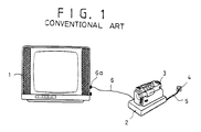
- a camcorder station apparatus as shown in Fig. 1, includes a station apparatus 2 with a function of transferring an output signal of the camcorder 3 to a TV set 1 upon a mode selection of the camcorder 3 for reproducing a tape recorded by the camcorder 3; an input terminal(not shown) of the station apparatus 2 for receiving power from the wall outlet 4 through a cable 5 for driving the station apparatus 2; and an input terminal 6a disposed at one side of the TV set for receiving the output signal from the output terminal(not shown) of the station apparatus through the cable 6.
- the camcorder is placed on an upper portion of the camcorder station apparatus 2, while the power and connecting terminals(not shown) disposed at the bottom of the camcorder 3 and the engaging portion(not shown) of the upper portion of the station apparatus 3 are electrically connected each other, so that it will be possible to watch the reproducing image through the TV set 1.
- the power supply for the station apparatus 2 is applied from the output terminal(not shown) of the station apparatus 2 through the wall outlet 4 and the cable 5.
- the power supply for the camcorder 3 is applied from the power terminal disposed at the upper portion of the station apparatus 2 through the power terminal at the bottom of the camcorder 3.
- the conventional camcorder needs an additionally separated station apparatus for reproducing a tape recorded by the camcorder 3, additionally requiring a connecting cable 6 that electrically connects the TV set 1 and the station apparatus 2 and the cable 5 for connecting the wall outlet 4 and the station apparatus 2 and thus reproducing the tape recorded by the camcorder 3 is inconvenient for the user.
- the disadvantages of the conventional station apparatus lie in that the range of its use is limited for only reproducing the tape recorded by the camcorder 3 despite its high price.
- the present invention includes an engaging portion disposed in a VCR for receiving and supporting a camcorder; a plurality of audio/video signal terminals disposed at the bottom of an engaging portion of the VCR for receiving an output signal of the camcorder; a plurality of power terminals disposed at the bottom of the engaging portion of the VCR for transferring power to the camcorder; and an audio/video cable for electrically connecting the output terminals with an input terminal of a TV set.
- Fig. 1 is a perspective view showing a conventional camcorder station apparatus in which a camcorder is engaged, and the station apparatus is electrically connected to the TV set.
- Fig. 2 is a perspective view showing a camcorder station apparatus disposed in a VCR according to the present invention.
- Fig. 3 is a partial cross-sectional view showing a camcorder disposed into an inserting groove of the VCR according to the present invention.
- Figs. 4A is a view showing the engaging portion of the bottom of the camcorder and Fig. 4B is a view showing the engaging portion of the VCR.
- Fig. 5 is a cross-sectional view showing a lid engaged at the engaging portion of the VCR according to an embodiment of the present invention.
- Fig. 6 is a cross-sectional view showing a lid engaged at the engaging portion of the VCR according to another embodiment of the present invention.
- FIG. 2 there is shown a structure of a camcorder station apparatus disposed in a VCR according to the present invention. As shown there, it includes an engaging portion 20 disposed in the VCR for receiving a camcorder 13.
- the engaging portion 20 has a plurality of power terminals 20a and connecting terminals 20b for electrically connecting with a plurality of power terminals(not shown) and connecting terminals(not shown) disposed at the bottom of a camcorder 13, respectively.
- the connecting terminals 20b are electrically connected with the camcorder 13 as well as with the terminals(not shown) for receiving an audio/video signal in order to dub the tape recorded by the camcorder 13 to the VHS tape of the VCR 12.
- the power supply is supplied to the power terminals 20a through the cable 14.
- the output signals of the camcorder 13 are supplied to the output terminals 20c of the VCR 12 through the connecting terminals 20b of the VCR 12 which are electrically in contact with the connecting terminals(not shown) disposed at the bottom of the camcorder 13.
- the output signals of the camcorder 13 transferred to the output terminals 20c of the VCR 12 are transferred to the input terminal 16a of the TV set 11 through the audio/video cable 15, so that the tape recorded by the camcorder 13 is reproduced on the TV set 11.
- FIG. 3 there is shown a camcorder 13 inserted into the inserting groove 21 of the engaging portion 20 of the VCR 12. As shown there, a plurality of power terminals(not shown) and connecting terminals(not shown) disposed at the bottom of the camcorder 13 are respectively in electrical contact with a plurality of power terminals 20a and connecting terminals 20b which are disposed at the bottom of the inserting groove 21.
- FIGs. 4A and 4B there are shown a plurality of power terminals 13a and connecting terminals 13b which are disposed at the bottom of the camcorder 13; an inserting groove 21 of an engaging portion 20 disposed at an upper portion of the VCR 12; and a plurality of power terminals 20a and connecting terminals 20b which are disposed at bottom of the inserting groove 21 of the VCR 12.
- the power terminals 20a and connecting terminals 20b have a plurality of spring grooves 20d and 20e.
- the upper portion of the spring grooves 20d and 20e is opened and at each of the bottoms thereof are disposed a plurality of holes(not shown) having smaller diameter than that of the spring grooves 20d and 20e.
- inside the spring grooves 20d and 20e are respectively disposed springs 18, on each of which a plurality of metallic balls 17 are disposed.
- the springs 18 and the metallic balls 17 are electrically connected with each other.
- the metallic balls 17 are tightly engaged at each of the upper portions of the springs 18.
- the bottom portion of the springs 18 are electrically connected with the output terminals 20C which are connected to the TV set 11 or the terminals(not shown) for receiving the audio/video signals from the outside for dubbing the tape recorded by the camcorder to the VHS tape.
- the inner surface of the spring grooves 20d and 20e, the metallic balls 17 and the springs 18 are completely electrically cut from each other, so that any electric leakage can be avoided therebetween.
- lids disposed for covering the engaging portion of the VCR 12.
- Fig. 5 it includes a plurality of hinge shafts 23a disposed at both sides of the inner upper portion of the inserting groove 21, respectively. At both hinge shafts 23a are disposed lids 22 covering the opening of the inserting groove 21. A spring 24 is disposed at the hinge shafts 23a to enable the lids 22 to cover the opening of the inserting groove 21 when the camcorder is disengaged therefrom by the recovering force of the spring 24. Here, both ends of the spring 24 are fixedly inserted into the VCR 12. As shown in Fig. 6,there is disposed a slide groove 26 having a predetermined width and length, which passes through the VCR 12. A lid 25 is slidably disposed into the slide groove 26. A handle 25a is disposed at one upper end portion of the lid 25. The groove 26 for receiving one end of the lid 25 is disposed at an inner upper portion of the inserting groove 21.
- the camcorder 13 is engaged at the engaging portion 20 disposed in the VCR 12.
- the power switch of the camcorder 13 When the power switch of the camcorder 13 is turned on, it transfers the output signals to the TV set 11 for reproducing the tape recorded by the camcorder 13.
- the tape recorded by the camcorder 13 can be dubbed to the VHS tape by switching the connecting terminals 20b to the audio/video terminal of the VCR 12.
- a manual or automatic switching method which can be installed at an upper portion of the inserting groove 21 of the VCR 12, so that upon engaging the camcorder 13 into the inserting groove 21 the tape recorded by the camcorder can be reproduced.
- an engaging portion disposed in the VCR is needed to engage the camcorder.
- the camcorder batteries can be charged by just placing the camcorder into the engaging portion of the VCR.
Landscapes
- Engineering & Computer Science (AREA)
- Multimedia (AREA)
- Signal Processing (AREA)
- Details Of Connecting Devices For Male And Female Coupling (AREA)
- Structure Of Receivers (AREA)
- Television Signal Processing For Recording (AREA)
Applications Claiming Priority (2)
| Application Number | Priority Date | Filing Date | Title |
|---|---|---|---|
| KR1019930018888A KR960005126B1 (ko) | 1993-09-17 | 1993-09-17 | 브이씨알 내장 캠코더 스테이션 장치 |
| KR1888893 | 1993-09-17 |
Publications (2)
| Publication Number | Publication Date |
|---|---|
| EP0644690A2 true EP0644690A2 (de) | 1995-03-22 |
| EP0644690A3 EP0644690A3 (de) | 1995-09-27 |
Family
ID=19363889
Family Applications (1)
| Application Number | Title | Priority Date | Filing Date |
|---|---|---|---|
| EP94402000A Ceased EP0644690A3 (de) | 1993-09-17 | 1994-09-08 | VCR mit Anschlussgerät für einen Camcorder. |
Country Status (3)
| Country | Link |
|---|---|
| EP (1) | EP0644690A3 (de) |
| JP (1) | JPH07177454A (de) |
| KR (1) | KR960005126B1 (de) |
Cited By (2)
| Publication number | Priority date | Publication date | Assignee | Title |
|---|---|---|---|---|
| EP0945009A4 (de) * | 1996-12-13 | 2002-05-02 | Disposable Video Camcorders Lt | Videoaufzeichnungsvorrichtung |
| US7062576B2 (en) | 1999-05-28 | 2006-06-13 | Nikon Corporation | Digital camera having imaging portion, first terminal, and second terminal for outputting signals based on image data in accordance with same data communication interface standard |
Family Cites Families (4)
| Publication number | Priority date | Publication date | Assignee | Title |
|---|---|---|---|---|
| JPS57127979A (en) * | 1981-01-30 | 1982-08-09 | Canon Inc | Video system |
| US4901160A (en) * | 1985-09-13 | 1990-02-13 | Takao Kinoshita | Electronic camera |
| US5341171A (en) * | 1991-08-23 | 1994-08-23 | Sony Corporation | Video camera apparatus with a connecting device for easy connection with electric apparatus |
| JPH06184973A (ja) * | 1992-12-14 | 1994-07-05 | New Oji Paper Co Ltd | リグニンを含有するパルプの生物処理方法 |
-
1993
- 1993-09-17 KR KR1019930018888A patent/KR960005126B1/ko not_active Expired - Fee Related
-
1994
- 1994-09-08 EP EP94402000A patent/EP0644690A3/de not_active Ceased
- 1994-09-16 JP JP6221583A patent/JPH07177454A/ja active Pending
Cited By (4)
| Publication number | Priority date | Publication date | Assignee | Title |
|---|---|---|---|---|
| EP0945009A4 (de) * | 1996-12-13 | 2002-05-02 | Disposable Video Camcorders Lt | Videoaufzeichnungsvorrichtung |
| US6957011B2 (en) | 1996-12-13 | 2005-10-18 | Disposable Video Camcorders Limited | Video recording apparatus |
| US7062576B2 (en) | 1999-05-28 | 2006-06-13 | Nikon Corporation | Digital camera having imaging portion, first terminal, and second terminal for outputting signals based on image data in accordance with same data communication interface standard |
| US7301561B2 (en) | 1999-05-28 | 2007-11-27 | Nikon Corporation | Digital image storage system that controls storage of digital images in folders of a storage medium |
Also Published As
| Publication number | Publication date |
|---|---|
| KR960005126B1 (ko) | 1996-04-20 |
| JPH07177454A (ja) | 1995-07-14 |
| EP0644690A3 (de) | 1995-09-27 |
| KR950009686A (ko) | 1995-04-24 |
Similar Documents
| Publication | Publication Date | Title |
|---|---|---|
| US4629962A (en) | Battery charging device | |
| US5132800A (en) | Video camera with an accessory adapter removably interposed between a battery package and a battery mount on the camera body | |
| EP0589571B1 (de) | Verbindungsgerät für Videobandrekorder mit eingebauter Kamera | |
| US5306956A (en) | Connecting system for supplying electrical power to a device in place of a battery along with the transmission of data signals from the device to monitoring apparatus, or supplying electrical power to a battery for the charging thereof | |
| JPH0325869B2 (de) | ||
| EP0644690A2 (de) | VCR mit Anschlussgerät für einen Camcorder | |
| US5598227A (en) | Television camera/recorder and a system for transmitting signals reproduced by the same | |
| KR930008191Y1 (ko) | 선택 조합 가능한 비디오 시스템 | |
| US20020008927A1 (en) | Connection apparatus for enabling an operative condition between a video cassette recorder and a camcorder | |
| JPH0117633B2 (de) | ||
| JPS633232Y2 (de) | ||
| JP2585813B2 (ja) | ビデオカメラのアクセサリー | |
| JP3000481U (ja) | 記録装置を内蔵したテレビ | |
| KR200159232Y1 (ko) | 캠코더의 신호 전달장치 | |
| JPS61284889A (ja) | ポ−タブル・ビデオテ−プレコ−ダ・システム | |
| JP3000352U (ja) | 記録装置を内蔵したテレビ | |
| JPS6133744Y2 (de) | ||
| KR960003007Y1 (ko) | 캠코더와 tv-vtr과의 연결장치 | |
| JP3000358U (ja) | 記録装置を内蔵したテレビ | |
| JP3000359U (ja) | 記録装置を内蔵したテレビ | |
| JP3000006U (ja) | 記録装置を内蔵したテレビ | |
| JPS6325801Y2 (de) | ||
| JPS6339194B2 (de) | ||
| EP0851688B1 (de) | Datensignalaufnahme- und -Wiedergabeverfahren und -System | |
| JPS6028052Y2 (ja) | 蓄電池電源装置 |
Legal Events
| Date | Code | Title | Description |
|---|---|---|---|
| PUAI | Public reference made under article 153(3) epc to a published international application that has entered the european phase |
Free format text: ORIGINAL CODE: 0009012 |
|
| AK | Designated contracting states |
Kind code of ref document: A2 Designated state(s): DE FR GB IT NL |
|
| PUAL | Search report despatched |
Free format text: ORIGINAL CODE: 0009013 |
|
| AK | Designated contracting states |
Kind code of ref document: A3 Designated state(s): DE FR GB IT NL |
|
| RAP1 | Party data changed (applicant data changed or rights of an application transferred) |
Owner name: LG ELECTRONICS INC. |
|
| 17P | Request for examination filed |
Effective date: 19960206 |
|
| GRAG | Despatch of communication of intention to grant |
Free format text: ORIGINAL CODE: EPIDOS AGRA |
|
| 17Q | First examination report despatched |
Effective date: 19971027 |
|
| STAA | Information on the status of an ep patent application or granted ep patent |
Free format text: STATUS: THE APPLICATION HAS BEEN REFUSED |
|
| 18R | Application refused |
Effective date: 19980614 |