EP0642830A1 - Closure with an array of pierceable sites - Google Patents
Closure with an array of pierceable sites Download PDFInfo
- Publication number
- EP0642830A1 EP0642830A1 EP94113449A EP94113449A EP0642830A1 EP 0642830 A1 EP0642830 A1 EP 0642830A1 EP 94113449 A EP94113449 A EP 94113449A EP 94113449 A EP94113449 A EP 94113449A EP 0642830 A1 EP0642830 A1 EP 0642830A1
- Authority
- EP
- European Patent Office
- Prior art keywords
- closure
- pipetting
- upper wall
- closure according
- pipetting needle
- Prior art date
- Legal status (The legal status is an assumption and is not a legal conclusion. Google has not performed a legal analysis and makes no representation as to the accuracy of the status listed.)
- Ceased
Links
Images


Classifications
-
- B—PERFORMING OPERATIONS; TRANSPORTING
- B01—PHYSICAL OR CHEMICAL PROCESSES OR APPARATUS IN GENERAL
- B01L—CHEMICAL OR PHYSICAL LABORATORY APPARATUS FOR GENERAL USE
- B01L3/00—Containers or dishes for laboratory use, e.g. laboratory glassware; Droppers
- B01L3/50—Containers for the purpose of retaining a material to be analysed, e.g. test tubes
- B01L3/508—Containers for the purpose of retaining a material to be analysed, e.g. test tubes rigid containers not provided for above
- B01L3/5082—Test tubes per se
- B01L3/50825—Closing or opening means, corks, bungs
Definitions
- the invention relates to a closure for a reagent container, which can be used in an analytical device in which an automatic pipetting device for transferring small amounts of reagent from the reagent container to the reaction cuvettes is used, the pipetting device having a pipetting needle that is automatically guided by a transport device and has a free open end in lies in a plane which forms an acute angle with the longitudinal axis of the pipetting needle, which closure is a part molded in one piece from a plastic, and has a cylindrical side wall and an annular top wall adjoining the side wall.
- the invention is therefore based on the object of providing a closure of the type specified at the beginning, with which the disadvantages mentioned above can be eliminated.
- this object is achieved with a closure, which is characterized in that the central region of the upper wall has an arrangement of depressions of the same size which lie next to one another, adjacent depressions being delimited from one another by a partition wall in each case, which is at their free upper end forms a sharp edge and the bottom of each recess can be pierced with the pipetting needle of the pipetting device.
- the closure according to the invention makes it possible to automate the treatment of the reagent container in the analysis system, i.e. relieve the laboratory staff of the manual work previously required, and at the same time increase the reliability of this treatment.
- the closure according to the invention is preferably a screw closure. This ensures a good seal of the reagent container in a simple manner.
- the outer surface of the partition wall forms a second acute angle with a straight line perpendicular to the floor. It is thereby achieved that the partition wall pushes the tip of the pipetting needle to the center of the depression if the transport device of the pipetting needle does not lead it exactly to the center of a depression.
- closure cap 1 which can be seen in FIGS. 1 and 3 is, as usual, applied tightly to the neck 2 of a container 3 by means of a threaded connection.
- the cap 1 consists essentially of a cylindrical wall 4 which on the upper end face by a Basically flat plate 5 is completed. On the outside on the cylindrical wall 4, structures 6 can be seen to increase the grip.
- a sealing tube 9 which is adapted to the inner diameter of the container neck 2, is formed from the upper cover plate 5 and projects into the container neck 2.
- recesses 11 which define possible puncture points of a pipetting needle 13 in their base or bottom 12.
- the cap is preferably molded in one piece from a suitable plastic, e.g. made of polyethylene, e.g. LDPE (low density polyethylene) or HDPE (high density polyethylene).
- a suitable plastic e.g. made of polyethylene, e.g. LDPE (low density polyethylene) or HDPE (high density polyethylene).
- the base areas or bottoms 12 of the depressions 11, which have the wall thickness to be penetrated by a pipetting needle 13 and reduced compared to the wall thickness of the cover plate 5, are matched in terms of their surface area to the pipette needle cross section to be used and are advantageously circular.
- the depressions 11 are advantageously frustoconical, the smaller circular area forming the base area or the base 12 or a puncture point.
- Recesses 11 are arranged in the central area of the end plate 5 and form a puncture zone 16 in such a way that the highest possible density, i.e. results in the highest possible number of puncture points per unit area, the wall parts 15 remaining between the base areas or floors 12, which stabilize the entire puncture zone 16, being of sufficient quality.
- the depressions 11 are advantageously arranged in rows offset from one another in such a way that there is essentially a hexagonal outer contour of the puncture zone 16.
- the depressions 11 are spaced apart from one another in such a way that, due to the intersection of the conical outer surfaces 18 of the depressions 11, sharp cutting edges 17 form, which are viewed from above (FIG. 5) in a hexagonal configuration, a respective one Surrounding floor 12, and seen from the side, manifesting a hyperbolic curve (FIGS. 4 and 6).
- the resulting roof-shaped boundary walls 15 of the bottom or puncture surfaces 12 provide reliable positive guidance of a pipetting needle 13 positioned relatively roughly above the puncture zone 16 to a corresponding puncture site.
- the tip angle ⁇ of the pipetting needle 13 is approximately 30 degrees.
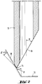
- the tip 14 of the pipetting needle 13 is rounded (FIG. 2).
- the angle of inclination ⁇ of the conical outer surface 18 (with respect to the longitudinal axis of the pipetting needle) of the depressions 11 is adapted to the tip angle ⁇ of the pipetting needle 13 and is preferably of approximately the same size.
- the angle of inclination ⁇ is preferably between 20 and 40 degrees.
- the alignment and centering forces on the pipetting needle 13 and. can act on the closure cap 1 are indicated schematically in Fig. 6 by means of arrows. If, for example, a (Pf1) pipetting needle 13 guided against the puncture zone 16 (indicated by dash-dotted lines in FIG. 5) strikes a boundary wall 15, then on the one hand the pipetting needle 13 can be self-elasticized (Pf2) and on the other hand the closure cap 1 together with the container 3 ( Pf3), due to a movable holder of the container 3 moving in a horizontal plane within certain limits, in such a way that the pipetting needle 13 ultimately reaches the base 12 and pierces it.
- Pf1 pipetting needle 13 guided against the puncture zone 16 (indicated by dash-dotted lines in FIG. 5) strikes a boundary wall 15, then on the one hand the pipetting needle 13 can be self-elasticized (Pf2) and on the other hand the closure cap 1 together with the container 3 ( Pf3), due to a movable holder
Landscapes
- Health & Medical Sciences (AREA)
- Chemical & Material Sciences (AREA)
- Analytical Chemistry (AREA)
- General Health & Medical Sciences (AREA)
- Hematology (AREA)
- Clinical Laboratory Science (AREA)
- Chemical Kinetics & Catalysis (AREA)
- Automatic Analysis And Handling Materials Therefor (AREA)
- Devices For Use In Laboratory Experiments (AREA)
- Sampling And Sample Adjustment (AREA)
- Closures For Containers (AREA)
- Investigating Or Analysing Biological Materials (AREA)
Abstract
Description
Die Erfindung betrifft einen Verschluss für einen Reagenzbehälter, der in einem Analysengerät verwendbar ist, in dem eine automatische Pipettiervorrichtung zur Uebertragung von kleinen Reagenzmengen vom Reagenzbehälter zu Reaktionsküvetten verwendet wird, wobei die Pipettiervorrichtung eine durch eine Transportvorrichtung automatisch geführte Pipettiernadel hat, deren freies offenes Ende in einer Ebene liegt, die mit der Längsachse der Pipettiernadel einen spitzen Winkel bildet, welcher Verschluss ein aus einem Kunststoff in einem Stück geformten Teil ist, und eine zylindrische Seitenwand und eine ringförmige an der Seitenwand angrenzende obere Wand hat.The invention relates to a closure for a reagent container, which can be used in an analytical device in which an automatic pipetting device for transferring small amounts of reagent from the reagent container to the reaction cuvettes is used, the pipetting device having a pipetting needle that is automatically guided by a transport device and has a free open end in lies in a plane which forms an acute angle with the longitudinal axis of the pipetting needle, which closure is a part molded in one piece from a plastic, and has a cylindrical side wall and an annular top wall adjoining the side wall.
Bei bisher bekannten Analysensystemen, z.B. im Gebiet der klinischen chemischen Analyse von biologischen Proben, werden offene Reagenzbehälter verwendet. Daraus wird jeweils mittels einer automatischen Pipettiervorrichtung eine kleine Menge eines flüssigen Reagenz entnommen und einer Reaktionsküvette zugeführt. Für jeden Pipettiervorgang führt ein elektromechanisch angetriebener Arm die Pipettiernadel der Pipettiervorrichtung zu einem Reagenzbehälter, führt ihn dort in den Reagenzbehälter zur Entnahme eines Reagenzvolumens ein, nimmt die Pipettiernadel danach aus dem Reagenzbehälter heraus und führt sie zu dem Reaktionsgefäss, zu dem das Reagenzvolumen zugeführt werden soll. Der Inhalt eines üblichen Reagenzbehälters reicht für eine relativ grosse Zahl (in der Grössenordnung von 20 bis 2000) solcher Pipettiervorgänge aus.In previously known analysis systems, e.g. in the field of clinical chemical analysis of biological samples, open reagent containers are used. From this, a small amount of a liquid reagent is withdrawn by means of an automatic pipetting device and fed to a reaction cuvette. For each pipetting process, an electromechanically driven arm leads the pipetting needle of the pipetting device to a reagent container, introduces it there into the reagent container for taking out a reagent volume, then takes the pipetting needle out of the reagent container and leads it to the reaction vessel to which the reagent volume is to be supplied . The content of a conventional reagent container is sufficient for a relatively large number (of the order of 20 to 2000) of such pipetting processes.
Die Benutzung offener Reagenzbehälter hat folgende Nachteile:
- Das Laborpersonal muss jeden neuen Reagenzbehälter aus seiner Verpackung entnehmen, seinen Verschluss entfernen und den offenen Reagenzbehälter im Analysensystem anstelle eines leeren Reagenzbehälters einsetzen. In einem und demselben Analysensystem werden ausserdem oft viele verschiedene Reagenzien zu verschiedenen Zeitpunkten benötigt. Die Benutzung offener Reagenzbehälter erfordert daher vom Laborpersonal einen erheblichen Arbeitsaufwand.
- Bei Benutzung offener Reagenzbehälter in Räumen mit relativ trockener Luft geht ein Teil der Reagenzlösung durch Verdunstung verloren und dadurch tritt mit der Zeit eine Erhöhung der Reagenzkonzentration ein. Bei Benutzung offener Reagenzbehälter in Räumen mit relativ feuchter Luft oder durch Kondenswasserbildung bei Verwendung gekühlter Reagenzien nimmt hingegen das Volumen der Reagenzlösung zu und dadurch tritt mit der Zeit eine Verringerung der Reagenzkonzentration ein. Bei Benutzung offener Reagenzbehälter findet ausserdem ein Gasaustausch mit der Umgebungsluft statt, der eine Alterung bzw. Aenderung des Reagenz verursacht. Alle soeben erwähnten Aenderungen des Reagenz und insbesondere der Reagenzkonzentration verursachen eine Verringerung der Genauigkeit der durchgeführten Analysen. Um dies wenigstens teilweise zu vermeiden, wurden bisher relativ aufwendige Verpackungen des ganzen Reagenzbehälters verwendet.
- Laboratory personnel must remove each new reagent container from its packaging, remove its cap and insert the open reagent container in the analysis system instead of an empty reagent container. In one and the same analysis system, many different reagents are often required at different times. The use of open reagent containers therefore requires a lot of work from laboratory personnel.
- If open reagent containers are used in rooms with relatively dry air, some of the reagent solution is lost due to evaporation and, as a result, the reagent concentration increases over time. When using open reagent containers in rooms with relatively humid air or due to the formation of condensation when using cooled reagents, the volume of the reagent solution increases and, as a result, the reagent concentration decreases over time. When using open reagent containers, there is also a gas exchange with the ambient air, which causes the reagent to age or change. All changes in the reagent and in particular the reagent concentration just mentioned cause a reduction in the accuracy of the analyzes carried out. In order to avoid this at least in part, relatively complex packaging of the entire reagent container has hitherto been used.
Diese Nachteile offener Reagenzbehälter werden mit dem Reagenzbehälter gemäss der EP-A- 0 192 968 A2 beseitigt, der mit einem durchstechbaren Verschluss versehen ist. Der durchstechbare Teil dieses Verschlusses ist eine Membran im mittleren Bereich der oberen Wand des Verschlusses. Dieser bekannte Verschluss hat folgende Nachteile:
Bei der Durchführung einer Vielzahl von Pipettiervorgängen (z.B. 200 bis 1000) durch dieselbe Membran wird diese in zunehmenden Masse durch die Pipettiernadel beschädigt, weil diese die Membran an dicht nebeneinander liegenden Stellen durchsticht und mit der Zeit kleine Fragmente der Membran ausschneidet, die in das darunter liegende Reagenz fallen. Dadurch entsteht mit der Zeit eine immer grössere Oeffnung in der Mitte der Membran, und dies hat zur Folge, dass die erforderliche Abdichtung des Reagenzbehälters nicht mehr gewährleistet ist. Ausserdem können die im Reagenz schwebenden Fragmente der Membran eine Verstopfung der Pipettiernadel verursachen und dadurch den Betrieb des Analysengeräts beeinträchtigen.These disadvantages of open reagent containers are eliminated with the reagent container according to EP-A-0 192 968 A2, which is provided with a pierceable closure. The pierceable part of this closure is a membrane in the central area of the top wall of the closure. This known closure has the following disadvantages:
When carrying out a large number of pipetting processes (e.g. 200 to 1000) through the same membrane, this is increasingly damaged by the pipetting needle because it pierces the membrane in closely adjacent locations and cuts out small fragments of the membrane over time, which cut into the one below lying reagent fall. Over time, this creates an ever larger opening in the middle of the membrane, and the result is that the required sealing of the reagent container is no longer guaranteed. In addition, the fragments of the The membrane may clog the pipetting needle and thereby impair the operation of the analyzer.
Die soeben erwähnten Nachteile werden mit dem Verschluss für Reagenzbehälter gemäss der EP-A 0 504 697 A1 gelöst, der eine einzige durchstechbare Stelle in der Mitte der oberen Wand des Verschlusses aufweist, durch die die Pipettiernadel bei allen Pipettiervorgängen eingeführt wird. Die Verwendung dieses Verschlusses setzt daher voraus, dass die Transporteinrichtung der Pipettiernadel diese sehr genau in bezug auf die durchstechbare Stelle des Verschlusses positionieren kann. Abgesehen davon, dass eine so präzise Positionierung der Pipettiernadel einen nicht unerheblichen Aufwand erfordert, ist sie in manchen Anwendungen aus anderen Gründen kaum erreichbar. Z.B. wenn der Reagenzbehälter vor dem Pipettiervorgang einen automatischen Schüttelbewegung unterzogen wird, an deren Ende die Position des Reagenzbehälters und des entsprechenden Verschlusses nicht mehr so genau definiert ist, als wenn mit einem stets ruhenden Reagenzbehälters gearbeitet wird.The disadvantages just mentioned are solved with the closure for reagent containers according to EP-A 0 504 697 A1, which has a single pierceable point in the middle of the upper wall of the closure, through which the pipetting needle is inserted during all pipetting processes. The use of this closure therefore presupposes that the transport device of the pipetting needle can position it very precisely with respect to the pierceable point of the closure. Apart from the fact that such a precise positioning of the pipetting needle requires a considerable amount of effort, it can hardly be reached in other applications for other reasons. E.g. if the reagent container is subjected to an automatic shaking movement before the pipetting process, at the end of which the position of the reagent container and the corresponding closure is no longer defined as precisely as when working with a reagent container which is always stationary.
Der Erfindung liegt daher die Aufgabe zugrunde, einen Verschluss der eingangs angegebenen Art zur Verfügung zu stellen, mit dem die oben erwähnten Nachteile behoben werden können.The invention is therefore based on the object of providing a closure of the type specified at the beginning, with which the disadvantages mentioned above can be eliminated.
Erfindungsgemäss wird diese Aufgabe mit einem Verschluss gelöst, welches dadurch gekennzeichnet ist, dass der mittlere Bereich der obere Wand eine Anordnung von gleicher grossen Vertiefungen hat, die nebeneinander liegen, wobei benachbarte Vertiefungen voneinander durch je eine Trennwand abgegrenzt sind, die an ihrem freien oberen Ende eine scharfe Kante bildet und der Boden jeder Vertiefung mit der Pipettiernadel der Pipettiervorrichtung durchstechbar ist.According to the invention, this object is achieved with a closure, which is characterized in that the central region of the upper wall has an arrangement of depressions of the same size which lie next to one another, adjacent depressions being delimited from one another by a partition wall in each case, which is at their free upper end forms a sharp edge and the bottom of each recess can be pierced with the pipetting needle of the pipetting device.
Die wesentlichen Vorteile des erfindungsgemässen Verschlusses sind wie folgt:
- Zur Durchführung der Pipettierungen von Reagenz vom Reagenzbehälter zu den Reaktionsküvetten kann die Pipettiernadel durch den Verschluss in den Reagenzbehälter eingeführt werden. Für die Benutzung des Reagenzbehälters im Analysensystem ist es daher nicht erforderlich, den Verschluss zu entfernen.
- Bei jedem Pipettiervorgang wird die Pipettiernadel durch den Boden einer der Vertiefungen im mittleren Bereich der oberen Wand des Verschlusses eingeführt. Bei welcher Vertiefung der Boden mit der Pipettiernadel durchgestochen wird ist unwichtig. Bei vielen Pipettiervorgängen durch denselben Verschluss kann es vorkommen, dass Pipettiernadel durch eine Vertiefung eingeführt wird, deren Boden in einem früheren Pipettiervorgang bereits durchgestochenen wurde. Auch dies ist im Rahmen der Erfindung zulässig. Die Benutzung des erfindungsgemässen Verschlusses ermöglicht daher, die Anforderungen an der Genauigkeit der automatischen Positionierung der Pipettiernadel zu reduzieren. Durch den Aufbau des erfindungsgemässen Verschlusses wird ausserdem sichergestellt, dass auch bei einer grossen Zahl von Pipettiervorgängen (z.B. 200 bis 1000) durch denselben Verschluss keine Beschädigung des Verschlusses und keine dadurch verursachte Verstopfung der Pipettiernadel (durch Fragmente des Verschlusses) eintreten kann. Dies ist hingegen z.B. bei Verwendung eines einfachen Stopfens oder eines Verschlusses mit einer durchstechbaren Membran der Fall.
- Wenn man von kleinen Stichen im durchgestochenen Boden der für die Pipettiervorgängen verwendeten Vertiefungen absieht, bleibt der mit dem erfindungsgemässen Verschluss versehenen Reagenzbehälter während seiner ganzen Benutzungsdauer im Analysensystems praktisch geschlossen. Ein Verdunsten der Reagenzlösung, einen Gasaustausch mit der Umgebungsluft und dadurch eine vorzeitige Alterung des Reagenz werden dadurch weitgehend verhindert. Die Abmessungen der Vertiefungen und deren Böden werden so gewählt, dass beim Eindringen und Herausziehen der Pipettiernadel diese abgestreift wird, was eine Kontamination von verschiedenen Reagenzien grösstenteils verhindert.
- To carry out the pipetting of reagent from the reagent container to the reaction cuvettes, the pipetting needle can be inserted into the reagent container through the closure. It is therefore not necessary to remove the cap when using the reagent container in the analysis system.
- During each pipetting process, the pipetting needle is inserted through the bottom of one of the depressions in the middle area of the upper wall of the closure. The depth at which the bottom is pierced with the pipetting needle is unimportant. In many pipetting processes through the same closure, it may happen that the pipetting needle is inserted through a depression, the bottom of which has already been pierced in an earlier pipetting process. This is also permissible within the scope of the invention. The use of the closure according to the invention therefore makes it possible to reduce the requirements for the accuracy of the automatic positioning of the pipetting needle. The construction of the closure according to the invention also ensures that even with a large number of pipetting processes (for example 200 to 1000) no damage to the closure and no clogging of the pipetting needle caused by fragments of the closure can occur as a result of the same closure. However, this is the case, for example, when using a simple stopper or a closure with a pierceable membrane.
- Apart from small stitches in the perforated bottom of the wells used for the pipetting processes, the reagent container provided with the closure according to the invention remains practically closed during its entire period of use in the analysis system. This largely prevents evaporation of the reagent solution, gas exchange with the ambient air and premature aging of the reagent. The dimensions of the wells and their bottoms are selected so that when the pipette needle penetrates and is pulled out, it is stripped off, which largely prevents contamination of various reagents.
Durch die soeben erwähnten Vorteile ermöglicht der erfindungsgemässe Verschluss, die Behandlung des Reagenzbehälters im Analysensystem zu automatisieren, d.h. das Laborpersonal von der bisher dafür erforderlichen manuellen Tätigkeit zu entlasten, und gleichzeitig die Zuverlässigkeit dieser Behandlung zu erhöhen.Due to the advantages just mentioned, the closure according to the invention makes it possible to automate the treatment of the reagent container in the analysis system, i.e. relieve the laboratory staff of the manual work previously required, and at the same time increase the reliability of this treatment.
Der erfindungsgemässe Verschluss ist vorzugsweise ein Schraubverschluss. Dadurch wird auf einfache Weise eine gute Abdichtung des Reagenzbehälters sichergestellt.The closure according to the invention is preferably a screw closure. This ensures a good seal of the reagent container in a simple manner.
In einer bevorzugten Ausführungsform des erfindungsgemässen Verschlusses bildet die Aussenfläche der Trennwand mit einer zum Boden senkrechten Gerade einen zweiten spitzen Winkel. Dadurch wird erreicht, dass die Trenwand die Spitze der Pipettiernadel zur Mitte der Vertiefung schiebt, wenn die Transportvorrichtung der Pipettiernadel diese nicht genau zur Mitte einer Vertiefung führt.In a preferred embodiment of the closure according to the invention, the outer surface of the partition wall forms a second acute angle with a straight line perpendicular to the floor. It is thereby achieved that the partition wall pushes the tip of the pipetting needle to the center of the depression if the transport device of the pipetting needle does not lead it exactly to the center of a depression.
Ein Ausführungsbeispiel der Erfindung wird im folgenden anhand der beiliegenden Zeichnungen beschrieben. Es zeigen:
- Fig. 1
- eine perspektivische Darstellung eines mit einem erfindungsgemässen Verschlusses versehenen Behälters mit einer darüber positionierten Pipettiernadel,
- Fig. 1a
- den Spitzenbereich einer bevorzugten Ausführungsform der Pipettiernadel 13 in Fig. 1 vergrössert und geschnitten,
- Fig. 2
- den Spitzenbereich einer zweiten Ausführungsform der Pipettiernadel 13 in Fig. 1 vergrössert und geschnitten,
- Fig. 3
- einen vergrösserten Teilschnitt durch einen, einen erfindungsgemässen Verschlusses aufweisenden Behälter ,
- Fig. 4
- einen vergrösserten Teilausschnitt des Bodens eines erfindungsgemässen Verschlusses gemäss Fig. 1,
- Fig. 5
- eine Draufsicht auf den zentralen Bereich des Bodens eines erfindungsgemässen Verschlusses gemäss Fig. 1,
- Fig. 6
- einen Schnitt gemäss der Linie VI-VI in Fig. 5 mit einer durchgestochene Pipettiernadel wobei die Bewegungs- und Kraftkomponenten welche zur Führung bzw. Zentrierung der Pipettiernadel dienen schematisch angedeutet sind.
- Fig. 1
- 2 shows a perspective illustration of a container provided with a closure according to the invention with a pipetting needle positioned above it,
- Fig. 1a
- 1 enlarged and cut the tip area of a preferred embodiment of the
pipetting needle 13 in FIG. 1, - Fig. 2
- 1 enlarged and cut the tip area of a second embodiment of the
pipetting needle 13 in FIG. 1, - Fig. 3
- 2 shows an enlarged partial section through a container having a closure according to the invention,
- Fig. 4
- 2 shows an enlarged partial section of the bottom of a closure according to the invention according to FIG. 1,
- Fig. 5
- 2 shows a plan view of the central area of the bottom of a closure according to the invention according to FIG. 1,
- Fig. 6
- a section along the line VI-VI in Fig. 5 with a pierced pipetting needle, the movement and force components which serve to guide or center the pipetting needle are indicated schematically.
Die in den Figuren 1 und 3 erkennnbare erfindungsgemässe Verschlusskappe 1 ist wie üblich auf den Hals 2 eines Behälters 3 mittels einer Gewindeverbindung dicht aufgebracht.The closure cap 1 according to the invention which can be seen in FIGS. 1 and 3 is, as usual, applied tightly to the
Die Verschlusskappe 1 besteht im wesentlichen aus einer zylindrischen Wand 4 welche an der oberen Stirnseite durch eine im Grunde ebene Platte 5 abgeschlossen ist. Aussenseitig auf der zylindrischen Wand 4 sind Strukturen 6 zur Erhöhung der Griffigkeit erkennbar. An der Innenseite der zylindrischen Wand 4 ist ein Innengewinde 7, korrespondierend mit dem Aussengewinde 8 des Behälterhalses 2 eingeformt. Koaxial zur zylindrischen Wand 4 ist ein an den Innendurchmesser des Behälterhalses 2 angepasster Dichttubus 9 von der oberen Deckplatte 5, in den Behälterhals 2 hineinragend angeformt. In der dem Behälterinnenraum abgewandten Seite der Deckplatte 5 sind Vertiefungen 11 eingelassen welche in ihrem Grund bzw. Boden 12 mögliche Einstichstellen einer Pipettiernadel 13 definieren.The cap 1 consists essentially of a
Die Verschlusskappe wird vorzugsweise in einem Stück aus einem geeignetem Kunststoffgeformt, z.B. aus Polyethylen, z.B. LDPE (low density polyethylene) oder HDPE (high density polyethylene).The cap is preferably molded in one piece from a suitable plastic, e.g. made of polyethylene, e.g. LDPE (low density polyethylene) or HDPE (high density polyethylene).
Die Grundflächen bzw. Böden 12 der Vertiefungen 11 welche die von einer Pipettiernadel 13 zu durchdringende, gegenüber der Wandstärke der Deckplatte 5 reduzierte Wandstärke aufweisen, sind bezüglich ihrer Flächenausdehnung auf den zur Verwendung gelangenden Pipettiernadelquerschnitt abgestimmt und in vorteilhafter Weise kreisförmig ausgebildet.The base areas or
Vorteilhafter Weise sind die Vertiefungen 11 kegelstumpfförmig, wobei die kleinere Kreisfläche die Grundfläche bzw. den Boden 12 bzw. eine Durchstichsstelle bildet. Eine Vielzahl von Grundflächen 12 resp. Vertiefungen 11 sind im zentralen Bereich der Stirnplatte 5 angeordnet und bilden eine Einstichzone 16, derart, dass sich eine möglichst hohe Dichte, d.h. eine möglichst hohe Zahl von Einstichstellen pro Flächeneinheit ergibt, wobei die zwischen den Grundflächen bzw. Böden 12 verbleibenden Wandungsteile 15, welche die gesamte Einstichzone 16 stabilisieren, in ausreichender Qualität vorhanden sind.The
Vorteilhafter Weise sind die Vertiefungen 11 in derart gegeneinander versetzten Reihen angeordnet, dass sich im wesentlichen eine hexagonale Aussenkontur der Einstichzone 16 ergibt. In einer besonders bevorzugten Ausführung sind die Vertiefungen 11 voneinander derart beabstandet, dass sich aufgrund der Verschneidung der kegelförmigen Mantelflächen 18 der Vertiefungen 11 scharfe Schneiden 17 ausbilden, welche sich von oben betrachtet (Fig. 5) in einer hexagonalen Konfiguration, einen jeweiligen Boden 12 umgebend, und von der Seite betrachtet hyperbelartig geschwungen (Fig. 4 und 6) manifestieren.The
Durch die daraus resultierenden dachförmigen Begrenzungswände 15 der Boden- bzw. Einstichflächen 12 ist eine zuverlässige Zwangsführung einer relativ grob über der Einstichzone 16 positionierten Pipettiernadel 13 zu einer entsprechenden Einstichstelle gegeben.The resulting roof-shaped
Der Spitzenwinkel ϑ der Pipettiernadel 13 beträgt in etwa 30 Grad. Um die zu durchstechende Wandung des Bodens 12 bzw. die Begrenzungswände 15 nicht zu zerschneiden ist die Spitze 14 der Pipettiernadel 13 abgerundet (Fig. 2). Der Neigungswinkel φ der Kegelmantelfläche 18 (in Bezug auf die Pipettiernadellängsachse) der Vertiefungen 11 ist an den Spitzenwinkel ϑ der Pipettiernadel 13 angepasst und weist vorzugsweise in etwa die gleiche Grösse auf. Der Neigungswinkel φ liegt vorzugsweise zwischen 20 und 40 Grad.The tip angle ϑ of the
Die Ausricht- und Zentrierkräfte welche auf die Pipettiernadel 13 resp. auf die Verschlusskappe 1 wirken können sind in Fig. 6 schematisch mittels Pfeile angedeutet. Trifft beispielsweise eine gegen die Einstichzone 16 geführte (Pf1) Pipettiernadel 13 (in Fig. 5 strichpunktiert angedeutet) auf eine Begrenzungswand 15, so kann zum einen die Pipettiernadel 13 durch Eigenelastizität (Pf2) bzw. zum anderen auch die Verschlusskappe 1 nebst Behälter 3 (Pf3), bedingt durch eine in gewissen Grenzen bewegliche Halterung des Behälters 3 in einer horizontalen Ebene nachgeben, derart, dass letztendlich die Pipettiernadel 13 zum Boden 12 gelangt und diesen durchsticht.The alignment and centering forces on the
Claims (9)
welcher Verschluss (1) ein aus einem Kunststoff in einem Stück geformten Teil ist, und eine zylindrische Seitenwand (4) und eine an der Seitenwand angrenzende obere Wand (5) hat,
dadurch gekennzeichnet, dass
der mittlere Bereich der obere Wand (5) eine Einstichzone (16) hat, die durch eine Anordnung von gleich grossen Vertiefungen (11) gebildet ist, die nebeneinander liegen, wobei benachbarte Vertiefungen (11) voneinander durch je eine Trennwand (15) abgegrenzt sind, die an ihrem freien oberen Ende eine scharfe Kante (17) bildet
und
der Boden (12) jeder Vertiefung (11) mit der automatisch geführten Pipettiernadel (13) der Pipettiervorrichtung durchstechbar ist.Closure (1) for a reagent container (3), which can be used in an analytical device in which an automatic pipetting device for transferring small amounts of reagent from the reagent container (3) to reaction cuvettes is used, the pipetting device being a pipetting needle (13 ), whose free open end (19) lies in a plane that forms a first acute angle (ϑ) with the longitudinal axis of the pipetting needle,
which closure (1) is a part molded in one piece from a plastic and has a cylindrical side wall (4) and an upper wall (5) adjoining the side wall,
characterized in that
the middle region of the upper wall (5) has a puncture zone (16) which is formed by an arrangement of equally large depressions (11) which lie next to one another, adjacent depressions (11) being delimited from each other by a partition wall (15) which forms a sharp edge (17) at its free upper end
and
the bottom (12) of each recess (11) can be pierced with the automatically guided pipetting needle (13) of the pipetting device.
Applications Claiming Priority (2)
| Application Number | Priority Date | Filing Date | Title |
|---|---|---|---|
| CH2719/93 | 1993-09-10 | ||
| CH271993 | 1993-09-10 |
Publications (1)
| Publication Number | Publication Date |
|---|---|
| EP0642830A1 true EP0642830A1 (en) | 1995-03-15 |
Family
ID=4240065
Family Applications (1)
| Application Number | Title | Priority Date | Filing Date |
|---|---|---|---|
| EP94113449A Ceased EP0642830A1 (en) | 1993-09-10 | 1994-08-29 | Closure with an array of pierceable sites |
Country Status (3)
| Country | Link |
|---|---|
| EP (1) | EP0642830A1 (en) |
| JP (1) | JPH07191040A (en) |
| CA (1) | CA2130129A1 (en) |
Cited By (5)
| Publication number | Priority date | Publication date | Assignee | Title |
|---|---|---|---|---|
| EP1284160A2 (en) * | 2001-08-17 | 2003-02-19 | Becton, Dickinson and Company | Liquid specimen collection system |
| WO2003065047A1 (en) * | 2002-02-01 | 2003-08-07 | Stago Instruments | Device for automatic analysis of a liquid sample |
| ITPD20080334A1 (en) * | 2008-11-14 | 2010-05-15 | Holos Sro | ANTI-TAMPER CLOSING CAP FOR TUBES |
| CN103071556A (en) * | 2012-06-15 | 2013-05-01 | 郑州安图绿科生物工程有限公司 | Reagent bottle and holder for medical analyzer |
| CN112816681A (en) * | 2020-06-19 | 2021-05-18 | 上海快灵生物科技有限公司 | Biochemical test paper tube |
Families Citing this family (7)
| Publication number | Priority date | Publication date | Assignee | Title |
|---|---|---|---|---|
| AU2005218498A1 (en) * | 2004-03-02 | 2005-09-15 | Dako Denmark A/S | Reagent delivery system, dispensing device and container for a biological staining apparatus |
| JP2006001600A (en) * | 2004-06-18 | 2006-01-05 | Toppan Printing Co Ltd | Plastic cap with temper-resistant function |
| JP5545233B2 (en) * | 2011-01-31 | 2014-07-09 | コニカミノルタ株式会社 | Inspection system |
| JP6513926B2 (en) * | 2014-10-20 | 2019-05-15 | アークレイ株式会社 | Analytical tool, analytical device, analytical system including them, and method for drilling sheet-like member covering opening of analytical tool |
| EP3236269B1 (en) * | 2014-12-18 | 2024-02-07 | Hitachi High-Tech Corporation | Sampling nozzle, automated analyzer using the same, and sampling nozzle manufacturing method |
| BR102017015998A2 (en) * | 2017-07-26 | 2019-03-26 | Sociedade Beneficente Israelita Brasileira Hospital Albert Einstein | SEALER FILM AND PIPETING METHOD USING A SEALER FILM |
| EP4051433A4 (en) * | 2019-10-28 | 2022-12-21 | Siemens Healthcare Diagnostics, Inc. | VIBRATING PIPETTE TIPS AND METHODS TO AVOID PIPETTE TIP STICKING FRICTION |
Citations (5)
| Publication number | Priority date | Publication date | Assignee | Title |
|---|---|---|---|---|
| FR1202433A (en) * | 1958-07-16 | 1960-01-11 | Improvements made to means of stoppering containers, in particular those intended for pharmaceutical products or similar products | |
| US3653528A (en) * | 1970-03-03 | 1972-04-04 | West Co | Stopper for medicament flasks |
| EP0019264A2 (en) * | 1979-05-18 | 1980-11-26 | Terumo Corporation | Plastic container for medical liquid |
| WO1984000530A1 (en) * | 1982-07-21 | 1984-02-16 | Schubert & Co A S | A closure for a container, such as an infusion bottle |
| EP0504697A1 (en) * | 1991-03-19 | 1992-09-23 | F. Hoffmann-La Roche Ag | Reagent container closure |
Family Cites Families (6)
| Publication number | Priority date | Publication date | Assignee | Title |
|---|---|---|---|---|
| JPS56137072U (en) * | 1980-03-17 | 1981-10-17 | ||
| US4539855A (en) * | 1984-05-03 | 1985-09-10 | Eastman Kodak Company | Apparatus for transferring liquid out of a capped container, and analyzer utilizing same |
| DE3664005D1 (en) * | 1985-10-09 | 1989-07-20 | Kontron Holding Ag | Liquid-withdrawing device |
| JPS62235570A (en) * | 1986-04-05 | 1987-10-15 | Japan Spectroscopic Co | Specimen sampling apparatus |
| JPH0350451Y2 (en) * | 1987-07-16 | 1991-10-28 | ||
| CA2046813A1 (en) * | 1990-10-02 | 1992-04-03 | Ueli Stettler | Apparatus for introducing pipetting inserts through sample cup closures |
-
1994
- 1994-08-15 CA CA 2130129 patent/CA2130129A1/en not_active Abandoned
- 1994-08-29 EP EP94113449A patent/EP0642830A1/en not_active Ceased
- 1994-09-09 JP JP6216274A patent/JPH07191040A/en active Pending
Patent Citations (5)
| Publication number | Priority date | Publication date | Assignee | Title |
|---|---|---|---|---|
| FR1202433A (en) * | 1958-07-16 | 1960-01-11 | Improvements made to means of stoppering containers, in particular those intended for pharmaceutical products or similar products | |
| US3653528A (en) * | 1970-03-03 | 1972-04-04 | West Co | Stopper for medicament flasks |
| EP0019264A2 (en) * | 1979-05-18 | 1980-11-26 | Terumo Corporation | Plastic container for medical liquid |
| WO1984000530A1 (en) * | 1982-07-21 | 1984-02-16 | Schubert & Co A S | A closure for a container, such as an infusion bottle |
| EP0504697A1 (en) * | 1991-03-19 | 1992-09-23 | F. Hoffmann-La Roche Ag | Reagent container closure |
Cited By (11)
| Publication number | Priority date | Publication date | Assignee | Title |
|---|---|---|---|---|
| EP1284160A2 (en) * | 2001-08-17 | 2003-02-19 | Becton, Dickinson and Company | Liquid specimen collection system |
| EP1284160A3 (en) * | 2001-08-17 | 2004-01-14 | Becton, Dickinson and Company | Liquid specimen collection system |
| US6921395B2 (en) | 2001-08-17 | 2005-07-26 | Becton, Dickinson And Company | Liquid specimen collection system |
| WO2003065047A1 (en) * | 2002-02-01 | 2003-08-07 | Stago Instruments | Device for automatic analysis of a liquid sample |
| FR2835616A1 (en) * | 2002-02-01 | 2003-08-08 | Junior Instruments | DEVICE FOR AUTOMATED ANALYSIS OF A LIQUID SAMPLE |
| US7507377B2 (en) | 2002-02-01 | 2009-03-24 | Stago Instruments | Device for automatic analysis of a liquid sample |
| ITPD20080334A1 (en) * | 2008-11-14 | 2010-05-15 | Holos Sro | ANTI-TAMPER CLOSING CAP FOR TUBES |
| CN103071556A (en) * | 2012-06-15 | 2013-05-01 | 郑州安图绿科生物工程有限公司 | Reagent bottle and holder for medical analyzer |
| CN103071556B (en) * | 2012-06-15 | 2014-11-26 | 郑州安图生物工程股份有限公司 | Reagent bottle and holder for medical analyzer |
| CN112816681A (en) * | 2020-06-19 | 2021-05-18 | 上海快灵生物科技有限公司 | Biochemical test paper tube |
| CN112816681B (en) * | 2020-06-19 | 2024-05-14 | 上海快灵生物科技有限公司 | Biochemical test paper tube |
Also Published As
| Publication number | Publication date |
|---|---|
| CA2130129A1 (en) | 1995-03-11 |
| JPH07191040A (en) | 1995-07-28 |
Similar Documents
| Publication | Publication Date | Title |
|---|---|---|
| EP0504697B1 (en) | Reagent container closure | |
| DE69008216T2 (en) | Mouthpiece shape for regulating liquid dispensing. | |
| DE60031526T2 (en) | THRUSTABLE CAP WITH INTERNAL TIP | |
| EP2030684B1 (en) | Device for providing pipettable substances | |
| DE69706313T2 (en) | METHOD AND DEVICE FOR TRANSFERRING AND COMBINING REAGENTS | |
| EP1110609B1 (en) | System for sample processing in a multi-chamber device | |
| DE69308957T2 (en) | Method and device for handling samples | |
| DE2055948C3 (en) | Method and device for introducing a liquid sample from a capillary cavity into a gel-like substrate | |
| EP0668496B1 (en) | Cuvette for performing optical measurements | |
| EP0512368A2 (en) | Cuvette for performing optical measurements | |
| EP0642830A1 (en) | Closure with an array of pierceable sites | |
| EP1213588A1 (en) | Device for cleaning pipette needles or stirrers | |
| DE3515824A1 (en) | METHOD AND DEVICE FOR REMOVING LIQUID FROM A CONTAINER | |
| DE112011105686B4 (en) | centrifuge rotor | |
| DE3220444A1 (en) | PIPETTE SAMPLER | |
| DE2200730C3 (en) | Device for measuring and distributing a large number of small amounts of liquid | |
| DE3781458T2 (en) | DEVICE FOR OPENING THE SEALING MEMBRANE, IN PARTICULAR WITH ANALYSIS CUP. | |
| EP1474235A1 (en) | Sample preparation device and test device set based thereon | |
| EP0048452A1 (en) | Process for the distribution of samples from a first set of containers | |
| EP0651254A1 (en) | Reagent kit and analyser in which it may be used | |
| DE1816226A1 (en) | Reaction container for automatic chemical analysis | |
| DE69111394T2 (en) | Disposable device for testing a liquid. | |
| DE1598501B1 (en) | Method and device for measuring an exact amount of material sample | |
| EP0589363B1 (en) | Method and device for automatic mixing without contact of a reaction mixture in a analysing device | |
| EP1652787B1 (en) | Piercable flexible device for closing a container for liquid |
Legal Events
| Date | Code | Title | Description |
|---|---|---|---|
| PUAI | Public reference made under article 153(3) epc to a published international application that has entered the european phase |
Free format text: ORIGINAL CODE: 0009012 |
|
| 17P | Request for examination filed |
Effective date: 19940829 |
|
| AK | Designated contracting states |
Kind code of ref document: A1 Designated state(s): AT BE CH DE DK ES FR GB GR IE IT LI LU NL PT |
|
| GRAG | Despatch of communication of intention to grant |
Free format text: ORIGINAL CODE: EPIDOS AGRA |
|
| 17Q | First examination report despatched |
Effective date: 19960209 |
|
| STAA | Information on the status of an ep patent application or granted ep patent |
Free format text: STATUS: THE APPLICATION HAS BEEN REFUSED |
|
| 18R | Application refused |
Effective date: 19960727 |