EP0641950A2 - Disc brake for elevator - Google Patents
Disc brake for elevator Download PDFInfo
- Publication number
- EP0641950A2 EP0641950A2 EP94203356A EP94203356A EP0641950A2 EP 0641950 A2 EP0641950 A2 EP 0641950A2 EP 94203356 A EP94203356 A EP 94203356A EP 94203356 A EP94203356 A EP 94203356A EP 0641950 A2 EP0641950 A2 EP 0641950A2
- Authority
- EP
- European Patent Office
- Prior art keywords
- brake
- levers
- assembly
- arms
- disk
- Prior art date
- Legal status (The legal status is an assumption and is not a legal conclusion. Google has not performed a legal analysis and makes no representation as to the accuracy of the status listed.)
- Granted
Links
- 238000004140 cleaning Methods 0.000 claims description 3
- 238000010276 construction Methods 0.000 description 2
- 230000000712 assembly Effects 0.000 description 1
- 238000000429 assembly Methods 0.000 description 1
- WHGYBXFWUBPSRW-FOUAGVGXSA-N beta-cyclodextrin Chemical compound OC[C@H]([C@H]([C@@H]([C@H]1O)O)O[C@H]2O[C@@H]([C@@H](O[C@H]3O[C@H](CO)[C@H]([C@@H]([C@H]3O)O)O[C@H]3O[C@H](CO)[C@H]([C@@H]([C@H]3O)O)O[C@H]3O[C@H](CO)[C@H]([C@@H]([C@H]3O)O)O[C@H]3O[C@H](CO)[C@H]([C@@H]([C@H]3O)O)O3)[C@H](O)[C@H]2O)CO)O[C@@H]1O[C@H]1[C@H](O)[C@@H](O)[C@@H]3O[C@@H]1CO WHGYBXFWUBPSRW-FOUAGVGXSA-N 0.000 description 1
- 230000006835 compression Effects 0.000 description 1
- 238000007906 compression Methods 0.000 description 1
- 230000005611 electricity Effects 0.000 description 1
- 230000004907 flux Effects 0.000 description 1
Images


Classifications
-
- B—PERFORMING OPERATIONS; TRANSPORTING
- B66—HOISTING; LIFTING; HAULING
- B66D—CAPSTANS; WINCHES; TACKLES, e.g. PULLEY BLOCKS; HOISTS
- B66D5/00—Braking or detent devices characterised by application to lifting or hoisting gear, e.g. for controlling the lowering of loads
- B66D5/02—Crane, lift hoist, or winch brakes operating on drums, barrels, or ropes
- B66D5/24—Operating devices
- B66D5/30—Operating devices electrical
-
- B—PERFORMING OPERATIONS; TRANSPORTING
- B66—HOISTING; LIFTING; HAULING
- B66D—CAPSTANS; WINCHES; TACKLES, e.g. PULLEY BLOCKS; HOISTS
- B66D5/00—Braking or detent devices characterised by application to lifting or hoisting gear, e.g. for controlling the lowering of loads
- B66D5/02—Crane, lift hoist, or winch brakes operating on drums, barrels, or ropes
- B66D5/12—Crane, lift hoist, or winch brakes operating on drums, barrels, or ropes with axial effect
- B66D5/14—Crane, lift hoist, or winch brakes operating on drums, barrels, or ropes with axial effect embodying discs
-
- F—MECHANICAL ENGINEERING; LIGHTING; HEATING; WEAPONS; BLASTING
- F16—ENGINEERING ELEMENTS AND UNITS; GENERAL MEASURES FOR PRODUCING AND MAINTAINING EFFECTIVE FUNCTIONING OF MACHINES OR INSTALLATIONS; THERMAL INSULATION IN GENERAL
- F16D—COUPLINGS FOR TRANSMITTING ROTATION; CLUTCHES; BRAKES
- F16D55/00—Brakes with substantially-radial braking surfaces pressed together in axial direction, e.g. disc brakes
- F16D55/02—Brakes with substantially-radial braking surfaces pressed together in axial direction, e.g. disc brakes with axially-movable discs or pads pressed against axially-located rotating members
- F16D55/22—Brakes with substantially-radial braking surfaces pressed together in axial direction, e.g. disc brakes with axially-movable discs or pads pressed against axially-located rotating members by clamping an axially-located rotating disc between movable braking members, e.g. movable brake discs or brake pads
- F16D55/224—Brakes with substantially-radial braking surfaces pressed together in axial direction, e.g. disc brakes with axially-movable discs or pads pressed against axially-located rotating members by clamping an axially-located rotating disc between movable braking members, e.g. movable brake discs or brake pads with a common actuating member for the braking members
- F16D55/2245—Brakes with substantially-radial braking surfaces pressed together in axial direction, e.g. disc brakes with axially-movable discs or pads pressed against axially-located rotating members by clamping an axially-located rotating disc between movable braking members, e.g. movable brake discs or brake pads with a common actuating member for the braking members in which the common actuating member acts on two levers carrying the braking members, e.g. tong-type brakes
-
- F—MECHANICAL ENGINEERING; LIGHTING; HEATING; WEAPONS; BLASTING
- F16—ENGINEERING ELEMENTS AND UNITS; GENERAL MEASURES FOR PRODUCING AND MAINTAINING EFFECTIVE FUNCTIONING OF MACHINES OR INSTALLATIONS; THERMAL INSULATION IN GENERAL
- F16D—COUPLINGS FOR TRANSMITTING ROTATION; CLUTCHES; BRAKES
- F16D59/00—Self-acting brakes, e.g. coming into operation at a predetermined speed
- F16D59/02—Self-acting brakes, e.g. coming into operation at a predetermined speed spring-loaded and adapted to be released by mechanical, fluid, or electromagnetic means
-
- F—MECHANICAL ENGINEERING; LIGHTING; HEATING; WEAPONS; BLASTING
- F16—ENGINEERING ELEMENTS AND UNITS; GENERAL MEASURES FOR PRODUCING AND MAINTAINING EFFECTIVE FUNCTIONING OF MACHINES OR INSTALLATIONS; THERMAL INSULATION IN GENERAL
- F16D—COUPLINGS FOR TRANSMITTING ROTATION; CLUTCHES; BRAKES
- F16D65/00—Parts or details
- F16D65/38—Slack adjusters
- F16D65/40—Slack adjusters mechanical
- F16D65/42—Slack adjusters mechanical non-automatic
- F16D65/46—Slack adjusters mechanical non-automatic with screw-thread and nut
-
- F—MECHANICAL ENGINEERING; LIGHTING; HEATING; WEAPONS; BLASTING
- F16—ENGINEERING ELEMENTS AND UNITS; GENERAL MEASURES FOR PRODUCING AND MAINTAINING EFFECTIVE FUNCTIONING OF MACHINES OR INSTALLATIONS; THERMAL INSULATION IN GENERAL
- F16D—COUPLINGS FOR TRANSMITTING ROTATION; CLUTCHES; BRAKES
- F16D2121/00—Type of actuator operation force
- F16D2121/18—Electric or magnetic
- F16D2121/20—Electric or magnetic using electromagnets
- F16D2121/22—Electric or magnetic using electromagnets for releasing a normally applied brake
Definitions
- This invention relates to an improved brake assembly for use in holding an elevator car at a landing, which is also operable to stop the car under emergency conditions, as in a power failure or overspeed. More particularly, this invention relates to a caliper brake assembly for engagement with a disk secured to the elevator machine shaft or drive sheave to hold the latter against rotation.
- Disk brakes which act upon a disk secured to an elevator machine shaft to hold the elevator car in place at landings are known in the prior art.
- Disk brakes in the prior art which have been adapted for elevator use have been full plate disk brakes wherein the brake shoes are operable to engage the periphery of the disk to hold the car in place.
- Full plate disk brakes may be prone to dirt and moisture problems, and are not amenable to solenoid stroke variations due to their mode of operation. They are also noisy due to the difficulty in controlling motion in the relatively short stroke of the flat faced armature.
- a disk brake is also known from DE-A-2646736 for use with handling equipment, such as travelling cranes, in which the disk is braked by a pair of opposed pads mounted on sprung levers and actuated by an electromagnet.
- This invention relates to a disk brake assembly for use in an elevator system wherein the disk brakes are caliper-type brakes which are operative to engage a brake disk mounted on the machine shaft or drive sheave to hold the car in place at landings. More particularly, the disk brake assembly of this invention comprises:
- the association of a latching solenoid and plunger with levers that engage with the brake arms obtains a mechanical advantage whereby smaller solenoids can be used to hold the brake in an "off" condition.
- the plunger may have a larger stroke which provides the advantage of being able to control the noise of the plunger or core by stepping the solenoid plunger to bias the magnetic flux thus controlling the velocity and force of the plunger.
- the brake assembly of this invention may be spring-biased "on", so that when power to the solenoid is interrupted, the brake will engage the brake disk by reason of spring action.
- the spring action may be supplied to the brake shoes by a single spring, or each brake shoe can be biased independently by for example its own individual spring.
- the brake assembly may be modular whereby a number of the assemblies can be ganged on a single disk for heavier duty elevators.
- the construction of the brake may be such that some of its components and its solenoid can be repaired or cleaned after being detached from the assembly while the brake shoes engage the brake disk.
- Each module 2 includes a brake assembly 8 and a brake latch assembly 10.
- FIGURES 1, 2 and 3 show details of the brake assembly 8.
- the brake assembly 8 includes a bracket 12 which is fixed to the machine frame or stand 14 (shown in phantom lines in FIGURES 1 and 2) and to which two opposed brake arms 16 are mounted for pivotal movement about pins 18.
- a brake shoe 20 is pivotally mounted on pins 22 to the brake arms 16 so as to flank the disk 4.
- a coil spring 24 sandwiched between each brake shoe 20 about its respective brake arm 16 biases each brake shoe 20 about its respective pin 22 and toward the inner end of an adjustable screw 23 threaded into each arm 16, such that the brake pads 26 on the shoes 20 remain parallel to each other and to the disk 4. In this manner the pads 26 are prevented from dragging on the disk 4 when the brake is lifted.
- a brake actuating spring 28 is mounted in spring caps 30 carried on spring guides 32 which are secured to the brake arms 16.
- the spring 28 biases the arms 16 outwardly about the pins 18 thereby biasing the brake shoes 20 against the disk 4. This action will occur whenever power is removed from the solenoid 36. In the event of a power failure or an emergency, the brake will automatically sit on the disk. The spring 28 thus supplies the force needed to set the brake.
- Cam pins 34 are mounted on the ends of the arms 16 distal of the brake shoes 20.
- FIGURES 1 and 4 show details of the brake latching assembly 10.
- the latch 10 includes a solenoid 36 fixed to the machine stand 14 and a solenoid actuated plunger 38 which moves up and down in the solenoid 36.
- Brackets 40 are mounted on opposite sides of the solenoid 36 and latch levers 42 with upturned fingers 43 are pivotally mounted on the brackets 40 via pins 44.
- a clevis 46 is disposed on the plunger 38 and receives overlapping ends 48 of the levers 42.
- a pin 50 spans the clevis 46 and overlies the ends 48 of the levers 42 thereby interconnecting the solenoid plunger 38 and the levers 42.
- the upturned fingers 43 on the levers 42 engage the cam pins 34 on the brake assembly 8.
- the plunger 38 When the solenoid 36 is supplied with electricity, the plunger 38 will be recessed in the solenoid 36, and the clevis 46, levers 42 and cam pins 34 will be in the positions shown in solid lines in FIGURE 4. The cam pins 34 will thus be latched causing compression of the brake actuating spring 28 and lifting the brake shoes 20 off the brake disk 4.
- the elevator controller switches off electrical power to the solenoid 36 allowing the plunger 38 and clevis 46 to rise to the position shown in phantom lines in FIGURE 4.
- a threaded bore 17 is formed to receive an adjustment bolt 19 carrying a lock nut 21.
- the bore 17 opens into a smooth bore 23 in which a pin 25 is slideably disposed.
- the pin 25 has rounded end walls 27 and 29 for providing point contact between the brake arms and levers and may carry a pair of friction rings 31 to snugly hold the pin 25 in place within the bore 23.
- the adjustment bolt 19 allows the pin 25 to move toward and away from finger 43 to thereby allow the positioning of the levers 42 to be modified.
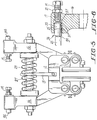
- FIGURE 5 there is shown an alternative embodiment of the invention wherein two actuating springs 27 and 29 are used, one for independently biasing each of the levers 16.
- Each of the springs 27 and 29 seats on a central plate 13 which is fastened to the bracket 12.
- the brake assembly of this invention provides several advantages over prior art caliper disk brakes. Biasing the brake shoes on the brake arms ensures that the brake shoes will not drag on the disk when the brakes are applied or lifted, thereby quieting the brake.
- the use of levers in the latch assembly provides the mechanical advantage sufficient to allow the use of a small latch solenoid having a longer stroke. The longer stroke solenoid allows the use of the stepped core whereby noise may be reduced.
- the use of two actuating springs on the brake assembly assures that spring failure will not completely prevent the brake from operating.
- the modular construction of the assembly enables one unit to be used in lighter duty elevators, and multiple units to be used in heavier duty elevators. It also allows repair and cleaning of the latch assembly components while the brake is set.
Landscapes
- Engineering & Computer Science (AREA)
- General Engineering & Computer Science (AREA)
- Mechanical Engineering (AREA)
- Physics & Mathematics (AREA)
- Electromagnetism (AREA)
- Braking Arrangements (AREA)
- Cage And Drive Apparatuses For Elevators (AREA)
Abstract
Description
- This invention relates to an improved brake assembly for use in holding an elevator car at a landing, which is also operable to stop the car under emergency conditions, as in a power failure or overspeed. More particularly, this invention relates to a caliper brake assembly for engagement with a disk secured to the elevator machine shaft or drive sheave to hold the latter against rotation.
- Disk brakes which act upon a disk secured to an elevator machine shaft to hold the elevator car in place at landings are known in the prior art. Disk brakes in the prior art which have been adapted for elevator use have been full plate disk brakes wherein the brake shoes are operable to engage the periphery of the disk to hold the car in place. Full plate disk brakes may be prone to dirt and moisture problems, and are not amenable to solenoid stroke variations due to their mode of operation. They are also noisy due to the difficulty in controlling motion in the relatively short stroke of the flat faced armature.
- A disk brake is also known from DE-A-2646736 for use with handling equipment, such as travelling cranes, in which the disk is braked by a pair of opposed pads mounted on sprung levers and actuated by an electromagnet.
- This invention relates to a disk brake assembly for use in an elevator system wherein the disk brakes are caliper-type brakes which are operative to engage a brake disk mounted on the machine shaft or drive sheave to hold the car in place at landings. More particularly, the disk brake assembly of this invention comprises:
- a) a pair of brake shoes mounted on an associated pair of brake arms, the brake shoes having opposed braking surfaces; and
- b) a brake disk interposed between the brake shoes, the brake disk having opposite side surfaces facing respective ones of the braking surfaces; characterised in that the assembly further comprises
- c) spring means which act on the brake arms to bias the brake shoes toward each other; and
- d) latching means including:
- i) a pair of pivotally mounted levers for engagement with the brake arms to hold the latter against the bias of the spring means; and
- ii) solenoid latch actuating means including a solenoid plunger operably engaging the levers to selectively hold the latter against the brake arms, the plunger being reciprocally movable between latch-on and latch-off positions to selectively latch and release the brake arms.
- The association of a latching solenoid and plunger with levers that engage with the brake arms obtains a mechanical advantage whereby smaller solenoids can be used to hold the brake in an "off" condition. Also, the plunger may have a larger stroke which provides the advantage of being able to control the noise of the plunger or core by stepping the solenoid plunger to bias the magnetic flux thus controlling the velocity and force of the plunger. The brake assembly of this invention may be spring-biased "on", so that when power to the solenoid is interrupted, the brake will engage the brake disk by reason of spring action. The spring action may be supplied to the brake shoes by a single spring, or each brake shoe can be biased independently by for example its own individual spring. In the latter case, if one spring fails the other will cause engagement of one brake shoe with the disk which will be enough to hold the elevator at a landing safely. The brake assembly may be modular whereby a number of the assemblies can be ganged on a single disk for heavier duty elevators. The construction of the brake may be such that some of its components and its solenoid can be repaired or cleaned after being detached from the assembly while the brake shoes engage the brake disk.
- It is therefore an object of this invention to provide an improved disk brake assembly for use in an elevator system for holding the car in place at landings and for emergency stopping of the car.
- These and other objects and advantages of the invention will become more readily apparent from the following detailed description of an exemplary preferred embodiment thereof when taken in conjunction with the accompanying drawings, in which:
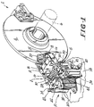
- FIGURE 1 is a perspective view of two of the brake modules and an associated disk which is keyed to the elevator machine shaft;
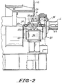
- FIGURE 2 is an elevational view partially in section showing the disk mounted on the sheave;
- FIGURE 3 is a top plan view of one of the brake modules;
- FIGURE 4 is a front elevational view of the solenoid operated brake latch portion of the assembly;
- FIGURE 5 is a view similar to FIGURE 3 but showing the use of separate actuating springs for each brake arm; and
- FIGURE 6 is a fragmented sectional view of the lever-engaging pin on the brake arms.
- Referring now to FIGURE 1, two identical brake modules 2 are shown operably interacting with a
brake disk 4 which is keyed to and rotates with the shaft 6 (shown in phantom) of the elevator machine. Each module 2 includes a brake assembly 8 and abrake latch assembly 10. - FIGURES 1, 2 and 3 show details of the brake assembly 8. The brake assembly 8 includes a
bracket 12 which is fixed to the machine frame or stand 14 (shown in phantom lines in FIGURES 1 and 2) and to which twoopposed brake arms 16 are mounted for pivotal movement aboutpins 18. Abrake shoe 20 is pivotally mounted onpins 22 to thebrake arms 16 so as to flank thedisk 4. Acoil spring 24 sandwiched between eachbrake shoe 20 about itsrespective brake arm 16 biases eachbrake shoe 20 about itsrespective pin 22 and toward the inner end of anadjustable screw 23 threaded into eacharm 16, such that thebrake pads 26 on theshoes 20 remain parallel to each other and to thedisk 4. In this manner thepads 26 are prevented from dragging on thedisk 4 when the brake is lifted. A brake actuatingspring 28 is mounted inspring caps 30 carried onspring guides 32 which are secured to thebrake arms 16. Thespring 28 biases thearms 16 outwardly about thepins 18 thereby biasing thebrake shoes 20 against thedisk 4. This action will occur whenever power is removed from thesolenoid 36. In the event of a power failure or an emergency, the brake will automatically sit on the disk. Thespring 28 thus supplies the force needed to set the brake.Cam pins 34 are mounted on the ends of thearms 16 distal of thebrake shoes 20. - FIGURES 1 and 4 show details of the
brake latching assembly 10. Thelatch 10 includes asolenoid 36 fixed to the machine stand 14 and a solenoid actuatedplunger 38 which moves up and down in thesolenoid 36.Brackets 40 are mounted on opposite sides of thesolenoid 36 and latch levers 42 withupturned fingers 43 are pivotally mounted on thebrackets 40 viapins 44. Aclevis 46 is disposed on theplunger 38 and receives overlappingends 48 of thelevers 42. Apin 50 spans theclevis 46 and overlies theends 48 of thelevers 42 thereby interconnecting thesolenoid plunger 38 and thelevers 42. Theupturned fingers 43 on thelevers 42 engage thecam pins 34 on the brake assembly 8. - It will be appreciated that when the
latch levers 42 are disconnected from themount brackets 40, and released from theclevis 46 by removingpin 50, thecore pin 38 can simply be pulled up out of the solenoid core for cleaning or replacement. - When the
solenoid 36 is supplied with electricity, theplunger 38 will be recessed in thesolenoid 36, and theclevis 46, levers 42 andcam pins 34 will be in the positions shown in solid lines in FIGURE 4. Thecam pins 34 will thus be latched causing compression of the brake actuatingspring 28 and lifting thebrake shoes 20 off thebrake disk 4. When the elevator car is properly levelled at a landing, the elevator controller switches off electrical power to thesolenoid 36 allowing theplunger 38 andclevis 46 to rise to the position shown in phantom lines in FIGURE 4. This movement causes thelevers 42 to pivot about thepins 44 to the respective positions shown in phantom in FIGURE 4 whereby the actuatingspring 28 is able to pivot thebrake arms 16 about thepins 18 causing thebrake shoe pads 26 to engage thedisk 4. The enabling of the actuatingspring 28 is the result of movement of thelever fingers 43 away from thecam pins 34, as shown in phantom lines in FIGURE 4. The brake will thus be set on thedisk 4, and the car held at the landing. When it is desired to move the car away from the landing, the controller switches power back on to thesolenoid 36. This causes theplunger 38 to be drawn back into thesolenoid 36 to return theclevis 46, levers 42 andcam pins 34 back to the respective positions shown in solid lines in FIGURE 4. Movement of thecam pins 34 causes thebrake pads 26 to lift off of thedisk 4, and compresses the actuatingspring 28. - Referring to FIGURE 6, details of the lever
contact pin assembly 34 are shown. At the outer end of thebrake arm 16, a threadedbore 17 is formed to receive anadjustment bolt 19 carrying alock nut 21. Thebore 17 opens into asmooth bore 23 in which apin 25 is slideably disposed. Thepin 25 has roundedend walls pin 25 in place within thebore 23. - The
adjustment bolt 19 allows thepin 25 to move toward and away fromfinger 43 to thereby allow the positioning of thelevers 42 to be modified. - In FIGURE 5 there is shown an alternative embodiment of the invention wherein two actuating
springs levers 16. Each of thesprings central plate 13 which is fastened to thebracket 12. By using two separate springs, if one fails, the other one will still be operable to move one of the brake shoes against thedisk 4 to provide some braking of the car at the landing. A single spring separated into two independent portions could also be used. - It will be appreciated that the brake assembly of this invention provides several advantages over prior art caliper disk brakes. Biasing the brake shoes on the brake arms ensures that the brake shoes will not drag on the disk when the brakes are applied or lifted, thereby quieting the brake. The use of levers in the latch assembly provides the mechanical advantage sufficient to allow the use of a small latch solenoid having a longer stroke. The longer stroke solenoid allows the use of the stepped core whereby noise may be reduced. The use of two actuating springs on the brake assembly assures that spring failure will not completely prevent the brake from operating. The modular construction of the assembly enables one unit to be used in lighter duty elevators, and multiple units to be used in heavier duty elevators. It also allows repair and cleaning of the latch assembly components while the brake is set.
- Since many changes and variations of the disclosed embodiments of the invention may be made without departing from the inventive concept, it is not intended to limit the invention otherwise than as required by the appended claims.
Claims (8)
- A caliper brake assembly (8) comprising:a) a pair of brake shoes (20) mounted on an associated pair of brake arms (16), said brake shoes (20) having opposed braking surfaces (26); andb) a brake disk (4) interposed between said brake shoes (20), said brake disk (4) having opposite side surfaces facing respective ones of said braking surfaces (26); characterised in that said assembly (8) further comprises:c) spring means (28;27,29) which act on said brake arms (16) to bias said brake shoes (20) toward each other; andd) latching means (10) including:i) a pair of pivotally mounted levers (42) for engagement with said brake arms (16) to hold the latter against the bias of said spring means (28;27,29); andii) solenoid latch actuating means (36,38) including a solenoid plunger (38) operably engaging said levers (42) to selectively hold the latter against said brake arms (16), said plunger (38) being reciprocally movable between latch-on and latch-off positions to selectively latch and release said brake arms (16).
- The brake assembly (8) of claim 1, wherein said spring means (28;27,29) independently biases each said brake shoe (20) toward the other.
- The brake assembly (8) of claim 1 or 2, wherein said solenoid plunger (38) operates in a direction perpendicular to the direction of bias of said spring means (28;27,29).
- The brake assembly (8) of claim 1, 2, or 3, wherein said solenoid plunger (38) is connected to adjacent ends (48) of said levers (42) with a common connecting pin (50).
- The brake assembly (8) of claim 4, wherein said adjacent ends (48) of said levers (42) are overlapped.
- The brake assembly (8) of any of claims 1 to 5, wherein said solenoid plunger (38) can be removed from an associated solenoid coil (36) for cleaning upon disengagement from said levers (42).
- The brake assembly (8) of any of claims 1 to 6, further comprising contact means for providing operating contact between said brake arms (16) and said levers (42), said contact means comprising contact pins (34) slideably mounted on ends of said brake arms (16) distal of said brake shoes (20), and arranged for engagement with said levers (42), and means (19,21) for adjustably moving said contact pins (34) toward and away from said levers (42) to modify the positioning of said levers (42).
- The brake assembly (8) of claim 7, wherein said contact pins (34) are provided with rounded ends engaging said levers (42) for providing point contact between said brake arms (16) and levers (42).
Applications Claiming Priority (3)
| Application Number | Priority Date | Filing Date | Title |
|---|---|---|---|
| US50862790A | 1990-04-13 | 1990-04-13 | |
| US508627 | 1990-04-13 | ||
| EP19910303295 EP0457436B1 (en) | 1990-04-13 | 1991-04-15 | Disc brake for elevator |
Related Parent Applications (1)
| Application Number | Title | Priority Date | Filing Date |
|---|---|---|---|
| EP91303295.9 Division | 1991-04-15 |
Publications (3)
| Publication Number | Publication Date |
|---|---|
| EP0641950A2 true EP0641950A2 (en) | 1995-03-08 |
| EP0641950A3 EP0641950A3 (en) | 1995-05-10 |
| EP0641950B1 EP0641950B1 (en) | 1997-03-05 |
Family
ID=24023449
Family Applications (2)
| Application Number | Title | Priority Date | Filing Date |
|---|---|---|---|
| EP94203356A Expired - Lifetime EP0641950B1 (en) | 1990-04-13 | 1991-04-15 | Disc brake for elevator |
| EP19910303295 Expired - Lifetime EP0457436B1 (en) | 1990-04-13 | 1991-04-15 | Disc brake for elevator |
Family Applications After (1)
| Application Number | Title | Priority Date | Filing Date |
|---|---|---|---|
| EP19910303295 Expired - Lifetime EP0457436B1 (en) | 1990-04-13 | 1991-04-15 | Disc brake for elevator |
Country Status (6)
| Country | Link |
|---|---|
| EP (2) | EP0641950B1 (en) |
| JP (1) | JPH04226291A (en) |
| AU (1) | AU624039B2 (en) |
| CA (1) | CA2036363C (en) |
| DE (2) | DE69111687T2 (en) |
| ES (2) | ES2078439T3 (en) |
Cited By (6)
| Publication number | Priority date | Publication date | Assignee | Title |
|---|---|---|---|---|
| EP0876990A2 (en) * | 1997-04-30 | 1998-11-11 | MANNESMANN Aktiengesellschaft | Emergency stopping brake |
| AU737625B2 (en) * | 1998-06-08 | 2001-08-23 | Kone Corporation | Holding brake for a traction sheave elevator |
| DE10315985A1 (en) * | 2003-04-07 | 2004-10-28 | Bischoff Autofedern Und Nutzfahrzeugteile Gmbh | Stop brake for fixing a rotatable brake disk, comprises solenoid which has control electronics, which when brake is ventilated and armature is activated, it sets off the current flow through solenoid |
| CN105314562A (en) * | 2014-08-04 | 2016-02-10 | 株式会社日立制作所 | Windlass for elevator |
| CN110831883A (en) * | 2017-05-24 | 2020-02-21 | 三菱电机株式会社 | Traction machine for elevator |
| WO2024112278A1 (en) * | 2022-11-22 | 2024-05-30 | Ekdöksan Döküm Metal Otomoti̇v San. Ve Ti̇c. Ltd. Şti̇. | Armature disc centering system for electromagnetic elevator brake |
Families Citing this family (13)
| Publication number | Priority date | Publication date | Assignee | Title |
|---|---|---|---|---|
| DE19849749A1 (en) * | 1998-10-28 | 2000-05-04 | Mayr Christian Gmbh & Co Kg | Part-pad spring pressure brake to engage a rotating disc |
| WO2007127453A1 (en) | 2006-04-28 | 2007-11-08 | Electronic Theater Controls, Inc. | Lift assembly, system, and method |
| JP4932799B2 (en) * | 2007-09-13 | 2012-05-16 | 曙ブレーキ工業株式会社 | Pad holder with adjuster function |
| WO2009062164A2 (en) | 2007-11-08 | 2009-05-14 | Electronic Theatre Controls, Inc. | Lift assembly systems and methods |
| JP2009208914A (en) * | 2008-03-05 | 2009-09-17 | Toshiba Elevator Co Ltd | Vertical vibration suppressing device for elevator |
| EP2501636B1 (en) | 2009-11-18 | 2015-04-08 | Electronic Theatre Controls, Inc. | Lift assembly systems and methods |
| JP5361774B2 (en) * | 2010-03-24 | 2013-12-04 | カヤバ工業株式会社 | Caliper brake device |
| JP6018906B2 (en) * | 2012-12-21 | 2016-11-02 | 株式会社日立製作所 | Brake for hoisting machine in elevator |
| US10183850B2 (en) | 2012-12-21 | 2019-01-22 | Electronic Theatre Controls, Inc. | Compact hoist system |
| CN104370237B (en) * | 2014-11-10 | 2017-01-11 | 巨人通力电梯有限公司 | Traction machine brake |
| GB2566497B (en) * | 2017-09-15 | 2020-07-29 | Illinois Tool Works | Braking system for electromagnetic motors |
| CN112268081B (en) * | 2020-10-26 | 2022-02-08 | 河北翔金超环保科技有限公司 | Eccentric wear prevention electric hydraulic brake |
| CN114132815A (en) * | 2021-12-31 | 2022-03-04 | 中山天达电梯科技有限公司 | Home elevator car arresting gear |
Citations (3)
| Publication number | Priority date | Publication date | Assignee | Title |
|---|---|---|---|---|
| GB1094752A (en) * | 1964-02-22 | 1967-12-13 | J H Carruthers & Company Ltd | Improvements relating to disc brakes |
| DE2646736A1 (en) * | 1975-10-16 | 1977-04-28 | Fradisc Gagny Fa | CALIPER FOR DISC BRAKES |
| GB1581829A (en) * | 1977-05-16 | 1980-12-31 | Wild & Co Ltd M B | Brake apparatus for a winding drum |
Family Cites Families (2)
| Publication number | Priority date | Publication date | Assignee | Title |
|---|---|---|---|---|
| GB869070A (en) * | 1956-10-27 | 1961-05-25 | Dunlop Rubber Co | Improvements in braking systems |
| US4696377A (en) * | 1985-09-27 | 1987-09-29 | Ltv Energy Products Company | Brake system for drawworks |
-
1991
- 1991-02-14 CA CA 2036363 patent/CA2036363C/en not_active Expired - Fee Related
- 1991-03-15 AU AU73598/91A patent/AU624039B2/en not_active Ceased
- 1991-04-15 EP EP94203356A patent/EP0641950B1/en not_active Expired - Lifetime
- 1991-04-15 DE DE1991611687 patent/DE69111687T2/en not_active Expired - Fee Related
- 1991-04-15 ES ES91303295T patent/ES2078439T3/en not_active Expired - Lifetime
- 1991-04-15 JP JP3109847A patent/JPH04226291A/en active Pending
- 1991-04-15 DE DE1991625039 patent/DE69125039T2/en not_active Expired - Fee Related
- 1991-04-15 ES ES94203356T patent/ES2101433T3/en not_active Expired - Lifetime
- 1991-04-15 EP EP19910303295 patent/EP0457436B1/en not_active Expired - Lifetime
Patent Citations (3)
| Publication number | Priority date | Publication date | Assignee | Title |
|---|---|---|---|---|
| GB1094752A (en) * | 1964-02-22 | 1967-12-13 | J H Carruthers & Company Ltd | Improvements relating to disc brakes |
| DE2646736A1 (en) * | 1975-10-16 | 1977-04-28 | Fradisc Gagny Fa | CALIPER FOR DISC BRAKES |
| GB1581829A (en) * | 1977-05-16 | 1980-12-31 | Wild & Co Ltd M B | Brake apparatus for a winding drum |
Cited By (9)
| Publication number | Priority date | Publication date | Assignee | Title |
|---|---|---|---|---|
| EP0876990A2 (en) * | 1997-04-30 | 1998-11-11 | MANNESMANN Aktiengesellschaft | Emergency stopping brake |
| EP0876990A3 (en) * | 1997-04-30 | 1999-10-13 | MANNESMANN Aktiengesellschaft | Emergency stopping brake |
| AU737625B2 (en) * | 1998-06-08 | 2001-08-23 | Kone Corporation | Holding brake for a traction sheave elevator |
| DE10315985A1 (en) * | 2003-04-07 | 2004-10-28 | Bischoff Autofedern Und Nutzfahrzeugteile Gmbh | Stop brake for fixing a rotatable brake disk, comprises solenoid which has control electronics, which when brake is ventilated and armature is activated, it sets off the current flow through solenoid |
| CN105314562A (en) * | 2014-08-04 | 2016-02-10 | 株式会社日立制作所 | Windlass for elevator |
| CN105314562B (en) * | 2014-08-04 | 2017-10-24 | 株式会社日立制作所 | Winch for elevator |
| CN110831883A (en) * | 2017-05-24 | 2020-02-21 | 三菱电机株式会社 | Traction machine for elevator |
| CN110831883B (en) * | 2017-05-24 | 2021-02-02 | 三菱电机株式会社 | Traction machine for elevator |
| WO2024112278A1 (en) * | 2022-11-22 | 2024-05-30 | Ekdöksan Döküm Metal Otomoti̇v San. Ve Ti̇c. Ltd. Şti̇. | Armature disc centering system for electromagnetic elevator brake |
Also Published As
| Publication number | Publication date |
|---|---|
| DE69111687D1 (en) | 1995-09-07 |
| JPH04226291A (en) | 1992-08-14 |
| DE69125039T2 (en) | 1997-10-02 |
| DE69125039D1 (en) | 1997-04-10 |
| AU624039B2 (en) | 1992-05-28 |
| DE69111687T2 (en) | 1996-05-02 |
| EP0457436A1 (en) | 1991-11-21 |
| EP0641950B1 (en) | 1997-03-05 |
| AU7359891A (en) | 1991-10-17 |
| ES2101433T3 (en) | 1997-07-01 |
| ES2078439T3 (en) | 1995-12-16 |
| EP0457436B1 (en) | 1995-08-02 |
| CA2036363A1 (en) | 1991-10-14 |
| EP0641950A3 (en) | 1995-05-10 |
| CA2036363C (en) | 1999-08-24 |
Similar Documents
| Publication | Publication Date | Title |
|---|---|---|
| US5101939A (en) | Disk brake for elevator | |
| EP0641950B1 (en) | Disc brake for elevator | |
| JP4709650B2 (en) | Remote resettable ropeless emergency stop for elevators | |
| JP5212971B2 (en) | Brake device, elevator device, method for detecting the function of a brake device, and an updated set | |
| US10562739B2 (en) | Synchronized electronic safety actuator | |
| CN103459290A (en) | Elevator braking system | |
| US6520299B2 (en) | Disk brake for elevator drive | |
| JP2002532366A (en) | Low press governor mechanism for elevator car | |
| USRE38835E1 (en) | Remote brake release mechanism for an elevator machine | |
| CN106715307B (en) | Elevator brake | |
| EP0388299B1 (en) | Safety brake for escalator | |
| CN1019566B (en) | Safety disc brake for lifts | |
| CN110790109B (en) | Electric safety actuator assembly for elevator system | |
| CA1104954A (en) | Drum brake | |
| JP2010514645A (en) | Elevating system having an elevator box with a brake device for holding and braking the elevator box in the area of the elevator box and a method for holding and braking an elevator box of this type | |
| US6425462B1 (en) | Gravity-assisted elevator brake/clutch | |
| US5899304A (en) | Motor brake | |
| US6478124B2 (en) | Brake device for a drive machine of an elevator | |
| EP1481937A1 (en) | Modular and adaptable brake system for an elevator sheave | |
| WO2021090474A1 (en) | Elevator device | |
| US11858781B2 (en) | Frictionless electronic safety actuator | |
| JPWO2002053485A1 (en) | Elevator emergency braking system | |
| CN216272558U (en) | Electromagnetic device for elevator brake, elevator brake and elevator system | |
| US20240228228A1 (en) | Stationary mechanical brake for linear motor elevators | |
| JPH0977396A (en) | Braking device for elevator |
Legal Events
| Date | Code | Title | Description |
|---|---|---|---|
| PUAI | Public reference made under article 153(3) epc to a published international application that has entered the european phase |
Free format text: ORIGINAL CODE: 0009012 |
|
| AC | Divisional application: reference to earlier application |
Ref document number: 457436 Country of ref document: EP |
|
| AK | Designated contracting states |
Kind code of ref document: A2 Designated state(s): DE ES FR GB IT |
|
| PUAL | Search report despatched |
Free format text: ORIGINAL CODE: 0009013 |
|
| AK | Designated contracting states |
Kind code of ref document: A3 Designated state(s): DE ES FR GB IT |
|
| 17P | Request for examination filed |
Effective date: 19950710 |
|
| GRAG | Despatch of communication of intention to grant |
Free format text: ORIGINAL CODE: EPIDOS AGRA |
|
| 17Q | First examination report despatched |
Effective date: 19960125 |
|
| GRAH | Despatch of communication of intention to grant a patent |
Free format text: ORIGINAL CODE: EPIDOS IGRA |
|
| GRAH | Despatch of communication of intention to grant a patent |
Free format text: ORIGINAL CODE: EPIDOS IGRA |
|
| ITF | It: translation for a ep patent filed | ||
| GRAA | (expected) grant |
Free format text: ORIGINAL CODE: 0009210 |
|
| AC | Divisional application: reference to earlier application |
Ref document number: 457436 Country of ref document: EP |
|
| AK | Designated contracting states |
Kind code of ref document: B1 Designated state(s): DE ES FR GB IT |
|
| REF | Corresponds to: |
Ref document number: 69125039 Country of ref document: DE Date of ref document: 19970410 |
|
| ET | Fr: translation filed | ||
| REG | Reference to a national code |
Ref country code: ES Ref legal event code: FG2A Ref document number: 2101433 Country of ref document: ES Kind code of ref document: T3 |
|
| PLBE | No opposition filed within time limit |
Free format text: ORIGINAL CODE: 0009261 |
|
| STAA | Information on the status of an ep patent application or granted ep patent |
Free format text: STATUS: NO OPPOSITION FILED WITHIN TIME LIMIT |
|
| 26N | No opposition filed | ||
| PGFP | Annual fee paid to national office [announced via postgrant information from national office to epo] |
Ref country code: ES Payment date: 19980415 Year of fee payment: 8 |
|
| PGFP | Annual fee paid to national office [announced via postgrant information from national office to epo] |
Ref country code: DE Payment date: 19990326 Year of fee payment: 9 |
|
| PG25 | Lapsed in a contracting state [announced via postgrant information from national office to epo] |
Ref country code: ES Free format text: LAPSE BECAUSE OF NON-PAYMENT OF DUE FEES Effective date: 19990416 |
|
| PGFP | Annual fee paid to national office [announced via postgrant information from national office to epo] |
Ref country code: FR Payment date: 20000313 Year of fee payment: 10 |
|
| PGFP | Annual fee paid to national office [announced via postgrant information from national office to epo] |
Ref country code: GB Payment date: 20000321 Year of fee payment: 10 |
|
| PG25 | Lapsed in a contracting state [announced via postgrant information from national office to epo] |
Ref country code: DE Free format text: LAPSE BECAUSE OF NON-PAYMENT OF DUE FEES Effective date: 20010201 |
|
| PG25 | Lapsed in a contracting state [announced via postgrant information from national office to epo] |
Ref country code: GB Free format text: LAPSE BECAUSE OF NON-PAYMENT OF DUE FEES Effective date: 20010415 |
|
| PG25 | Lapsed in a contracting state [announced via postgrant information from national office to epo] |
Ref country code: FR Free format text: THE PATENT HAS BEEN ANNULLED BY A DECISION OF A NATIONAL AUTHORITY Effective date: 20010430 |
|
| REG | Reference to a national code |
Ref country code: ES Ref legal event code: FD2A Effective date: 20010503 |
|
| GBPC | Gb: european patent ceased through non-payment of renewal fee |
Effective date: 20010415 |
|
| REG | Reference to a national code |
Ref country code: FR Ref legal event code: ST |
|
| PG25 | Lapsed in a contracting state [announced via postgrant information from national office to epo] |
Ref country code: IT Free format text: LAPSE BECAUSE OF NON-PAYMENT OF DUE FEES Effective date: 20050415 |