EP0641269B1 - Improved electrode for high current density plasma arc torch - Google Patents
Improved electrode for high current density plasma arc torch Download PDFInfo
- Publication number
- EP0641269B1 EP0641269B1 EP93910938A EP93910938A EP0641269B1 EP 0641269 B1 EP0641269 B1 EP 0641269B1 EP 93910938 A EP93910938 A EP 93910938A EP 93910938 A EP93910938 A EP 93910938A EP 0641269 B1 EP0641269 B1 EP 0641269B1
- Authority
- EP
- European Patent Office
- Prior art keywords
- insert
- electrode
- emissive
- area
- torch
- Prior art date
- Legal status (The legal status is an assumption and is not a legal conclusion. Google has not performed a legal analysis and makes no representation as to the accuracy of the status listed.)
- Revoked
Links
Images


Classifications
-
- H—ELECTRICITY
- H05—ELECTRIC TECHNIQUES NOT OTHERWISE PROVIDED FOR
- H05H—PLASMA TECHNIQUE; PRODUCTION OF ACCELERATED ELECTRICALLY-CHARGED PARTICLES OR OF NEUTRONS; PRODUCTION OR ACCELERATION OF NEUTRAL MOLECULAR OR ATOMIC BEAMS
- H05H1/00—Generating plasma; Handling plasma
- H05H1/24—Generating plasma
- H05H1/26—Plasma torches
- H05H1/32—Plasma torches using an arc
- H05H1/34—Details, e.g. electrodes, nozzles
- H05H1/3452—Supplementary electrodes between cathode and anode, e.g. cascade
-
- H—ELECTRICITY
- H05—ELECTRIC TECHNIQUES NOT OTHERWISE PROVIDED FOR
- H05H—PLASMA TECHNIQUE; PRODUCTION OF ACCELERATED ELECTRICALLY-CHARGED PARTICLES OR OF NEUTRONS; PRODUCTION OR ACCELERATION OF NEUTRAL MOLECULAR OR ATOMIC BEAMS
- H05H1/00—Generating plasma; Handling plasma
- H05H1/24—Generating plasma
- H05H1/26—Plasma torches
- H05H1/32—Plasma torches using an arc
- H05H1/34—Details, e.g. electrodes, nozzles
- H05H1/3442—Cathodes with inserted tip
Definitions
- This invention relates in general to plasma arc cutting torches. More specifically it relates to an improved electrode and insert cooling method for use in low current, high definition torches.
- a high emissivity material such as hafnium or zirconium press fit into the bottom face of a copper electrode.
- a current is applied to the electrode.
- a pilot arc is typically formed within the torch between the electrode and an adjacent nozzle. The arc then transfers to a workpiece in conjunction with a ramping up of the arc current to a full operating value.
- the insert is cylindrical and has a diameter of about 0.070 inch (17.8 mm) for torches carrying currents varying from 20 to 260 amperes. This value was chosen by Hypertherm, Inc., the assignee of the present application, in the 1980's during the development of a 260 ampere oxygen plasma cutting system. It has remained the standard insert size ever since.
- French Patent Application FR-A-2173875 is concerned with the relationship between the nozzle opening and the cathodic element diameter of a cooled electrode.
- This document on which is based the preamble of claims 1 and 11, discloses a cathodic diameter of 8/10 of the nozzle opening as giving a more reliable torch whose essential components have a longer lifetime.
- Another principal advantage is to provide an electrode and method of cooling the electrode that exhibits significantly improved wear and cut quality.
- a further object is to provide an electrode with the foregoing advantages which is also less costly than conventional electrodes for comparable applications.
- the invention provides an electrode as defined by the precharacterising portion of claim 1 wherein the size of the emissive spot is selected in coordination with the operating current level so that the current density of the arc rooted at the insert area during cutting is substantially constant at a value of at least 1.860x10 8 A/m 2 (1.2 x 10 5 amperes/inch 2 ), the emissive surface area is sufficiently small that the insert material in said emissive area does not boil, and the diameter of the insert exceeds the diameter of said emissive spot by an amount that isolates the arc from the electrode.
- the insert is preferably hafnium and the body is preferably copper.
- the insert is preferably cylindrical.
- a flow of a cooling fluid such as water is circulated within the electrode and in particular across a bottom end wall of the electrode containing the insert.
- the insert extends completely through the bottom wall to place it in direct contact with the water.
- the interior bore of the electrode preferably includes an annular recess in the bottom wall that surrounds an upper portion of the insert and an intermediate ring of copper body material.
- a water inlet tube extends into this recess in a spaced relationship.
- This "hollowmilled” constructing (i) provides a large area heat transmitting surface in direct contact with the water adjacent the insert, (ii) provides high flow velocities for the water at the bottom wall of the torch, and (iii) avoids the presence of vapour blocks, whether within the electrode or at the electrode-coolant interface.
- the invention involves extending the life of an electrode as defined in the precharacterising portion of claim 11, wherein the area of the insert is not sufficiently large to result in a boiling of the insert (44) material during cutting and the diameter of the insert (44) exceeds the diameter of said emission spot (46) by an amount that isolates the arc from the electrode (42).
- the invention thus involves sizing the insert to maximize conduction cooling via a surrounding high conductivity material.
- This sizing is preferably used in combination with known convection cooling with a fluid, preferably water, at the interior of the electrode.
- the cooling fluid is preferably in direct contact with the insert and in a high velocity flow pattern around the insert and a surrounding sleeve of copper.
- Fig. 1 shows the front parts 10 of a high definition plasma arc torch developed by Hypertherm, Inc. and identified as its HD-1070 torch. It is designed to pierce and cut metal, particularly mild steel, in a transferred arc mode, but it can be used to pierce, cut, and shape other materials. In cutting mild steel, it operates with oxygen or air as the plasma gas 12 to form a transferred arc 14.
- An electrode 16, typically formed of copper, has an insert 18 press fit into its lower end 16a.
- the arc 14 is highly constricted; the arc has a current density of 9.300x10 7 A/m 2 (60,000 amperes/inch 2 ), several times a typical current density of 3.875x10 7 A/m 2 (25,000 amperes/inch 2 ) for conventional plasma arc torches.
- the front parts include a nozzle 20 having an inner piece 22 and an outer piece 24 with a flow path 26 formed therebetween to divert away a portion 28 of the plasma gas flow 30.
- a swirl ring 32 has canted ports 32a that impart a swirl to the plasma gas flow. This swirl creates a vortex that constricts and stabilizes the arc.
- the diversion of a portion 28 of the plasma gas flow ensures a strong vortex flow through a plasma arc chamber 34 despite the relatively small cross sectional area of the nozzle exit orifice 36 at the outer nozzle piece 24. This strong vortex flow stabilizes the position of the arc 14 on the insert 18.
- low currents e.g.
- the emission spot on the insert 18 is generally circular and has a diameter of about 0.305 mm 0.012 inch.
- a nozzle shield 38 of the general type described in U.S. Patent No. 4,861,962 guides a flow 40 of a secondary gas onto the arc. The shield and the gas flow 40 protect the nozzle against molten metal splattered onto the torch from the workpiece which can produce gouging or double arcing.
- the electrode 16 is hollowed as shown with a water inlet tube extending down into the electrode as shown.
- the insert 18 is generally cylindrical and has a diameter of 1.778 mm (0.070 inch). As noted above, with this construction, when the torch is operated to cut at low currents (15-70 amperes) the electrode exhibits rapid wear. At 15 amperes, the insert shows a pit of 0.762 mm (0.030 inch) depth after about only 50 starts. This poor wear performance appears despite the use of the wear reduction invention described in U.S. Patent No. 5,070,227. This '227 invention uses as a model that the insert material is molten during operation and that a strong vortex gas flow blows away the molten material upon arc termination. This model does not, however, explain the wear of the electrode at low currents.
- Fig. 2 shows an electrode 42 according to the present invention suitable for use in the high definition torch shown in Fig. 1.
- the electrode 42 has a cylindrical body 42a that extends along the centerline of the torch when it is installed for use. Threads 42b replaceably secure the electrode to a cathode block, not shown, which in turn is connected to the negative terminal of a conventional D.C. power supply, also not shown.
- a flange 42c with an outwardly facing annular recess 42d receives an o-ring to provide a fluid seal around the electrode.
- the lower end of the electrode narrows slightly before its outer surface slopes to a generally planar end surface 42e that faces the nozzle exit orifice 36.
- An insert 44 of a high emission material preferably hafnium, is centered on the end face 42e. It is generally cylindrical with a circular end surface 44a that lies directly over the exit orifice 36 and is exposed to the plasma gas in the chamber 34.
- the insert 44 is press fit into a suitable bore drilled into a bottom wall 42f of the electrode body.
- the insert 44 serves the same purpose as the insert 18 in the Fig. 1 electrode 16, but its construction differs in two significant ways.
- a first principal feature of the invention is that the diameter of the electrode is not constant for all torches and all operating currents, as was the case heretofore. Rather, the diameter coordinates with the value of the operating current (I) carried by the electrode to the transferred arc 14.
- the relationship between the current I and the area A of the insert emission surface 44a exposed to the plasma gas in the plasma chamber 36 vary so that the current density I/A is generally constant.
- the diameter of the insert is chosen by at least as large as the emission spot 46 on the insert at the selected current level, but not significantly larger.
- a narrow annular border 44b (Fig. 2A) of insert material is provided around the emission spot to ensure that the arc does not attack the body end surface 42e immediately adjacent the insert.
- the following table shows the results of a series of tests different insert sizes in the electrode 42 for different maximum operating currents in the low current range, about 15 to about 70 amperes.
- CURRENT DENSITY 1.3X10 5 1.3X10 5 1.2X10 5 1.3X10 5 DIAMETER OF INSERT mm(inch) 0.457 (0.018) 0.635 (0.025) 0.813 (0.032) 0.965 (0.038)
- the preferred insert diameter values listed include the border 44b. These values were determined empirically by operating the torch through a life test and then measuring the wear of the insert, both in depth and laterally. The two standard life tests were used. One utilized operating cycles of four seconds on, 10 seconds off. The second test used operating cycles of 1 minute on, 10 seconds off. The electrode 42 reached applicants' life goal of 800 starts for the first test and 240 starts for the second test with an acceptable wear depth of up to 1.016 mm (0.040 inch) for all of the current levels indicated in the Table. This represents an increase in the life of the electrode over standard electrode designs of about five times.
- the insert preferably extends axially all the way through the bottom wall 42f to a hollow interior 48.
- a tube 50 introduces a flow 52 of a coolant, preferably water, that circulates through the inside of the electrode, and in particular across the interior or rear surface of the bottom wall 42f.
- the flow exits the electrode via the annular passage 54 defined by the tube and the inner wall of the electrode.
- the flow rate is preferably 4 to 5 liters per minute at an incoming temperature of less than 40°C.
- the electrode is also preferably "hollowmilled", that is, it has an annular recess 56 is formed in the rear surface of the bottom wall 42c to enhance the surface area of the body material, preferably copper, in a heat exchanging relationship with the water.
- the recess also enhances the flow velocity across this rear surface.
- the rear surface 44c of the insert is also in direct contact with the coolant since it extends through the wall.
- the excellent heat conduction of copper (398 watts/m°C) transfers heat effectively in a lateral direction from the hafnium to the coolant.
- Hafnium exhibits thermal properties (22 watts/m°C) more like those of an insulator.
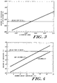
- each 0.025 mm (0.001 inch) in diameter correlates with an increase in the hafnium temperature of about 300°C.
- Fig. 3 also suggests that the insulating properties of hafnium will cause the emission spot to boil at 1.778 mm (0.070 inch) diameter, the present standard insert size.
- Fig. 3, or a like empirical graph for other torch designs or other operating conditions, provides guidance in selecting the size of the border that can be tolerated without boiling the insert material.
- Fig. 4 demonstrates the affect of a hollowmill electrode (Fig. 2) on the temperature at the rear surface of the electrode as compared to a conventional electrode (Fig. 1).
- the hollowmill design of Fig. 2 decreases the temperature at the rear surface of the bottom wall 42f by about 12° regardless of the temperature of the incoming coolant. This is significant since at a temperature of 100°C the water will boil. Boiling creates a vapor layer between the water and the copper body of the electrode which reduces the heat transfer substantially.
- the annular recess 56 assists in the cooling by providing a greater surface area for heat transfer and with a narrowed cross-sectional flow area providing an enhanced flow velocity. This heat transfer area is also physically close to the insert, surrounding at least a portion of it. It therefore provides a short, efficient thermal path from the insert to the coolant flow.
- the electrode 42 is about 1.2 inch long, has a side wall thickness of 0.762 mm (0.03 inch) and a bottom wall thickness, measured axially, of 1.956 mm (0.077 inch)
- the recess is 2.108 mm (0.083 inch) wide and the copper body portion extending from the insert to the recess has a diameter of 3.302 mm (0.130 inch).
- the insert also has a length of 0.20 inch. The diameter, of course, varies with the current according to the present invention.
Description
| OPERATING CURRENT (amps) | 15 | 30 | 50 | 70 |
| DIAMETER OF EMISSION SPOT mm(inch) | 0.305 (0.012) | 0.432 (0.017) | 0.584 (0.023) | 0.660 (0.026) |
| AREA OF EMISSION SPOT m2(inch2) | 7.29x10⁻⁸ (1.13X10⁻⁴) | 1.00x10⁻⁷ (2.27X10⁻⁴) | 2.00x10⁻⁷ (4.15X10⁻⁴) | 3.00x10⁻⁷ (5.31X10⁻⁴) ) |
| CURRENT DENSITY | 1.3X10⁵ | 1.3X10⁵ | 1.2X10⁵ | 1.3X10⁵ |
| DIAMETER OF INSERT mm(inch) | 0.457 (0.018) | 0.635 (0.025) | 0.813 (0.032) | 0.965 (0.038) |
Claims (15)
- An electrode (42) for a plasma arc cutting torch, the electrode having (i) a body (42a) formed of a material having a high thermal heat conductivity and extending along the central axis of said torch to a bottom end, and (ii) an insert (44) of a material having a high thermionic emission that is secured in the bottom end (42f) of the body (42a) to provide an emissive surface (44a) with an area A exposed to the plasma gas and with an emissive spot (46) that becomes molten during cutting, wherein the said insert (44) has an emissive surface area (44a) corresponding to the level of the operating current carried by the electrode (42), said emissive surface area (44a) being (i) at least equal to the area of the emissive spot (46) produced by cutting at a given operating current level, whereby a constant current density over said insert emissive area (44a) of 9.300x10⁷A/m2 (6.O x 104 amperes/inch2) is provided, characterised in that the size of said emissive spot (46) is selected in coordination with the operating current level so that the current density of the arc rooted at the insert area during cutting is substantially constant at a value of at least 1.860x10⁸A/m2 (1.2 x 10⁵ amperes/inch2) the emissive surface area (44a) is sufficiently small that the insert material in said emissive area does not boil, and the diameter of the insert (44) exceeds the diameter of said emissive spot (46) by an amount that isolates the arc from the electrode (42).
- The electrode (42) of claim 1 wherein the insert (44) has a generally circular cross section.
- The electrode (42) of claims 1 or 2 wherein said insert (44) is press fit into said body (42a).
- The electrode (42) of claims 1 or 2 wherein said body (42a) is hollow except for a bottom end wall (42f) that holds the insert.
- The electrode (42) of claim 4 further comprising means for circulating a cooling fluid in said hollow electrode (42) interior to promote a convection cooling of the bottom wall (42f).
- The electrode (42) of claim 5 wherein said circulating means comprises an open-ended coolant inlet tube (50) mounted within the electrode (42) in a mutually spaced relationship to define a circulating flow (52) path for said cooling fluid within said electrode (42) with a high velocity flow across said bottom wall (42f).
- The electrode (42) of claim 4 wherein the insert (44) extends through said bottom wall (42f).
- The electrode (42) of claim 7 wherein said hollow interior (48) includes an annular recess (56) that surrounds the insert (44) and an intermediate portion of said body (42a) and wherein said coolant supply tube (50) extends into said recess (56).
- The electrode (42) of claim 7 wherein said coolant inlet tube (50) and said recess (53) define a narrowed flow (52) path for said circulating coolant to increase its flow velocity.
- The electrode (42) of claims 1 to 9 wherein said body (42a) is copper and said insert (44) is hafnium.
- A method of extending the life of an electrode (42) of a plasma arc cutting torch, particularly a high definition torch having a high current density and a small diameter emissive spot (46) on an insert (44) of a high thermionic emission material secured in a bottom end (42f) of a body (42a) of a high heat conductivity material, wherein the area of the insert (44) exposed to the nozzle (24) is at least as great as the area of said emissive spot (46), and a constant current density over said insert emissive area (44a) of 9.300x10⁷A/m2 (6.0 x 10⁴ amperes/inch2) is provided characterised in that the area of the insert (44) exposed to the nozzle (24) is not sufficiently large to result in a boiling of the insert (44) material during cutting and the diameter of the insert (44) exceeds the diameter of said emission spot (46) by an amount that isolates the arc from the electrode (42).
- The method of claim 11 further comprising the step of convection cooling said end wall (42f) by circulating a cooling fluid over its interior surface.
- The method of claim 12 further comprising the step of placing said insert (44) in direct contact with said cooling fluid.
- The method of claim 13 wherein said circulating and placing lowers the temperature of the interior surface of said insert by approximately 12°C.
- The method of claim 11 wherein said exposed area (44) is generally circular with a diameter in the range of 0.305mm (0.012 inch) to 0.660mm (0.026 inch) at a current in the range of about 15 amperes to about 70 amperes where said torch is a high definition torch, said body is copper, and said insert is hafnium.
Applications Claiming Priority (3)
| Application Number | Priority Date | Filing Date | Title |
|---|---|---|---|
| US07/886,067 US5310988A (en) | 1992-05-20 | 1992-05-20 | Electrode for high current density plasma arc torch |
| US886067 | 1992-05-20 | ||
| PCT/US1993/004077 WO1993023193A1 (en) | 1992-05-20 | 1993-04-30 | Improved electrode for high current density plasma arc torch |
Publications (3)
| Publication Number | Publication Date |
|---|---|
| EP0641269A1 EP0641269A1 (en) | 1995-03-08 |
| EP0641269A4 EP0641269A4 (en) | 1995-04-05 |
| EP0641269B1 true EP0641269B1 (en) | 1998-07-08 |
Family
ID=25388307
Family Applications (1)
| Application Number | Title | Priority Date | Filing Date |
|---|---|---|---|
| EP93910938A Revoked EP0641269B1 (en) | 1992-05-20 | 1993-04-30 | Improved electrode for high current density plasma arc torch |
Country Status (7)
| Country | Link |
|---|---|
| US (1) | US5310988A (en) |
| EP (1) | EP0641269B1 (en) |
| JP (1) | JP3141031B2 (en) |
| AU (1) | AU670291B2 (en) |
| CA (1) | CA2136203C (en) |
| DE (1) | DE69319597T2 (en) |
| WO (1) | WO1993023193A1 (en) |
Families Citing this family (25)
| Publication number | Priority date | Publication date | Assignee | Title |
|---|---|---|---|---|
| US5951888A (en) * | 1998-07-09 | 1999-09-14 | The Esab Group, Inc. | Plasma electrode with arc-starting grooves |
| US6130399A (en) * | 1998-07-20 | 2000-10-10 | Hypertherm, Inc. | Electrode for a plasma arc torch having an improved insert configuration |
| JP2001150143A (en) | 1999-11-26 | 2001-06-05 | Komatsu Sanki Kk | Electrode for plasma processing and plasma arc cutting machine |
| US6752972B1 (en) | 2000-05-10 | 2004-06-22 | Essox Research And Development, Inc. | Plasma processing method and apparatus |
| US6403915B1 (en) | 2000-08-31 | 2002-06-11 | Hypertherm, Inc. | Electrode for a plasma arc torch having an enhanced cooling configuration |
| WO2002074023A2 (en) * | 2001-03-09 | 2002-09-19 | Hypertherm, Inc. | Composite electrode for a plasma arc torch |
| US20080116179A1 (en) * | 2003-04-11 | 2008-05-22 | Hypertherm, Inc. | Method and apparatus for alignment of components of a plasma arc torch |
| US6946617B2 (en) * | 2003-04-11 | 2005-09-20 | Hypertherm, Inc. | Method and apparatus for alignment of components of a plasma arc torch |
| US20050029234A1 (en) * | 2003-08-04 | 2005-02-10 | Feng Lu | Resistance spot welding electrode |
| US7022935B1 (en) | 2003-12-08 | 2006-04-04 | Illinois Tool Works Inc. | Plasma-cutting torch with integrated high frequency starter |
| US20070045241A1 (en) * | 2005-08-29 | 2007-03-01 | Schneider Joseph C | Contact start plasma torch and method of operation |
| US10098217B2 (en) | 2012-07-19 | 2018-10-09 | Hypertherm, Inc. | Composite consumables for a plasma arc torch |
| US9662747B2 (en) | 2006-09-13 | 2017-05-30 | Hypertherm, Inc. | Composite consumables for a plasma arc torch |
| US7989727B2 (en) * | 2006-09-13 | 2011-08-02 | Hypertherm, Inc. | High visibility plasma arc torch |
| US9560732B2 (en) | 2006-09-13 | 2017-01-31 | Hypertherm, Inc. | High access consumables for a plasma arc cutting system |
| US10194516B2 (en) | 2006-09-13 | 2019-01-29 | Hypertherm, Inc. | High access consumables for a plasma arc cutting system |
| FR2923977B1 (en) | 2007-11-20 | 2010-03-26 | Air Liquide | SILVER ALLOY ELECTRODE FOR PLASMA TORCH. |
| GB201106314D0 (en) * | 2011-04-14 | 2011-06-01 | Edwards Ltd | Plasma torch |
| US9000322B2 (en) * | 2011-07-21 | 2015-04-07 | Victor Equipment Company | Method for starting and stopping a plasma arc torch |
| US8772668B2 (en) | 2011-08-19 | 2014-07-08 | Illinois Tool Works Inc. | Plasma torch and torch handle having ergonomic features |
| US8901451B2 (en) | 2011-08-19 | 2014-12-02 | Illinois Tool Works Inc. | Plasma torch and moveable electrode |
| US9040868B2 (en) | 2011-08-19 | 2015-05-26 | Illinois Tool Works Inc. | Plasma torch and retaining cap with fast securing threads |
| US9833860B1 (en) | 2016-07-22 | 2017-12-05 | Lincoln Global, Inc. | System and method for plasma arc transfer for plasma cutting |
| WO2021102147A1 (en) * | 2019-11-19 | 2021-05-27 | Hypertherm, Inc. | Consumable designs for a plasma arc torch |
| KR102315992B1 (en) * | 2019-12-07 | 2021-10-21 | 디에스미래기술(주) | High density tig arc welding torch |
Family Cites Families (16)
| Publication number | Priority date | Publication date | Assignee | Title |
|---|---|---|---|---|
| DD96879A1 (en) * | 1972-02-29 | 1973-04-12 | ||
| GB1442075A (en) * | 1974-05-28 | 1976-07-07 | V N I Pk I T Chesky I Elektros | Electrodes for arc and plasma-arc working method and apparatus for coating glassware |
| US4059743A (en) * | 1974-10-28 | 1977-11-22 | Eduard Migranovich Esibian | Plasma arc cutting torch |
| NL7509461A (en) * | 1975-08-08 | 1977-02-10 | Oce Van Der Grinten Nv | CONTROL CIRCUIT FOR A POWER CONTROL CIRCUIT AND ELECTRICAL (PHOTO) GRAPHICS COPIER FITTED WITH THIS CONTROL CIRCUIT. |
| US4133987A (en) * | 1977-12-07 | 1979-01-09 | Institut Elektrosvarki Imeni E.O. Patona Adakemii Nauk | Electrode assembly for plasma arc torches |
| JPS57171366A (en) * | 1981-04-14 | 1982-10-21 | Minolta Camera Co Ltd | Heat roller fixing device |
| SE452862B (en) * | 1985-06-05 | 1987-12-21 | Aga Ab | LIGHT BAGS LEAD |
| DE3802728A1 (en) * | 1987-01-30 | 1988-08-11 | Minolta Camera Kk | IMAGE GENERATION DEVICE |
| US4799524A (en) * | 1987-07-21 | 1989-01-24 | Claude Guermonprez | Protection and/or decorative device for apertures in walls, windows and the like |
| JPH01281461A (en) * | 1988-05-07 | 1989-11-13 | Fuji Xerox Co Ltd | Recorder and its power distribution system designing method |
| US5070227A (en) * | 1990-04-24 | 1991-12-03 | Hypertherm, Inc. | Proceses and apparatus for reducing electrode wear in a plasma arc torch |
| US4861962B1 (en) * | 1988-06-07 | 1996-07-16 | Hypertherm Inc | Nozzle shield for a plasma arc torch |
| US5225874A (en) * | 1988-11-25 | 1993-07-06 | Canon Kabushiki Kaisha | Image fixing apparatus having a pulsewisely energized heater |
| US4967055A (en) * | 1989-03-31 | 1990-10-30 | Tweco Products | Plasma torch |
| US5097111A (en) * | 1990-01-17 | 1992-03-17 | Esab Welding Products, Inc. | Electrode for plasma arc torch and method of fabricating same |
| US5105061A (en) * | 1991-02-15 | 1992-04-14 | The Lincoln Electric Company | Vented electrode for a plasma torch |
-
1992
- 1992-05-20 US US07/886,067 patent/US5310988A/en not_active Expired - Lifetime
-
1993
- 1993-04-30 WO PCT/US1993/004077 patent/WO1993023193A1/en not_active Application Discontinuation
- 1993-04-30 EP EP93910938A patent/EP0641269B1/en not_active Revoked
- 1993-04-30 DE DE69319597T patent/DE69319597T2/en not_active Revoked
- 1993-04-30 AU AU42257/93A patent/AU670291B2/en not_active Expired
- 1993-04-30 CA CA002136203A patent/CA2136203C/en not_active Expired - Lifetime
- 1993-04-30 JP JP05520262A patent/JP3141031B2/en not_active Expired - Lifetime
Also Published As
| Publication number | Publication date |
|---|---|
| JP3141031B2 (en) | 2001-03-05 |
| CA2136203A1 (en) | 1993-11-25 |
| CA2136203C (en) | 1997-05-20 |
| EP0641269A4 (en) | 1995-04-05 |
| DE69319597D1 (en) | 1998-08-13 |
| JPH07506772A (en) | 1995-07-27 |
| AU4225793A (en) | 1993-12-13 |
| US5310988A (en) | 1994-05-10 |
| AU670291B2 (en) | 1996-07-11 |
| EP0641269A1 (en) | 1995-03-08 |
| WO1993023193A1 (en) | 1993-11-25 |
| DE69319597T2 (en) | 1998-11-05 |
Similar Documents
| Publication | Publication Date | Title |
|---|---|---|
| EP0641269B1 (en) | Improved electrode for high current density plasma arc torch | |
| US5756959A (en) | Coolant tube for use in a liquid-cooled electrode disposed in a plasma arc torch | |
| EP1621052B1 (en) | Method and apparatus for alignment of components of a plasma arc torch | |
| US5451739A (en) | Electrode for plasma arc torch having channels to extend service life | |
| EP0772957B1 (en) | Electrode for a plasma arc torch | |
| EP2147583B1 (en) | Plasma arc torch cutting component with optimized water cooling | |
| EP0481958B1 (en) | Nozzle shield for a plasma arc torch | |
| EP0585977A1 (en) | Plasma arc torch with improved nozzle shield and step flow | |
| US8829385B2 (en) | Plasma arc torch cutting component with optimized water cooling | |
| US8575510B2 (en) | Nozzle for a liquid-cooled plasma burner, arrangement thereof with a nozzle cap, and liquid-cooled plasma burner comprising such an arrangement | |
| EP2029309B1 (en) | Plasma arc torch cutting component with optimized water cooling | |
| KR101607358B1 (en) | Electrode for a plasma burner | |
| US4059743A (en) | Plasma arc cutting torch | |
| WO1995024289A1 (en) | Electrode for plasma arc torch | |
| EP1224846A2 (en) | Plasma torch and method for underwater cutting | |
| CA1125385A (en) | Plasma arc torch |
Legal Events
| Date | Code | Title | Description |
|---|---|---|---|
| PUAI | Public reference made under article 153(3) epc to a published international application that has entered the european phase |
Free format text: ORIGINAL CODE: 0009012 |
|
| 17P | Request for examination filed |
Effective date: 19941130 |
|
| AK | Designated contracting states |
Kind code of ref document: A1 Designated state(s): DE FR GB IT SE |
|
| A4 | Supplementary search report drawn up and despatched |
Effective date: 19950217 |
|
| AK | Designated contracting states |
Kind code of ref document: A4 Designated state(s): DE FR GB IT SE |
|
| RIN1 | Information on inventor provided before grant (corrected) |
Inventor name: SOBR,JOHN Inventor name: BACKANDER,PATRIK Inventor name: LU, ZHIPENG 4 ELA STREET Inventor name: LUO, LIFENG R.R. 4, BOX 800 Inventor name: SANDERS, NICHOLAS, A. Inventor name: COUCH, RICHARD, W. |
|
| RIN1 | Information on inventor provided before grant (corrected) |
Inventor name: SOBR,JOHN Inventor name: BACKANDER,PATRIK Inventor name: LU, ZHIPENG 4 ELA STREET Inventor name: LUO, LIFENG R.R. 4, BOX 800 Inventor name: SANDERS, NICHOLAS, A. Inventor name: COUCH, RICHARD, W. |
|
| 17Q | First examination report despatched |
Effective date: 19960102 |
|
| GRAG | Despatch of communication of intention to grant |
Free format text: ORIGINAL CODE: EPIDOS AGRA |
|
| GRAG | Despatch of communication of intention to grant |
Free format text: ORIGINAL CODE: EPIDOS AGRA |
|
| GRAH | Despatch of communication of intention to grant a patent |
Free format text: ORIGINAL CODE: EPIDOS IGRA |
|
| GRAH | Despatch of communication of intention to grant a patent |
Free format text: ORIGINAL CODE: EPIDOS IGRA |
|
| GRAA | (expected) grant |
Free format text: ORIGINAL CODE: 0009210 |
|
| AK | Designated contracting states |
Kind code of ref document: B1 Designated state(s): DE FR GB IT SE |
|
| REF | Corresponds to: |
Ref document number: 69319597 Country of ref document: DE Date of ref document: 19980813 |
|
| ET | Fr: translation filed | ||
| ITF | It: translation for a ep patent filed |
Owner name: JACOBACCI & PERANI S.P.A. |
|
| PG25 | Lapsed in a contracting state [announced via postgrant information from national office to epo] |
Ref country code: SE Free format text: LAPSE BECAUSE OF FAILURE TO SUBMIT A TRANSLATION OF THE DESCRIPTION OR TO PAY THE FEE WITHIN THE PRESCRIBED TIME-LIMIT Effective date: 19981008 |
|
| PLAV | Examination of admissibility of opposition |
Free format text: ORIGINAL CODE: EPIDOS OPEX |
|
| PLBQ | Unpublished change to opponent data |
Free format text: ORIGINAL CODE: EPIDOS OPPO |
|
| PLBI | Opposition filed |
Free format text: ORIGINAL CODE: 0009260 |
|
| 26 | Opposition filed |
Opponent name: L'AIR LIQUIDE, SOCIETE ANONYME POUR L'ETUDE ET L'E Effective date: 19990220 |
|
| PLBF | Reply of patent proprietor to notice(s) of opposition |
Free format text: ORIGINAL CODE: EPIDOS OBSO |
|
| PLBF | Reply of patent proprietor to notice(s) of opposition |
Free format text: ORIGINAL CODE: EPIDOS OBSO |
|
| PLBF | Reply of patent proprietor to notice(s) of opposition |
Free format text: ORIGINAL CODE: EPIDOS OBSO |
|
| PLBO | Opposition rejected |
Free format text: ORIGINAL CODE: EPIDOS REJO |
|
| APAC | Appeal dossier modified |
Free format text: ORIGINAL CODE: EPIDOS NOAPO |
|
| APAE | Appeal reference modified |
Free format text: ORIGINAL CODE: EPIDOS REFNO |
|
| PLBQ | Unpublished change to opponent data |
Free format text: ORIGINAL CODE: EPIDOS OPPO |
|
| PLAB | Opposition data, opponent's data or that of the opponent's representative modified |
Free format text: ORIGINAL CODE: 0009299OPPO |
|
| APAC | Appeal dossier modified |
Free format text: ORIGINAL CODE: EPIDOS NOAPO |
|
| R26 | Opposition filed (corrected) |
Opponent name: L'AIR LIQUIDE, SOCIETE ANONYME POUR L'ETUDE ET L'E Effective date: 19990220 |
|
| REG | Reference to a national code |
Ref country code: GB Ref legal event code: IF02 |
|
| PGFP | Annual fee paid to national office [announced via postgrant information from national office to epo] |
Ref country code: FR Payment date: 20030418 Year of fee payment: 11 |
|
| PGFP | Annual fee paid to national office [announced via postgrant information from national office to epo] |
Ref country code: GB Payment date: 20030423 Year of fee payment: 11 |
|
| PGFP | Annual fee paid to national office [announced via postgrant information from national office to epo] |
Ref country code: DE Payment date: 20030430 Year of fee payment: 11 |
|
| APBU | Appeal procedure closed |
Free format text: ORIGINAL CODE: EPIDOSNNOA9O |
|
| RDAF | Communication despatched that patent is revoked |
Free format text: ORIGINAL CODE: EPIDOSNREV1 |
|
| RDAG | Patent revoked |
Free format text: ORIGINAL CODE: 0009271 |
|
| STAA | Information on the status of an ep patent application or granted ep patent |
Free format text: STATUS: PATENT REVOKED |
|
| 27W | Patent revoked |
Effective date: 20031121 |
|
| GBPR | Gb: patent revoked under art. 102 of the ep convention designating the uk as contracting state |
Free format text: 20031121 |
|
| APAH | Appeal reference modified |
Free format text: ORIGINAL CODE: EPIDOSCREFNO |