EP0641237B1 - Procede et appareil de distribution d'une phase mixte vapeur-liquide - Google Patents
Procede et appareil de distribution d'une phase mixte vapeur-liquide Download PDFInfo
- Publication number
- EP0641237B1 EP0641237B1 EP92913782A EP92913782A EP0641237B1 EP 0641237 B1 EP0641237 B1 EP 0641237B1 EP 92913782 A EP92913782 A EP 92913782A EP 92913782 A EP92913782 A EP 92913782A EP 0641237 B1 EP0641237 B1 EP 0641237B1
- Authority
- EP
- European Patent Office
- Prior art keywords
- bubble cap
- dispersion plate
- riser
- openings
- assembly
- Prior art date
- Legal status (The legal status is an assumption and is not a legal conclusion. Google has not performed a legal analysis and makes no representation as to the accuracy of the status listed.)
- Expired - Lifetime
Links
- 239000007788 liquid Substances 0.000 title claims abstract description 42
- 238000000034 method Methods 0.000 title claims abstract description 18
- 238000009826 distribution Methods 0.000 title abstract description 21
- 239000006185 dispersion Substances 0.000 claims abstract description 32
- 239000003595 mist Substances 0.000 claims abstract description 15
- 239000012530 fluid Substances 0.000 claims abstract description 14
- 125000006850 spacer group Chemical group 0.000 claims description 10
- XLYOFNOQVPJJNP-UHFFFAOYSA-N water Substances O XLYOFNOQVPJJNP-UHFFFAOYSA-N 0.000 claims description 8
- 230000003197 catalytic effect Effects 0.000 abstract description 8
- 238000004891 communication Methods 0.000 abstract description 5
- 239000000463 material Substances 0.000 description 19
- 239000003054 catalyst Substances 0.000 description 9
- 230000000712 assembly Effects 0.000 description 4
- 238000000429 assembly Methods 0.000 description 4
- 229930195733 hydrocarbon Natural products 0.000 description 4
- 150000002430 hydrocarbons Chemical class 0.000 description 4
- 239000000203 mixture Substances 0.000 description 4
- 239000012071 phase Substances 0.000 description 4
- UHOVQNZJYSORNB-UHFFFAOYSA-N Benzene Chemical compound C1=CC=CC=C1 UHOVQNZJYSORNB-UHFFFAOYSA-N 0.000 description 3
- 238000013461 design Methods 0.000 description 3
- 239000007791 liquid phase Substances 0.000 description 3
- 230000008569 process Effects 0.000 description 3
- 238000010791 quenching Methods 0.000 description 3
- 238000009827 uniform distribution Methods 0.000 description 3
- 239000004215 Carbon black (E152) Substances 0.000 description 2
- 230000008901 benefit Effects 0.000 description 2
- 238000009903 catalytic hydrogenation reaction Methods 0.000 description 2
- 239000000919 ceramic Substances 0.000 description 2
- 238000010276 construction Methods 0.000 description 2
- 230000000694 effects Effects 0.000 description 2
- 230000006872 improvement Effects 0.000 description 2
- 238000009434 installation Methods 0.000 description 2
- 238000004519 manufacturing process Methods 0.000 description 2
- 239000008188 pellet Substances 0.000 description 2
- 238000010008 shearing Methods 0.000 description 2
- 239000007787 solid Substances 0.000 description 2
- 238000003466 welding Methods 0.000 description 2
- XDTMQSROBMDMFD-UHFFFAOYSA-N Cyclohexane Chemical compound C1CCCCC1 XDTMQSROBMDMFD-UHFFFAOYSA-N 0.000 description 1
- 238000013459 approach Methods 0.000 description 1
- 150000001491 aromatic compounds Chemical class 0.000 description 1
- 230000004888 barrier function Effects 0.000 description 1
- 238000005452 bending Methods 0.000 description 1
- 238000004517 catalytic hydrocracking Methods 0.000 description 1
- 238000006243 chemical reaction Methods 0.000 description 1
- 238000005660 chlorination reaction Methods 0.000 description 1
- 238000004140 cleaning Methods 0.000 description 1
- 239000003245 coal Substances 0.000 description 1
- 238000010960 commercial process Methods 0.000 description 1
- 238000005260 corrosion Methods 0.000 description 1
- 230000007797 corrosion Effects 0.000 description 1
- 239000000284 extract Substances 0.000 description 1
- 230000001788 irregular Effects 0.000 description 1
- 238000006317 isomerization reaction Methods 0.000 description 1
- 238000012423 maintenance Methods 0.000 description 1
- 239000002184 metal Substances 0.000 description 1
- 239000011368 organic material Substances 0.000 description 1
- 230000003647 oxidation Effects 0.000 description 1
- 238000007254 oxidation reaction Methods 0.000 description 1
- 238000005192 partition Methods 0.000 description 1
- 239000003208 petroleum Substances 0.000 description 1
- 238000005504 petroleum refining Methods 0.000 description 1
- 230000000704 physical effect Effects 0.000 description 1
- 238000006116 polymerization reaction Methods 0.000 description 1
- 230000009467 reduction Effects 0.000 description 1
- 238000003892 spreading Methods 0.000 description 1
- 230000007480 spreading Effects 0.000 description 1
- 229910001220 stainless steel Inorganic materials 0.000 description 1
- 239000010935 stainless steel Substances 0.000 description 1
- 239000000126 substance Substances 0.000 description 1
- 239000012808 vapor phase Substances 0.000 description 1
Images
Classifications
-
- B—PERFORMING OPERATIONS; TRANSPORTING
- B01—PHYSICAL OR CHEMICAL PROCESSES OR APPARATUS IN GENERAL
- B01J—CHEMICAL OR PHYSICAL PROCESSES, e.g. CATALYSIS OR COLLOID CHEMISTRY; THEIR RELEVANT APPARATUS
- B01J8/00—Chemical or physical processes in general, conducted in the presence of fluids and solid particles; Apparatus for such processes
- B01J8/02—Chemical or physical processes in general, conducted in the presence of fluids and solid particles; Apparatus for such processes with stationary particles, e.g. in fixed beds
- B01J8/04—Chemical or physical processes in general, conducted in the presence of fluids and solid particles; Apparatus for such processes with stationary particles, e.g. in fixed beds the fluid passing successively through two or more beds
- B01J8/0492—Feeding reactive fluids
-
- B—PERFORMING OPERATIONS; TRANSPORTING
- B01—PHYSICAL OR CHEMICAL PROCESSES OR APPARATUS IN GENERAL
- B01D—SEPARATION
- B01D3/00—Distillation or related exchange processes in which liquids are contacted with gaseous media, e.g. stripping
- B01D3/008—Liquid distribution
-
- B—PERFORMING OPERATIONS; TRANSPORTING
- B01—PHYSICAL OR CHEMICAL PROCESSES OR APPARATUS IN GENERAL
- B01D—SEPARATION
- B01D3/00—Distillation or related exchange processes in which liquids are contacted with gaseous media, e.g. stripping
- B01D3/14—Fractional distillation or use of a fractionation or rectification column
- B01D3/16—Fractionating columns in which vapour bubbles through liquid
- B01D3/18—Fractionating columns in which vapour bubbles through liquid with horizontal bubble plates
- B01D3/20—Bubble caps; Risers for vapour; Discharge pipes for liquid
Definitions
- This invention relates generally to a method and apparatus for distributing a vapor-liquid, mixed phase feed to a contacting zone in a reactor.
- the invention particularly relates to an apparatus and method for uniformly distributing vapor-liquid phases into contact with granular solids in a catalytic contactor vessel.
- a vapor-liquid feed material is introduced into a vessel which is divided into an upper and lower portion by one or more distribution trays.
- the distribution trays are provided with a number of overflow weirs, or the like, and provide the sole means of fluid communication between the upper portion of the vessel and the lower portion of the vessel, the latter of which contains a bed of the granular contact material.
- the feed mixture is introduced into the upper portion of the vessel and the liquid collects in a pool or reservoir on the tray from whence it flows over the rims of the weir into the bed of contact material.
- An inherent disadvantage of such an approach is that the methods of fabrication normally employed in the construction of reactors are not sufficiently precise to ensure an absence of irregularities (differences in the outlet weir elevation, tilting of the weir, tilting of the distribution tray, etc.) in the reactor.
- the operating conditions within the reactor are frequently such as to bring about distribution tray warping, thus contributing to even more irregularities. As a result, some of the outlets will inevitably exhibit little or no overflow of liquid feed.
- a bubble cap assembly is disposed over each of a plurality of openings in the distribution tray.
- Each bubble cap assembly comprises a riser portion, generally having the shape of a hollow conduit, and a cap portion which is spaced apart from the riser forming an inverted U shaped flow path for the vapor and liquid.
- the cap portion may have a plurality of slots in its lower most outer periphery to accommodate irregularities of the type described above, and variations in liquid flow raters.
- FR-A-1 435 218 discloses a process for separating gas and liquid phases.
- the patent describes a bubble cap centered over a vertical conduit riser and held in position by holders. The riser is mounted in an aperture on a dividing tray.
- GB-A-788 075 relates to fractionating trays including a bubble pack and a riser. A number of tray sections are provided with adjacent sections being held together by means of the riser and bubble cap.
- a bubble cap assembly comprising: a conduit defining a passageway for fluids, said conduit having an entry opening to the passageway and an exit from the passageway; a bubble cap located over the entry opening to the passageway of the conduit, said bubble cap having a top portion, a downwardly extending skirt portion, and an opening located in the top portion; spacer means for maintaining a gap between the entry opening of the conduit and the bubble cap; and locking means for affixing the bubble cap assembly to a deck tray; characterized by: a dispersion plate, located adjacent the exit of said conduit, the discussion plate, having a plurality of opening therethrough, said openings providing the sole means for fluid to exit said conduit.
- a method of forming a mist flow of a gas and liquid comprising using the bubble cap assembly of the invention.
- the present invention provides a method and apparatus whereby a mixture of gas and liquid may be dispersed as a fine mist onto a contact material.
- the invention may comprise a bubble cap assembly for attachment to a distribution tray having an opening therethrough.
- the present invention may be particularly suitable for use in a gas-liquid contact apparatus comprising a housing enclosing one or more superimposed distribution trays. Each of the distribution trays may be provided with a plurality of bubble cap assemblies.
- the present bubble cap assembly preferably comprises a riser located over the opening, having an upwardly extending end, and a bubble cap encompassing and spaced apart from the upper end of the riser.
- a spacer means may be located intermediate the riser and the bubble cap for maintaining the two in a spaced apart relationship with one another.
- the apparatus may further include means for maintaining the bubble cap in a stationary position over the opening in the deck tray.
- a key aspect of the invention is a dispersion plate which is located in a filmed passageway within the riser.
- the dispersion plate is located adjacent a lower discharge end of the riser and is provided with a plurality of openings therethrough.
- the openings in the dispersion plate may provide the sole means for fluid communication between an upper portion of the gas-liquid contact apparatus and a lower portion of the gas-liquid contact apparatus which contains the body of particulate contact material.
- the openings in the dispersion plate conveniently provide a substantially reduced fluid flow area which produces a mist flow of liquid and vapor. The mist flow preferably enhances the uniform distribution and contact of the gas-liquid feed with the contact material which enhances the product yield.
- the vapor-liquid, mist phase feed distribution method and apparatus of this invention are broadly applicable to any contacting system and particularly to any down flow reactor contacting system.
- the method and apparatus are specifically applicable for use in catalytic hydrodesulfurization and hydrocracking reactors. They also can be used to conduct any contacting or treating in which a portion of the feed is in a liquid phase and the balance is in a vapor phase, such as in catalytic polymerization, isomerization, etc., of petroleum hydrocarbons, catalytic hydrogenation of liquid coal extracts, catalytic hydrogenation of aromatic compounds, such as the conversion of benzene to cyclohexane, catalytic oxidation, catalytic chlorination, and the like.
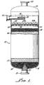
- the apparatus therein shown consists essentially of a down flow catalytic reactor 10 with its various internal parts.
- the reactor comprises a cylindrical vessel 12.
- Vessel 12 is typically constructed of corrosion resistant metal or an equivalent material such as stainless steel, ceramic or the like, and is normally insulated internally or externally for operation at elevated temperatures. While vessel 12 is substantially cylindrical in the preferred form, it can also be of a non cylindrical shape if desired.
- Vessel 12 has an outlet conduit 18 in a bottom portion 16.
- a top portion 14 is provided with a conduit 20 for convenience in filling vessel 12 with catalyst, and for routine maintenance.
- a foraminous, cone shaped cylindrical grating 22 is located immediately above outlet conduit 18 to act as a barrier to prevent the escape of solids from within vessel 12 through outlet 18 while permitting fluid product to discharge therethrough.
- a gas - liquid feed is introduced through conduit 20 into the top portion 14 of vessel 12.
- quench conduit 24 is provided which includes a sparger 26 comprising a closed pipe with two identical radial slits 28 for injecting a quench gas in two sheet like jets. Additional quench gas can be introduced into vessel 12 through conduit 20 to control temperature if desired.
- the features described in the foregoing paragraph are conventional in a great many catalytic reactors.
- the improvement of the present invention comprises a novel feed distribution system comprising a transverse partition or distribution tray 30 and a plurality of bubble cap assemblies such as shown at 32, 32A and 32B on the drawing.
- a more specific aspect the invention is directed to the bubble cap assemblies 32, which will be described in more detail later.
- distribution tray 30 is securely mounted substantially horizontally within vessel 12 by a circumferential support bracket 34.
- Distribution tray 30 is substantially vapor and liquid tight, except for the downward openings in the riser of the bubble cap assemblies 32.
- reactors suitable for use with the present invention can differ substantially in non-critically aspects from that depicted in Figure 1.
- Such reactors can, for example, contain two or more distribution tray-catalyst bed combinations, or units, which can be arranged in series or parallel relationship. It also is not essential that the catalyst bed used in accordance with this invention have layers of inert materials such as described.
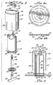
- Bubble cap assembly 100 comprises a riser 112, a bubble cap 114, spacer means 116, a retainer member 118, lock means 120, and dispersion plate 158.
- Riser 112 which is generally cylindrical in form, preferably is provided with a lower lip or extension 124 which is received within an opening 126 in a deck tray 122.
- Riser 112 may be cut from a length of tubular material or may be rolled from a length of sheet stock as desired.
- Riser 112 also includes a flange portion 128 adjacent its lower end which supports the riser on an upper surface 130 of deck plate 122. As depicted, flange 128 is formed as an integral part of riser 112. Alternatively, the flange could be in the form of a separate ring attached to the riser by press fit, shrink fit, welding or any other manner.
- Riser 112 has an inner passageway 132 which provides substantially the sole means of fluid communication across deck tray 122 through dispersion plate 158.
- Bubble cap 114 encompasses an upper end of riser 112.
- Bubble cap 114 comprises a top wall 134 terminating about its periphery in a downwardly extending skirt 136 which terminates adjacent upper surface 130 of deck tray 122.
- skirt 136 will have a plurality of slots or openings 137 for the passage of fluid therethrough.
- the function of the slots 137 is to provide a pressure drop there-across such that the liquid level in the annular space defined by cap 114 and riser 112 is higher than the liquid level on distribution tray 30.
- the higher liquid level in the annular space will offset any irregularities in liquid level on distribution tray 30 and ensure a substantially uniform gas-liquid flow through each bubble cap assembly, and substantially uniform mixing of the gas and liquid.
- Bubble cap 114 further includes a substantially centrally located aperture 138 located in top wall 134.
- Aperture 138 comprises two rectangular openings superimposed upon and at substantially right angles to one another forming an opening in the shape of a cross, that is, the central points of the two rectangular openings are coincident and preferably are on the axis of bubble cap 114.
- one of the rectangular openings is larger than the other, i.e., one has a longer length than the other opening. The function of these two openings will be described later.
- Means are provided for maintaining bubble cap 114 and riser 112 in a spaced apart relationship with one another substantially as depicted. As shown in the drawing, this means comprises a plurality of spacers 116 which typically will be fastened to the cap, riser or both. Top wall 134 of cap 114 rests on spacers 116. Spacers 116 also extend radially outwardly and maintain bubble cap 114 substantially centered with respect to riser 112.
- Means are provided for securing bubble cap assembly 100 in position on deck tray 122 in communication with opening 126.
- this means includes a retainer member 118 and lock means 120.
- Retainer member 118 is disposed within inner passageway 132.
- a lower end of retainer member 118 is provided with oppositely extending projections 140.
- Each of projections 140 is provided with an upwardly extending face portion 142 for engagement with a bottom surface 144 of deck tray 122. If the lower lip 124 of riser 112 extends below surface 144 of deck tray 122, it may be necessary to provide a notch 125 ( Figure 2) in lower lip 124 to ensure that faces 142 of retainer member 118 engages bottom surface 144 of deck 122.
- Retainer member 118 further includes an upwardly extending stem portion 146 which is received through an opening 160 of dispersion plate 158 and through the smaller of the two rectangular openings forming aperture 138 in bubble cap 114. Retainer member 118 is provided with a vertical slot 148 for receiving therethrough a substantial portion of lock means 120.
- a locking means 120 comprises two substantially parallel leg members 150 and 152 which are connected at one end by a base member 154.
- One of the leg members for example, leg member 152, is in the form of a ramp to provide a wedge means for engagement with slot 148 in retainer member 118 which extends through top wall 134 of bubble cap 114.
- Leg members 150 and 152 and base member 154 are sized for passage through the larger of the two rectangular openings forming aperture 138 in bubble cap 114.
- leg member 152 is provided with an end piece 156 which is sized to prevent passage of locking means 120 through aperture 138 during installation and removal of the bubble cap assembly.
- end piece 156 is welded or otherwise attached to the end of leg member 152. It will be apparent, however, that it could also be an integral part of leg member 152, for example, by bending the end of leg member 152 to form a comparable end portion.
- the ramp portion of leg member 152 engages slot 148 in retaining member 118 and presses against top wall 134 of bubble cap 114.
- the ramp portion acts as a wedge for tightly urging bubble cap 114, spacer means 116 and riser 112 against upper surface 130 of deck tray 122 and concurrently urging faces 142 of retainer member 118 against lower surface 144 of deck tray 122 to retain dispersion plate 158 in position.
- retainer member 118 is suspended at its lowest position with respect to bubble cap 114 by locking means 120.
- the lower end portion 140 of retainer member 118 is inclined and inserted through opening 126 of deck tray 122.
- retainer member 118 is raised and bubble cap assembly 110 clamped in position by driving the wedge portion of locking means 120 into slot 148 to the position shown in Figure 3.
- Dispersion plate 158 is provided with a centrally located opening 160 for the passage therethrough of the retainer member 118.
- Plate 158 further includes a plurality of openings 162.
- the number and size of openings 162 are such as to provide a substantial reduction in cross sectional flow area for the liquid-vapor passing through riser 112.
- the cross sectional flow area provided by openings 162 will be from 2 to 75 percent, generally from 5 to 85 percent and preferably from 10 to 40 percent of the internal cross sectional area passageway 132 of riser 112.
- openings 162 are, of course, to ensure that the two phase liquid-vapor feed entering the upper portion of riser 112 will pass in close proximity to one another through the reduced size openings to effect a shearing of the liquid by the vapor and produce a mist flow.
- openings 162 may vary.
- the openings may be round, square, rectangular or the like The best results have been obtained through the use of slots in a radial pattern as depicted.
- the slots also may be straight, forming a square or rectangular pattern.
- the width of the slot may vary depending upon numerous variables including physical properties of the liquid, gas, flow rates, temperature and permissible pressure drop among other things.
- slots 162 will have a width of from about 1/16 to 1 inch, preferably from 1/8 to 1/2 inch, and most preferably from about 3/16 to 1/4 inch for most applications wherein a liquid hydrocarbon is treated with a gaseous hydrocarbon.
- the length and number of the openings 162 will be selected to ensure a pressure drop which will both produce the desired mist flow and not be excessive for use in the selected system.
- the desired mist flow can be obtained across openings 162, which are usually selected to produce a pressure drop within the range from about 0.1 to 50 inches of water.
- a preferred pressure drop is within the range from about 0.5 to 15 inches of water and particularly in the range of from 1 to 10 inches of water with most preferred in the range of from 5 to 10 inches of water.
- the dispersion plate 158 has downwardly and outwardly projecting tab members 164 on the outer openings.
- the function of tab members 164 is to divert the mist flow radially outward from the center of dispersion plate 158 to cover a greater area of contact material.
- the inner openings 162 are not provided with such tab members. The reasons for this is to ensure that an adequate portion of the mist flow will pass downwardly and impinge upon that portion of the contact material located directly beneath the dispersion plate.
- An advantage of the present invention is that tab members 164 can readily be formed as an integral portion of dispersion plate 158. This is accomplished by not shearing off both sides of the openings 162 when those openings are formed.
- tab members could be added to plate 158 by welding, riveting, or the like; however, such fabrication methods would increase the cost without any significant added benefit.
- the range of G v / ⁇ should be in the range of from 5,000 to 30,000, and preferably from 10,000 to 20,000.
Landscapes
- Chemical & Material Sciences (AREA)
- Chemical Kinetics & Catalysis (AREA)
- Organic Chemistry (AREA)
- Physical Or Chemical Processes And Apparatus (AREA)
- Devices And Processes Conducted In The Presence Of Fluids And Solid Particles (AREA)
- Vaporization, Distillation, Condensation, Sublimation, And Cold Traps (AREA)
- Gas Separation By Absorption (AREA)
- Feeding, Discharge, Calcimining, Fusing, And Gas-Generation Devices (AREA)
- Hydrogen, Water And Hydrids (AREA)
- Medicines Containing Material From Animals Or Micro-Organisms (AREA)
- Investigating Or Analysing Biological Materials (AREA)
- Pharmaceuticals Containing Other Organic And Inorganic Compounds (AREA)
- Production Of Liquid Hydrocarbon Mixture For Refining Petroleum (AREA)
Claims (17)
- Assemblage de cloche de barbotage (32) comprenant un conduit définissant un passage (132) pour des fluides, ledit conduit comprenant une ouverture d'entrée vers le passage (132) et une ouverture de sortie depuis le passage (132), une cloche de barbotage (114) située au-dessus de l'ouverture d'entrée vers le passage (132) du conduit, ladite cloche de barbotage (114) comprenant une partie supérieure (134), une partie (136) formant jupe s'étendant vers le bas et une ouverture (138) située dans la partie supérieure (134), des moyens (116) d'espacement pour maintenir un espace entre l'ouverture d'entrée du conduit et la cloche de barbotage (114) et des moyens (120) de verrouillage pour fixer l'assemblage de cloche de barbotage (32) à un plateau de support (30), caractérisé par une plaque de dispersion (158), située dans une position adjacente à l'ouverture de sortie dudit conduit, la plaque de dispersion (158) étant traversée par plusieurs ouvertures (162), lesdites ouvertures (162) fournissant le seul moyen au fluide pour sortir dudit conduit.
- Assemblage de cloche de barbotage selon la revendication 1, caractérisé en ce que lesdites ouvertures (162) dans la plaque de dispersion (158) ont des formes de fentes allongées.
- Assemblage de cloche de barbotage selon la revendication 2, caractérisé en ce que lesdites fentes ont une largeur de 1/16 à 1 pouce.
- Assemblage de cloche de barbotage selon la revendication 2 ou 3, caractérisé en ce que le nombre et la taille desdites ouvertures (162) dans ladite plaque de dispersion (158) sont choisis pour fournir une aire transversale de flux de 2 à 80% de celle du conduit.
- Assemblage de cloche de barbotage selon les revendications 2 à 4, caractérisé en ce qu'une partie des fentes est munie d'organes formant pattes (164) adjacentes à une surface aval de la plaque de dispersion (158).
- Assemblage de cloche de barbotage selon la revendication 5, caractérisé en ce que les organes formant pattes (164) sont venus de matière avec la plaque de dispersion (158).
- Assemblage de cloche de barbotage selon l'une quelconque des revendications précédentes, caractérisé en ce que le conduit comprend un organe de canalisation ascendant (112) ayant une extrémité destinée à être située au-dessus d'une ouverture du plateau de support (30), et une extrémité opposée, les moyens (116) d'espacement étant situés en une position intermédiaire entre l'extrémité opposée de l'organe de canalisation ascendant (112) et la cloche de barbotage (114) pour maintenir un trajet d'écoulement de fluide entre ceux-ci, un organe d'arrêt (118) est disposé dans le passage (132) dans l'organe de canalisation ascendant(112), et comprend :(1) une partie d'extrémité inférieure (140) pour coopérer avec une surface inférieure du plateau de support (30),(2) une partie formant tige (146) reliée à la partie d'extrémité inférieure (140) et s'étendant vers le haut en direction de l'ouverture (138) dans la cloche de barbotage (114), et(3) une extrémité supérieure s'étendant à travers la cloche de barbotage (114),
la plaque de dispersion (158) présente une ouverture sensiblement centrale (160) pour le passage au travers de la partie formant tige (146) de l'élément d'arrêt (118), et les moyens (120) de verrouillage maintiennent la cloche de barbotage (114), les moyens (116) d'espacement et l'organe de canalisation ascendant (112), et la partie d'extrémité inférieure de l'élément d'arrêt (118) ensemble. - Assemblage selon la revendication 7, caractérisé en ce que les ouvertures (162) dans la plaque de dispersion (158) sont dimensionnées pour produire une chute de pression de 0,5 à 15 pouces d'eau.
- Assemblage selon les revendications 2 à 8, caractérisé en ce que les fentes ont une largeur de 1/8 à 1/2 pouce.
- Assemblage selon la revendication 7, caractérisé en ce que l'aire transversale de flux des ouvertures (162) dans la plaque de dispersion (158) représente 10 à 40% de la surface de flux de l'organe de canalisation ascendant.
- Assemblage selon la revendication 10, caractérisé en ce que les ouvertures (162) dans la plaque de dispersion (158) sont allongées et s'étendent sensiblement radialement autour du centre de l'organe de canalisation ascendant (112).
- Assemblage selon la revendication 11, caractérisé en ce que lesdites encoches ont une largeur de 3/16 à 1/4 de pouce, et la longueur et le nombre d'encoches fournit une chute de pression en traversant la plaque de dispersion (158) de 1 à 10 pouces d'eau.
- Procédé pour produire un flux d'une dispersion de gaz et de liquide, comprenant l'utilisation de l'assemblage de cloche de barbotage de la revendication 1 ou 2.
- Procédé selon la revendication 13, caractérisé en ce que le nombre et la taille des ouvertures dans la plaque de dispersion (158), et le débit de liquide et de gaz produisent une chute de pression de 3 à 20 pouces d'eau.
- Procédé selon la revendication 14, caractérisé en ce qu'on fait circuler le gaz et le liquide à travers la plaque de dispersion (158) à une vitesse suffisante pour produire une chute de pression de 5 à 10 pouces d'eau.
- Procédé selon la revendication 13, caractérisé en ce que le Gv/λ est compris dans la plage s'étendant d'environ 5000 à 30000, où Gv et la vitesse moyenne de la vapeur et λ et

- Procédé selon la revendication 15, caractérisé en ce que Rev est supérieur à 1,2x10⁶/Rel 0,8, dans lequel Rev et Rel sont respectivement les nombres de Reynolds du gaz et du liquide.
Applications Claiming Priority (3)
| Application Number | Priority Date | Filing Date | Title |
|---|---|---|---|
| US07/710,352 US5158714A (en) | 1991-05-30 | 1991-05-30 | Vapor-liquid distribution method and apparatus |
| PCT/US1992/002584 WO1992021418A1 (fr) | 1991-05-30 | 1992-03-30 | Procede et appareil de distribution d'une phase mixte vapeur-liquide |
| US710352 | 1996-09-17 |
Publications (2)
| Publication Number | Publication Date |
|---|---|
| EP0641237A1 EP0641237A1 (fr) | 1995-03-08 |
| EP0641237B1 true EP0641237B1 (fr) | 1997-08-13 |
Family
ID=24853676
Family Applications (1)
| Application Number | Title | Priority Date | Filing Date |
|---|---|---|---|
| EP92913782A Expired - Lifetime EP0641237B1 (fr) | 1991-05-30 | 1992-03-30 | Procede et appareil de distribution d'une phase mixte vapeur-liquide |
Country Status (12)
| Country | Link |
|---|---|
| US (1) | US5158714A (fr) |
| EP (1) | EP0641237B1 (fr) |
| JP (1) | JP3255918B2 (fr) |
| AT (1) | ATE156721T1 (fr) |
| AU (1) | AU2183292A (fr) |
| CZ (1) | CZ251693A3 (fr) |
| DE (1) | DE69221639T2 (fr) |
| ES (1) | ES2107541T3 (fr) |
| FI (1) | FI105777B (fr) |
| OA (1) | OA09825A (fr) |
| SK (1) | SK131493A3 (fr) |
| WO (1) | WO1992021418A1 (fr) |
Families Citing this family (40)
| Publication number | Priority date | Publication date | Assignee | Title |
|---|---|---|---|---|
| SE9200183L (sv) * | 1992-01-23 | 1993-07-24 | Kamyr Ab | Avskiljningsanordning samt foerfarande |
| US6098965A (en) * | 1996-06-04 | 2000-08-08 | Fluor Corporation | Reactor distribution apparatus and quench zone mixing apparatus |
| US5989502A (en) * | 1996-06-04 | 1999-11-23 | Fluor Corporation | Reactor distribution apparatus and quench zone mixing apparatus |
| US5837208A (en) * | 1996-06-12 | 1998-11-17 | Uop | Hydroprocessing reactor mixer/distributor |
| DE69734344T3 (de) * | 1996-12-19 | 2011-04-21 | Haldor Topsoe A/S | Flüssigkeitsverteiler für Abwärtsströmung zweier Phasen |
| US7125006B2 (en) * | 2000-12-21 | 2006-10-24 | Fluor Technologies Corporation | Methods and apparatus for mixing fluids |
| US20020175427A1 (en) * | 2000-12-21 | 2002-11-28 | Fluor Corporation | Methods and apparatus for mixing fluids |
| WO2002085504A1 (fr) * | 2001-04-24 | 2002-10-31 | Fluor Corporation | Procedes et appareils de melange de fluides |
| US6769672B2 (en) * | 2002-10-08 | 2004-08-03 | Uop Llc | Two-phase distribution apparatus and process |
| US6832754B2 (en) * | 2003-03-18 | 2004-12-21 | Alan Cross | Gas-liquid contactor |
| US7722832B2 (en) * | 2003-03-25 | 2010-05-25 | Crystaphase International, Inc. | Separation method and assembly for process streams in component separation units |
| AU2004313651B2 (en) * | 2004-01-15 | 2010-02-11 | Haldor Topsoe A/S | Vapour-liquid distribution tray |
| US7506861B2 (en) * | 2005-01-21 | 2009-03-24 | Morten Muller Ltd. Aps | Distribution device for two-phase concurrent downflow vessels |
| BRPI0703901B1 (pt) * | 2007-10-10 | 2016-03-22 | Petróleo Brasileiro S A Petrobras | dispositivo e processo para distribuição de cargas mistas sobre leitos fixos de catalisador em reatores de fluxo descendente |
| BRPI0704849B1 (pt) * | 2007-12-13 | 2016-03-22 | Petróleo Brasileiro S A Petrobras | bico distribuidor de carga bifásica para reatores de leito fixo |
| PL2078552T3 (pl) | 2008-01-09 | 2014-11-28 | Haldor Topsoe As | Urządzenie do rozprowadzania pary-cieczy |
| US7901641B2 (en) * | 2008-07-22 | 2011-03-08 | Uop Llc | Sprayer for at least one fluid |
| US8372354B2 (en) | 2010-07-19 | 2013-02-12 | Chevron U.S.A. Inc. | Multiphase contact and distribution apparatus for hydroprocessing |
| US8202498B2 (en) | 2010-07-19 | 2012-06-19 | Chevron U.S.A. Inc. | Multiphase contact and distribution apparatus for hydroprocessing |
| FR2964325B1 (fr) * | 2010-09-03 | 2013-01-04 | IFP Energies Nouvelles | Dispositif de distribution d'un melange polyphasique comportant un plateau brise-jet avec element de separation |
| US8517353B2 (en) | 2010-09-27 | 2013-08-27 | Uop Llc | Apparatus and process for distributing vapor and liquid phases |
| CN102451648B (zh) * | 2010-10-25 | 2015-01-14 | 中国石油化工股份有限公司 | 气液分配器 |
| ES2617581T3 (es) | 2011-07-29 | 2017-06-19 | Saudi Arabian Oil Company | Materia prima enriquecida en hidrógeno para un proceso de craqueo catalítico fluidizado |
| FR2980720B1 (fr) * | 2011-09-30 | 2013-09-06 | Ifp Energies Now | Plateau distributeur pour la distribution d'un melange polyphasique avec cheminees inclinees en peripherie. |
| KR101532187B1 (ko) | 2011-11-21 | 2015-06-26 | 사우디 아라비안 오일 컴퍼니 | 슬러리층 수소화처리 및 시스템 |
| US9327250B2 (en) * | 2014-05-07 | 2016-05-03 | The Babcock & Wilcox Company | Fluidizing nozzle or bubble cap assembly for air distribution grid |
| KR101977810B1 (ko) | 2015-08-28 | 2019-05-13 | 주식회사 엘지화학 | 분배기 및 이를 포함하는 하강류 촉매 반응기 |
| KR102001608B1 (ko) * | 2015-08-28 | 2019-07-18 | 주식회사 엘지화학 | 분배기 및 이를 포함하는 하강류 촉매 반응기 |
| KR102033380B1 (ko) * | 2015-09-07 | 2019-10-17 | 주식회사 엘지화학 | 고정층 기액 수소화 반응기 및 이를 포함하는 네오펜틸 글리콜의 제조방법 |
| US20180215683A1 (en) | 2017-01-27 | 2018-08-02 | Saudi Arabian Oil Company | Isomerization process using feedstock containing dissolved hydrogen |
| US11298669B2 (en) | 2017-12-21 | 2022-04-12 | Uop Llc | Scale collection device for downflow reactors |
| US11224849B2 (en) * | 2017-12-21 | 2022-01-18 | Uop Llc | Scale collection device for downflow reactors |
| SA118400251B1 (ar) * | 2018-02-23 | 2021-12-06 | انديان اويل كوربوريشن ليمتد | توزيع مُحسّن لخليط مائع متعدد الأطوار |
| JP7044629B2 (ja) * | 2018-05-18 | 2022-03-30 | 株式会社堀場エステック | 流体制御装置、及び、流量比率制御装置 |
| JP7068062B2 (ja) * | 2018-06-18 | 2022-05-16 | 株式会社堀場製作所 | 流体制御装置、及び、流量比率制御装置 |
| US11312912B2 (en) | 2019-05-29 | 2022-04-26 | Saudi Arabian Oil Company | Hydrogen-enhanced delayed coking process |
| US11084991B2 (en) | 2019-06-25 | 2021-08-10 | Saudi Arabian Oil Company | Two-phase moving bed reactor utilizing hydrogen-enriched feed |
| WO2021163352A1 (fr) | 2020-02-11 | 2021-08-19 | Saudi Arabian Oil Company | Procédés et systèmes de production pétrochimique intégrant une hydrogénation profonde de distillats |
| US11707696B2 (en) * | 2020-08-10 | 2023-07-25 | Gti Solutions International Llc | Liquid distribution systems and methods |
| KR102609566B1 (ko) * | 2022-07-26 | 2023-12-04 | 한국생산기술연구원 | 브림을 포함하는 버블캡 어셈블리 |
Family Cites Families (14)
| Publication number | Priority date | Publication date | Assignee | Title |
|---|---|---|---|---|
| US1915746A (en) * | 1930-05-19 | 1933-06-27 | Jenkins Petroleum Process Comp | Dephlegmator or bubble tower |
| US2710177A (en) * | 1952-04-07 | 1955-06-07 | Braun & Co C F | Bubble cap assembly with choke |
| US2778621A (en) * | 1953-12-08 | 1957-01-22 | Standard Oil Co | Entrainment-obviating bubble cap |
| GB788075A (en) * | 1955-04-29 | 1957-12-23 | Monsanto Chemicals | Fractionating trays |
| US3218249A (en) * | 1964-03-30 | 1965-11-16 | Union Oil Co | Vapor-liquid distribution method and apparatus for the conversion of hydrocarbons |
| US3685971A (en) * | 1970-07-06 | 1972-08-22 | Universal Oil Prod Co | Flow distributing apparatus |
| DE2301644C2 (de) * | 1973-01-13 | 1974-07-18 | Friedrich Uhde Gmbh, 4600 Dortmund | Vorrichtung zur Herstellung eines homogenen Gasgemisches |
| SU652948A1 (ru) * | 1977-12-12 | 1979-03-25 | Предприятие П/Я Р-6603 | Массообменный аппарат |
| US4140625A (en) * | 1977-12-19 | 1979-02-20 | Uop Inc. | Mixed-phase distributor for fixed-bed catalytic reaction chambers |
| US4313908A (en) * | 1980-10-20 | 1982-02-02 | Exxon Research & Engineering Co. | Catalytic reactor having bed bypass |
| US4836989A (en) * | 1987-07-02 | 1989-06-06 | Mobil Oil Corporation | Distribution system for downflow reactors |
| US4960571A (en) * | 1988-12-14 | 1990-10-02 | Exxon Research And Engineering Company | Quench assembly design |
| DD291703A5 (de) * | 1990-01-26 | 1991-07-11 | Technische Hochschule Zittau,De | Duesenboden |
| US5045247A (en) * | 1990-03-30 | 1991-09-03 | Union Oil Company Of California | Bubble cap assembly |
-
1991
- 1991-05-30 US US07/710,352 patent/US5158714A/en not_active Expired - Lifetime
-
1992
- 1992-03-30 AT AT92913782T patent/ATE156721T1/de not_active IP Right Cessation
- 1992-03-30 DE DE69221639T patent/DE69221639T2/de not_active Expired - Fee Related
- 1992-03-30 CZ CS932516A patent/CZ251693A3/cs unknown
- 1992-03-30 AU AU21832/92A patent/AU2183292A/en not_active Abandoned
- 1992-03-30 SK SK1314-93A patent/SK131493A3/sk unknown
- 1992-03-30 WO PCT/US1992/002584 patent/WO1992021418A1/fr not_active Ceased
- 1992-03-30 JP JP50038793A patent/JP3255918B2/ja not_active Expired - Lifetime
- 1992-03-30 ES ES92913782T patent/ES2107541T3/es not_active Expired - Lifetime
- 1992-03-30 EP EP92913782A patent/EP0641237B1/fr not_active Expired - Lifetime
-
1993
- 1993-11-22 FI FI935173A patent/FI105777B/fi not_active IP Right Cessation
- 1993-11-30 OA OA60443A patent/OA09825A/xx unknown
Also Published As
| Publication number | Publication date |
|---|---|
| ATE156721T1 (de) | 1997-08-15 |
| JPH06508063A (ja) | 1994-09-14 |
| OA09825A (en) | 1994-04-15 |
| FI935173L (fi) | 1993-11-30 |
| AU2183292A (en) | 1993-01-08 |
| SK131493A3 (en) | 1994-07-06 |
| DE69221639T2 (de) | 1998-02-12 |
| FI935173A0 (fi) | 1993-11-22 |
| FI105777B (fi) | 2000-10-13 |
| WO1992021418A1 (fr) | 1992-12-10 |
| EP0641237A1 (fr) | 1995-03-08 |
| ES2107541T3 (es) | 1997-12-01 |
| US5158714A (en) | 1992-10-27 |
| CZ251693A3 (en) | 1994-04-13 |
| DE69221639D1 (de) | 1997-09-18 |
| JP3255918B2 (ja) | 2002-02-12 |
Similar Documents
| Publication | Publication Date | Title |
|---|---|---|
| EP0641237B1 (fr) | Procede et appareil de distribution d'une phase mixte vapeur-liquide | |
| US5989502A (en) | Reactor distribution apparatus and quench zone mixing apparatus | |
| US5837208A (en) | Hydroprocessing reactor mixer/distributor | |
| US6338828B1 (en) | Reactor distribution apparatus and quench zone mixing apparatus | |
| US4233269A (en) | Gas liquid distributor | |
| US7070745B2 (en) | Multiple bed downflow reactor | |
| KR970006666B1 (ko) | 다운플로우 반응기용 분배 시스템 | |
| US5232283A (en) | Apparatus for mixing concurrently, downwardly flowing fluids | |
| US3218249A (en) | Vapor-liquid distribution method and apparatus for the conversion of hydrocarbons | |
| US20020172632A1 (en) | Quench box for a multi-bed, mixed-phase cocurrent downflow fixed-bed reactor | |
| US4138327A (en) | Vapor/liquid distributor for fixed-bed catalytic reaction chambers | |
| US7651076B2 (en) | Device for distributing a poly-phase mixture on a granular solid bed comprising a porous anti-splash nozzle element with flanges | |
| US3652451A (en) | Fluid distribution for fluid-solids contacting chambers | |
| EP3658271B1 (fr) | Appareil de mise en contact de fluide dans un réservoir à écoulement descendant | |
| EP3658267B1 (fr) | Procédés de mise en contact de fluides dans une cuve à courant descendant | |
| CA3071250C (fr) | Procedes et appareil de mise en contact de fluide dans un reservoir a ecoulement descendant | |
| US20120116136A1 (en) | Device for distributing a polyphase mixture comprising a jet breaker tray with a separating element |
Legal Events
| Date | Code | Title | Description |
|---|---|---|---|
| PUAI | Public reference made under article 153(3) epc to a published international application that has entered the european phase |
Free format text: ORIGINAL CODE: 0009012 |
|
| 17P | Request for examination filed |
Effective date: 19931223 |
|
| AK | Designated contracting states |
Kind code of ref document: A1 Designated state(s): AT BE DE ES FR GB IT NL |
|
| 17Q | First examination report despatched |
Effective date: 19950410 |
|
| GRAG | Despatch of communication of intention to grant |
Free format text: ORIGINAL CODE: EPIDOS AGRA |
|
| GRAH | Despatch of communication of intention to grant a patent |
Free format text: ORIGINAL CODE: EPIDOS IGRA |
|
| RAP1 | Party data changed (applicant data changed or rights of an application transferred) |
Owner name: UOP |
|
| GRAH | Despatch of communication of intention to grant a patent |
Free format text: ORIGINAL CODE: EPIDOS IGRA |
|
| GRAA | (expected) grant |
Free format text: ORIGINAL CODE: 0009210 |
|
| AK | Designated contracting states |
Kind code of ref document: B1 Designated state(s): AT BE DE ES FR GB IT NL |
|
| PG25 | Lapsed in a contracting state [announced via postgrant information from national office to epo] |
Ref country code: AT Effective date: 19970813 |
|
| REF | Corresponds to: |
Ref document number: 156721 Country of ref document: AT Date of ref document: 19970815 Kind code of ref document: T |
|
| ITF | It: translation for a ep patent filed | ||
| REF | Corresponds to: |
Ref document number: 69221639 Country of ref document: DE Date of ref document: 19970918 |
|
| ET | Fr: translation filed | ||
| REG | Reference to a national code |
Ref country code: ES Ref legal event code: FG2A Ref document number: 2107541 Country of ref document: ES Kind code of ref document: T3 |
|
| PLBE | No opposition filed within time limit |
Free format text: ORIGINAL CODE: 0009261 |
|
| STAA | Information on the status of an ep patent application or granted ep patent |
Free format text: STATUS: NO OPPOSITION FILED WITHIN TIME LIMIT |
|
| 26N | No opposition filed | ||
| REG | Reference to a national code |
Ref country code: GB Ref legal event code: IF02 |
|
| PGFP | Annual fee paid to national office [announced via postgrant information from national office to epo] |
Ref country code: DE Payment date: 20020320 Year of fee payment: 11 |
|
| PGFP | Annual fee paid to national office [announced via postgrant information from national office to epo] |
Ref country code: NL Payment date: 20030305 Year of fee payment: 12 |
|
| PG25 | Lapsed in a contracting state [announced via postgrant information from national office to epo] |
Ref country code: DE Free format text: LAPSE BECAUSE OF NON-PAYMENT OF DUE FEES Effective date: 20031001 |
|
| PG25 | Lapsed in a contracting state [announced via postgrant information from national office to epo] |
Ref country code: NL Free format text: LAPSE BECAUSE OF NON-PAYMENT OF DUE FEES Effective date: 20041001 |
|
| NLV4 | Nl: lapsed or anulled due to non-payment of the annual fee |
Effective date: 20041001 |
|
| PGFP | Annual fee paid to national office [announced via postgrant information from national office to epo] |
Ref country code: GB Payment date: 20090206 Year of fee payment: 18 |
|
| PGFP | Annual fee paid to national office [announced via postgrant information from national office to epo] |
Ref country code: BE Payment date: 20090429 Year of fee payment: 18 |
|
| PGFP | Annual fee paid to national office [announced via postgrant information from national office to epo] |
Ref country code: FR Payment date: 20090306 Year of fee payment: 18 |
|
| PGFP | Annual fee paid to national office [announced via postgrant information from national office to epo] |
Ref country code: ES Payment date: 20100323 Year of fee payment: 19 |
|
| BERE | Be: lapsed |
Owner name: *UOP Effective date: 20100331 |
|
| GBPC | Gb: european patent ceased through non-payment of renewal fee |
Effective date: 20100330 |
|
| REG | Reference to a national code |
Ref country code: FR Ref legal event code: ST Effective date: 20101130 |
|
| PG25 | Lapsed in a contracting state [announced via postgrant information from national office to epo] |
Ref country code: FR Free format text: LAPSE BECAUSE OF NON-PAYMENT OF DUE FEES Effective date: 20100331 |
|
| PG25 | Lapsed in a contracting state [announced via postgrant information from national office to epo] |
Ref country code: BE Free format text: LAPSE BECAUSE OF NON-PAYMENT OF DUE FEES Effective date: 20100331 |
|
| PG25 | Lapsed in a contracting state [announced via postgrant information from national office to epo] |
Ref country code: GB Free format text: LAPSE BECAUSE OF NON-PAYMENT OF DUE FEES Effective date: 20100330 |
|
| PGFP | Annual fee paid to national office [announced via postgrant information from national office to epo] |
Ref country code: IT Payment date: 20110326 Year of fee payment: 20 |
|
| REG | Reference to a national code |
Ref country code: ES Ref legal event code: FD2A Effective date: 20120424 |
|
| PG25 | Lapsed in a contracting state [announced via postgrant information from national office to epo] |
Ref country code: ES Free format text: LAPSE BECAUSE OF NON-PAYMENT OF DUE FEES Effective date: 20110331 |