EP0640987A1 - Debris filters with flow bypass for boiling water reactors - Google Patents
Debris filters with flow bypass for boiling water reactors Download PDFInfo
- Publication number
- EP0640987A1 EP0640987A1 EP94305688A EP94305688A EP0640987A1 EP 0640987 A1 EP0640987 A1 EP 0640987A1 EP 94305688 A EP94305688 A EP 94305688A EP 94305688 A EP94305688 A EP 94305688A EP 0640987 A1 EP0640987 A1 EP 0640987A1
- Authority
- EP
- European Patent Office
- Prior art keywords
- plenum
- debris
- fuel
- flow
- means defining
- Prior art date
- Legal status (The legal status is an assumption and is not a legal conclusion. Google has not performed a legal analysis and makes no representation as to the accuracy of the status listed.)
- Withdrawn
Links
Images


Classifications
-
- G—PHYSICS
- G21—NUCLEAR PHYSICS; NUCLEAR ENGINEERING
- G21C—NUCLEAR REACTORS
- G21C3/00—Reactor fuel elements and their assemblies; Selection of substances for use as reactor fuel elements
- G21C3/30—Assemblies of a number of fuel elements in the form of a rigid unit
- G21C3/32—Bundles of parallel pin-, rod-, or tube-shaped fuel elements
- G21C3/3206—Means associated with the fuel bundle for filtering the coolant, e.g. nozzles, grids
-
- Y—GENERAL TAGGING OF NEW TECHNOLOGICAL DEVELOPMENTS; GENERAL TAGGING OF CROSS-SECTIONAL TECHNOLOGIES SPANNING OVER SEVERAL SECTIONS OF THE IPC; TECHNICAL SUBJECTS COVERED BY FORMER USPC CROSS-REFERENCE ART COLLECTIONS [XRACs] AND DIGESTS
- Y02—TECHNOLOGIES OR APPLICATIONS FOR MITIGATION OR ADAPTATION AGAINST CLIMATE CHANGE
- Y02E—REDUCTION OF GREENHOUSE GAS [GHG] EMISSIONS, RELATED TO ENERGY GENERATION, TRANSMISSION OR DISTRIBUTION
- Y02E30/00—Energy generation of nuclear origin
- Y02E30/30—Nuclear fission reactors
Definitions
- a debris catching arrangement for incorporation within a flow plenum up stream of the rod supporting grid of the lower tie plate assembly.
- the disclosed debris catching designs include the two phase separation of the heavier debris from the lighter transporting water by flow direction (momentum) change with the debris directed and detoured to a trapping structure. This allows for partial flow bypass around the trapping structure, to eliminate potential flow blockage concerns.
- Boiling water nuclear reactors operate for many years. Commencing with their initial construction and through their service lives, these reactors may accumulate debris in their closed circulation moderator systems. This debris can become an operating hazard if the debris is allowed to enter into the fuel bundle containing core region having the heat generating fuel rods.
- a summary of reactor construction as it relates to the accumulation of debris needs first to be given. Thereafter, fuel bundle construction will be set forth. Emphasis will be given to the need to preserve substantially unchanged the regions of pressure drop along the flow paths. Thereafter, the effects caused by debris entering into the fuel rod region of the fuel bundles will be summarized.
- Boiling water nuclear reactor construction can be simply summarized for purposes of understanding the debris entrainment problem.
- Such nuclear reactors are provided with a large, central core. Liquid water coolant/moderator flow enters the core from the bottom and exits the core as a water steam mixture from the top.
- the core includes many side-by-side fuel bundles. Water is introduced into each fuel bundle through a fuel bundle support casting from a high pressure plenum which is situated below the core. Water passes in a distributed flow through the individual fuel bundles, is heated to generate steam, and exits the upper portion of the core as a two phase water steam mixture from which the steam is extracted for the generation of electricity.
- the core support castings and fuel bundle inlets are a source of pressure loss in the circulation of water through the core. This pressure loss assures the substantially even distribution of flow across the individual fuel bundles of the reactor core. When it is remembered that there are as many as 750 individual fuel bundles in a reactor core, it can be appreciated that assurance of the uniformity of flow distribution is important. To interfere with the pressure drop of the fuel bundle flow paths could effect the overall distribution of coolant/moderator within the fuel bundles of the reactor core.
- the fuel bundles for a boiling water nuclear reactor include a fuel rod supporting lower tie plate assembly, which lower tie plate assembly is a cast structure.
- the lower tie plate assembly includes at its lowest point a downward protruding bail covering an inlet nozzle.
- This inlet nozzle includes entry to an enlarged flow volume or tie plate plenum within the lower tie plate.
- At the upper end of the flow volume there is located a rod supporting grid.
- the rod supporting grid has two purposes. First, the rod supporting grid provides the mechanical support connection for the weight of the individual fuel rods to be transmitted through the entire lower tie plate to the fuel support casting. Secondly, the rod supporting grid provides a flow path for liquid water moderator into the fuel bundle for passage between the side-by-side supported fuel rods.
- each fuel bundle includes a matrix of upstanding fuel rods -- sealed tubes each containing fissionable material which when undergoing nuclear reaction produce the power generating steam.
- the matrix of upstanding fuel rods includes at the upper end a so-called upper tie plate.
- This upper tie plate holds at least some of the fuel rods in vertical side-by-side alignment.
- Some of the fuel rods are attached to both the upper and lower tie plates.
- water rods for improvement of the water moderator to fuel ratio, particularly in the upper, highest void fraction region of the fuel bundle.
- Fuel bundles also include about seven fuel rod spacers at varying elevations along the length of the fuel bundle. These spacers are required because the fuel rods are long (about 160 inches) and slender (about 0.4 to 0.5 inches in diameter), and could come into abrading contact under the dynamics of fluid flow and nuclear power generation within the fuel bundles.
- the spacers provide appropriate restraints for each fuel rod at their respective elevations and thus prevent abrading contact between the fuel rods and maintain the fuel rods at uniform spacing relative to one another along the length of the fuel bundle for optimum performance. As will hereafter be developed, these spacers are sites where debris can be trapped and damage the fuel rods.
- Each fuel bundle is surrounded by a channel.
- This channel causes water flowing between the tie plates to be restricted to only one bundle in an isolated flow path between the tie plates.
- the channel also serves to separate the steam generating flow path through the fuel bundles from the surrounding core bypass region, this region being utilized for the penetration of the control rods.
- the water in the bypass region also provides neutron moderation.
- the rod supporting grid of the fuel bundle acts as a strainer. Debris exceeding the dimension of grid passageways cannot pass through to the fuel bundles. However, it has been found that debris -- especially debris with "sail areas" --such as metal shavings, wire and the like -- move past the lower rod supporting grid and can become lodged between the fuel rods and spacers.
- the lower tie plate is modified with serpentine path -- almost in the form of a chevron. Overlying this construction there are placed rod supporting bars so that the weight of the rods does not crush the underlying serpentine path.
- debris catching arrangements are disclosed for incorporation within the flow plenum upstream or below the rod supporting grid of the lower tie plate assembly.
- the device is preferably placed within the lower tie plate flow plenum between the fuel bundle inlet orifice and the rod supporting grid structure supporting the fuel rods; alternate placement can include any inlet channel upstream of the fuel rods including the fuel support casting.
- the disclosed debris catching designs includes strainer structures defining spatially separated straining or obstructing layers imparting to the fluid in the plenum a circuitous flow path. This circuitous flow path causes the two phase separation of the heavier debris from the lighter transporting water by flow direction (momentum) change with the debris directed and detoured to a trapping structure.
- a strainer structure is provided in the plenum that does not constitute a continuum of fine structure across the strained plenum which might become clogged to the extend that overall flow is restricted; spatial separation exists in between the disclosed strainer structures.
- the straining structure is positioned so that eventual trapping of the debris occurs upon cessation of flow so that with removal of the plenum from the reactor, such as removal of the fuel bundle, the debris is likewise removed.
- Embodiments are disclosed which include swirling deflection, cone deflection, and strainer structure deflection of debris.
- Control rod drive housing H has fuel support casting C supported thereon.
- Fuel support casting C includes arm 16 which orients casting C with respect to pin 14 in core plate P.
- Core plate P divides high pressure lower plenum L from core R, preserving the necessary pressure differential barrier to cause the controlled circulation within the many individual fuel bundles of the reactor.
- Fuel support casting C includes four apertures 20 onto which four fuel bundles B at their respective lower tie plate assemblies T are placed. Each lower tie plate assembly T is disposed to cause its inlet nozzle N to communicate to one of the apertures 20 of the fuel support casting.
- Fuel support casting C also includes apertures through which control rods 22 penetrate to the interstices of the four fuel bundles sitting on top of the fuel support casting C. Since the action of the control rods is not important with respect to this invention, further discussion of this aspect of the reactor will not be included.
- Each fuel bundle includes a plurality of upstanding fuel rods 42 surrounded by a channel 44.
- Spacers 46 surround the fuel rods 42 discretely at several elevations and constitute locations where debris can be trapped, dynamically fretted by the passing coolant, and cause damage to fuel rods 42. Accordingly, and in this disclosure, the filter of this invention is located in any of the illustrated plenums to the rod supporting grid G of the lower tie plate (See Figs. 2, 3 and 4), or in the fuel support casting C.
- the debris catchers of this invention will be illustrated with location in the lower tie plate flow plenum between the inlet orifice or nozzle N and the rod supporting grid G.
- such structure must be capable of trapping particles small enough to be entrained but large enough to enter through the lower tie plate grid G and in between the fuel rods 42.
- Such a structure must be structurally sound and especially avoid any failure resulting in loose parts. It is desired that the structure trap and retain debris particles. At the same time, adverse flow conditions into the fuel bundle should not be generated.
- the filter should be such that it is not possible under any circumstances for the filter to become clogged and cause appreciable obstruction to the total flow into the fuel bundle B. Accordingly, and in the description of the specific embodiments that follow it will be seen that we utilize a filter structure that does not constitute a continuum of structure across the particular flow plenum being utilized. In each case -- assuming that the perforate portions of the filter become complete clogged -- it will be seen that unobstructed water coolant flow paths are preserved to the fuel rods.
- FIG. 2 a side elevation section schematic of a lower tie plate assembly T is shown.
- This lower tie plate includes four walls 52 defining a substantially square volume with tapered substantially conical wall 54 truncated at inlet nozzle N.
- Nozzle N includes a bail 60 over the nozzle forming the lower most structure of the fuel bundle.
- Ring 70 fastens interiorly of plenum P surrounding nozzle N and projects upwardly into the volume of plenum P. As will be realized hereafter, ring 70 forms between the inside of conical wall 54 and the outside surface of ring 70 a trap for debris.
- static swirl vane 80 located above or preferably within nozzle N is static swirl vane 80.
- Swirl vane 80 imparts an upwardly spiralling flow to coolant flowing through nozzle N into plenum P. Such spiral flow classifies heavier debris to the outside of ring 70 with the lighter coolant flowing upwardly through rod supporting grid G.
- mesh pick off filter 90 including horizontal portion 92 and downward depending ring 94 is placed centrally of the structure.
- the structure is perforate for allowing fluid flow through the mesh pick off structure; it will be understood that portions of this structure can be solid if desired.
- Water coolant including debris enters nozzle N and has a swirling motion imparted by a static swirl vane 60. Above the static swirl vane there is an open central flow path. Heavier debris --typically metal particles having 8 to 10 times the density of water -- are classified to the exterior of plenum P and trapped -- either by ring 70 or overlying mesh pick off filter 90. Debris is retained at these locations. At the same time, the open central flow path is not obstructed by a continuum of filter structure. Obstruction of the filter structure causing impeding of flow to the fuel rods 42 cannot occur.
- a structure similar to Fig. 2 is illustrated with the exception of cone deflector 100.
- This deflector peripherally diverts fluid to the plenum periphery at the cone 100.
- This cone can be constructed of mesh and/or solid material.
- Cone 100 extends beyond ring 70 and terminates in depending mesh ring 102. Depending mesh ring 102 is outside of ring 70.
- FIG. 4 a structure similar to that illustrated in Figs. 2 and 3 is illustrated in which upper filter layer 124 and lower filter layer 114 impart the circuitous flow path to the passing fluid.
- Lower filter structure 114 includes cone filter 110 having a solid central ring 11 to define a central flow path.
- a peripherally sloping perforate cone 110 truncated at the central flow paths extends to perforate ring 113.
- Upper filter layer 124 consists of peripheral annular perforate filter section 120 and central inverted conical basket 122.
- Conical basket 122 includes an inverted perforate cone section 126 and a depending perforate ring section 127.
- the disclosed design includes offset over-under placement of layered traps for debris particles. At the same time, open flow passages are preserved so that complete debris or corrosion clogging of the filter cannot occur.
- the sloped profile of the filter assists migration of the trapped debris to the collecting corners of the upper filter layer 124. Debris falling from these upper layer 124 corners is either trapped by lower filter layer 114 or optional ring 70.
Abstract
In a boiling water nuclear reactor fuel bundle (B), a debris catching arrangement is disclosed for incorporation within the flow plenum up stream or below the rod supporting grid (G) of the lower tie plate assembly (T). The device is preferably placed within the lower tie plate flow plenum between the fuel bundle inlet and the rod supporting grid structure (G) supporting the fuel rods (42); alternate placement can include any inlet channel upstream of the fuel rods (42) including the fuel support casting (C). The disclosed debris catching designs include strainer structures defining spatially separated straining or obstructing layers imparting to the fluid in the plenum a circuitous flow path. This circuitous flow path causes the two phase separation of the heavier debris from the lighter transporting water by flow direction change with the debris directed and detoured to a trapping structure. Further, a strainer structure is provided in the plenum that does not constitute a continuum of fine structure across the strained plenum which might become clogged to the extend that overall flow is restricted. The strainer structure is positioned so that eventual trapping of the debris occurs upon cessation of flow so that with removal of the plenum from the reactor, such as removal of the fuel bundle, the debris is likewise removed. Embodiments are disclosed which include swirling deflection, cone deflection, and strainer structure deflection of debris.
Description
- In a boiling water nuclear reactor fuel bundle, a debris catching arrangement is disclosed for incorporation within a flow plenum up stream of the rod supporting grid of the lower tie plate assembly. The disclosed debris catching designs include the two phase separation of the heavier debris from the lighter transporting water by flow direction (momentum) change with the debris directed and detoured to a trapping structure. This allows for partial flow bypass around the trapping structure, to eliminate potential flow blockage concerns.
- Boiling water nuclear reactors operate for many years. Commencing with their initial construction and through their service lives, these reactors may accumulate debris in their closed circulation moderator systems. This debris can become an operating hazard if the debris is allowed to enter into the fuel bundle containing core region having the heat generating fuel rods. In order to understand this problem, a summary of reactor construction as it relates to the accumulation of debris needs first to be given. Thereafter, fuel bundle construction will be set forth. Emphasis will be given to the need to preserve substantially unchanged the regions of pressure drop along the flow paths. Thereafter, the effects caused by debris entering into the fuel rod region of the fuel bundles will be summarized.
- Boiling water nuclear reactor construction can be simply summarized for purposes of understanding the debris entrainment problem. Such nuclear reactors are provided with a large, central core. Liquid water coolant/moderator flow enters the core from the bottom and exits the core as a water steam mixture from the top.
- The core includes many side-by-side fuel bundles. Water is introduced into each fuel bundle through a fuel bundle support casting from a high pressure plenum which is situated below the core. Water passes in a distributed flow through the individual fuel bundles, is heated to generate steam, and exits the upper portion of the core as a two phase water steam mixture from which the steam is extracted for the generation of electricity.
- The core support castings and fuel bundle inlets are a source of pressure loss in the circulation of water through the core. This pressure loss assures the substantially even distribution of flow across the individual fuel bundles of the reactor core. When it is remembered that there are as many as 750 individual fuel bundles in a reactor core, it can be appreciated that assurance of the uniformity of flow distribution is important. To interfere with the pressure drop of the fuel bundle flow paths could effect the overall distribution of coolant/moderator within the fuel bundles of the reactor core.
- Having set forth the construction of the boiling water nuclear reactor in so far as is appropriate, attention can now be directed to the construction of the fuel bundles themselves.
- The fuel bundles for a boiling water nuclear reactor include a fuel rod supporting lower tie plate assembly, which lower tie plate assembly is a cast structure. The lower tie plate assembly includes at its lowest point a downward protruding bail covering an inlet nozzle. This inlet nozzle includes entry to an enlarged flow volume or tie plate plenum within the lower tie plate. At the upper end of the flow volume, there is located a rod supporting grid.
- The rod supporting grid has two purposes. First, the rod supporting grid provides the mechanical support connection for the weight of the individual fuel rods to be transmitted through the entire lower tie plate to the fuel support casting. Secondly, the rod supporting grid provides a flow path for liquid water moderator into the fuel bundle for passage between the side-by-side supported fuel rods.
- Above the lower tie plate, each fuel bundle includes a matrix of upstanding fuel rods -- sealed tubes each containing fissionable material which when undergoing nuclear reaction produce the power generating steam. The matrix of upstanding fuel rods includes at the upper end a so-called upper tie plate. This upper tie plate holds at least some of the fuel rods in vertical side-by-side alignment. Some of the fuel rods are attached to both the upper and lower tie plates. Usually, there are included between the upper and lower tie plates water rods for improvement of the water moderator to fuel ratio, particularly in the upper, highest void fraction region of the fuel bundle.
- Fuel bundles also include about seven fuel rod spacers at varying elevations along the length of the fuel bundle. These spacers are required because the fuel rods are long (about 160 inches) and slender (about 0.4 to 0.5 inches in diameter), and could come into abrading contact under the dynamics of fluid flow and nuclear power generation within the fuel bundles. The spacers provide appropriate restraints for each fuel rod at their respective elevations and thus prevent abrading contact between the fuel rods and maintain the fuel rods at uniform spacing relative to one another along the length of the fuel bundle for optimum performance. As will hereafter be developed, these spacers are sites where debris can be trapped and damage the fuel rods.
- Each fuel bundle is surrounded by a channel. This channel causes water flowing between the tie plates to be restricted to only one bundle in an isolated flow path between the tie plates. The channel also serves to separate the steam generating flow path through the fuel bundles from the surrounding core bypass region, this region being utilized for the penetration of the control rods. The water in the bypass region also provides neutron moderation.
- In the operation of a boiling water nuclear reactor, it is important to understand that the maintenance of the originally designed flow distribution is important. Specifically, from the lower (high pressure) plenum inlet to the core to the outlet from the core of the steam and water mixture through the upper tie plates of the fuel bundles, about 20 pounds per square inch (psi) of pressure drop is encountered at typical 100% power/100% flow operating conditions. About 7 to 8 psi of this pressure drop occurs through the fuel support casting. This pressure drop is mainly to assure the uniform distribution of coolant/moderator flow through the many fuel bundles making up the core of the reactor and is related to the prevention of operating instabilities within the reactor at certain operating states of the reactor. At the lower tie plate of each fuel bundle, from the inlet nozzle into the flow volume and through the fuel rod supporting grid, about 1 to 1 ½ psi pressure drop occurs which contributes to establishing flow distribution between the individual fuel rods of each fuel bundle. Finally, through the fuel bundle itself -- from the lower supporting grid to the exit at the upper tie plate --about 11 psi of pressure drop usually occurs.
- When new fuel bundles are introduced into a reactor core, their total pressure drop should be preserved. Otherwise, the coolant/moderator flow distribution could be compromised.
- Having summarized the construction and operation of a boiling water nuclear reactor, the problem of debris resident within the closed circulation moderator system of the reactor can now be understood. Typically debris within boiling water nuclear reactors can include extraneous materials left over from reactor construction. Further, corrosion during the reactor lifetime also liberates debris. Finally, and during the numerous outages and repairs, further debris accumulates. It will therefore be understood that nuclear reactors constitute closed circulation systems that essentially accumulate debris with increasing age.
- It has been discovered that a particularly vexing and usual place for the deposition of debris is in the fuel bundles between the fuel rods particularly in the vicinity of the fuel rod spacers. It will be remembered that each fuel rod is surrounded by the spacer at the particular elevation of the spacer. Debris particles tend to lodge between the spacer structure and the fuel rods and often dynamically vibrate with the coolant/moderator flow in abrading contact to the sealed cladding of the fuel rods. Such flow induced vibration within the reactor, can and has both damaged -- as by fretting -- as well as ruptured the cladding of the fuel rods. If a sufficient number of cladding ruptures occurs, plant shutdown could be necessary.
- It is to be understood that modern nuclear plants have both redundancy and many safety systems designed to counteract anticipated operating casualties, such as fuel rods becoming punctured by debris. Such failures are not catastrophic. However, in almost all cases they result in the plant operating at less than optimum efficiency. Thus, it is highly desirable to reduce the incidence of debris damage to fuel rods.
- It will be further understood that to a certain extent the rod supporting grid of the fuel bundle acts as a strainer. Debris exceeding the dimension of grid passageways cannot pass through to the fuel bundles. However, it has been found that debris -- especially debris with "sail areas" --such as metal shavings, wire and the like -- move past the lower rod supporting grid and can become lodged between the fuel rods and spacers.
- Prior art attempts at the placement of devices for preventing debris from entering into the regions of the fuel rods have included alteration of the grid support structure of the lower tie plate assembly. In Nylund U.S. Patent 5,100,611 issued March 31, 1992, an alteration to the grid structure is disclosed. This alteration includes placing the required through holes of the grid structure with flow channel parts that have center lines that are non-collinear. Because these flow channels are part of the fuel rod supporting grid, the size of the through holes is necessarily large to preserve the rod supporting grid strength and the area over which the holes are distributed is only co-extensive to the lower tie plate assembly at the supporting grid.
- Attempts to screen debris have been made in pressurized water reactors. In Bryan U.S. Patent 4,664,880 issued May 12, 1987 a wire mesh debris trap is utilized at the bottom of a pressurized water reactor fuel bundle. In Rylatt U.S. Patent 4,678,627 issued July 7, 1987, this structure is modified to include a debris retaining trap. These pressurized water reactor fuel bundles constitute open structures and lack the channel confined flow path between the lower high pressure plenum through the fuel support casting and the upper and lower tie plates of the fuel bundle common to boiling water nuclear reactors. The channel structure, required in boiling water nuclear reactor construction, is wholly absent in pressurized water reactor construction. Since flow can occur between adjacent fuel bundles in a pressurized water reactor along the entire length of the fuel bundles, the placement of the disclosed screens and traps does not occur within a confined flow path.
- In one prior art debris catching device, the lower tie plate is modified with serpentine path -- almost in the form of a chevron. Overlying this construction there are placed rod supporting bars so that the weight of the rods does not crush the underlying serpentine path.
- In a boiling water nuclear reactor fuel bundle, debris catching arrangements are disclosed for incorporation within the flow plenum upstream or below the rod supporting grid of the lower tie plate assembly. The device is preferably placed within the lower tie plate flow plenum between the fuel bundle inlet orifice and the rod supporting grid structure supporting the fuel rods; alternate placement can include any inlet channel upstream of the fuel rods including the fuel support casting. The disclosed debris catching designs includes strainer structures defining spatially separated straining or obstructing layers imparting to the fluid in the plenum a circuitous flow path. This circuitous flow path causes the two phase separation of the heavier debris from the lighter transporting water by flow direction (momentum) change with the debris directed and detoured to a trapping structure. Further, a strainer structure is provided in the plenum that does not constitute a continuum of fine structure across the strained plenum which might become clogged to the extend that overall flow is restricted; spatial separation exists in between the disclosed strainer structures. The straining structure is positioned so that eventual trapping of the debris occurs upon cessation of flow so that with removal of the plenum from the reactor, such as removal of the fuel bundle, the debris is likewise removed. Embodiments are disclosed which include swirling deflection, cone deflection, and strainer structure deflection of debris.
- Further understanding of this invention will become more apparent after referring to the following specification and attached drawings in which:
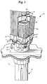
- Fig. 1 is a perspective view of a portion of the lower high pressure plenum, the fuel support casting, and four supported fuel rods on the fuel support casting, thus illustrating plenums down stream of the rod supporting grid in which the devices of this invention can be located;
- Fig. 2 is a side elevation schematic of the lower tie plate plenum illustrating a centrifugal flow debris trap including a static swirl inducing member adjacent the inlet orifice, an overlying strainer trap, and an underlying debris collector ring, ;
- Fig. 3 is a side elevation schematic of the lower tie plate plenum illustrating cone deflector in combination with a peripheral strainer ring, an overlying strainer trap, and an underlying debris collector ring; and,
- Fig. 4 is a stacked mesh filter debris trap in which successive overlying and underlying filter layers form a circuitous and trapping debris path and underlying debris collector.
- Referring to Fig. 1, a pertinent detail of a portion of a reactor core is shown. Control rod drive housing H has fuel support casting C supported thereon. Fuel support casting C includes
arm 16 which orients casting C with respect to pin 14 in core plate P. - Core plate P divides high pressure lower plenum L from core R, preserving the necessary pressure differential barrier to cause the controlled circulation within the many individual fuel bundles of the reactor.
- Fuel support casting C includes four
apertures 20 onto which four fuel bundles B at their respective lower tie plate assemblies T are placed. Each lower tie plate assembly T is disposed to cause its inlet nozzle N to communicate to one of theapertures 20 of the fuel support casting. - Fuel support casting C also includes apertures through which
control rods 22 penetrate to the interstices of the four fuel bundles sitting on top of the fuel support casting C. Since the action of the control rods is not important with respect to this invention, further discussion of this aspect of the reactor will not be included. - Each fuel bundle includes a plurality of
upstanding fuel rods 42 surrounded by achannel 44.Spacers 46 surround thefuel rods 42 discretely at several elevations and constitute locations where debris can be trapped, dynamically fretted by the passing coolant, and cause damage tofuel rods 42. Accordingly, and in this disclosure, the filter of this invention is located in any of the illustrated plenums to the rod supporting grid G of the lower tie plate (See Figs. 2, 3 and 4), or in the fuel support casting C. - In the following illustrations, the debris catchers of this invention will be illustrated with location in the lower tie plate flow plenum between the inlet orifice or nozzle N and the rod supporting grid G.
- Remembering further that only four out of a possible 750 fuel bundles are illustrated, it will be understood that the pressure drop across core plate P is important. Accordingly, a review of the pressure drop within a boiling water nuclear reactor can be instructive.
- First, and through an orifice (not shown) in the fuel support casting C, an approximate 7 to 8 psi pressure drop occurs at typical 100% power/100% flow operating conditions. This pressure drop is utilized to ensure uniform distribution of bundle coolant flow through the many (up to 750) fuel bundles within a boiling water nuclear reactor.
- Secondly, at in the lower tie plate of the fuel bundles on each fuel support casting C, approximately 1½ psi of pressure drop occurs. This pressure drop is a result primarily of the changes in flow velocity and direction occurring through this complex geometry structure.
- Finally, and as the coolant rises and generates steam within the fuel bundle, approximately 10 to 12 psi of pressure drop is incurred. This pressure drop is distributed throughout the length of the fuel bundle -- and is important to the operating stability of both the individual fuel bundles and the collective fuel bundles constituting the core of the nuclear reactor.
- The reader should understand that the summary of pressure drop given above is an over simplification. This is a very complex part of the design and operation of a nuclear reactor. Having said this much, one point must be stressed. Flow resistance within the individual fuel bundles of a boiling water must remain substantially unchanged. Accordingly, if apparatus for preventing debris entrainment into the fuel bundles is going to be utilized, appreciable change in overall fuel bundle flow resistance should be avoided.
- Regarding the overall performance of a debris catcher or trap, such structure must be capable of trapping particles small enough to be entrained but large enough to enter through the lower tie plate grid G and in between the
fuel rods 42. Such a structure must be structurally sound and especially avoid any failure resulting in loose parts. It is desired that the structure trap and retain debris particles. At the same time, adverse flow conditions into the fuel bundle should not be generated. - Finally, the filter should be such that it is not possible under any circumstances for the filter to become clogged and cause appreciable obstruction to the total flow into the fuel bundle B. Accordingly, and in the description of the specific embodiments that follow it will be seen that we utilize a filter structure that does not constitute a continuum of structure across the particular flow plenum being utilized. In each case -- assuming that the perforate portions of the filter become complete clogged -- it will be seen that unobstructed water coolant flow paths are preserved to the fuel rods.
- The following designs direct debris particles into screen or mesh paths that intercept only a fraction of the total flow path. This minimizes pressure drop. At the same time, solid portions can be incorporated to the mesh structures to impart required resistance to failure.
- Referring to Fig. 2, a side elevation section schematic of a lower tie plate assembly T is shown. This lower tie plate includes four
walls 52 defining a substantially square volume with tapered substantiallyconical wall 54 truncated at inlet nozzle N. Nozzle N includes abail 60 over the nozzle forming the lower most structure of the fuel bundle. - In the structure illustrated in Fig. 2, there is included a
debris collector ring 70.Ring 70 fastens interiorly of plenum P surrounding nozzle N and projects upwardly into the volume of plenum P. As will be realized hereafter,ring 70 forms between the inside ofconical wall 54 and the outside surface of ring 70 a trap for debris. - Secondly, located above or preferably within nozzle N is
static swirl vane 80.Swirl vane 80 imparts an upwardly spiralling flow to coolant flowing through nozzle N into plenum P. Such spiral flow classifies heavier debris to the outside ofring 70 with the lighter coolant flowing upwardly through rod supporting grid G. - Finally, mesh pick off
filter 90 includinghorizontal portion 92 and downward dependingring 94 is placed centrally of the structure. Preferably, the structure is perforate for allowing fluid flow through the mesh pick off structure; it will be understood that portions of this structure can be solid if desired. - Operation is easy to understand. Water coolant including debris enters nozzle N and has a swirling motion imparted by a
static swirl vane 60. Above the static swirl vane there is an open central flow path. Heavier debris --typically metal particles having 8 to 10 times the density of water -- are classified to the exterior of plenum P and trapped -- either byring 70 or overlying mesh pick offfilter 90. Debris is retained at these locations. At the same time, the open central flow path is not obstructed by a continuum of filter structure. Obstruction of the filter structure causing impeding of flow to thefuel rods 42 cannot occur. - It is anticipated that the length of pitch of
static swirl device 80 will be adjusted for optimum performance. Further, dimension ofdebris collector ring 70 and mesh pick offfilter 90 will likewise be adjusted for optimum trapping of debris. - It is to be noted that upon cessation of flow, debris trapped at mesh pick off
filter 90 will fall. In such a fall, trapping of the debris will occur atring 70. Thus, and in the case of the illustrated fuel bundle B, with removal of the fuel bundle removal of the debris will occur. - Referring to Fig. 3, a structure similar to Fig. 2 is illustrated with the exception of
cone deflector 100. This deflector peripherally diverts fluid to the plenum periphery at thecone 100. This cone can be constructed of mesh and/or solid material. -
Cone 100 extends beyondring 70 and terminates in dependingmesh ring 102. Dependingmesh ring 102 is outside ofring 70. - Operation is easy to understand. Debris entraining water coolant is deflected at
cone 100 with debris being trapped either atdebris collector ring 102 or the mesh pick off filter. Debris falling from either location -- either during coolant flow or after coolant flow has ceased -- will fall into the outside ofring 70 and be trapped byring 70 within lower tie plate T. - Referring to Fig. 4, a structure similar to that illustrated in Figs. 2 and 3 is illustrated in which
upper filter layer 124 and lower filter layer 114 impart the circuitous flow path to the passing fluid. - Lower filter structure 114 includes
cone filter 110 having a solid central ring 11 to define a central flow path. A peripherally slopingperforate cone 110 truncated at the central flow paths extends to perforatering 113. -
Upper filter layer 124 consists of peripheral annularperforate filter section 120 and central invertedconical basket 122.Conical basket 122 includes an invertedperforate cone section 126 and a dependingperforate ring section 127. - In operation, it will be seen that the disclosed design includes offset over-under placement of layered traps for debris particles. At the same time, open flow passages are preserved so that complete debris or corrosion clogging of the filter cannot occur. The sloped profile of the filter assists migration of the trapped debris to the collecting corners of the
upper filter layer 124. Debris falling from theseupper layer 124 corners is either trapped by lower filter layer 114 oroptional ring 70. - In the schematic of the apparatus herein illustrated, a ring, cone, and annulus structure is shown. The reader will understand that a straight structure across plenum P having the overall side elevation of the ring structure illustrated could as well be used.
Claims (10)
- In a boiling water reactor fuel bundle, a debris catching grid construction for placement within the flow volume defined by an inlet plenum to the lower tie plate assembly to the upper fuel rod supporting grid comprising:
means defining spatially separated structures across said plenum for imparting a flow direction (momentum) change to passing water coolant, said means defining said spatially separated structures not forming a continuum across said plenum;
means defining a trapping structure for the trapping separation of the debris separated from said water coolant by said flow direction change. - The invention of claim 1 and wherein:
said means defining spatially separated structures across said plenum includes spatially separated strainer structures. - The invention of claim 1 and wherein:
said means defining spatially separated structures across said plenum includes a static swirl vane. - The invention of claim 1 and wherein:
said means defining spatially separated structures across said plenum includes a deflecting cone. - The invention of claim 1 and wherein:
said means defining said spatially separated structures is located within a lower tie plate of a fuel bundle between an inlet orifice and said rod supporting grid. - In a boiling water reactor fuel bundle comprising in combination:
a plurality of upstanding side-by-side fuel rods;
a lower tie plate including a rod supporting grid for supporting said plurality of upstanding side-by-side fuel rods;
means for maintaining said fuel rods in upstanding side-by-side relation;
a channel surrounding said plurality of upstanding fuel rods from the vicinity of said lower rod supporting grid along the length of said fuel rods to form a discrete flow path through said fuel bundle;
an inlet plenum to the lower tie plate assembly to the upper fuel rod supporting grid;
means defining spatially separated structures across said inlet plenum for imparting flow direction change to passing water coolant, said means defining said spatially separated structure not forming a continuum across said plenum;
means defining a trapping structure for the trapping separation of the debris separated from said water coolant by said flow direction change. - The invention of claim 6 and wherein said means defining spatially separated structures across said plenum for imparting a circuitous flow path to passing water coolant, said means defining said spatially separated structure not forming a strainer continuum across said plenum includes:
a plurality of strainer structures, said structures placed in overlapping relationship across said plenum with spatial separation therebetween. - The invention of claim 7 and wherein said means defining trapping structures includes solid portions and perforate portions.
- The invention of claim 6 and wherein:
said inlet plenum includes a ring for trapping debris fastened to a portion of said plenum. - The invention of claim 9 and wherein:
said inlet plenum is located in said lower tie plate between an inlet orifice and said rod supporting grid.
Applications Claiming Priority (2)
| Application Number | Priority Date | Filing Date | Title |
|---|---|---|---|
| US110744 | 1993-08-23 | ||
| US08/110,744 US5390221A (en) | 1993-08-23 | 1993-08-23 | Debris filters with flow bypass for boiling water reactors |
Publications (1)
| Publication Number | Publication Date |
|---|---|
| EP0640987A1 true EP0640987A1 (en) | 1995-03-01 |
Family
ID=22334697
Family Applications (1)
| Application Number | Title | Priority Date | Filing Date |
|---|---|---|---|
| EP94305688A Withdrawn EP0640987A1 (en) | 1993-08-23 | 1994-08-01 | Debris filters with flow bypass for boiling water reactors |
Country Status (4)
| Country | Link |
|---|---|
| US (1) | US5390221A (en) |
| EP (1) | EP0640987A1 (en) |
| JP (1) | JPH07151882A (en) |
| TW (1) | TW255833B (en) |
Families Citing this family (29)
| Publication number | Priority date | Publication date | Assignee | Title |
|---|---|---|---|---|
| US5490189A (en) * | 1994-09-22 | 1996-02-06 | B&W Fuel Company | Nuclear fuel assembly debris filter |
| US5539793A (en) * | 1994-10-27 | 1996-07-23 | General Electric Company | Lower tie plate debris catcher for a nuclear reactor |
| US5528640A (en) * | 1994-11-07 | 1996-06-18 | General Electric Company | Low pressure double offset plate catcher for a nuclear reactor |
| US5748694A (en) * | 1996-03-26 | 1998-05-05 | General Electric Company | Fuel bundle filter for a nuclear reactor fuel bundle assembly |
| JPH11133176A (en) * | 1997-08-29 | 1999-05-21 | Toshiba Corp | Fuel assembly |
| JP4006678B2 (en) | 2001-12-25 | 2007-11-14 | 株式会社グローバル・ニュークリア・フュエル・ジャパン | Nuclear fuel assembly lower tie plate and assembly method thereof |
| US20060018422A1 (en) * | 2004-07-20 | 2006-01-26 | Mayer John A | Nuclear fuel assembly end cap arrangement |
| US20070084782A1 (en) * | 2005-10-05 | 2007-04-19 | Enercon Services, Inc. | Filter medium for strainers used in nuclear reactor emergency core cooling systems |
| US8054932B2 (en) * | 2005-10-05 | 2011-11-08 | Enercon Services, Inc. | Filter medium for strainers used in nuclear reactor emergency core cooling systems |
| DE102006038748B3 (en) * | 2006-07-22 | 2008-02-28 | Areva Np Gmbh | Device for removing solid particles from the circulating in the primary circuit of a nuclear reactor cooling medium |
| US9620249B2 (en) * | 2007-08-31 | 2017-04-11 | Global Nuclear Fuel—Americas, LLC | Debris shield upper tie plate for nuclear fuel assembly and method to shield assembly from debris |
| US20090060114A1 (en) * | 2007-08-31 | 2009-03-05 | Global Nuclear Fuel - Americas, Llc | Debris shield for upper tie plate in a nuclear fuel bundle and method for filtering debris |
| KR101515116B1 (en) | 2007-12-26 | 2015-04-24 | 토륨 파워 인코포레이티드 | Nuclear reactor(variants), fuel assembly consisting of driver-breeding modules for a nuclear reactor(variants) and a fuel cell for a fuel assembly |
| US8116423B2 (en) | 2007-12-26 | 2012-02-14 | Thorium Power, Inc. | Nuclear reactor (alternatives), fuel assembly of seed-blanket subassemblies for nuclear reactor (alternatives), and fuel element for fuel assembly |
| US8208597B2 (en) * | 2008-07-31 | 2012-06-26 | Global Nuclear Fuel - Americas, Llc | Channel confinement system and method for dry-storage of BWR fuel bundles |
| HUE043364T2 (en) | 2008-12-25 | 2019-08-28 | Thorium Power Inc | A fuel element and a method of manufacturing a fuel element for a fuel assembly of a nuclear reactor |
| US8548113B2 (en) * | 2009-08-28 | 2013-10-01 | Global Nuclear Fuel - Americas, Llc | Debris mitigation upper tie plates and fuel bundles using the same |
| WO2011143172A1 (en) | 2010-05-11 | 2011-11-17 | Thorium Power, Inc. | Fuel assembly with metal fuel alloy kernel and method of manufacturing thereof |
| US10170207B2 (en) | 2013-05-10 | 2019-01-01 | Thorium Power, Inc. | Fuel assembly |
| US10192644B2 (en) | 2010-05-11 | 2019-01-29 | Lightbridge Corporation | Fuel assembly |
| KR101000897B1 (en) * | 2010-06-07 | 2010-12-13 | 비에이치아이 주식회사 | Strainer wall structure and filtering method using the strainer wall structure and manufacturing method for the strainer wall structure |
| KR101016549B1 (en) * | 2010-08-12 | 2011-02-24 | 비에이치아이 주식회사 | Strainer wall structure including curved sections and manufacturing method for the strainer wall structure and filtering method using the strainer wall structure |
| US8611488B2 (en) * | 2011-02-14 | 2013-12-17 | Global Nuclear Fuel—Americas, LLC | Debris exclusion and retention device for a fuel assembly |
| US8797021B2 (en) | 2011-02-14 | 2014-08-05 | Ge-Hitachi Nuclear Energy Americas Llc | Electrochemical corrosion potential probe assembly |
| US8393437B2 (en) | 2011-02-15 | 2013-03-12 | Westinghouse Electric Company Llc | Noise and vibration mitigation system for nuclear reactors employing an acoustic side branch resonator |
| CN104081466B (en) | 2011-12-12 | 2017-12-15 | 控制工程学公司 | Particulate removal systems |
| US9561454B2 (en) * | 2012-10-09 | 2017-02-07 | Ovivo Inc. | Debris filter with splitter bar |
| US9715947B2 (en) * | 2013-08-09 | 2017-07-25 | Ge-Hitachi Nuclear Energy Americas Llc | Systems for debris mitigation in nuclear reactor safety systems |
| CN113851243B (en) * | 2021-10-19 | 2024-01-30 | 上海核工程研究设计院股份有限公司 | Cofferdam device with debris collection function in nuclear power station |
Citations (8)
| Publication number | Priority date | Publication date | Assignee | Title |
|---|---|---|---|---|
| JPS5419080A (en) * | 1977-07-13 | 1979-02-13 | Toshiba Corp | Nuclear fuel supporting metal fitting |
| SU686742A1 (en) * | 1977-06-08 | 1979-09-25 | Предприятие П/Я Г-4371 | Hydraulic filter |
| JPS6296891A (en) * | 1985-10-24 | 1987-05-06 | 株式会社東芝 | Fuel aggregate |
| US4678627A (en) * | 1985-04-04 | 1987-07-07 | Westinghouse Electric Corp. | Debris-retaining trap for a fuel assembly |
| GB2206508A (en) * | 1987-07-09 | 1989-01-11 | Teleco Oilfield Services Inc | Centrifugal debris catcher |
| JPH03111795A (en) * | 1989-09-27 | 1991-05-13 | Nuclear Fuel Ind Ltd | Nuclear fuel assembly |
| EP0432738A1 (en) * | 1989-12-14 | 1991-06-19 | Abb Atom Ab | Fuel assembly for a boiling water nuclear reactor |
| GB2271728A (en) * | 1992-10-15 | 1994-04-27 | Edward John Roberts | Suction cleaner |
Family Cites Families (70)
| Publication number | Priority date | Publication date | Assignee | Title |
|---|---|---|---|---|
| US1240081A (en) * | 1917-02-15 | 1917-09-11 | Francis Evan Moss | Apparatus for separating solid matters from fluids or fluids from fluids. |
| US1504233A (en) * | 1921-11-07 | 1924-08-12 | Graham Lou Ellen | Drain protector |
| US1992472A (en) * | 1933-09-16 | 1935-02-26 | Roby E Proector | Sediment separating trap |
| DE1514462A1 (en) * | 1965-05-19 | 1969-08-28 | Siemens Ag | Fuel element for nuclear reactors |
| GB1169714A (en) * | 1966-08-08 | 1969-11-05 | Atomic Energy Authority Uk | Nuclear Reactor Fuel Elements |
| US3725199A (en) * | 1969-04-09 | 1973-04-03 | Combustion Eng | Nuclear reactor organization and fuel assembly arrangement |
| US3844888A (en) * | 1971-01-04 | 1974-10-29 | Combustion Eng | Helical flow deflector cone for fuel element assemblies |
| US3840051A (en) * | 1971-03-11 | 1974-10-08 | Mitsubishi Heavy Ind Ltd | Straightener |
| US3801453A (en) * | 1972-02-11 | 1974-04-02 | Transfer Systems | Fuel assembly for power generating nuclear reactor |
| SE363184B (en) * | 1972-05-17 | 1974-01-07 | Asea Atom Ab | |
| GB1422796A (en) * | 1972-08-07 | 1976-01-28 | Atomic Energy Authority Uk | Improvements in nuclear reactors |
| GB1461275A (en) * | 1973-08-24 | 1977-01-13 | Atomic Energy Authority Uk | Liquid cooled nuclear reactors |
| US3878870A (en) * | 1974-04-16 | 1975-04-22 | Atomic Energy Commission | Orifice design for the control of coupled region flow |
| CA1032668A (en) * | 1974-05-20 | 1978-06-06 | John M. Shallenberger | Modular in-core flow filter for a nuclear reactor |
| US4053359A (en) * | 1974-09-04 | 1977-10-11 | The United States Of America As Represented By The United States Energy Research And Development Administration | Nuclear reactor |
| US4053358A (en) * | 1974-12-30 | 1977-10-11 | The United States Of America As Represented By The United States Energy Research And Development Administration | Modular assembly for supporting, straining, and directing flow to a core in a nuclear reactor |
| GB1510127A (en) * | 1974-12-31 | 1978-05-10 | Atomic Energy Authority Uk | Nuclear reactor fuel element assemblies |
| GB1518292A (en) * | 1975-05-07 | 1978-07-19 | Atomic Energy Authority Uk | Nuclear reactor fuel sub-assemblies |
| FR2326764A1 (en) * | 1975-10-02 | 1977-04-29 | Commissariat Energie Atomique | CORE STRUCTURE FOR NUCLEAR REACTOR |
| US4116764A (en) * | 1976-02-11 | 1978-09-26 | The United States Of America As Represented By The United States Department Of Energy | Apparatus for controlling nuclear core debris |
| GB1582192A (en) * | 1977-06-03 | 1980-12-31 | Nuclear Power Co Ltd | Fuel sub-assemblies for nuclear reactors |
| FR2488033A1 (en) * | 1980-07-31 | 1982-02-05 | Framatome Sa | DEVICE FOR PROTECTING CONTROLLING CLUSTER CONTROL MECHANISMS DURING TESTING OF A NUCLEAR REACTOR |
| FR2491668B1 (en) * | 1980-10-08 | 1985-10-11 | Framatome Sa | NUCLEAR REACTOR FUEL ASSEMBLY |
| SE424237B (en) * | 1980-10-29 | 1982-07-05 | Asea Atom Ab | FUEL ELEMENT FOR A COOKING REACTOR |
| JPS57102215A (en) * | 1980-12-17 | 1982-06-25 | Ishikawajima Harima Heavy Ind Co Ltd | Strainer |
| FR2500653A1 (en) * | 1981-02-26 | 1982-08-27 | Commissariat Energie Atomique | DEVICE FOR ADJUSTING THE FLOW OF A FLUID |
| US4427624A (en) * | 1981-03-02 | 1984-01-24 | Westinghouse Electric Corp. | Composite nozzle design for reactor fuel assembly |
| US4412969A (en) * | 1982-03-09 | 1983-11-01 | Tilbrook Roger W | Combination pipe rupture mitigator and in-vessel core catcher |
| US4615862A (en) * | 1983-12-21 | 1986-10-07 | Westinghouse Electric Corp. | Nuclear reactor with fuel assembly support means |
| US4614636A (en) * | 1984-01-09 | 1986-09-30 | Westinghouse Electric Corp. | 17×17 Nuclear fuel assembly thimble tube cap |
| US4655995A (en) * | 1984-05-11 | 1987-04-07 | Westinghouse Electric Corp. | Reversible BWR fuel assembly and method of using same |
| US4610838A (en) * | 1984-07-26 | 1986-09-09 | Westinghouse Electric Corp. | Method for removing debris from a nuclear reactor vessel |
| US4634525A (en) * | 1984-10-04 | 1987-01-06 | Westinghouse Electric Corp. | Loose parts filter |
| US4684495A (en) * | 1984-11-16 | 1987-08-04 | Westinghouse Electric Corp. | Fuel assembly bottom nozzle with integral debris trap |
| US4684496A (en) * | 1984-11-16 | 1987-08-04 | Westinghouse Electric Corp. | Debris trap for a pressurized water nuclear reactor |
| US4664880A (en) * | 1984-12-07 | 1987-05-12 | Westinghouse Electric Corp. | Wire mesh debris trap for a fuel assembly |
| FR2577343B1 (en) * | 1985-02-08 | 1991-03-22 | Commissariat Energie Atomique | DEVICE FOR SPACING AND HOLDING COMBUSTIBLE PENCILS IN A FUEL ASSEMBLY |
| US4652425A (en) * | 1985-08-08 | 1987-03-24 | Westinghouse Electric Corp. | Bottom grid mounted debris trap for a fuel assembly |
| US4716012A (en) * | 1985-10-07 | 1987-12-29 | Westinghouse Electric Corp. | Reactor internals loose parts strainer |
| JPS6361183A (en) * | 1986-09-01 | 1988-03-17 | 三菱原子燃料株式会社 | Fuel rod |
| JPS63157093A (en) * | 1986-12-22 | 1988-06-30 | 三菱原子燃料株式会社 | Nuclear fuel aggregate |
| US4849161A (en) * | 1987-02-19 | 1989-07-18 | Advanced Nuclear Fuels Corp. | Debris-resistant fuel assembly |
| US4781884A (en) * | 1987-03-02 | 1988-11-01 | Combustion Engineering, Inc. | Debris catching strainer grid |
| EP0289829B1 (en) * | 1987-05-05 | 1993-06-23 | Westinghouse Electric Corporation | Nuclear fuel assembly with a debris-filter bottom nozzle |
| US4900507A (en) * | 1987-05-05 | 1990-02-13 | Westinghouse Electric Corp. | Nuclear fuel assembly debris filter bottom nozzle |
| JPS6439593A (en) * | 1987-08-05 | 1989-02-09 | Nippon Atomic Ind Group Co | Peripheral part fuel supporting metallic fitting |
| JPS6483189A (en) * | 1987-09-25 | 1989-03-28 | Mitsubishi Nuclear Fuel | Fuel assembly |
| US4828791A (en) * | 1987-10-05 | 1989-05-09 | Westinghouse Electric Corp. | Nuclear fuel assembly debris resistant bottom nozzle |
| US4832905A (en) * | 1988-04-15 | 1989-05-23 | Combustion Engineering, Inc. | Lower end fitting debris collector |
| US5024807A (en) * | 1988-12-05 | 1991-06-18 | Combustion Engineering, Inc. | Debris catching spring detent spacer grid |
| US4919883A (en) * | 1988-12-14 | 1990-04-24 | Combustion Engineering, Inc. | Lower end fitting debris collector and end cap spacer grid |
| DE69001678T2 (en) * | 1989-01-13 | 1993-09-02 | Hitachi Ltd | FUEL ARRANGEMENTS. |
| FR2646005B1 (en) * | 1989-04-12 | 1991-07-26 | Framatome Sa | LOWER NOZZLE OF A FUEL ASSEMBLY OF A NUCLEAR REACTOR COMPRISING A PARTICLE RETAINING FILTER |
| FR2646006B1 (en) * | 1989-04-12 | 1993-12-03 | Framatome | LOWER NOZZLE OF A FUEL ASSEMBLY COMPRISING A PARTICLE RETAINING DEVICE |
| FR2646004B1 (en) * | 1989-04-12 | 1993-12-24 | Framatome | FILTRATION PLATE ASSOCIATED WITH A LOWER NOZZLE OF A FUEL ASSEMBLY OF A NUCLEAR REACTOR |
| FR2647944B1 (en) * | 1989-06-02 | 1993-12-10 | Framatome | FUEL ASSEMBLY OF A NUCLEAR REACTOR COMPRISING A DEVICE FOR RETAINING PARTICLES CONTAINED IN THE REACTOR COOLING FLUID |
| US4980121A (en) * | 1989-07-28 | 1990-12-25 | Westinghouse Electric Corp. | Protective device for lower end portion of a nuclear fuel rod cladding |
| US5024806A (en) * | 1989-09-21 | 1991-06-18 | Westinghouse Electric Corp. | Enhanced debris filter bottom nozzle for a nuclear fuel assembly |
| US5094802A (en) * | 1989-10-13 | 1992-03-10 | B&W Fuel Company | Nuclear fuel assembly debris filter |
| US5037605A (en) * | 1989-10-13 | 1991-08-06 | B&W Fuel Company | Nuclear fuel assembly debris filter |
| US5071617A (en) * | 1989-12-11 | 1991-12-10 | Combustion Engineering, Inc. | Reduced flow resistance cast lower end fitting |
| US5219517A (en) * | 1989-12-14 | 1993-06-15 | Abb Atom Ab | Fuel assembly for a boiling water nuclear reactor |
| SE465192B (en) * | 1989-12-15 | 1991-08-05 | Asea Atom Ab | BRAENSLEPATRON CARRIES A NUCLEAR WATER TYPE REACTOR |
| FR2656456B1 (en) * | 1989-12-21 | 1992-04-24 | Framatome Sa | LOWER TIP OF A FUEL ASSEMBLY OF A NUCLEAR REACTOR COOLED BY LIGHT WATER. |
| US5030412A (en) * | 1990-05-04 | 1991-07-09 | Advanced Nuclear Fuels Corporation | Fuel assembly debris screen |
| ES2077102T3 (en) * | 1990-05-04 | 1995-11-16 | Siemens Ag | ASSEMBLY OF LOWER ANCHOR PLATE RESISTANT TO DRIVE ACTION. |
| FR2664733B1 (en) * | 1990-07-11 | 1992-11-06 | Framatome Sa | LOWER NOZZLE OF A FUEL ASSEMBLY FOR NUCLEAR REACTOR COMPRISING AN ADAPTER PLATE AND A FILTRATION PLATE ATTACHED TO THE ADAPTER PLATE. |
| US5009839A (en) * | 1990-09-04 | 1991-04-23 | B&W Fuel Company | Nuclear fuel assembly bottom nozzle plate |
| SE469046B (en) * | 1991-02-11 | 1993-05-03 | Asea Atom Ab | BRAENSLEPATRON CARRIES A NUCLEAR WATER TYPE REACTOR |
| US5282231A (en) * | 1992-09-23 | 1994-01-25 | Siemens Power Corporation | Lower tie plate cast frame |
-
1993
- 1993-08-23 US US08/110,744 patent/US5390221A/en not_active Expired - Fee Related
-
1994
- 1994-04-09 TW TW083103118A patent/TW255833B/zh active
- 1994-08-01 EP EP94305688A patent/EP0640987A1/en not_active Withdrawn
- 1994-08-22 JP JP6195842A patent/JPH07151882A/en not_active Withdrawn
Patent Citations (8)
| Publication number | Priority date | Publication date | Assignee | Title |
|---|---|---|---|---|
| SU686742A1 (en) * | 1977-06-08 | 1979-09-25 | Предприятие П/Я Г-4371 | Hydraulic filter |
| JPS5419080A (en) * | 1977-07-13 | 1979-02-13 | Toshiba Corp | Nuclear fuel supporting metal fitting |
| US4678627A (en) * | 1985-04-04 | 1987-07-07 | Westinghouse Electric Corp. | Debris-retaining trap for a fuel assembly |
| JPS6296891A (en) * | 1985-10-24 | 1987-05-06 | 株式会社東芝 | Fuel aggregate |
| GB2206508A (en) * | 1987-07-09 | 1989-01-11 | Teleco Oilfield Services Inc | Centrifugal debris catcher |
| JPH03111795A (en) * | 1989-09-27 | 1991-05-13 | Nuclear Fuel Ind Ltd | Nuclear fuel assembly |
| EP0432738A1 (en) * | 1989-12-14 | 1991-06-19 | Abb Atom Ab | Fuel assembly for a boiling water nuclear reactor |
| GB2271728A (en) * | 1992-10-15 | 1994-04-27 | Edward John Roberts | Suction cleaner |
Non-Patent Citations (4)
| Title |
|---|
| DATABASE WPI Week 8020, Derwent World Patents Index; AN 80-36037C * |
| DATABASE WPI Week 8724, Derwent World Patents Index; AN 87-165900 * |
| PATENT ABSTRACTS OF JAPAN vol. 15, no. 312 (P - 1236) 9 August 1991 (1991-08-09) * |
| PATENT ABSTRACTS OF JAPAN vol. 3, no. 42 (M - 55) 12 April 1979 (1979-04-12) * |
Also Published As
| Publication number | Publication date |
|---|---|
| JPH07151882A (en) | 1995-06-16 |
| TW255833B (en) | 1995-09-01 |
| US5390221A (en) | 1995-02-14 |
Similar Documents
| Publication | Publication Date | Title |
|---|---|---|
| US5390221A (en) | Debris filters with flow bypass for boiling water reactors | |
| US5483564A (en) | Lower tie plate strainers including double corrugated strainers for boiling water reactors | |
| US5345483A (en) | Lower tie plate strainers having double plate with offset holes for boiling water reactors | |
| US5384814A (en) | Lower tie plate strainers for boiling water reactors | |
| US5528640A (en) | Low pressure double offset plate catcher for a nuclear reactor | |
| US5390220A (en) | Lower tie plate strainers including helical spring strainers for boiling water reactors | |
| EP0422950B1 (en) | Nuclear fuel assembly with debris filter | |
| US5748694A (en) | Fuel bundle filter for a nuclear reactor fuel bundle assembly | |
| EP0184219A1 (en) | Debris trap for a nuclear fuel assembly | |
| JP2690706B2 (en) | Integrated lower tie plate lattice in nuclear fuel assemblies | |
| US5416812A (en) | Optimized critical power in a fuel bundle with part length rods | |
| EP2487690B1 (en) | Debris exclusion and retention device for a fuel assembly | |
| US5539793A (en) | Lower tie plate debris catcher for a nuclear reactor | |
| EP2642488B1 (en) | Bottom nozzle filter device and debris-resistant bottom nozzle using the device | |
| US5327470A (en) | Spacer with steam separator | |
| EP0432738B1 (en) | Fuel assembly for a boiling water nuclear reactor | |
| EP0690453B1 (en) | Boiling water reactor fuel assembly filter | |
| US5519745A (en) | Lower tie plate debris catcher for a nuclear reactor | |
| US5481578A (en) | Perforated tube debris catcher for a nuclear reactor | |
| JPH0843570A (en) | Lower tie-plate lattice as unitary body in nuclear fuel assembly | |
| US5668728A (en) | Removable deflectors for bwr fuel with steam vents and part-length rods | |
| US5471514A (en) | Fuel element for a light-water nuclear reactor | |
| EP0709856A1 (en) | Nuclear reactor fuel assembly comprising a plate type debris catcher | |
| KR20190126931A (en) | Mixed water spurs nozzles and how to use them in reactors | |
| EP0992039A1 (en) | Nuclear fuel assembly |
Legal Events
| Date | Code | Title | Description |
|---|---|---|---|
| PUAI | Public reference made under article 153(3) epc to a published international application that has entered the european phase |
Free format text: ORIGINAL CODE: 0009012 |
|
| AK | Designated contracting states |
Kind code of ref document: A1 Designated state(s): CH DE ES LI SE |
|
| 17P | Request for examination filed |
Effective date: 19950901 |
|
| 17Q | First examination report despatched |
Effective date: 19960308 |
|
| STAA | Information on the status of an ep patent application or granted ep patent |
Free format text: STATUS: THE APPLICATION IS DEEMED TO BE WITHDRAWN |
|
| 18D | Application deemed to be withdrawn |
Effective date: 19960919 |