EP0640418B2 - Production of cast steel parts provided with inner cavities - Google Patents
Production of cast steel parts provided with inner cavities Download PDFInfo
- Publication number
- EP0640418B2 EP0640418B2 EP93500118A EP93500118A EP0640418B2 EP 0640418 B2 EP0640418 B2 EP 0640418B2 EP 93500118 A EP93500118 A EP 93500118A EP 93500118 A EP93500118 A EP 93500118A EP 0640418 B2 EP0640418 B2 EP 0640418B2
- Authority
- EP
- European Patent Office
- Prior art keywords
- parts
- casting
- production
- projection
- core
- Prior art date
- Legal status (The legal status is an assumption and is not a legal conclusion. Google has not performed a legal analysis and makes no representation as to the accuracy of the status listed.)
- Expired - Lifetime
Links
Images


Classifications
-
- B—PERFORMING OPERATIONS; TRANSPORTING
- B22—CASTING; POWDER METALLURGY
- B22C—FOUNDRY MOULDING
- B22C9/00—Moulds or cores; Moulding processes
- B22C9/10—Cores; Manufacture or installation of cores
-
- B—PERFORMING OPERATIONS; TRANSPORTING
- B22—CASTING; POWDER METALLURGY
- B22C—FOUNDRY MOULDING
- B22C9/00—Moulds or cores; Moulding processes
- B22C9/20—Stack moulds, i.e. arrangement of multiple moulds or flasks
Definitions
- the present invention relates to improvements introduced in the production of cast steel parts provided with inner cavities, particularly concerning a mould assembly therefor, which permit substantial advantages to be obtained relative to the present state of the art.
- the steel parts to be produced according to the present invention are preferably wear-resistant cast steel parts, in particular the teeth of excavators and other earth-moving machines, in which the part has a generally pointed structure with an inner cavity, which is open at one end of the part, thus permitting it to be connected to an acceptance or male part of the machine, and therefore enabling it to be replaced when it is worn.
- the improvements which constitute the basis of the present invention are based substantially on the production of parts by means of a filling system using moulds comprising successive stacking of compartments or casting boxes, each of which has a set of parts supplied from a collector or central casting block, which facilitates successive filling of each of the levels of the mould formed by the various compartments, in association with specific means of designing the inner cavity of the part, in order to obtain controlled localisation of its recess, thus making it compatible with correct resistance of the part.
- improved quality of the part is obtained by using moulds which are more highly resistant, thus enabling defects caused by inclusions of sand to be avoided, and providing improvements in the surface appearance of the product, as well as providing improved dimensional accuracy thereof.
- An additional advantage consists of reducing the burr on the parts, thus reducing the finishing time necessary.
- Another feature of the present improvements consists of the reduced consumption of sand for a specific quantity of steel cast, thus constituting an additional cost-reduction factor.
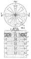
- the present invention is based on the preparation of multiple boxes such as 1, 2, 3, 4, 5 and 6, with their corresponding cores, forming a mould assembly in which there are distributed multiple levels of individual parts as indicated by number 7 in Figure 1, of a variable number and arrangement, which in the example shown is radial, but which could be of another type, originating in a common axial filling duct 8, without any sinkheads whatsoever.
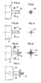
- each of the individual components produced such as a tooth for an earth-moving machine, designated 15 in Figure 5, consists of a cast steel part provided with an inner cavity 16, which is open at the end connection surface 17 of the tooth, and which, according to the present invention, has a projection 18, which is constituted in a specific manner at the time of casting, in order to obtain localisation of the recess in an inner area of the tooth, preferably in an area which corresponds to the neutral line of the part, and in conditions of separation relative to the outer surface of the part, in order to avoid fragile areas.
- the present invention also includes the optional arrangement of thickened parts such as 19, which are designed to provide a larger cross-section of the material in the area in which the inner recess will be provided.
- the cross-section of the projection 20 will be variable according to the needs of each case, for example it can be circular, as shown in Figures 8 and 9, or it can be a truncated pyramid, as in the projection 22 in Figures 10 and 11, or it can be lobar, as in the projection 23 in Figures 12 and 13, which has a head 24 consisting of a series of projecting lobes, which may be pointed.
- the projection can also be of the detachable type, as shown in Figure 14, in which the male part 25 has an aperture in which there is mounted the projection 26, which, in the case shown, is a lobar head 27.
- the area of the projection, indicated 28 is disposed in a preferably neutral area of the part 29, such that the recess which is formed in this area 28 does not have any functional consequences on the finished part.
- the communication with the atmosphere via the sand 30 of the core enables the pressures to be equalised in the recess area, thus avoiding local depressions, such as those which would occur in an inner recess without the control provided according to the present invention.
- the nature of the projection 28 is such that it facilitates communication with the atmosphere, as previously described, without also facilitating the addition of heat and gases, by which means the recess formed is controlled.
Description
- The present invention relates to improvements introduced in the production of cast steel parts provided with inner cavities, particularly concerning a mould assembly therefor, which permit substantial advantages to be obtained relative to the present state of the art.
- The steel parts to be produced according to the present invention are preferably wear-resistant cast steel parts, in particular the teeth of excavators and other earth-moving machines, in which the part has a generally pointed structure with an inner cavity, which is open at one end of the part, thus permitting it to be connected to an acceptance or male part of the machine, and therefore enabling it to be replaced when it is worn.
- US Patent 2.101.046 to Blettner discloses some improvements in the casting of a plurality of pistons for combustion engines, however, no reference is made to the problems of internal recesses in steel castings, or to measures for controlling the location of said recesses.
- Owing to the complex structure of the part, conventional casting methods require the use of sinkheads with sufficient additional volume to permit localisation of the recess which is formed at the end of the period of solidification of the part, thus enabling sound parts to be obtained. In the methods currently known, the dimensions of the assembly of each casting box, with its core or compartment, and the corresponding sinkheads, thus need to be considerable in order for these parts to be produced.
- Owing to the need to reduce the price of the parts, at the same time as obtaining a high quality thereof, it has become necessary in the industry to improve the production method of these parts, by obtaining optimum use of the steel employed in the casting, thus providing a high coefficient of use of the said cast steel mass, and simultaneously permitting a larger number of parts to be cast for a specific volume of boxes stacked, in order to obtain increased productivity.
- These have been the objectives of the applicants in developing their invention, which can be summarised as:
- improvement of the system of filling and supply of the parts, thus obtaining improved output measured in terms of the ratio between cast steel and net steel;
- reduction of the need for molten steel, since, as the quantity of fluid steel for a specific production is reduced, the capacity of the casting means can be smaller, and optionally some of the furnaces currently used in the casting installations can be eliminated;
- increase of the quantity of parts per mould;
- improvement of the final quality of the parts;
- reduction of the production costs.
- In order to achieve these objectives, the improvements which constitute the basis of the present invention are based substantially on the production of parts by means of a filling system using moulds comprising successive stacking of compartments or casting boxes, each of which has a set of parts supplied from a collector or central casting block, which facilitates successive filling of each of the levels of the mould formed by the various compartments, in association with specific means of designing the inner cavity of the part, in order to obtain controlled localisation of its recess, thus making it compatible with correct resistance of the part.
- Substantially these improvements are characterised in that at the end of the core which corresponds to the inner cavity of each of the parts, there is provided a projection for controlling a recess which is disposed inside the part, in the area distant from the outer surface thereof, the entire filling taking place from the single central filling duct, without supply sinkheads.
- It is thus possible to obtain the above-described objectives, by eliminating the sinkhead systems conventionally required, and permitting casting of a large number of parts simultaneously, without requiring sinkheads.
- At the same time, a considerable increase of weight of the metal is obtained by opening the casting ladle, enabling furnace sizes larger than those currently used habitually to be worked, and thus obtaining steel at a lower processing cost.
- Additionally, improved quality of the part is obtained by using moulds which are more highly resistant, thus enabling defects caused by inclusions of sand to be avoided, and providing improvements in the surface appearance of the product, as well as providing improved dimensional accuracy thereof.
- Similarly, the formation of cold areas in the parts is avoided, owing mainly to the reduced path of the steel, and to the increased metallostatic pressure and the low level of cooling produced by the new type of mould.
- An additional advantage consists of reducing the burr on the parts, thus reducing the finishing time necessary.
- Another feature of the present improvements consists of the reduced consumption of sand for a specific quantity of steel cast, thus constituting an additional cost-reduction factor.
- For the purpose of improved understanding, explanatory drawings of a preferred embodiment of the improvements which form the basis of the present invention are attached by way of example.
- Figure 1 is a schematic plan view showing the arrangement of a mould assembly for the production of steel parts in accordance with the present invention.
- Figure 2 is a longitudinal cross-section through the cutting plane indicated in Figure 1;
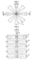
- Figure 3 shows schematically a plan view of the assembly produced by casting in accordance with the present invention, corresponding to one of the compartments;
- Figure 4 is an elevated view of the assembly of casting components along a cross-section through the cutting area indicated in Figure 3;
- Figure 5 is a longitudinal cross-section of a part produced in accordance with the present invention;
- Figure 6 is a plan view of the part shown in Figure 5;
- Figure 7 is a cross-section through the plane indicated in Figure 6;
- Figure 8 shows in detail the end of a male part or core corresponding to the inner cavity of the cast part;
- Figure 9 is a transverse cross-section through the plane indicated in Figure 8;
- Figure 10 and 11 are views corresponding to Figures 8 and 9, in a truncated pyramid end projection version;
- Figures 12 and 13 are a lateral view and a cross-section through a cutting plane indicated of an end projection similar to Figures 8 and 9, with a lobar end;
- Figure 14 shows a detachable-type end projection;
- Figure 15 is an enlarged cross-section corresponding to the casting of a part according to the present invention.
-
- As will be appreciated from the Figures, the present invention is based on the preparation of multiple boxes such as 1, 2, 3, 4, 5 and 6, with their corresponding cores, forming a mould assembly in which there are distributed multiple levels of individual parts as indicated by
number 7 in Figure 1, of a variable number and arrangement, which in the example shown is radial, but which could be of another type, originating in a commonaxial filling duct 8, without any sinkheads whatsoever. - After removal from the mould has taken place, the component shown in Figures 3 and 4 is obtained, in which multiple levels, i.e. 9, 10, 11, 12 and 13 can be seen, each of which consists of a number of individual parts which in this case are disposed radially without a sinkhead, as can be seen from Figures 1 and 3, starting from the same
central block 14, which has previously been used for filling. - According to the present invention, each of the individual components produced, such as a tooth for an earth-moving machine, designated 15 in Figure 5, consists of a cast steel part provided with an
inner cavity 16, which is open at theend connection surface 17 of the tooth, and which, according to the present invention, has aprojection 18, which is constituted in a specific manner at the time of casting, in order to obtain localisation of the recess in an inner area of the tooth, preferably in an area which corresponds to the neutral line of the part, and in conditions of separation relative to the outer surface of the part, in order to avoid fragile areas. The present invention also includes the optional arrangement of thickened parts such as 19, which are designed to provide a larger cross-section of the material in the area in which the inner recess will be provided. - In order to obtain accurate localisation of the inner recess in the
cavity 18, according to the present invention, in the end of the male part designed for producing thecavity 17, as shown in the examples in Figures 8 to 13, there is aprojection 20 in the end of themale part 21, Figures 8 and 9, such that thesaid projection 20 can ensure communication of the recess produced with the atmosphere, by means of its own core, by producing gas and heat, such that control of the recess formed is obtained, and that by providing the connection with the atmosphere, problems of deformation of the part are avoided, since normally, in the area in which the inner recess is formed, a depression caused by the pressure difference may occur. - The cross-section of the
projection 20 will be variable according to the needs of each case, for example it can be circular, as shown in Figures 8 and 9, or it can be a truncated pyramid, as in theprojection 22 in Figures 10 and 11, or it can be lobar, as in theprojection 23 in Figures 12 and 13, which has ahead 24 consisting of a series of projecting lobes, which may be pointed. - According to the present invention, the projection can also be of the detachable type, as shown in Figure 14, in which the
male part 25 has an aperture in which there is mounted theprojection 26, which, in the case shown, is alobar head 27. - By means of this arrangement of components as shown in Figure 15, during casting the area of the projection, indicated 28, is disposed in a preferably neutral area of the
part 29, such that the recess which is formed in thisarea 28 does not have any functional consequences on the finished part. The communication with the atmosphere via thesand 30 of the core enables the pressures to be equalised in the recess area, thus avoiding local depressions, such as those which would occur in an inner recess without the control provided according to the present invention. - The nature of the
projection 28 is such that it facilitates communication with the atmosphere, as previously described, without also facilitating the addition of heat and gases, by which means the recess formed is controlled. - As will be appreciated, the present invention has been explained relative to embodiments of which the details can be varied according to the capabilities of persons skilled in the art, without departing from the context of the claims.
Claims (2)
- Mould assembly for the production of cast steel parts, provided with inner cavities, in which the moulds are radially arranged in a stack about a common filling conduit, each mould comprising a core for the production of parts with a hollow end, the core communicating with the atmosphere at the outer end,
characterized in that
at the end of the core corresponding to the inner cavity of each of the parts to be moulded a projection is arranged of a material which can generate heat and gases at the moment of casting for controlling the recess after casting to be located in an area distant from the outer surfaces of the casting, and
the moulds being arranged to be entirely filled from the common filling conduit, without supply sinkheads. - Mould assembly according to claim 1, characterized in that the projection of the core is of the detachable type.
Priority Applications (4)
| Application Number | Priority Date | Filing Date | Title |
|---|---|---|---|
| ES09101593A ES2046078B1 (en) | 1991-07-08 | 1991-07-08 | IMPROVEMENTS IN THE MANUFACTURE OF STEEL MOLDED PARTS, EQUIPPED WITH INTERIOR CAVITIES. |
| EP93500118A EP0640418B2 (en) | 1991-07-08 | 1993-08-02 | Production of cast steel parts provided with inner cavities |
| DE1993623740 DE69323740T3 (en) | 1993-08-02 | 1993-08-02 | Production of cast steel parts provided with inner cavities |
| GR990401342T GR3030249T3 (en) | 1991-07-08 | 1999-05-19 | Improvements in the production of cast steel parts provided with inner cavities. |
Applications Claiming Priority (2)
| Application Number | Priority Date | Filing Date | Title |
|---|---|---|---|
| ES09101593A ES2046078B1 (en) | 1991-07-08 | 1991-07-08 | IMPROVEMENTS IN THE MANUFACTURE OF STEEL MOLDED PARTS, EQUIPPED WITH INTERIOR CAVITIES. |
| EP93500118A EP0640418B2 (en) | 1991-07-08 | 1993-08-02 | Production of cast steel parts provided with inner cavities |
Publications (3)
| Publication Number | Publication Date |
|---|---|
| EP0640418A1 EP0640418A1 (en) | 1995-03-01 |
| EP0640418B1 EP0640418B1 (en) | 1999-03-03 |
| EP0640418B2 true EP0640418B2 (en) | 2004-12-01 |
Family
ID=26134801
Family Applications (1)
| Application Number | Title | Priority Date | Filing Date |
|---|---|---|---|
| EP93500118A Expired - Lifetime EP0640418B2 (en) | 1991-07-08 | 1993-08-02 | Production of cast steel parts provided with inner cavities |
Country Status (3)
| Country | Link |
|---|---|
| EP (1) | EP0640418B2 (en) |
| ES (1) | ES2046078B1 (en) |
| GR (1) | GR3030249T3 (en) |
Families Citing this family (4)
| Publication number | Priority date | Publication date | Assignee | Title |
|---|---|---|---|---|
| JPH09141391A (en) * | 1995-11-17 | 1997-06-03 | Riken Kiyasutetsuku:Kk | Laminated mold |
| US5785107A (en) * | 1995-12-29 | 1998-07-28 | Georg Fischer Disa, Inc. | Apparatus and method for producing multiple cores |
| US5787957A (en) * | 1996-06-28 | 1998-08-04 | Georg Fischer Disa, Inc. | Apparatus and methods for injecting and gassing of sand |
| MX2007008956A (en) * | 2007-07-25 | 2007-09-07 | Enrique Alvarado Murillo | Method and mould for a stratified molding action with metalostatic pressure compensation. |
Citations (8)
| Publication number | Priority date | Publication date | Assignee | Title |
|---|---|---|---|---|
| US1294209A (en) † | 1918-01-22 | 1919-02-11 | John B Walker | Process for producing solid castings and their products. |
| US2205327A (en) † | 1939-06-29 | 1940-06-18 | Williams John | Means for casting metals |
| JPS54110616A (en) † | 1978-02-20 | 1979-08-30 | Nippon Kokan Kk | Method of forming panel zone portion |
| JPS5588953A (en) † | 1978-12-26 | 1980-07-05 | Honda Motor Co Ltd | Shift fork casting device |
| JPS5588952A (en) † | 1978-12-27 | 1980-07-05 | Honda Motor Co Ltd | Casting device of connecting rod |
| US4241492A (en) † | 1978-12-21 | 1980-12-30 | Wells Manufacturing Company | Process for manufacture of valve seat |
| JPH0332446A (en) † | 1989-06-29 | 1991-02-13 | Riken Corp | Device and method for stacking molding mold |
| SU1687360A1 (en) † | 1988-11-01 | 1991-10-30 | Институт проблем литья АН УССР | Casting mould for producing excavator bucket teeth from high-manganese steel |
Family Cites Families (3)
| Publication number | Priority date | Publication date | Assignee | Title |
|---|---|---|---|---|
| US2101046A (en) * | 1937-07-01 | 1937-12-07 | Renette Company | Art of casting pistons |
| US3628598A (en) * | 1968-10-23 | 1971-12-21 | Modern Equipment Co | Casting molds |
| US3981344A (en) * | 1974-08-21 | 1976-09-21 | United Technologies Corporation | Investment casting mold and process |
-
1991
- 1991-07-08 ES ES09101593A patent/ES2046078B1/en not_active Expired - Fee Related
-
1993
- 1993-08-02 EP EP93500118A patent/EP0640418B2/en not_active Expired - Lifetime
-
1999
- 1999-05-19 GR GR990401342T patent/GR3030249T3/en unknown
Patent Citations (8)
| Publication number | Priority date | Publication date | Assignee | Title |
|---|---|---|---|---|
| US1294209A (en) † | 1918-01-22 | 1919-02-11 | John B Walker | Process for producing solid castings and their products. |
| US2205327A (en) † | 1939-06-29 | 1940-06-18 | Williams John | Means for casting metals |
| JPS54110616A (en) † | 1978-02-20 | 1979-08-30 | Nippon Kokan Kk | Method of forming panel zone portion |
| US4241492A (en) † | 1978-12-21 | 1980-12-30 | Wells Manufacturing Company | Process for manufacture of valve seat |
| JPS5588953A (en) † | 1978-12-26 | 1980-07-05 | Honda Motor Co Ltd | Shift fork casting device |
| JPS5588952A (en) † | 1978-12-27 | 1980-07-05 | Honda Motor Co Ltd | Casting device of connecting rod |
| SU1687360A1 (en) † | 1988-11-01 | 1991-10-30 | Институт проблем литья АН УССР | Casting mould for producing excavator bucket teeth from high-manganese steel |
| JPH0332446A (en) † | 1989-06-29 | 1991-02-13 | Riken Corp | Device and method for stacking molding mold |
Also Published As
| Publication number | Publication date |
|---|---|
| EP0640418B1 (en) | 1999-03-03 |
| GR3030249T3 (en) | 1999-08-31 |
| ES2046078B1 (en) | 1995-10-01 |
| ES2046078R (en) | 1995-03-16 |
| EP0640418A1 (en) | 1995-03-01 |
| ES2046078A2 (en) | 1994-01-16 |
Similar Documents
| Publication | Publication Date | Title |
|---|---|---|
| EP0431770B1 (en) | Lost-foam Casting of dual alloy engine block | |
| US7296615B2 (en) | Method and apparatus for determining the location of core-generated features in an investment casting | |
| MXPA05002557A (en) | Casting procedure, particularly for engine cylinder head. | |
| CN110834067B (en) | High-temperature alloy porous seat casting pouring fired mold and fired mold manufacturing process method thereof | |
| CN106493306B (en) | The casting method of bell housing with gear chamber cover | |
| KR100538284B1 (en) | Casting mould and a method for manufacturing metallic hollow castings and hollow castings | |
| CN111468678A (en) | Casting method and system suitable for integral multi-way valve based on 3D printing | |
| JPH09151786A (en) | Manufacture of piston for internal combustion engine | |
| CN109822047A (en) | A kind of casting design method of 38W body | |
| EP0640418B2 (en) | Production of cast steel parts provided with inner cavities | |
| EP0531051B1 (en) | Apparatus and method for casting in graphite molds | |
| CN108941466A (en) | The casting technique of V-structure ship cylinder body | |
| US2820267A (en) | Cylinder head coring | |
| CN110405142A (en) | A kind of car mat block casting method | |
| JP2000514898A (en) | Method and core for casting of a cylinder head of an internal combustion engine | |
| CN110369678A (en) | A kind of wind power principal axis metal mold and casting system | |
| CN101417326B (en) | Casting method of automobile brake drum and mold | |
| US2101046A (en) | Art of casting pistons | |
| CN108515145B (en) | Process based on static pressure casting half shaft | |
| CN207086851U (en) | A kind of tooth form film covered sand core and the mould for making the core | |
| CN110434293A (en) | A kind of sand mould structure that automobile differential shell is cast without shrinkage cavity without shrinkage porosite | |
| CN107442745A (en) | Tooth form film covered sand core and its mould and the method that gear ring is made using the core | |
| CN112846101B (en) | Four-cylinder body pouring system of diesel engine and pouring method thereof | |
| JPH05146866A (en) | Hollow chilled cam shaft and production thereof | |
| JPS59189057A (en) | Die casting method |
Legal Events
| Date | Code | Title | Description |
|---|---|---|---|
| PUAI | Public reference made under article 153(3) epc to a published international application that has entered the european phase |
Free format text: ORIGINAL CODE: 0009012 |
|
| 17P | Request for examination filed |
Effective date: 19940301 |
|
| AK | Designated contracting states |
Kind code of ref document: A1 Designated state(s): BE DE FR GB GR IE IT PT |
|
| 17Q | First examination report despatched |
Effective date: 19960425 |
|
| GRAG | Despatch of communication of intention to grant |
Free format text: ORIGINAL CODE: EPIDOS AGRA |
|
| GRAG | Despatch of communication of intention to grant |
Free format text: ORIGINAL CODE: EPIDOS AGRA |
|
| GRAH | Despatch of communication of intention to grant a patent |
Free format text: ORIGINAL CODE: EPIDOS IGRA |
|
| GRAH | Despatch of communication of intention to grant a patent |
Free format text: ORIGINAL CODE: EPIDOS IGRA |
|
| GRAA | (expected) grant |
Free format text: ORIGINAL CODE: 0009210 |
|
| AK | Designated contracting states |
Kind code of ref document: B1 Designated state(s): BE DE FR GB GR IE IT PT |
|
| REG | Reference to a national code |
Ref country code: IE Ref legal event code: FG4D |
|
| REF | Corresponds to: |
Ref document number: 69323740 Country of ref document: DE Date of ref document: 19990408 |
|
| ET | Fr: translation filed | ||
| REG | Reference to a national code |
Ref country code: PT Ref legal event code: SC4A Free format text: AVAILABILITY OF NATIONAL TRANSLATION Effective date: 19990514 |
|
| PLBQ | Unpublished change to opponent data |
Free format text: ORIGINAL CODE: EPIDOS OPPO |
|
| PLBI | Opposition filed |
Free format text: ORIGINAL CODE: 0009260 |
|
| PLBF | Reply of patent proprietor to notice(s) of opposition |
Free format text: ORIGINAL CODE: EPIDOS OBSO |
|
| 26 | Opposition filed |
Opponent name: ESCO CORPORATION Effective date: 19991202 |
|
| PLBF | Reply of patent proprietor to notice(s) of opposition |
Free format text: ORIGINAL CODE: EPIDOS OBSO |
|
| PLBF | Reply of patent proprietor to notice(s) of opposition |
Free format text: ORIGINAL CODE: EPIDOS OBSO |
|
| REG | Reference to a national code |
Ref country code: GB Ref legal event code: IF02 |
|
| PLBP | Opposition withdrawn |
Free format text: ORIGINAL CODE: 0009264 |
|
| RTI2 | Title (correction) |
Free format text: PRODUCTION OF CAST STEEL PARTS PROVIDED WITH INNER CAVITIES |
|
| RTI2 | Title (correction) |
Free format text: PRODUCTION OF CAST STEEL PARTS PROVIDED WITH INNER CAVITIES |
|
| PUAH | Patent maintained in amended form |
Free format text: ORIGINAL CODE: 0009272 |
|
| STAA | Information on the status of an ep patent application or granted ep patent |
Free format text: STATUS: PATENT MAINTAINED AS AMENDED |
|
| RAP2 | Party data changed (patent owner data changed or rights of a patent transferred) |
Owner name: ESCO CORPORATION |
|
| REG | Reference to a national code |
Ref country code: GB Ref legal event code: 732E |
|
| 27A | Patent maintained in amended form |
Effective date: 20041201 |
|
| AK | Designated contracting states |
Kind code of ref document: B2 Designated state(s): BE DE FR GB GR IE IT PT |
|
| REG | Reference to a national code |
Ref country code: GR Ref legal event code: EP Ref document number: 20050400653 Country of ref document: GR |
|
| REG | Reference to a national code |
Ref country code: PT Ref legal event code: PC4A Free format text: ESCO CORPORATION US Effective date: 20050301 |
|
| ET3 | Fr: translation filed ** decision concerning opposition | ||
| REG | Reference to a national code |
Ref country code: FR Ref legal event code: TP |
|
| PGFP | Annual fee paid to national office [announced via postgrant information from national office to epo] |
Ref country code: PT Payment date: 20080722 Year of fee payment: 16 |
|
| PGFP | Annual fee paid to national office [announced via postgrant information from national office to epo] |
Ref country code: IE Payment date: 20080828 Year of fee payment: 16 |
|
| PGFP | Annual fee paid to national office [announced via postgrant information from national office to epo] |
Ref country code: DE Payment date: 20080930 Year of fee payment: 16 |
|
| PGFP | Annual fee paid to national office [announced via postgrant information from national office to epo] |
Ref country code: GR Payment date: 20080827 Year of fee payment: 16 |
|
| REG | Reference to a national code |
Ref country code: PT Ref legal event code: MM4A Free format text: LAPSE DUE TO NON-PAYMENT OF FEES Effective date: 20100202 |
|
| PG25 | Lapsed in a contracting state [announced via postgrant information from national office to epo] |
Ref country code: PT Free format text: LAPSE BECAUSE OF NON-PAYMENT OF DUE FEES Effective date: 20100202 |
|
| REG | Reference to a national code |
Ref country code: IE Ref legal event code: MM4A |
|
| PG25 | Lapsed in a contracting state [announced via postgrant information from national office to epo] |
Ref country code: IE Free format text: LAPSE BECAUSE OF NON-PAYMENT OF DUE FEES Effective date: 20090803 Ref country code: DE Free format text: LAPSE BECAUSE OF NON-PAYMENT OF DUE FEES Effective date: 20100302 |
|
| PG25 | Lapsed in a contracting state [announced via postgrant information from national office to epo] |
Ref country code: GR Free format text: LAPSE BECAUSE OF NON-PAYMENT OF DUE FEES Effective date: 20100303 |
|
| PGFP | Annual fee paid to national office [announced via postgrant information from national office to epo] |
Ref country code: GB Payment date: 20120828 Year of fee payment: 20 |
|
| PGFP | Annual fee paid to national office [announced via postgrant information from national office to epo] |
Ref country code: FR Payment date: 20120830 Year of fee payment: 20 Ref country code: IT Payment date: 20120823 Year of fee payment: 20 Ref country code: BE Payment date: 20120827 Year of fee payment: 20 |
|
| REG | Reference to a national code |
Ref country code: GB Ref legal event code: PE20 Expiry date: 20130801 |
|
| BE20 | Be: patent expired |
Owner name: *ESCO CORP. Effective date: 20130802 |
|
| PG25 | Lapsed in a contracting state [announced via postgrant information from national office to epo] |
Ref country code: GB Free format text: LAPSE BECAUSE OF EXPIRATION OF PROTECTION Effective date: 20130801 |