EP0640310A1 - Steam convection oven for food preparation - Google Patents
Steam convection oven for food preparation Download PDFInfo
- Publication number
- EP0640310A1 EP0640310A1 EP94107706A EP94107706A EP0640310A1 EP 0640310 A1 EP0640310 A1 EP 0640310A1 EP 94107706 A EP94107706 A EP 94107706A EP 94107706 A EP94107706 A EP 94107706A EP 0640310 A1 EP0640310 A1 EP 0640310A1
- Authority
- EP
- European Patent Office
- Prior art keywords
- convection
- steam oven
- oven according
- fan
- ball
- Prior art date
- Legal status (The legal status is an assumption and is not a legal conclusion. Google has not performed a legal analysis and makes no representation as to the accuracy of the status listed.)
- Granted
Links
Images


Classifications
-
- F—MECHANICAL ENGINEERING; LIGHTING; HEATING; WEAPONS; BLASTING
- F24—HEATING; RANGES; VENTILATING
- F24C—DOMESTIC STOVES OR RANGES ; DETAILS OF DOMESTIC STOVES OR RANGES, OF GENERAL APPLICATION
- F24C15/00—Details
- F24C15/32—Arrangements of ducts for hot gases, e.g. in or around baking ovens
- F24C15/322—Arrangements of ducts for hot gases, e.g. in or around baking ovens with forced circulation
- F24C15/327—Arrangements of ducts for hot gases, e.g. in or around baking ovens with forced circulation with air moisturising
-
- A—HUMAN NECESSITIES
- A21—BAKING; EDIBLE DOUGHS
- A21B—BAKERS' OVENS; MACHINES OR EQUIPMENT FOR BAKING
- A21B3/00—Parts or accessories of ovens
- A21B3/04—Air-treatment devices for ovens, e.g. regulating humidity
-
- A—HUMAN NECESSITIES
- A47—FURNITURE; DOMESTIC ARTICLES OR APPLIANCES; COFFEE MILLS; SPICE MILLS; SUCTION CLEANERS IN GENERAL
- A47J—KITCHEN EQUIPMENT; COFFEE MILLS; SPICE MILLS; APPARATUS FOR MAKING BEVERAGES
- A47J27/00—Cooking-vessels
- A47J27/14—Cooking-vessels for use in hotels, restaurants, or canteens
- A47J27/16—Cooking-vessels for use in hotels, restaurants, or canteens heated by steam
Definitions
- the invention relates to a convection and steam oven for foodstuffs with an oven space and an adjoining room separated from it, in which a motor-driven, radially acting fan is arranged around a plurality of heating elements surrounding it, with a pre-atomizing element rotating therewith for optionally consisting of one on the hub of the fan Pipeline is arranged on this water.
- the end of the water supply line is guided into this cup element.
- the rotating cup element has an edge part and an inner surface that tapers away from the edge part so that a volume of water can collect in the cup and so that after filling up the water volume, the excess water flows over the edge and thereby forms a water film that is atomized by centrifugal force.
- the water which has been pre-atomized in this way then hits the blades of the radial-acting fan arranged in a ring and is further crushed there, as previously explained.
- a generic convection and steam oven is also known from the Italian utility model application 40 052A / 90.
- an overpressure is built up here in the oven space, so that the steam formed in the adjoining room and distributed over the oven space can be overheated.
- the pressure increase in the furnace chamber of approx. 5 mbar leads to a more even distribution of the steam atmosphere.
- the pre-atomization element is formed here by a drum which also rotates on the axis of the fan and which has a multiplicity of slot-like openings distributed uniformly over the circumference. The water is fed in from the pipeline at the open end of the drum provided with the openings.
- the water flowing out of the tube is entrained by the air flow sucked in from the center by the radially acting fan and is guided through the slot-like openings in the drum wall, the water being atomized at the slot-like openings.
- the previously known pre-atomization element according to EP 244 538 B1 not only a water film tearing off over the edge of a cup is formed here. Rather, the entire length of the Elongated holes achieve an atomization effect, so that the water drops so pre-atomized hit the fan blades evenly distributed.
- better atomization is achieved because, due to another principle of pre-atomization, the entire depth of the radially acting circular fan is used.
- both of the previously described embodiments have the disadvantage that they calcify after a relatively short service life and then have to be replaced.
- the lime deposits preferably in the outlet area of the pipe, that is to say at the open end of the closed cup or the drum provided with openings.
- Even a realized embodiment that differs from the Italian utility model application, in which the drum has a conical shape that widens outwards, does not lead to any remedy here.
- the limescale layer that builds up is so thick within a short time that the entire device is no longer functional.
- a convection and steam oven of the generic type is also known from EP 233 535 B.
- no specially designed pre-atomizing element is provided. Rather, the water is applied to the fan hub.
- the outlet opening of the water supply is directed radially from the outside towards the hub and the outlet opening of the water supply is arranged above the hub. This is hoped that the water flowing out of the outlet opening can fall from above onto the hub rotating with the fan and is atomized by the latter.
- This known convection and steam oven leads to an unsatisfactory pre-atomization effect.
- a pre-atomization element specially formed for the pre-atomization is arranged on the hub of the fan.
- This consists of a body with a convex surface. It has surprisingly been found that the water dripping onto a convex body is already very finely atomized due to the rotational movement of this body. It is crucial here that the limescale layers forming on the pre-atomization element do not lead to clogging and inoperability, but build up on the convex surface and lead to additional irregularities on the convex surface, which rather improve the pre-atomization effect.
- the convex body is designed as a sphere.
- a web enveloping the ball can be arranged which intersects the axis of rotation of the ball at an angle ( ⁇ ) which is greater than 0 ° and less than 90 °.
- ⁇ angle
- the ball can be fastened to the drive shaft of the fan via a cylinder extension piece.
- the outlet opening of the water to be evaporated When viewed in the direction of the axis of rotation, the pipeline can be arranged next to the ball and directed axially towards the ball. The water drops flowing out of the outlet opening are thus caught by the air flow flowing axially into the fan wheel and directed to the correspondingly shaped pre-atomizing element.
- the ball can particularly advantageously be composed of two hemispherical shells, with both hemispherical shells being delimited by a peripheral edge.
- the two hemispherical shells can be connected to one another in a cohesive and / or positive manner along the edges lying one on top of the other.
- a ball is given in a very simple manner, which has the above-mentioned enveloping web.
- the hemispherical shells can advantageously have two openings, one opening being adapted to a shaft extension of the fan rotation shaft and a mounting screw for mounting the ball being guided through the other opening.
- the cylinder extension that was mentioned earlier is dispensed with.
- the surface of the ball can be partially flattened.
- the pre-atomizing element can also consist of a hemisphere.
- the line of symmetry of the hemisphere can coincide with the axis of rotation.
- the line of symmetry of the hemisphere can also be set at an angle ( ⁇ ) to the axis of rotation.
- the hemisphere can advantageously be produced from a hemisphere shell with a peripheral edge and a circular plate which is flush with this peripheral edge and is integrally connected to it.
- a generic convection and steam oven as a pre-atomizing element has a preferably circular plate which is positioned obliquely to the axis of rotation of the fan and above which the pipeline ends.
- a uniform distribution over the depth of the fan ring is achieved in particular with radial fans of less depth.
- a rod, a tongue or a further tube can be attached to the side of the outlet opening of the pipeline facing the axis of rotation of the fan.
- the rod, the tongue or the further tube serve to further guide the drops, since the drops emerging from the pipeline roll off along the rod, the tongue or the additional tube and are guided from the rod, the tongue or the additional tube to the pre-atomizing element .
- the free end of the rod, the tongue or the further tube advantageously extends approximately up to the axis of rotation of the fan.
- the rod, the tongue or the further tube can be elastic and optionally made of rubber.
- the tongue is also to be understood as a channel, which can optionally be elastic and / or can be suspended in a swinging manner on the tube.
- the rod is made of metal.
- This particular embodiment of the invention enables a further additional atomization mechanism. So the drops, which are passed over the rod, the tongue or the pipe and come into contact primarily with the rotating element. The rotation of the pre-atomization element leads to further atomization.
- One end of the ball can be flattened, the flattening being opposite the outlet opening of the pipeline.
- the plane of the outlet opening can thus be formed parallel to the plane of the flattening.
- the pipe outlet opening can also be chamfered.
- the ball in the axis of rotation can have a recess directed into the inside of the ball, the rod extending into this recess. This further improves the transfer of the water drops to be directed onto the pre-atomization element.
- a special embodiment of the invention is that the pipeline is pulled down to the level of the axis of rotation of the fan and a cup open to the pre-atomizing element is only attached approximately at the level of the axis of rotation of the fan.
- the axes of symmetry of the pre-atomization element and the cup can intersect at approximately a right angle.
- the pipeline and the attached cup are designed such that the water runs through the pipeline into the cup connected to it, which guides it in the immediate vicinity of the pre-atomizing element.
- the cup can preferably be made of rubber or plastic, such as Teflon, PTFE.
- the open edge of the cup can be beveled and part of the edge can be arranged directly next to the pre-atomizing element.
- a pipe open at both ends can also be attached in the pipeline.
- This can have a funnel-shaped inner wall, the inner diameter widening toward the pre-atomizing element. This ensures that the water entering the open pipe from the pipeline flows towards the pre-atomizing element.
- the design as an open tube has the advantage over the cup closed on one side that air sucked in by the fan flows through the tube in the direction of the pre-atomizing element.
- a collecting trough can be arranged below the outlet opening in the region of the axis of symmetry of the pre-atomizing element, the lower edge of which near the Pre-atomization element ends. This collecting trough is advantageously screwed onto the pipeline via an elastic holding element.
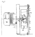
- the convection and steam oven 10 comprises an oven chamber 12, in which 14 plates 16 or grids are slidably guided in a known manner on slide rails.
- An adjoining room 20 is separated from the furnace room by a partition 18.
- This secondary room 20 is connected to the furnace chamber via circumferential slots 22 and a central opening 24.
- a radial fan 26 is arranged in the adjoining room 20 and has fan blades 28 arranged on a circular circumference.
- the fan 26 is flanged onto a hub 30 which is driven by a motor 32.
- a pre-atomizing element 34 is also arranged on the fan hub, over which a pipeline 36, into which water to be evaporated is introduced, ends.
- Heating coils 38 are placed around the fan 26 and are gas-heated or electrically heated, for example.
- the oven 10 can be operated as a convection oven in that, by means of the radial fan 26, air is passed over the heating coils 38, where it is heated.
- the heated air enters the furnace chamber 12 through the gap 22 surrounding the wall 18.
- the air is drawn in by the fan 26 out of the furnace space and deflected in the direction of the fan blades 28.
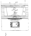
- FIGS. 2 to 8 Different embodiments of the pre-atomization element result from FIGS. 2 to 8.
- FIGS. 2 to 8 only the details essential for atomization are shown.
- the heating elements 38 have not been shown here, for example.
- a pre-atomizing element 34 which is composed of two hemispherical shells 40, is mounted on the fan shaft 30 driven by the motor 32, both hemispherical shells being delimited by a peripheral edge 42.
- the two hemispherical shells are integrally connected to one another along the edges 42 lying one on top of the other.
- a web is formed which surrounds the surface of the ball and which, as can be seen in FIG. 2, intersects the axis of rotation of the ball at an angle which in this exemplary embodiment is approximately 60 °.
- the hemispherical shells have two openings, one opening being adapted to the shaft extension of the fan rotation shaft 30. In the exemplary embodiment shown here in FIG.
- a fastening flange 46 for the fan 26 is seated on the shaft shoulder, to which the opening of the hemisphere shell 40 is then adapted.
- a screw 44 is guided through the other hemisphere shell 40 and can be screwed into a corresponding bore within the mounting flange 46 and thus fixes the sphere composed of the two hemisphere shells.
- the pipe 36 through which the water is fed onto the pre-atomizing element 34, opens out above the axis of rotation.
- the pipe is arranged parallel to the fan and in its end area bent towards the pre-atomizing element 34.
- the tube 36 ends approximately in the area of the outer edge of the fan 26, as shown in more detail in FIG. 2. In the exemplary embodiment shown in FIG.
- the atomizing element 34 extends almost over the entire depth of the fan 26. This corresponds to an embodiment which is intended in particular for smaller ovens 10.
- the fan 26 and thus also the pre-atomizing element 34 runs at speeds of approximately 2800 revolutions per minute.
- the overall dimensions of the small ovens are approx. 50 cm deep, 50 cm high and 70 cm wide. The external dimensions are given here accordingly.
- the embodiment according to FIG. 3 essentially corresponds to that according to FIG. 2. However, this is an embodiment in particular for comparatively larger stoves.
- the pre-atomizing element 34 here again consists of a ball with an encasing web, which again consists of hemispherical shells 40 and spherical bodies joined along the protruding edge 42.
- a cylinder extension 46 'aligned in the axis of rotation, over one side of which a screw bolt 48 is attached, to which the pre-atomizing element 34 is screwed into the fan flange 36.
- FIG. 4 essentially corresponds to that according to FIG. 3 and is also intended for comparatively larger stoves.
- the speed corresponds to that according to the embodiment according to FIG. 3.
- Ball 50 is provided, which has no enveloping web. Otherwise, this variant corresponds to that which has already been described with reference to FIG. 3.
- the embodiment variant according to FIG. 5 corresponds to that according to FIGS. 3 and 4 and is also preferably used for the large construction variant of the furnace.
- a ball with flattened surfaces is used as the pre-atomizing element 34.
- the pre-atomizing element 34 has the shape of a hemisphere. This is formed from a hemispherical shell 40 with a peripheral edge 42, to which a circular plate 52 is connected flush. On this plate 52 sits a cylinder extension 46 ', which is screwed into the fan flange 46 via a bolt 48 formed thereon. As shown in FIG. 6, the hemisphere is tilted with respect to the axis of rotation. The line of symmetry of the hemisphere forms an angle ⁇ of 15 ° with the axis of rotation.
- the water pipe 36 opens above the pre-atomizing element 34, as shown in FIG. 6.
- the embodiment according to FIG. 7 largely corresponds to the embodiment previously explained with reference to FIG. 6. Here, however, no edge is formed on the hemisphere shell 40 and the axis of symmetry of the hemisphere shell 40 coincides with the axis of rotation. Otherwise, the embodiment according to FIG. 7 corresponds to that according to FIG. 6.
- FIG. 1 Another variant of the atomizing device 34 is shown in FIG. There, a circular plate 60 is provided on a cylinder extension 46 'at an angle to the axis of rotation.
- the water supply pipe 36 opens above the outer periphery of the rotating plate 60 as shown in FIG.
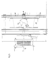
- FIGS. 9 to 12 show further alternatives for embodiments of a convection or steam oven according to the invention.
- the convection and steam oven comprises an oven space in which are guided in a known manner on sliding rails, sheets or grids.
- a side room is separated from the furnace room by a partition.
- This adjoining room is connected to the furnace room via circumferential slots and a central opening.
- a radially acting fan designated 26 in FIGS. 9-12, is arranged.
- This has fan blades 28 arranged on a circumference.
- the fan 26 is flanged onto a fan hub 30 which is driven by a rotor 32.
- a pre-atomizing element 34 is arranged on the fan axis, next to which the outlet opening of a pipeline 36 in which water to be evaporated is filled ends in the direction of the axis of rotation.
- heating coils 38 are placed, which are gas-heated or electrically heated, for example.
- the oven can be operated as a convection oven in which air is passed over the heating coils by means of the radial fan 26, where it is heated. The heated air enters the furnace chamber through the gap around the wall. In the area of the breakthrough, the air is drawn in by the fan from the furnace space and deflected in the direction of the fan blades 28.
- a pre-atomizing element 34 is mounted on the fan shaft 30 driven by the motor 32, which element is composed of two hemispherical shells 40, both hemispherical shells being delimited by a peripheral edge 42.
- the two hemispherical shells are integrally connected to one another along the edges 42 lying one on top of the other.
- a web is formed which surrounds the surface of the ball and which, as can be seen in FIG. 10, intersects the axis of rotation of the ball at an angle ⁇ , which in this exemplary embodiment is approximately 60 °.
- a pre-atomization element is thus formed here in the form of a ball, on the surface of which a web surrounding it is arranged.
- the outlet opening of the pipeline 36 is arranged next to the ball in the direction of the axis of rotation, as can be seen in FIG. 1.
- a rod 70 is attached to the side of the outlet opening of the pipeline facing the axis of rotation of the fan 26.
- the free end of the rod 70 extends approximately to the axis of rotation of the fan 26.
- the water drops emerging from the outlet opening of the pipeline 36 are guided via this rod in the direction of the pre-atomizing element 34. Otherwise, they are entrained by the axially inflowing air in the direction of the pre-atomization element.
- the pre-atomization element 34 has a flat 72, so that essentially a ball with a flat on one side results.
- the flat 72 is arranged opposite the outlet opening of the pipeline 36.
- FIGS. 11 and 11a A further modification of the pre-atomizing element is shown in FIGS. 11 and 11a.
- the web 42 enveloping the ball which is comparatively wider, has openings 74 along the circular ring forming the web.
- FIG. 12 shows another modification of the exemplary embodiment according to FIG. 9, which consists in that the spherical pre-atomizing element 34 has a recess 76 directed towards the inside of the sphere in the direction of the rotational axis and that the rod 70 extends into this recess.
- the pre-atomizing element 34 is designed in accordance with the embodiment according to FIG. 1.
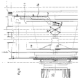
- the pipeline 36 is modified. 13
- the pipeline is pulled down parallel to the walls forming the furnace space to approximately the height of the line of symmetry of the pre-atomizing element 34 designed as a ball.
- the beveled tip of the pipeline 36 opens into a cup 80.
- the cup 80 has a bevelled edge 82 which points towards the pre-atomizing element 34.
- a portion of the border 82 can, as shown in FIG. 13, rest on the surface of the pre-atomizing element 34.
- the rubber cup 80 can be connected to the pipeline 36 via a clamping screw 84.
- This arrangement ensures that the water flowing in through the pipe 36 is brought into contact with the pre-atomizing element via the cavity of the cup. After the forced contact with the pre-atomization element 34, the latter is flung away from the surface of the pre-atomization element 34 and is thereby already atomized.
- FIG. 14 shows a modified form of a cup, which can be described as a tube piece 80 '.
- the pipe section 80 ' is funnel-shaped on the inside. This ensures that the water runs along the funnel widening towards the pre-atomizing element 34. This will direct the water to the pre-atomization element. The water is additionally dragged along by the air sucked in through the pipeline 80 ′, which is sucked in due to the ventilation effect of the fan 28.
- the pipe section is also connected to the pipe 36 via a clamping screw 84 '.
- the pipe section 80 ' is also made of rubber here.
- FIG. 15 An embodiment is shown in FIG. 15, in which the pipeline 36 also corresponds to the course as was shown in FIG. 1.
- a trough-shaped element 86 made of rubber is arranged below the outlet opening of the pipeline 36, which rests with an edge 88 on the surface of the pre-atomizing element 34.
- the trough-shaped element 86 is screwed onto the pipe 36 via a holding plate 90.
- the water emerging from the outlet opening of the pipeline 36 drops onto the trough-shaped element 86 and, as shown in FIG. 15, is forcibly brought into contact with the pre-atomizing element 34 by this.
Abstract
Description
Die Erfindung betrifft einen Konvektions- und Dampfofen für Lebensmittel mit einem Ofenraum und einem von diesem abgeteilten Nebenraum, in dem ein motorbetriebener radial wirkender Ventilator um mehrere diesen umgebende Heizelemente angeordnet sind, wobei auf der Nabe des Ventilators ein mit diesem rotierendes Vorzerstäubungselement für wahlweise aus einer Rohrleitung auf dieses geführtes Wasser angeordnet ist.The invention relates to a convection and steam oven for foodstuffs with an oven space and an adjoining room separated from it, in which a motor-driven, radially acting fan is arranged around a plurality of heating elements surrounding it, with a pre-atomizing element rotating therewith for optionally consisting of one on the hub of the fan Pipeline is arranged on this water.
Ein derartiger Konvektions- und Dampfofen für Lebensmittel ist beispielsweise schon aus der EP 244 538 B 1 bekannt. Für den Fall, daß dieser vorbekannte Ofen als Dampfofen betrieben werden soll, wird eine Dampfatmosphäre dadurch gebildet, daß das aus der Rohrleitung herausströmende Wasser in zwei Schritten zerstäubt wird und in dieser zerstäubten Form von der durch den Ventilator erzeugten radialen Luftströmung an den Heizelementen vorbeigeführt wird, wo es in die Dampfphase überführt wird. Die Dampfpartikel werden dann mit der durch den Ventilator erzeugten Strömung weiter mitgerissen. Die Endzerstäubung der noch nicht in Dampfform überführten Wasserpartikel erfolgt durch den radial wirkenden Ventilator. Die Vorzerstäubung wird gemäß diesem vorbekannten Stand der Technik dadurch erzeugt, daß auf der Drehachse des Ventilators ein mit dem Ventilator rotierendes geschlossenes Becherelement gebildet ist. In dieses Becherelement ist das Ende der Wasserzuführleitung geführt. Das rotierende Becherelement weist einen Randteil und eine Innenfläche auf, die vom Randteil weg umgekehrt konisch verläuft, so daß sich in dem Becher ein Wasservolumen sammeln kann und so daß nach Auffüllen des Wasservolumens das überschüssige Wasser über den Rand fließt und dadurch einen Wasserfilm bildet, der durch die Fliehkraft zerstäubt wird. Das so vorzerstäubte Wasser trifft dann auf die in einem Ring angeordneten Blätter des radial wirkenden Ventilators auf und wird dort noch weiter zerkleinert, wie zuvor erläutert.Such a convection and steam oven for food is already known, for example, from EP 244 538 B1. In the event that this previously known furnace is to be operated as a steam oven, a steam atmosphere is formed by atomizing the water flowing out of the pipeline in two steps and in this atomized form being guided past the heating elements by the radial air flow generated by the fan where it is transferred to the vapor phase. The steam particles are then carried along with the flow generated by the fan. The final atomization of the water particles, which have not yet been converted into vapor form, is carried out by the radially acting fan. The pre-atomization is known according to this State of the art produced in that a closed cup element rotating with the fan is formed on the axis of rotation of the fan. The end of the water supply line is guided into this cup element. The rotating cup element has an edge part and an inner surface that tapers away from the edge part so that a volume of water can collect in the cup and so that after filling up the water volume, the excess water flows over the edge and thereby forms a water film that is atomized by centrifugal force. The water which has been pre-atomized in this way then hits the blades of the radial-acting fan arranged in a ring and is further crushed there, as previously explained.
Auch aus der italienischen Gebrauchsmusteranmeldung 40 052A/90 ist ein gattungsgemäßer Konvektions- und Dampfofen bekannt. Im Gegensatz zu dem zuvor beschriebenen Konvektions- und Dampfofen ist hier im Ofenraum ein Überdruck aufgebaut, so daß der im Nebenraum gebildete und sich über den Ofenraum verteilende Dampf überhitzt werden kann. Darüber hinaus führt die Druckerhöhung im Ofenraum um ca. 5 mbar zu einer gleichmäßigeren Verteilung der Dampfatmosphäre. Das Vorzerstäubungselement ist hier durch eine auf der Achse des Ventilators mitrotierenden Trommel gebildet, die auf Umfang gleichmäßig verteilt eine Vielzahl von langlochartigen Durchbrüchen aufweist. Das Wasser wird von der Rohrleitung am offenen Ende der mit den Durchbrüchen versehenen Trommel aufgegeben. Durch die vom radial wirkenden Ventilator aus dem Zentrum angesaugte Luftströmung wird das aus dem Rohr austretende Wasser mitgerissen und durch die langlochartigen Öffnungen in der Trommelwandung geführt, wobei das Wasser an den langlochartigen Öffnungen zerstäubt wird. Im Unterschied zu dem vorbekannten Vorzerstäubungselement gemäß der EP 244 538 B1 wird hier nicht nur ein über die Kante eines Bechers abreißender Wasserfilm gebildet. Vielmehr wird hier über die gesamte Länge der Langlöcher ein Zerstäubungseffekt erreicht, so daß die so vorzerstäubten Wassertropfen gleichverteilt auf die Ventilatorblätter auftreffen. Hier wird also eine bessere Zerstäubung erreicht, da aufgrund eines anderen Wirkprinzips der Vorzerstäubung die ganze Tiefe des radial wirkenden kreisförmigen Ventilators ausgenutzt wird.A generic convection and steam oven is also known from the Italian
Allerdings weisen beide zuvor beschriebenen Ausführungsformen den Nachteil auf, daß sie nach verhältnismäßig kurzer Standzeit bereits verkalken und dann ausgewechselt werden müssen. Der Kalk setzt sich bevorzugt im Auslaufbereich des Rohres, also am offenen Ende des geschlossenen Bechers bzw. der mit Durchbrüchen versehenen Trommel an. Auch eine sich gegenüber der italienischen Gebrauchsmusteranmeldung unterscheidende realisierte Ausführungsform, in der die Trommel eine sich nach außen hin erweiternde konische Form aufweist, führt hier zu keiner Abhilfe. Die sich aufbauende Kalkschicht ist je nach Kalkgehalt des eingesetzten Wassers innerhalb kurzer Zeit so dick, daß die gesamte Vorrichtung nicht mehr funktionsfähig ist.However, both of the previously described embodiments have the disadvantage that they calcify after a relatively short service life and then have to be replaced. The lime deposits preferably in the outlet area of the pipe, that is to say at the open end of the closed cup or the drum provided with openings. Even a realized embodiment that differs from the Italian utility model application, in which the drum has a conical shape that widens outwards, does not lead to any remedy here. Depending on the lime content of the water used, the limescale layer that builds up is so thick within a short time that the entire device is no longer functional.
Aus der EP 233 535 B ist ebenfalls ein gattungsgemäßer Konvektions- und Dampfofen bekannt. Bei dieser Ausführung ist kein eigens gestaltetes Vorzerstäubungselement vorgesehen. Vielmehr wird hier das Wasser auf die Nabe des Ventilators aufgegeben. Dabei wird nach der Lehre dieses Patents die Austrittsöffnung der Wasserzuführung radial von außen auf die Nabe hin gerichtet und die Austrittsöffnung der Wasserzuführung ist oberhalb der Nabe angeordnet. Hierdurch erhofft man sich, daß das aus der Austrittsöffnung ausströmende Wasser von oben auf die mit dem Ventilator rotierende Nabe fallen kann und von dieser zerstäubt wird. Dieser vorbekannte Konvektions- und Dampfofen führt zu einer nicht befriedigenden Vorzerstäubungswirkung.A convection and steam oven of the generic type is also known from EP 233 535 B. In this version, no specially designed pre-atomizing element is provided. Rather, the water is applied to the fan hub. According to the teaching of this patent, the outlet opening of the water supply is directed radially from the outside towards the hub and the outlet opening of the water supply is arranged above the hub. This is hoped that the water flowing out of the outlet opening can fall from above onto the hub rotating with the fan and is atomized by the latter. This known convection and steam oven leads to an unsatisfactory pre-atomization effect.
Ausgehend von dem zuletzt genannten Stand der Technik ist es die Aufgabe der vorliegenden Erfindung, den gattungsgemäßen Konvektions- und Dampfofen derart weiterzubilden, daß eine bessere Vorzerstäubung des zu verdampfenden Wassers ermöglicht wird.Starting from the last-mentioned prior art, it is the object of the present invention to further develop the generic convection and steam oven in such a way that a better pre-atomization of the water to be evaporated is made possible.
Die erfindungsgemäße Lösung dieser Aufgabe ergibt sich ausgehend von dem gattungsgemäßen Konvektions- und Dampfofen aus dem kennzeichnenden Teil des Anspruchs 1. Demnach wird auf der Nabe des Ventilators ein eigens für die Vorzerstäubung geformtes Vorzerstäubungselement angeordnet. Dieses besteht aus einem Körper mit konvexer Oberfläche. Es wurde überraschend gefunden, daß das auf einen konvexen Körper auftropfende Wasser aufgrund der Rotationsbewegung dieses Körpers schon sehr fein vorzerstäubt wird. Entscheidend ist es hier, daß die sich auf dem Vorzerstäubungselement bildenden Kalkschichten nicht zu einem Verstopfen und zu einer Funktionsuntüchtigkeit führen, sondern sich auf der konvexen Oberfläche aufbauen und zu zusätzlichen Unregelmäßigkeiten auf der konvexen Oberfläche führen, die die Vorzerstäubungswirkung eher noch verbessern.The solution to this problem according to the invention arises from the generic convection and steam oven from the characterizing part of claim 1. Accordingly, a pre-atomization element specially formed for the pre-atomization is arranged on the hub of the fan. This consists of a body with a convex surface. It has surprisingly been found that the water dripping onto a convex body is already very finely atomized due to the rotational movement of this body. It is crucial here that the limescale layers forming on the pre-atomization element do not lead to clogging and inoperability, but build up on the convex surface and lead to additional irregularities on the convex surface, which rather improve the pre-atomization effect.
Gemäß einer bevorzugten Ausführungsform der Erfindung ist der konvexe Körper als Kugel ausgebildet. Auf der Oberfläche der Kugel kann ein die Kugel umhüllender Steg angeordnet sein, der die Rotationsachse der Kugel in einem Winkel (α) schneidet, der größer als 0° und kleiner als 90° ist. Durch diesen zusätzlichen Steg wird eine besonders gute Vorzerstäubung erreicht. Insbesondere die Verteilung der Wassertröpfchen über die gesamte Tiefe des Ventilatorrings ist hierdurch sichergestellt. In einer tieferen Bauform des radial wirkenden Ventilators für vergleichsweise größere Öfen kann die Kugel über ein Zylinderansatzstück auf der Antriebswelle des Ventilators befestigt sein.According to a preferred embodiment of the invention, the convex body is designed as a sphere. On the surface of the ball, a web enveloping the ball can be arranged which intersects the axis of rotation of the ball at an angle (α) which is greater than 0 ° and less than 90 °. Particularly good pre-atomization is achieved through this additional web. This ensures in particular the distribution of the water droplets over the entire depth of the fan ring. In a deeper design of the radially acting fan for comparatively larger ovens, the ball can be fastened to the drive shaft of the fan via a cylinder extension piece.
Die Austrittsöffnung der das zu verdampfende Wasser zuführenden Rohrleitung kann dabei in Richtung der Rotationsachse betrachtet neben der Kugel angeordnet sein und axial auf die Kugel hin gerichtet sein. Damit werden die aus der Austrittsöffnung herausströmenden Wassertropfen von der axial in das Lüfterrad hineinströmenden Luftströmung erfaßt und auf das entsprechend geformte Vorzerstäubungselement hin geleitet.The outlet opening of the water to be evaporated When viewed in the direction of the axis of rotation, the pipeline can be arranged next to the ball and directed axially towards the ball. The water drops flowing out of the outlet opening are thus caught by the air flow flowing axially into the fan wheel and directed to the correspondingly shaped pre-atomizing element.
Besonders vorteilhaft kann die Kugel aus zwei Halbkugelschalen zusammengesetzt sein, wobei beide Halbkugelschalen von einem umlaufenden Rand begrenzt werden. Die beiden Halbkugelschalen können entlang der aufeinanderliegenden Ränder miteinander stoffschlüssig und/oder formschlüssig verbunden werden. Hier wird in sehr einfacher Art und Weise eine Kugel an die Hand gegeben, die den zuvor genannten umhüllenden Steg aufweist.The ball can particularly advantageously be composed of two hemispherical shells, with both hemispherical shells being delimited by a peripheral edge. The two hemispherical shells can be connected to one another in a cohesive and / or positive manner along the edges lying one on top of the other. Here a ball is given in a very simple manner, which has the above-mentioned enveloping web.
Für eine weniger tief bauende Ausführung können die Halbkugelschalen in vorteilhafter Art und Weise zwei Durchbrüche aufweisen, wobei der eine Durchbruch an einen Wellenansatz der Ventilatorrotationswelle angepaßt ist und wobei durch den anderen Durchbruch eine Montageschraube zur Montage der Kugel geführt ist. Bei dieser Bauausführung wird auf das Zylinderansatzstück das zuvor erwähnt wurde, verzichtet.For a less deep construction, the hemispherical shells can advantageously have two openings, one opening being adapted to a shaft extension of the fan rotation shaft and a mounting screw for mounting the ball being guided through the other opening. In this construction, the cylinder extension that was mentioned earlier is dispensed with.
In einer weiteren Ausgestaltung der Erfindung kann die Oberfläche der Kugel teilweise abgeflacht sein.In a further embodiment of the invention, the surface of the ball can be partially flattened.
Das Vorzerstäubungselement kann gemäß einer alternativen Ausführungsform der Erfindung auch aus einer Halbkugel bestehen. Dabei kann die Symmetrielinie der Halbkugel einerseits mit der Rotationsachse zusammenfallen. Die Symmetrielinie der Halbkugel kann aber auch unter einem Winkel (β) zu der Rotationsachse angestellt sein.According to an alternative embodiment of the invention, the pre-atomizing element can also consist of a hemisphere. The line of symmetry of the hemisphere can coincide with the axis of rotation. The line of symmetry of the hemisphere can also be set at an angle (β) to the axis of rotation.
In vorteilhafter Weise läßt sich die Halbkugel aus einer Halbkugelschale mit umlaufenden Rand und einer mit diesem umlaufenden Rand bündig abschließenden und stoffschlüssig mit diesem verbundenen kreisrunden Platte herstellen.The hemisphere can advantageously be produced from a hemisphere shell with a peripheral edge and a circular plate which is flush with this peripheral edge and is integrally connected to it.
Eine weitere selbstständige Lösung der eingangs gestellten Aufgabe besteht darin, daß ein gattungsgemäßer Konvektions- und Dampfofen als Vorzerstäubungselement eine schräg zur Rotationsachse des Ventilators angestellte, vorzugsweise kreisrunde Platte aufweist, oberhalb derer die Rohrleitung endet. Mit dieser Ausführungsform wird insbesonder bei weniger tief bauenden Radialventilatoren eine gleichmäßige Verteilung über die Tiefe des Ventilatorrings erzielt.Another independent solution to the problem set out at the outset is that a generic convection and steam oven as a pre-atomizing element has a preferably circular plate which is positioned obliquely to the axis of rotation of the fan and above which the pipeline ends. With this embodiment, a uniform distribution over the depth of the fan ring is achieved in particular with radial fans of less depth.
Gemäß einer bevorzugten Ausführungsform kann an der zur Rotationsachse des Ventilators gerichteten Seite der Austrittsöffnung der Rohrleitung ein Stab, eine Zunge oder ein weiteres Rohr angesetzt sein. Der Stab, die Zunge oder das weitere Rohr dienen zur weiteren Führung der Tropfen, da die aus der Rohrleitung austretenden Tropfen entlang des Stabes, der Zunge oder des zusätzlichen Rohres abperlen und vom Stab, der Zunge oder dem zusätzlichen Rohr zu dem Vorzerstäubungselement hin geführt werden. Vorteilhaft reicht das freie Ende des Stabes, der Zunge oder des weiteren Rohres ungefähr bis zur Rotationsachse des Ventilators. Gemäß einer vorteilhaften Ausführungsform kann der Stab, die Zunge oder das weitere Rohr elastisch sein und gegebenenfalls aus Gummi bestehen. Unter Zunge ist auch eine Rinne zu verstehen, die gegebenenfalls elastisch ausgebildet sein kann und/oder schwingend am Rohr aufgehängt sein kann. Eine alternative Ausführungsform besteht darin, daß der Stab aus Metall besteht.According to a preferred embodiment, a rod, a tongue or a further tube can be attached to the side of the outlet opening of the pipeline facing the axis of rotation of the fan. The rod, the tongue or the further tube serve to further guide the drops, since the drops emerging from the pipeline roll off along the rod, the tongue or the additional tube and are guided from the rod, the tongue or the additional tube to the pre-atomizing element . The free end of the rod, the tongue or the further tube advantageously extends approximately up to the axis of rotation of the fan. According to an advantageous embodiment, the rod, the tongue or the further tube can be elastic and optionally made of rubber. The tongue is also to be understood as a channel, which can optionally be elastic and / or can be suspended in a swinging manner on the tube. An alternative embodiment is that the rod is made of metal.
Diese besondere Ausgestaltung der Erfindung ermöglicht einen weiteren zusätzlichen Zerstäubungsmechanismus. So werden die Tropfen, die über den Stab, die Zunge oder das Rohr geleitet werden und mit dem rotierenden Element in Berührung kommen bereits primär vorzerstäubt. Die Rotation des Vorzerstäubungselements führt zu einer weiteren Zerstäubung.This particular embodiment of the invention enables a further additional atomization mechanism. So the drops, which are passed over the rod, the tongue or the pipe and come into contact primarily with the rotating element. The rotation of the pre-atomization element leads to further atomization.
Das eine Ende der Kugel kann abgeflacht sein, wobei die Abflachung der Austrittsöffnung der Rohrleitung gegenüberliegt. Somit kann die Ebene der Austrittsöffnung parallel zu der Ebene der Abflachung ausgebildet sein. Die Rohraustrittsöffnung kann aber auch angeschrägt sein.One end of the ball can be flattened, the flattening being opposite the outlet opening of the pipeline. The plane of the outlet opening can thus be formed parallel to the plane of the flattening. The pipe outlet opening can also be chamfered.
Gemäß einer weiteren Ausführungsform der Erfindung kann die Kugel in der Rotationsachse eine ins Kugelinnere gerichtete Ausnehmung aufweisen, wobei der Stab in diese Ausnehmung hineinreicht. Hierdurch wird das Überführen der auf das Vorzerstäubungselement hinzuleitenden Wassertropfen weiter verbessert.According to a further embodiment of the invention, the ball in the axis of rotation can have a recess directed into the inside of the ball, the rod extending into this recess. This further improves the transfer of the water drops to be directed onto the pre-atomization element.
Eine besondere Ausführungsform der Erfindung besteht darin, daß die Rohrleitung bis in die Höhe der Rotationsachse des Ventilators heruntergezogen ist und erst ungefähr in der Höhe der Rotationsachse des Ventilators ein zum Vorzerstäubungselement offener Becher angesetzt ist. Dabei können sich die Symmetrieachsen des Vorzerstäubungselements und des Bechers ungefähr unter einem rechten Winkel schneiden. Die Rohrleitung und der angesetzte Becher sind derart ausgeführt, daß das Wasser über die Rohrleitung in den mit dieser verbundenen Becher läuft, der dieses in unmittelbarer Nähe des Vorzerstäubungselementes leitet.A special embodiment of the invention is that the pipeline is pulled down to the level of the axis of rotation of the fan and a cup open to the pre-atomizing element is only attached approximately at the level of the axis of rotation of the fan. The axes of symmetry of the pre-atomization element and the cup can intersect at approximately a right angle. The pipeline and the attached cup are designed such that the water runs through the pipeline into the cup connected to it, which guides it in the immediate vicinity of the pre-atomizing element.
Der Becher kann vorzugsweise aus Gummi oder Kunststoff, wie beispielsweise Teflon, PTFE, bestehen. Der offene Rand des Bechers kann angeschrägt sein und ein Teil des Randes kann unmittelbar neben dem Vorzerstäubungselement angeordnet sein.The cup can preferably be made of rubber or plastic, such as Teflon, PTFE. The open edge of the cup can be beveled and part of the edge can be arranged directly next to the pre-atomizing element.
Anstelle des Bechers kann aber auch ein an beiden Enden offenes Rohr in der Rohrleitung angesetzt sein. Dabei kann dieses eine trichterförmig verlaufende Innenwandung aufweisen, wobei sich der Innendurchmesser zum Vorzerstäubungselement hin erweitert. Hierdurch wird gewährleistet, daß das aus der Rohrleitung in das offene Rohr eintretende Wasser zum Vorzerstäubungselement hin fließt. Die Ausführung als offenes Rohr hat gegenüber dem einseitig geschlossenen Becher den Vorteil, daß durch den Ventilator angesaugte Luft durch das Rohr in Richtung zum Vorzerstäubungselement hin strömt.Instead of the cup, a pipe open at both ends can also be attached in the pipeline. This can have a funnel-shaped inner wall, the inner diameter widening toward the pre-atomizing element. This ensures that the water entering the open pipe from the pipeline flows towards the pre-atomizing element. The design as an open tube has the advantage over the cup closed on one side that air sucked in by the fan flows through the tube in the direction of the pre-atomizing element.
Falls die Austrittsöffnung der Rohrleitung in Rotationsrichtung neben der Kugel angeordnet ist und axial auf die Kugel hingerichtet ist, wobei die Austrittsöffnung der Rohrleitung oberhalb des Vorzerstäubungselements liegt, kann unterhalb der Austrittsöffnung im Bereich der Symmetrieachse des Vorzerstäubungselementes eine Auffangwanne angeordnet sein, deren unterer Rand nahe dem Vorzerstäubungselement endet. Dabei wird diese Auffangwanne vorteilhaft über ein elastisches Halteelement an die Rohrleitung angeschraubt.If the outlet opening of the pipeline is arranged next to the ball in the direction of rotation and is axially directed towards the ball, the outlet opening of the pipe lying above the pre-atomizing element, a collecting trough can be arranged below the outlet opening in the region of the axis of symmetry of the pre-atomizing element, the lower edge of which near the Pre-atomization element ends. This collecting trough is advantageously screwed onto the pipeline via an elastic holding element.
Weitere Einzelheiten und Vorteile der Erfindung werden anhand mehrerer in der Zeichnung dargestellter Ausführungsbeispiele erläutert. Es zeigen:
- Fig. 1:
- eine schematische Schnittdarstellung eines erfindungsgemäßen Konvektions- und Dampfofens für Lebensmittel in einer Ausführungsform und
- Fig. 2-15:
- vereinfachte Detaildarstellungen im Schnitt des Dampferzeugungssystems gemäß unterschiedlicher Ausführungsvarianten des erfindungsgemäßen Konvenktions- und Dampfofens für Lebensmittel.
- Fig. 1:
- is a schematic sectional view of a convection and steam oven according to the invention for food in one embodiment and
- Fig. 2-15:
- Simplified detailed representations in section of the steam generating system according to different design variants of the convection and steam oven for food according to the invention.
Der Konvektions- und Dampfofen 10 umfaßt einen Ofenraum 12, in dem in bekannter Art und Weise auf Gleitschienen 14 Bleche 16 oder Roste verschiebbar geführt sind. Über eine Trennwand 18 ist ein Nebenraum 20 vom Ofenraum abgeteilt. Dieser Nebenraum 20 steht über umlaufende Schlitze 22 und einen zentralen Durchbruch 24 mit dem Ofenraum in Verbindung. Im Nebenraum 20 ist ein radial wirkender Ventilator 26 angeordnet, der auf einem Kreisumfang angeordnete Ventilatorblätter 28 aufweist. Der Ventilator 26 ist auf eine Nabe 30 geflanscht, die über einen Motor 32 angetrieben wird. Ebenfalls auf der Ventilatornabe ist ein Vorzerstäubungselement 34 angeordnet, über dem eine Rohrleitung 36, in der zu verdampfendes Wasser eingeführt wird, endet. Um den Ventilator 26 herum sind Heizschlangen 38 gelegt, die beispielsweise gasbeheizt oder elektrisch beheizt sind. Der Ofen 10 kann als Konvektionsofen betrieben werden, indem mittels des radial wirkenden Ventilators 26 Luft über die Heizsschlangen 38 geführt wird, wo sie erhitzt wird. Die erhitzte Luft tritt durch den um die Wandung 18 umlaufenden Spalt 22 in den Ofenraum 12 ein. Im Bereich des Durchbruchs 24 wird die Luft vom Ventilator 26 aus dem Ofenraum angesaugt und in Richtung der Ventilatorblätter 28 umgelenkt.The convection and steam oven 10 comprises an
Bei der Betriebsweise als Dampfofen wird zusätzlich Wasser aus der Rohrleitung 36 auf das rotierende Vorzerstäubungselement 34 geleitet, wo es in feine Tröpfchen dispergiert wird, die sich über die Tiefe des Ventilators 26 verteilen. Diese vorzerstäubten Tröpfchen werden von der zu den Ventilatorblättern 28 umgelenkten Luftströmungen mitgerissen und prallen gegen die Ventilatorblätter 28, wo sie zum zweitenmal dispergiert und damit fein zerstäubt werden. Die so fein zerstäubten Wasserpartikel werden an den Heizelementen 38 vorbeigeführt und treten dort in die Dampfphase über. Der Dampf wird mittels des Luftstroms über den Ofenraum 12 gleich verteilt. Besonders vorteilhaft für die Dampfverteilung ist es in der hier gezeigten Ausführungsform, daß der Ofenraum 12 unter einem Überdruck von 3 bis 8 mbar gehalten ist.When operating as a steam oven, water is additionally conducted from the
Aus den Figuren 2 bis 8 ergeben sich unterschiedliche Ausführungsformen für das Vorzerstäubungselement. In den Figuren 2 bis 8 sind jeweils nur die für die Zerstäubung wesentlichen Details dargestellt. Aus Vereinfachungsgründen sind beispielsweise die Heizelemente 38 hier nicht mehr dargestellt worden.Different embodiments of the pre-atomization element result from FIGS. 2 to 8. In FIGS. 2 to 8 only the details essential for atomization are shown. For reasons of simplification, the
In Figur 2 ist auf der durch den Motor 32 angetriebenen Ventilatorwelle 30 ein Vorzerstäubungselement 34 montiert, das aus zwei Halbkugelschalen 40 zusammengesetzt ist, wobei beide Halbkugelschalen von einem umlaufenden Rand 42 begrenzt werden. Die beiden Halbkugelschalen sind entlang der aufeinanderliegenden Ränder 42 miteinander stoffschlüssig verbunden. Entlang dieser stoffschlüssig miteinander verbundenen Ränder ist ein die Oberfläche der Kugel umhüllender Steg gebildet, der, wie der Figur 2 zu entnehmen ist, die Rotationsachse der Kugel in einem Winkel schneidet, der in diesem Ausführungsbeispiel ca. 60° beträgt. Die Halbkugelschalen weisen zwei Durchbrüche auf, wobei der eine Durchbruch an den Wellenansatz der Ventilatorroationswelle 30 angepaßt ist. Im hier in Figur 2 dargestellten Ausführungsbeispiel sitzt auf dem Wellenansatz ein Befestigungsflansch 46 für den Ventilator 26, an den dann der Durchbruch der Halbkugelschale 40 angepaßt ist. Durch die andere Halbkugelschale 40 ist eine Schraube 44 geführt, die in eine entsprechende Bohrung innerhalb des Montageflansches 46 eindrehbar ist und so die aus den beiden Halbkugelschalen zusammengesetzte Kugel fixiert. Oberhalb der Rotationsachse mündet die Rohrleitung 36, durch die das Wasser auf das Vorzerstäubungselement 34 aufgegeben wird. Dabei ist das Rohr parallel zum Ventilator angeordnet und in seinem Endbereich zu dem Vorzerstäubungselement 34 hin gebogen. Das Rohr 36 endet ungefähr im Bereich der Außenkante des Ventilators 26, wie in Figur 2 näher dargestellt. In dem in Figur 2 dargestellten Ausführungsbeispiel erstreckt sich das Zerstäubungselement 34 beinahe über die ganze Tiefe des Ventilators 26. Dies entspricht einer Ausführungsform, die insbesondere für kleinere Öfen 10 gedacht ist. Hier läuft der Ventilator 26 und damit auch das Vorzerstäubungselement 34 mit Drehzahlen um ca. 2800 Umdrehungen pro Minute. Die Gesamtabmessung der kleinen Öfen ist ca. 50 cm Tiefe, 50 cm Höhe und 70 cm Breite. Hier sind entsprechend die Außenmaße angegeben.In FIG. 2, a
Die Ausführungsform gemäß Figur 3 entspricht im wesentlichen derjenigen gemäß Figur 2. Allerdings handelt es sich hier um eine Ausführungsform insbesondere für vergleichsweise größere Öfen. Das Vorzerstäubungselement 34 besteht hier wiederum aus einer Kugel mit umhüllenden Steg, der ebenfalls wieder aus Halbkugelschalen 40 und entlang des überstehenden Rands 42 zusammengefügtem Kugelkörper besteht. Hier ist allerdings ein in der Rotationsachse ausgerichtetes Zylinderansatzstück 46' vorgesehen, über dessen einer Seite ein Schraubbolzen 48 angesetzt ist, an den das Vorzerstäubungselement 34 in den Ventilatorflansch 36 eingeschraubt ist. Das Rohr 36 zur Zuführung des Wassers endet hier innerhalb des Ventilators 26 oberhalb des Kugelkörpers wie in Figur 3 dargestellt. Bei dieser Bauausführung läuft der Ventilator 26 mit Umdrehungen von 700 Umdrehungen pro Minute bis 1400 Umdrehungen pro Minute um.The embodiment according to FIG. 3 essentially corresponds to that according to FIG. 2. However, this is an embodiment in particular for comparatively larger stoves. The
Die in Figur 4 dargestellte alternative Ausführungsform entspricht im wesentlichen derjenigen gemäß Figur 3 und ist auch für vergleichsweise größer bauende Öfen vorgesehen. Die Drehzahl entspricht derjenigen gemäß der Ausführungsform nach Figur 3. Hier ist allerdings als Vorzerstäubungselement 34 eine einfache Kugel 50 vorgesehen, die keinen umhüllenden Steg aufweist. Ansonsten entspricht diese Ausführungsvariante derjenigen, die bereits unter Bezugnahme auf Figur 3 beschrieben wurde.The alternative embodiment shown in FIG. 4 essentially corresponds to that according to FIG. 3 and is also intended for comparatively larger stoves. The speed corresponds to that according to the embodiment according to FIG. 3. Here, however, a
Die Ausführungsvariante gemäß der Figur 5 entspricht denjenigen gemäß der Figur 3 und 4 und wird auch bevorzugt für die große Bauvariante des Ofens eingesetzt. Hier ist allerdings eine Kugel mit abgeflachten Oberflächen als Vorzerstäubungselement 34 eingesetzt.The embodiment variant according to FIG. 5 corresponds to that according to FIGS. 3 and 4 and is also preferably used for the large construction variant of the furnace. Here, however, a ball with flattened surfaces is used as the
In der in Figur 6 dargestellten Ausführungsform weist das Vorzerstäubungselement 34 die Form einer Halbkugel auf. Diese ist aus einer Halbkugelschale 40 mit umlaufenden Rand 42 gebildet, mit der bündig abschließend eine kreisrunde Platte 52 verbunden ist. An dieser Platte 52 sitzt ein Zylinderansatzstück 46' an, das über einen an diesem angeformten Bolzen 48 in den Ventilatorflansch 46 eingeschraubt ist. Wie in der Figur 6 dargestellt, ist die Halbkugel gegenüber der Rotationsachse gekippt. Die Symmetrielinie der Halbkugel bildet dabei mit der Rotationsachse einen Winkel β von 15°. Das Wasserrohr 36 mündet oberhalb des Vorzerstäubungselements 34, wie in Figur 6 gezeigt.In the embodiment shown in FIG. 6, the
Die Ausführungsform gemäß der Figur 7 entspricht weitgehend der zuvor anhand der Figur 6 erläuterten Ausführungsform. Hier ist allerdings an der Halbkugelschale 40 kein Rand angeformt und die Symmetrieachse der Halbkugelschale 40 fällt mit der Rotationsachse zusammen. Ansonsten entspricht die Ausführungsform gemäß der Figur 7 derjenigen gemäß der Figur 6.The embodiment according to FIG. 7 largely corresponds to the embodiment previously explained with reference to FIG. 6. Here, however, no edge is formed on the
Eine weiter Ausführungsvariante der Zerstäubungseinrichtung 34 ist in Figur 8 dargestellt. Dort ist an einem Zylinderansatzstück 46' eine schräg zur Rotationsachse angestellte kreisrunde Platte 60 vorgesehen. Das Wasserzuführrohr 36 mündet oberhalb des Außenumfangs der rotierenden Platte 60, wie in Figur 9 dargestellt.Another variant of the
In den Figuren 9 bis 12 sind weitere Alternativen für erfindungsgemäße Ausführungsformen eines Konvektions- oder Dampfofens dargestellt. Wie auch bei den vorhergehenden Ausführungsformen gezeigt, umfaßt der Konvektions- und Dampfofen einen Ofenraum, in dem in bekannter Art und Weise auf Gleitschienen, Bleche oder Roste verschiebbar geführt sind. Über eine Trennwand ist ein Nebenraum vom Ofenraum abgeteilt. Dieser Nebenraum steht über umlaufende Schlitze und einen zentralen Durchbruch mit dem Ofenraum in Verbindung. Im Nebenraum ist ein radial wirkender Ventilator, der in den Fig. 9-12 mit 26 bezeichnet ist, angeordnet. Dieser weist auf einem Kreisumfang angeordnete Ventilatorblätter 28 auf. Der Ventilator 26 ist auf eine Ventilatornabe 30 geflanscht, die über einen Rotor 32 angetrieben wird. Ebenfalls auf der Ventilatorachse ist ein Vorzerstäubungselement 34 angeordnet, neben dem in Richtung der Rotationsachse die Austrittsöffnung einer Rohrleitung 36, in der zu verdampfendes Wasser eingefüllt wird, endet. Um den Ventilator 26 herum sind, wie in den Zeichnungen nicht näher dargestellt ist, Heizschlangen 38 gelegt, die beispielsweise gasbeheizt oder elektrisch beheizt sind. Der Ofen kann als Konvektionsofen betrieben werden, in dem mittels des radial wirkenden Ventilators 26 Luft über die Heizschlangen geführt wird, wo sie erhitzt wird. Die erhitzte Luft tritt durch den um die Wandung verlaufenden Spalt in den Ofenraum ein. Im Bereich des Durchbruchs wird die Luft vom Ventilator aus dem Ofenraum angesaugt und in Richtung der Ventilatorblätter 28 umgelenkt.FIGS. 9 to 12 show further alternatives for embodiments of a convection or steam oven according to the invention. As also shown in the previous embodiments, the convection and steam oven comprises an oven space in which are guided in a known manner on sliding rails, sheets or grids. A side room is separated from the furnace room by a partition. This adjoining room is connected to the furnace room via circumferential slots and a central opening. In the adjoining room, a radially acting fan, designated 26 in FIGS. 9-12, is arranged. This has
Bei der Betriebsweise als Dampfofen wird zusätzlich Wasser aus der Rohrleitung 36 auf das rotierende Vorzerstäubungselement 34 geleitet, wo es in feine Tröpfchen dispergiert wird, die sich über die Tiefe des Ventilators 26 verteilen. Diese vorzerstäubten Tröpfchen werden von der zu den Ventilatorblättern 28 umgelenkten Luftströmung mitgerissen und prallen gegen die Ventilatorblätter 28, wo sie zum zweitenmal dispergiert werden und damit fein zerstäubt werden. Die so fein zerstäubten Wasserpartikel werden an den hier nicht näher dargestellten Heizelementen vorbeigeführt und treten dort in die Dampfphase über. Der Dampf wird mittels des Luftstroms über dem Ofenraum gleich verteilt. Besonders vorteilhaft für die Dampfverteilung ist es in der hier gezeigten Ausführungsform, daß der Ofenraum über einem Überdruck von 3-8 mbar gehalten ist. Aus den Fig. 9-12 ergeben sich nun unterschiedliche Ausführungsformen für das Vorzerstäubungselement.When operating as a steam oven, water is additionally conducted from the
In Fig. 9 ist auf der durch den Motor 32 angetriebenen Ventilatorwelle 30 ein Vorzerstäubungselement 34 montiert, das aus zwei Halbkugelschalen 40 zusammengesetzt ist, wobei beide Halbkugelschalen von einem umlaufenden Rand 42 begrenzt werden. Die beiden Halbkugelschalen sind entlang der aufeinanderliegenden Ränder 42 miteinander stoffschlüssig verbunden. Entlang dieser stoffschlüssig miteinander verbundenen Ränder ist ein die Oberfläche der Kugel umhüllender Steg gebildet, der, wie der Fig. 10 zu entnehmen ist, die Rotationsachse der Kugel in einem Winkel α schneidet, der in diesem Ausführungsbeispiel ca. 60° beträgt. Somit wird hier ein Vorzerstäubungselement in Form einer Kugel gebildet, auf deren Oberfläche ein sie umhüllender Steg angeordnet ist. Die Austrittsöffnung der Rohrleitung 36 ist in Rotationsachsrichtung neben der Kugel angeordnet, wie der Fig. 1 zu entnehmen ist. An der zur Rotationsachse des Ventilators 26 gerichteten Seite der Austrittsöffnung der Rohrleitung ist ein Stab 70 angesetzt. Das freie Ende des Stabs 70 reicht ungefähr bis zur Rotationsachse des Ventilators 26. Über diesen Stab werden die aus der Austrittsöffnung der Rohrleitung 36 austretenden Wassertropfen in Richtung zum Vorzerstäubungselement 34 hin geführt. Im übrigen werden sie durch die axial einströmende Luft in Richtung zum Vorzerstäubungselement hin mitgerissen.In FIG. 9, a
Die Ausführungsform gemäß Fig. 10 entspricht weitgehend derjenigen gemäß Fig. 1, so daß die einzelnen Merkmale hier nicht nochmals wiederholt werden. Im Unterschied zu der Ausführungsform gemäß Fig. 1 weist jedoch das Vorzerstäubungselement 34 eine Abflachung 72 auf, so daß sich im wesentlichen eine Kugel mit einseitiger Abflachung ergibt. Die Abflachung 72 ist der Austrittsöffnung der Rohrleitung 36 gegenüber angeordnet.The embodiment according to FIG. 10 largely corresponds to that according to FIG. 1, so that the individual features are not repeated here. In contrast to the embodiment according to FIG. 1, however, the
In den Fig. 11 und 11a ist eine weitere Modifikation des Vorzerstäubungselements dargestellt. Hier weist der die Kugel umhüllende Steg 42, der vergleichsweise breiter ausgeführt ist, entlang des den Steg bildenden Kreisrings Durchbrüche 74 auf. Diese führen zu einer weiteren Verbesserung der Zerstäubung.A further modification of the pre-atomizing element is shown in FIGS. 11 and 11a. Here, the
Schließlich zeigt die Fig. 12 eine andere Modifikation des Ausführungsbeispiels gemäß Fig. 9, die darin besteht, daß das kugelförmige Vorzerstäubungselement 34 eine in Rotationsachsrichtung ins Kugelinnere hin gerichtete Ausnehmung 76 aufweist und daß der Stab 70 bis in diese Ausnehmung hinein reicht.Finally, FIG. 12 shows another modification of the exemplary embodiment according to FIG. 9, which consists in that the spherical
Gemäß dem Ausführungsbeispiel nach Fig. 13 ist das Vorzerstäubungselement 34 entsprechend der Ausführungsform gemäß Fig. 1 ausgebildet. In diesem Ausführungsbeispiel ist allerdings die Rohrleitung 36 modifiziert. Entsprechend der Darstellung gemäß Fig. 13 wird die Rohrleitung parallel zu den den Ofenraum bildenden Wandungen bis ungefähr in Höhe der Symmetrielinie des als Kugel ausgebildeten Vorzerstäubungselements 34 heruntergezogen. Die angeschrägte Spitze der Rohrleitung 36 mündet in einem Becher 80. Der Becher 80 hat einen angeschrägten Rand 82, der zum Vorzerstäubungselement 34 hin weist. Ein Teilbereich des Randes 82 kann, wie in Fig. 13 dargestellt, an der Oberfläche des Vorzerstäubungselements 34 anliegen. Der Becher aus Gummi 80 kann über eine Klemmschraube 84 mit der Rohrleitung 36 verbunden sein. Durch diese Anordnung wird gewährleistet, daß das durch die Rohrleitung 36 einströmende Wasser über den Hohlraum des Bechers mit dem Vorzerstäubungselement in Kontakt gebracht wird. Nach dem zwangsweisen Kontakt mit dem Vorzerstäubungselement 34 wird dieses von der Oberfläche des Vorzerstäubungselements 34 weggeschleudert und dadurch bereits zerstäubt.According to the exemplary embodiment according to FIG. 13, the
In Fig. 14 ist eine modifizierte Form eines Bechers, die eher als Rohrstück 80' beschrieben werden kann, dargestellt. Das Rohrstück 80' ist innen trichterförmig ausgebildet. Hierdurch wird gewährleistet, daß das Wasser entlang des sich zum Vorzerstäubungselement 34 hin erweiternden Trichters läuft. Dadurch wird das Wasser auf das Vorzerstäubungselement geleitet. Das Wasser wird dabei zusätzlich durch die durch die Rohrleitung 80' angesaugte Luft, die aufgrund der Ventilationswirkung des Ventilators 28 angesaugt wird, mitgeschleppt. Auch das Rohrstück wird über eine Klemmschraube 84' mit der Rohrleitung 36 verbunden. Das Rohrstück 80' besteht hier ebenfalls aus Gummi.FIG. 14 shows a modified form of a cup, which can be described as a tube piece 80 '. The pipe section 80 'is funnel-shaped on the inside. This ensures that the water runs along the funnel widening towards the
In Fig. 15 ist eine Ausführungsform dargestellt, bei der die Rohrleitung 36 auch den Verlauf, wie er in Fig. 1 dargestellt wurde, entspricht. Hier ist allerdings unterhalb der Austrittsöffnung der Rohrleitung 36 ein wannenförmiges Element 86 aus Gummi angeordnet, das mit einem Rand 88 an der Oberfläche des Vorzerstäubungselements 34 anliegt. Das wannenförmige Element 86 ist über ein Halteblech 90 an der Rohrleitung 36 angeschraubt. Das aus der Austrittsöffnung der Rohrleitung 36 austretende Wasser tropft auf das wannenförmige Element 86 und wird von diesem, wie in Fig. 15 dargestellt, zwangsweise mit dem Vorzerstäubungselement 34 in Kontakt gebracht.An embodiment is shown in FIG. 15, in which the
Claims (23)
dadurch gekennzeichnet,
daß das Vorzerstäubungselement als separater Körper mit einer konvexen Oberfläche auf der Nabe des Ventilators angeordnet ist.Convection and steam oven for food with an oven space and a separate room separated from it, in which a motor-driven, radially acting fan and several heating elements surrounding it are arranged, with on the hub of the fan rotating with this pre-atomizing element for optionally from a pipe on this water is arranged,
characterized,
that the pre-atomizing element is arranged as a separate body with a convex surface on the hub of the fan.
Priority Applications (1)
| Application Number | Priority Date | Filing Date | Title |
|---|---|---|---|
| US08/286,749 US5530223A (en) | 1993-08-05 | 1994-08-05 | Convection and steam oven with a pre-atomizer |
Applications Claiming Priority (6)
| Application Number | Priority Date | Filing Date | Title |
|---|---|---|---|
| DE9311711U | 1993-08-05 | ||
| DE19939311711 DE9311711U1 (en) | 1993-08-05 | 1993-08-05 | Convection and steam oven for food |
| DE9316958U | 1993-11-05 | ||
| DE9316958 | 1993-11-05 | ||
| DE9402624U DE9402624U1 (en) | 1993-11-05 | 1994-02-17 | Convection and steam oven for food |
| DE9402624U | 1994-02-17 |
Publications (2)
| Publication Number | Publication Date |
|---|---|
| EP0640310A1 true EP0640310A1 (en) | 1995-03-01 |
| EP0640310B1 EP0640310B1 (en) | 1998-11-04 |
Family
ID=27208620
Family Applications (1)
| Application Number | Title | Priority Date | Filing Date |
|---|---|---|---|
| EP94107706A Expired - Lifetime EP0640310B1 (en) | 1993-08-05 | 1994-05-18 | Steam convection oven for food preparation |
Country Status (5)
| Country | Link |
|---|---|
| EP (1) | EP0640310B1 (en) |
| AT (1) | ATE172857T1 (en) |
| DE (1) | DE59407216D1 (en) |
| DK (1) | DK0640310T3 (en) |
| ES (1) | ES2124337T3 (en) |
Cited By (7)
| Publication number | Priority date | Publication date | Assignee | Title |
|---|---|---|---|---|
| WO1997033479A1 (en) * | 1996-03-12 | 1997-09-18 | Aktiebolaget Electrolux | A generator for steam |
| EP0893084A1 (en) | 1997-07-23 | 1999-01-27 | Gaggenau Hausgeräte GmbH | Steam cooking oven with a steam-generator |
| FR2775760A1 (en) * | 1998-03-09 | 1999-09-10 | Bourgeois Prod Coop | STEAM OVEN WITH FIXED SPRAY OF SPRAY WATER |
| WO2003046438A1 (en) * | 2001-11-29 | 2003-06-05 | Mkn Maschinenfabrik Kurt Neubauer Gmbh & Co. | Cooking device with blower and water inlet |
| EP1726886A1 (en) * | 2005-05-27 | 2006-11-29 | Unox S.p.A. | Fixing device, particularly for fixing a tubular element inside the muffle of a food cooking oven |
| EP1970634A2 (en) * | 2007-03-15 | 2008-09-17 | ANGELO PO GRANDI CUCINE S.p.A. | An oven for cooking foods |
| US9372005B2 (en) | 2012-11-30 | 2016-06-21 | Alto-Shaam, Inc. | Heat exchanger for oven |
Citations (5)
| Publication number | Priority date | Publication date | Assignee | Title |
|---|---|---|---|---|
| US4671250A (en) * | 1986-07-28 | 1987-06-09 | Thermo Electron Corporation | Direct-firing gas convection oven |
| EP0457971A1 (en) * | 1990-04-27 | 1991-11-27 | ELOMA GmbH BEDARFSARTIKEL ZUR GEMEINSCHAFTSVERPFLEGUNG | Cooking appliance using steam |
| EP0523489A1 (en) * | 1991-07-17 | 1993-01-20 | ZANUSSI GRANDI IMPIANTI S.p.A. | Steam generation arrangement for food cooking equipment, in particular ovens and similar appliances |
| EP0530477A1 (en) * | 1991-07-26 | 1993-03-10 | ELOMA GmbH BEDARFSARTIKEL ZUR GEMEINSCHAFTSVERPFLEGUNG | Steam device for done meals |
| DE4131748A1 (en) * | 1991-09-24 | 1993-03-25 | Kueppersbusch | Circulating hot air cooking oven - has water pipe and spray device adjacent fan allowing steam cooking |
-
1994
- 1994-05-18 DE DE59407216T patent/DE59407216D1/en not_active Expired - Fee Related
- 1994-05-18 AT AT94107706T patent/ATE172857T1/en not_active IP Right Cessation
- 1994-05-18 DK DK94107706T patent/DK0640310T3/en active
- 1994-05-18 EP EP94107706A patent/EP0640310B1/en not_active Expired - Lifetime
- 1994-05-18 ES ES94107706T patent/ES2124337T3/en not_active Expired - Lifetime
Patent Citations (5)
| Publication number | Priority date | Publication date | Assignee | Title |
|---|---|---|---|---|
| US4671250A (en) * | 1986-07-28 | 1987-06-09 | Thermo Electron Corporation | Direct-firing gas convection oven |
| EP0457971A1 (en) * | 1990-04-27 | 1991-11-27 | ELOMA GmbH BEDARFSARTIKEL ZUR GEMEINSCHAFTSVERPFLEGUNG | Cooking appliance using steam |
| EP0523489A1 (en) * | 1991-07-17 | 1993-01-20 | ZANUSSI GRANDI IMPIANTI S.p.A. | Steam generation arrangement for food cooking equipment, in particular ovens and similar appliances |
| EP0530477A1 (en) * | 1991-07-26 | 1993-03-10 | ELOMA GmbH BEDARFSARTIKEL ZUR GEMEINSCHAFTSVERPFLEGUNG | Steam device for done meals |
| DE4131748A1 (en) * | 1991-09-24 | 1993-03-25 | Kueppersbusch | Circulating hot air cooking oven - has water pipe and spray device adjacent fan allowing steam cooking |
Cited By (11)
| Publication number | Priority date | Publication date | Assignee | Title |
|---|---|---|---|---|
| WO1997033479A1 (en) * | 1996-03-12 | 1997-09-18 | Aktiebolaget Electrolux | A generator for steam |
| EP0893084A1 (en) | 1997-07-23 | 1999-01-27 | Gaggenau Hausgeräte GmbH | Steam cooking oven with a steam-generator |
| DE19731544A1 (en) * | 1997-07-23 | 1999-01-28 | Gaggenau Hausgeraete Gmbh | Steam oven with a steam generator unit |
| FR2775760A1 (en) * | 1998-03-09 | 1999-09-10 | Bourgeois Prod Coop | STEAM OVEN WITH FIXED SPRAY OF SPRAY WATER |
| EP0942236A1 (en) * | 1998-03-09 | 1999-09-15 | Societe Cooperative de Production Bourgeois | Steam oven with fixed water distributor |
| WO2003046438A1 (en) * | 2001-11-29 | 2003-06-05 | Mkn Maschinenfabrik Kurt Neubauer Gmbh & Co. | Cooking device with blower and water inlet |
| US7325481B2 (en) | 2001-11-29 | 2008-02-05 | Mkn Maschinenfabrik Kurt Neubauer Gmbh & Co. | Cooking device with a fan and a water supply |
| EP1726886A1 (en) * | 2005-05-27 | 2006-11-29 | Unox S.p.A. | Fixing device, particularly for fixing a tubular element inside the muffle of a food cooking oven |
| EP1970634A2 (en) * | 2007-03-15 | 2008-09-17 | ANGELO PO GRANDI CUCINE S.p.A. | An oven for cooking foods |
| EP1970634A3 (en) * | 2007-03-15 | 2010-12-15 | ANGELO PO GRANDI CUCINE S.p.A. | An oven for cooking foods |
| US9372005B2 (en) | 2012-11-30 | 2016-06-21 | Alto-Shaam, Inc. | Heat exchanger for oven |
Also Published As
| Publication number | Publication date |
|---|---|
| EP0640310B1 (en) | 1998-11-04 |
| ATE172857T1 (en) | 1998-11-15 |
| DK0640310T3 (en) | 1999-07-19 |
| DE59407216D1 (en) | 1998-12-10 |
| ES2124337T3 (en) | 1999-02-01 |
Similar Documents
| Publication | Publication Date | Title |
|---|---|---|
| DE10158425C1 (en) | Cooking appliance with fan and water supply | |
| EP0157250B1 (en) | Apparatus for the liquid treatment of seeds | |
| DE2750696A1 (en) | MULTI-STAGE PROCESS AND DEVICE FOR APPLYING A SPRAYABLE AGENT TO A MATERIAL MADE FROM LOOSE GRANULATE, SCALED, CHIP OR FIBER PARTICLES | |
| DE202012104832U1 (en) | Cleaning nozzle for cleaning an interior of a cooking or combi steamer | |
| DE661846C (en) | Device for mixing, stirring, dissolving, thickening, kneading, triturating, comminuting or salifying flowable or already powdery masses, preferably for processing cocoa or chocolate masses | |
| EP0640310B1 (en) | Steam convection oven for food preparation | |
| DE4326605A1 (en) | Method and device for separating a fine-grained solid into two grain fractions | |
| DE4131748A1 (en) | Circulating hot air cooking oven - has water pipe and spray device adjacent fan allowing steam cooking | |
| DE4013595C2 (en) | Steam cooking device | |
| AT503390B1 (en) | DEVICE FOR DRYING WET BREAKABLE GOOD, PREFERABLY OF PLASTIC PARTICLES | |
| EP2718505B1 (en) | Spreader device | |
| DE725158C (en) | Spray nozzle, especially for road construction binders | |
| DE102009055000A1 (en) | pellet feed | |
| EP0893084B1 (en) | Steam cooking oven with a steam-generator | |
| EP0457971B1 (en) | Cooking appliance using steam | |
| DE19932623C2 (en) | Method and device for storing and / or degassing viscous liquids, in particular cast resin | |
| DE102008026129A1 (en) | Cooking apparatus for producing noodles, comprises a tube-like conveyor unit, which conveys dough mass towards a forming unit provided with openings | |
| DE553765C (en) | Vertical slinger | |
| DE202008000855U1 (en) | Combined axial-radial fan for use in any ventilation equipment, e.g. for extractor hoods | |
| DE689951C (en) | Inlet device for a centrifuge with push floor | |
| DE78749C (en) | Process and apparatus, liquids and gases or vapors to interact | |
| DE2015737C3 (en) | Device for agglomeration and precipitation of suspended matter from gases and vapors and / or for the absorption of gas components | |
| EP1384554B1 (en) | Sand blasting device | |
| DE920588C (en) | Facility for cleaning and drying grain | |
| DE1775525B2 (en) | DEVICE FOR SPRAYING LIQUID |
Legal Events
| Date | Code | Title | Description |
|---|---|---|---|
| PUAI | Public reference made under article 153(3) epc to a published international application that has entered the european phase |
Free format text: ORIGINAL CODE: 0009012 |
|
| AK | Designated contracting states |
Kind code of ref document: A1 Designated state(s): AT BE CH DE DK ES FR GB GR IT LI LU NL PT SE |
|
| 17P | Request for examination filed |
Effective date: 19950118 |
|
| 17Q | First examination report despatched |
Effective date: 19970207 |
|
| GRAG | Despatch of communication of intention to grant |
Free format text: ORIGINAL CODE: EPIDOS AGRA |
|
| GRAG | Despatch of communication of intention to grant |
Free format text: ORIGINAL CODE: EPIDOS AGRA |
|
| GRAH | Despatch of communication of intention to grant a patent |
Free format text: ORIGINAL CODE: EPIDOS IGRA |
|
| GRAH | Despatch of communication of intention to grant a patent |
Free format text: ORIGINAL CODE: EPIDOS IGRA |
|
| GRAA | (expected) grant |
Free format text: ORIGINAL CODE: 0009210 |
|
| AK | Designated contracting states |
Kind code of ref document: B1 Designated state(s): AT BE CH DE DK ES FR GB GR IT LI LU NL PT SE |
|
| REF | Corresponds to: |
Ref document number: 172857 Country of ref document: AT Date of ref document: 19981115 Kind code of ref document: T |
|
| REG | Reference to a national code |
Ref country code: CH Ref legal event code: NV Representative=s name: BOVARD AG PATENTANWAELTE Ref country code: CH Ref legal event code: EP |
|
| REF | Corresponds to: |
Ref document number: 59407216 Country of ref document: DE Date of ref document: 19981210 |
|
| ITF | It: translation for a ep patent filed |
Owner name: BUGNION S.P.A. |
|
| REG | Reference to a national code |
Ref country code: ES Ref legal event code: FG2A Ref document number: 2124337 Country of ref document: ES Kind code of ref document: T3 |
|
| REG | Reference to a national code |
Ref country code: GB Ref legal event code: 727 |
|
| ET | Fr: translation filed | ||
| REG | Reference to a national code |
Ref country code: PT Ref legal event code: SC4A Free format text: AVAILABILITY OF NATIONAL TRANSLATION Effective date: 19981123 |
|
| GBT | Gb: translation of ep patent filed (gb section 77(6)(a)/1977) |
Effective date: 19990322 |
|
| REG | Reference to a national code |
Ref country code: GB Ref legal event code: 727A |
|
| REG | Reference to a national code |
Ref country code: DK Ref legal event code: T3 |
|
| REG | Reference to a national code |
Ref country code: GB Ref legal event code: 727B |
|
| PLBE | No opposition filed within time limit |
Free format text: ORIGINAL CODE: 0009261 |
|
| STAA | Information on the status of an ep patent application or granted ep patent |
Free format text: STATUS: NO OPPOSITION FILED WITHIN TIME LIMIT |
|
| REG | Reference to a national code |
Ref country code: GB Ref legal event code: SP |
|
| 26N | No opposition filed | ||
| REG | Reference to a national code |
Ref country code: GB Ref legal event code: IF02 |
|
| PGFP | Annual fee paid to national office [announced via postgrant information from national office to epo] |
Ref country code: PT Payment date: 20070418 Year of fee payment: 14 |
|
| PGFP | Annual fee paid to national office [announced via postgrant information from national office to epo] |
Ref country code: SE Payment date: 20070521 Year of fee payment: 14 Ref country code: AT Payment date: 20070521 Year of fee payment: 14 |
|
| PGFP | Annual fee paid to national office [announced via postgrant information from national office to epo] |
Ref country code: NL Payment date: 20070522 Year of fee payment: 14 Ref country code: CH Payment date: 20070522 Year of fee payment: 14 Ref country code: BE Payment date: 20070522 Year of fee payment: 14 |
|
| PGFP | Annual fee paid to national office [announced via postgrant information from national office to epo] |
Ref country code: DK Payment date: 20070523 Year of fee payment: 14 |
|
| PGFP | Annual fee paid to national office [announced via postgrant information from national office to epo] |
Ref country code: LU Payment date: 20070530 Year of fee payment: 14 |
|
| PGFP | Annual fee paid to national office [announced via postgrant information from national office to epo] |
Ref country code: GR Payment date: 20070427 Year of fee payment: 14 |
|
| PGFP | Annual fee paid to national office [announced via postgrant information from national office to epo] |
Ref country code: DE Payment date: 20080530 Year of fee payment: 15 |
|
| BERE | Be: lapsed |
Owner name: *ANGELO PO GRANDI CUCINE S.P.A. Effective date: 20080531 |
|
| REG | Reference to a national code |
Ref country code: PT Ref legal event code: MM4A Free format text: LAPSE DUE TO NON-PAYMENT OF FEES Effective date: 20081118 |
|
| PGFP | Annual fee paid to national office [announced via postgrant information from national office to epo] |
Ref country code: GB Payment date: 20080520 Year of fee payment: 15 |
|
| REG | Reference to a national code |
Ref country code: CH Ref legal event code: PL |
|
| REG | Reference to a national code |
Ref country code: DK Ref legal event code: EBP |
|
| PG25 | Lapsed in a contracting state [announced via postgrant information from national office to epo] |
Ref country code: PT Free format text: LAPSE BECAUSE OF NON-PAYMENT OF DUE FEES Effective date: 20081118 Ref country code: NL Free format text: LAPSE BECAUSE OF NON-PAYMENT OF DUE FEES Effective date: 20081201 Ref country code: LI Free format text: LAPSE BECAUSE OF NON-PAYMENT OF DUE FEES Effective date: 20080531 Ref country code: CH Free format text: LAPSE BECAUSE OF NON-PAYMENT OF DUE FEES Effective date: 20080531 |
|
| PG25 | Lapsed in a contracting state [announced via postgrant information from national office to epo] |
Ref country code: AT Free format text: LAPSE BECAUSE OF NON-PAYMENT OF DUE FEES Effective date: 20080518 |
|
| PG25 | Lapsed in a contracting state [announced via postgrant information from national office to epo] |
Ref country code: BE Free format text: LAPSE BECAUSE OF NON-PAYMENT OF DUE FEES Effective date: 20080531 |
|
| PG25 | Lapsed in a contracting state [announced via postgrant information from national office to epo] |
Ref country code: DK Free format text: LAPSE BECAUSE OF NON-PAYMENT OF DUE FEES Effective date: 20080531 |
|
| PG25 | Lapsed in a contracting state [announced via postgrant information from national office to epo] |
Ref country code: GR Free format text: LAPSE BECAUSE OF NON-PAYMENT OF DUE FEES Effective date: 20081204 |
|
| PGFP | Annual fee paid to national office [announced via postgrant information from national office to epo] |
Ref country code: ES Payment date: 20090514 Year of fee payment: 16 |
|
| PGFP | Annual fee paid to national office [announced via postgrant information from national office to epo] |
Ref country code: IT Payment date: 20090523 Year of fee payment: 16 Ref country code: FR Payment date: 20090519 Year of fee payment: 16 |
|
| GBPC | Gb: european patent ceased through non-payment of renewal fee |
Effective date: 20090518 |
|
| PG25 | Lapsed in a contracting state [announced via postgrant information from national office to epo] |
Ref country code: GB Free format text: LAPSE BECAUSE OF NON-PAYMENT OF DUE FEES Effective date: 20090518 |
|
| PG25 | Lapsed in a contracting state [announced via postgrant information from national office to epo] |
Ref country code: LU Free format text: LAPSE BECAUSE OF NON-PAYMENT OF DUE FEES Effective date: 20080518 Ref country code: DE Free format text: LAPSE BECAUSE OF NON-PAYMENT OF DUE FEES Effective date: 20091201 |
|
| PG25 | Lapsed in a contracting state [announced via postgrant information from national office to epo] |
Ref country code: SE Free format text: LAPSE BECAUSE OF NON-PAYMENT OF DUE FEES Effective date: 20080519 |
|
| REG | Reference to a national code |
Ref country code: FR Ref legal event code: ST Effective date: 20110131 |
|
| PG25 | Lapsed in a contracting state [announced via postgrant information from national office to epo] |
Ref country code: IT Free format text: LAPSE BECAUSE OF NON-PAYMENT OF DUE FEES Effective date: 20100518 |
|
| PG25 | Lapsed in a contracting state [announced via postgrant information from national office to epo] |
Ref country code: FR Free format text: LAPSE BECAUSE OF NON-PAYMENT OF DUE FEES Effective date: 20100531 |
|
| REG | Reference to a national code |
Ref country code: ES Ref legal event code: FD2A Effective date: 20110715 |
|
| PG25 | Lapsed in a contracting state [announced via postgrant information from national office to epo] |
Ref country code: ES Free format text: LAPSE BECAUSE OF NON-PAYMENT OF DUE FEES Effective date: 20110705 |
|
| PG25 | Lapsed in a contracting state [announced via postgrant information from national office to epo] |
Ref country code: ES Free format text: LAPSE BECAUSE OF NON-PAYMENT OF DUE FEES Effective date: 20100519 |