EP0639915B1 - Technique and apparatus for automatically detecting the constellation size of a quadrature amplitude modulated (QAM) signal - Google Patents
Technique and apparatus for automatically detecting the constellation size of a quadrature amplitude modulated (QAM) signal Download PDFInfo
- Publication number
- EP0639915B1 EP0639915B1 EP94112502A EP94112502A EP0639915B1 EP 0639915 B1 EP0639915 B1 EP 0639915B1 EP 94112502 A EP94112502 A EP 94112502A EP 94112502 A EP94112502 A EP 94112502A EP 0639915 B1 EP0639915 B1 EP 0639915B1
- Authority
- EP
- European Patent Office
- Prior art keywords
- qam signal
- signal
- qam
- bin
- bins
- Prior art date
- Legal status (The legal status is an assumption and is not a legal conclusion. Google has not performed a legal analysis and makes no representation as to the accuracy of the status listed.)
- Expired - Lifetime
Links
- 238000000034 method Methods 0.000 title claims description 30
- 230000004044 response Effects 0.000 claims description 6
- 230000010354 integration Effects 0.000 description 20
- 230000005540 biological transmission Effects 0.000 description 18
- 230000035508 accumulation Effects 0.000 description 13
- 238000009825 accumulation Methods 0.000 description 13
- 238000004891 communication Methods 0.000 description 7
- 238000009826 distribution Methods 0.000 description 5
- 238000001514 detection method Methods 0.000 description 3
- 239000000654 additive Substances 0.000 description 2
- 230000000996 additive effect Effects 0.000 description 2
- 230000008859 change Effects 0.000 description 2
- 238000013461 design Methods 0.000 description 2
- 238000010586 diagram Methods 0.000 description 2
- 230000008569 process Effects 0.000 description 2
- 238000012545 processing Methods 0.000 description 2
- 230000009471 action Effects 0.000 description 1
- 238000013459 approach Methods 0.000 description 1
- 238000005094 computer simulation Methods 0.000 description 1
- 238000012937 correction Methods 0.000 description 1
- 230000007423 decrease Effects 0.000 description 1
- 230000003247 decreasing effect Effects 0.000 description 1
- 230000000694 effects Effects 0.000 description 1
- 230000003993 interaction Effects 0.000 description 1
- 238000004519 manufacturing process Methods 0.000 description 1
- 238000005259 measurement Methods 0.000 description 1
- 238000011084 recovery Methods 0.000 description 1
- 230000000630 rising effect Effects 0.000 description 1
- 230000007480 spreading Effects 0.000 description 1
- 238000003892 spreading Methods 0.000 description 1
- 238000007619 statistical method Methods 0.000 description 1
Images


Classifications
-
- H—ELECTRICITY
- H04—ELECTRIC COMMUNICATION TECHNIQUE
- H04L—TRANSMISSION OF DIGITAL INFORMATION, e.g. TELEGRAPHIC COMMUNICATION
- H04L27/00—Modulated-carrier systems
- H04L27/0012—Modulated-carrier systems arrangements for identifying the type of modulation
Definitions
- the invention relates to communications receivers, and particularly, the invention relates to apparatus for use in such a receiver for automatically detecting the constellation size of a received quadrature amplitude modulated (QAM) signal.
- QAM quadrature amplitude modulated
- Quadrature amplitude modulation For transmission of relatively high data rate information within a limited transmission bandwidth.
- QAM communications systems use a fixed symbol constellation for all transmissions, e.g., sixteen positions or points within a constellation.
- Conventional QAM receivers are capable of receiving transmissions of only a single symbol constellation size.
- Such a QAM system could vary its symbol rate between a 32-ary constellation and a 16-ary constellation depending upon the presence of atmospheric noise.
- such a QAM system can use 32-ary transmissions.
- the constellation size is then decreased to a 16-ary constellation.
- the constellation size could be increased to transmissions of 32-ary, 64-ary or even 128-ary constellations.
- a QAM system may be required to transmit one constellation size over-the-air and a second constellation size over a cable broadcast system. As such, a "cable ready" receiver must be able to receive both constellation sizes.
- variable constellation size communication system is being considered by the Federal Communications Commission (FCC) as a standard transmission format for high definition television (HDTV).
- FCC Federal Communications Commission
- the particular standard would permit HDTV broadcasters to use either 16-ary or 32-ary QAM symbol constellations for broadcasting HDTV signals.
- a given HDTV receiver may receive a 16-ary transmission when viewing one particular channel and a 32-ary transmission when viewing a second channel.
- a given HDTV broadcaster may change its transmitted symbol constellation from 16- to 32-ary, or vice versa, whenever noise conditions permit the higher (lower) rate of transmission to a majority of the broadcast audience.
- an HDTV receiver must be capable of automatically determining whether a received broadcast is a 16- or 32-ary transmission.
- Such a determination must be accomplished whenever a user changes channels or the broadcaster changes transmission rates. Additionally, the constellation size determination must be accomplished relatively quickly such that a user will not notice the change in the constellation size of the broadcast, i.e., notice a loss of signal reception while the receiver adjusts to a new constellation size.
- HDTV cable broadcasts may utilize 64-ary transmissions.
- a "cable ready" HDTV receiver must be capable of receiving 16, 32 and 64-ary transmissions.
- a receiver of variable constellation size transmissions contains demodulator circuits capable of demodulating each expected size of symbol constellation.
- a receiver capable of receiving both 16- and 32-ary symbol constellations would contain both a 16-ary demodulator and a 32-ary demodulator. In this manner, both symbol constellations are demodulated simultaneously even though only one constellation is transmitted. Thus, one demodulator produces no signal, while the other demodulator demodulates the received symbols and generates information therefrom. Though such a receiver accomplishes reception of either symbol constellation, such redundant demodulators are complex and costly to manufacture.
- an HDTV receiver contains a single demodulator having two modes of operation, i.e., one for each expected symbol constellation size.
- the demodulator attempts to demodulate one of the constellation sizes, e.g., a 16-ary symbol constellation, using one of its two modes of operation.
- circuitry within the receiver monitors an error rate from a Reed-Solomon decoder within the demodulator. If the error rate exceeds a pre-defined threshold, the receiver assumes that the demodulator is set to demodulate the incorrect symbol constellation size.
- the receiver switches the demodulator to a second mode of operation, e.g., a 32-ary symbol constellation mode, capable of demodulating a second symbol constellation size, e.g., 32-ary.
- a second mode of operation e.g., a 32-ary symbol constellation mode
- the error rate at the output of the Reed-Solomon decoder indicates which constellation is presently being demodulated.
- a carrier recovery circuit must be locked onto a carrier for the transmission. Otherwise, the Reed-Solomon decoder produces a high error rate for both modes of operation.
- this form of receiver first requires that a carrier lock be achieved before determining the constellation size. Detrimentally, this two-step process is relatively slow to determine the constellation size of the received broadcast. Consequently, a large amount of information can be lost while the receiver is achieving carrier lock and then determining the constellation size before beginning to demodulate the broadcast.
- bin groupings are determined by the locations, in terms of bin count, of appropriate geometric characteristics that uniquely distinguish the size of the constellation, when mapped into a one-dimensional modulus projection such as specifically amplitude clusters and depressions. A decision is then made based on the count in the bin groupings as to whether the received constellation is of a certain size, e.g. 64-ary, or not.
- Symbols of a known QAM constellation are analyzed by the one-dimensional modulus method until a particular symbol error rate is reached.
- the factor that terminates symbol processing is a particular symbol error rate.
- the receiver In order to implement the one-dimensional modulus method in a QAM receiver, such as one for high definition television (HDTV) use, the receiver must contain circuitry that measures the error rate of the received symbols. This rate would then be used to appropriately terminate the observation interval at which point a decision as to constellation size would be made.
- HDTV high definition television
- a QAM receiver such as an HDTV receiver
- a Reed-Solomon error correcting code the resulting symbol error measurement available in such a receiver is too inaccurate, i.e. it is too coarse, to signify when a constellation has been identified.
- an accurate symbol error rate can only be determined after a constellation has been identified.
- My invention advantageously overcomes the disadvantages heretofore associated with receivers that require a priori carrier lock before determining constellation size of a received QAM signal. Specifically, through my invention the constellation size of a QAM signal, received by a QAM receiver, is directly determined without advantageously requiring carrier lock or redundant demodulators.
- my invention determines the constellation size, e.g., 4, 16, 32-ary, of a particular received QAM signal by analyzing the probability density function (pdf) of that signal. To properly analyze this signal, its magnitude is first squared and then normalized to a preset value, e.g., 2.0. As such, the signal power in any of the various constellations is normalized to a fixed level. In addition, squaring the magnitude of the QAM signal removes the requirement to achieve carrier lock prior to attempting to determine the constellation size. Then, through generating a histogram of the squared and normalized QAM signal, the number of levels of modulation contained in the QAM signal is determined. Each constellation size has a unique number of modulation levels and thus a unique histogram.
- a preset value e.g. 2.0
- a 4-ary constellation contains one modulation level, 16-ary contains three modulation levels and 32-ary contains five modulation levels.
- Each modulation level produces a histogram.
- a number of histogram bins is established for each different QAM constellation in a QAM signal that is expected to be received.
- Each bin has a pre-defined width and is located at an expected peak in a pdf of a corresponding one of the QAM signals.
- the peaks are located at various normalized power levels of the expected QAM signal; the bin widths are defined by a range of power levels around each peak location.
- the number of bins and their specific locations depend upon the number of different constellation sizes and the size of those constellations that are expected to be received.
- a counter associated with each bin counts (accumulates) the number of symbols that fall therein. The symbols are counted over a fixed time period. At the end of the period, my technique compares, to one another, the number of symbols counted by each counter. The result of the comparison indicates the number of modulation levels for the QAM signal being received which, in turn, indicates the constellation size of that QAM signal.
- my inventive apparatus first generates a square of the magnitude of a received QAM signal, i.e., a magnitude squared QAM signal.
- the magnitude squared QAM signal is then accumulated over a pre-defined time period to produce a probability density function (pdf) for the QAM signal.
- PDF probability density function
- Each QAM signal constellation size has a unique pdf, e.g., a 32-ary QAM signal produces a pdf having five peaks (maximums), a 16-ary QAM signal produces a pdf having three peaks. Each peak corresponds to a concentric ring of symbol amplitudes, i.e., a modulation level, within the constellation.
- the resulting pdf of the received QAM signal is monitored, with the constellation size being determined therefrom.
- the constellation size determination is then passed to a demodulator which in turn, takes whatever action is necessary to demodulate a QAM signal having that particular constellation size.
- FIG. 1 depicts graph 100 of a 16-ary QAM signal constellation (each symbol is shown as an X) superimposed over a 32-ary QAM signal constellation (each symbol is shown as an O), where each constellation contains equal power.
- the constellations have been equalized to have equivalent power content.
- each symbol within that constellation falls upon one of a number of pre-defined concentric rings that represent symbol magnitude.
- the 16-ary constellation has each of its symbols fall on rings 102, 104 and 106 (all shown as dashed lines).
- the 32-ary constellation has the magnitude of its symbols aligned with rings 108, 110, 112, 114 and 116 (all shown as solid lines).
- Each ring represents a modulation level within the QAM signal.
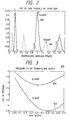
- FIG. 2 depicts graph 200 of probability density functions (pdfs) for magnitude squared 16- and 32-ary QAM signal constellations when the constellations, as shown in FIG. 1, are scaled to contain equal power.
- the pdf of the 16-ary constellation is shown in FIG. 2 using solid line 202 and the pdf of the 32-ary constellation is shown using dashed line 204.
- the pdfs are produced by first squaring the magnitude of a QAM signal having a 30 dB signal to noise ratio (SNR) and then accumulating the magnitude squared signal over a pre-determined period of time. Consequently, a peak (maximum) appears in graph 200 wherever a ring of symbols appeared in FIG. 1.
- the locations of the peaks are unique for each constellation size.
- the constellation size of a QAM signal can be uniquely determined.
- analyzing the QAM signal constellation in accordance with my inventive technique requires establishing a plurality of histogram bins.
- the specific number of bins depends on particular design parameters that are discussed in detail below.
- Each bin has a width defined by a range of normalized power that is centered at a normalized power level represented by each peak in graph 200.
- a counter associated with each of the histogram bins counts the number of symbols that occur within each bin over a pre-established time period. The count in each bin at the end of the period corresponds to the relative size of the pdf peaks and, therefore, uniquely defines the constellation size.
- Table 1 shows a correlation between the various amplitude peaks for each QAM signal, the location of these peaks measured in normalized power, and the expected amplitude value of each peak.
- QAM pdf peaks of normalized constellations 32 QAM PEAKS LOCATION AMPLITUDE 1 .1 1/8 2 .5 1/4 3 .9 1/8 4 1.3 1/4 5 1.7 1/4 16 QAM PEAKS 1 .2 1/4 2 1.0 1/2 3 1.8 1/4
- the expected number of symbols to be counted in each bin would be the total number of symbols (N) expected during a given time period multiplied by the expected pdf amplitude of the peak associated with a particular bin.
- N the total number of symbols
- Additive Guassian noise alters the pdf of the QAM signal by spreading and shifting the peaks.
- SNR signal-to-noise ratio
- the higher magnitude peaks e.g., peaks 4 and 5 in 32-ary QAM
- the lower magnitude peaks e.g., peaks 1, 2 and 3 in 32-ary QAM
- these lower magnitude peaks all occur below a normalized power of 1.0.
- the peaks above the normalized power of 1.0 are not examined by my inventive technique.
- a bin is located at a normalized power level of 0.5, e.g., peak 2 of the 32-ary QAM signal pdf
- a bin is located at a normalized power level of 1.0, e.g., approximately at peak 3 of the 32-ary QAM signal pdf and at peak 2 of the 16-ary QAM signal pdf.
- a 32-ary QAM signal constellation generates a higher count in bin 2 than in bin 3, i.e., the maximum value of the pdf at peak 2 is larger than at peak 3.
- the 16-ary QAM constellation generates a higher count in bin 3 than in bin 2. Consequently, the count in these two bins over a pre-established period uniquely defines the QAM signal constellation present.
- the error rate for such a determination method depends upon the width of the bins and the length of the period over which the count is taken. To optimize the bin widths and accumulation time, a statistical analysis of the interaction of these parameters is necessary.
- FIG. 3 depicts graph 300 of probability of error in detecting a symbol yersus bin width for both 16- and 32-ary QAM signals.
- the bins can be thought of as random variables each having a binomial distribution.
- the probability of a hit (symbol) falling within a given bin is computed by integrating the magnitude squared symbol plus noise pdf (FIG. 2) over the power range (width) of the bin.
- the number of symbols integrated is the number of trials in the binomial distribution.
- a random variable X is determined from the number of hits in each bin. Specifically, X is a difference between a number (N 2 ) of hits in bin 2 and a number (N 3 ) of hits in bin 3.
- N 2 and N 3 are independent variables, which, with respect to QAM modulated signals, is not strictly true.
- the pdf of X is a discrete convolution of two Poisson distributions representing N 2 and N 3 and, thus, can be numerically evaluated.
- the defining parameter for each of the Poisson distributions is an expected value of the number of hits in each bin.
- the value of this parameter is the probability of one hit in a bin (p) times the number of symbols examined (N).
- the probability of error for detecting a symbol correctly is determined by the bin width (which determines p) and the number of symbols accumulated (integrated).
- Each of these parameters can be graphed separately against the probability of error.
- FIG. 3 depicts graph 300 of the probability of error for both a 16- and a 32-ary QAM signals versus bin width for a fixed number of accumulated symbols.
- Curve 302 was formed using a 16-ary QAM signal having a 10 dB SNR and curve 304 was formed using a 32-ary QAM signal having a 13 dB SNR.
- the probabilities were calculated using a fixed accumulation (N) of 10,000 symbols.
- the graph shows the optimal bin width for minimizing the probability of error for both 16- and 32-ary QAM is between .25 and .3 of the normalized power.
- FIG. 4 depicts graph 400 of the probability of error for either a 16- or 32-ary QAM signal versus the integration time measured in number of symbols (N) for a fixed bin width.
- this graph shows that the probability of error decreases linearly as the integration time is lengthened.
- the integration time is selected for a maximum acceptable probability of error for a particular application of my technique.
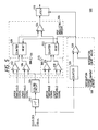
- FIG. 5 depicts a block diagram of circuit 500 which implements my inventive technique for determining the size of a QAM signal constellation.
- an input to this circuit is a digitized intermediate frequency (IF) signal produced by an analog-to-digital (A/D) converter within the receiver.
- Circuit 500 evaluates the digitized IF signal to determine the QAM signal constellation size from which the digitized IF signal was derived.
- circuit 500 contains squaring circuit 502, scaling circuit 504, pdf analyzing circuit 506, integration period establishment circuit 508 and latch 510.
- Squaring circuit 502 squares the magnitude of the QAM signal. Illustratively, such a squaring operation is accomplished by separating the in-phase (I) and quadrature-phase (Q) components of the QAM signal, squaring each independently, then summing the squared I and Q components to produce a magnitude squared signal. Squaring the magnitude of the QAM signal removes any variations of the symbol constellation caused by rotation of the constellation. Such rotation is typically caused by a lack of carrier lock by the receiver in which circuit 500 is used. Consequently, my inventive circuit does not require carrier lock prior to accomplishing the constellation size determination.
- the squaring circuit is connected to scaling circuit 504.
- the scaling circuit scales the digitized IF signal to within a range 0 to 2, i.e., the circuit normalizes the power of the digitized IF signal.
- scaling circuit 504 and squaring circuit 502 can be interchanged without detrimentally effecting the operation of my invention.
- scaling circuit 504 can be an automatic gain control circuit positioned after the IF signal A/D converter or elsewhere in the receiver.
- the scaling circuit is connected to pdf analyzing circuit 506.
- the pdf analyzing circuit establishes a number of bins in which symbols of the QAM signals are accumulated. By analyzing the accumulated symbols over a pre-defined period, the constellation size of the QAM signals can be uniquely determined.
- the pdf analyzing circuits contain two bins; one bin (bin 2) is centered at a scaled, normalized power level of .5, i.e., at peak 2 of the pdf of the 32-ary QAM signal (shown in FIG. 2) and another bin (bin 3) is centered at a scaled, normalized power level of 1.0, i.e., approximately at peak 3 of the pdf of the 32-ary QAM signal (shown in FIG. 2).
- the pdf analyzing circuit uses counters 520 and 522 to count a number of symbols that occur in each bin over a period of time established by integration period establishment circuit 508. During the period, the pdf analyzing circuit generates an output that represents which bin presently has a larger count. At the end of the integration period, the integration period establishment circuit resets the counters in the pdf analyzing circuit and, simultaneously, latches the output of that circuit.
- the latched signal represents the constellation size, i.e., whether the constellation is 16- or 32-ary.
- histogram bin circuit 506 contains comparators 512, 514, 516 and 518 for establishing histogram bins 511 and 513, counters 520 and 522 for counting the symbols in each bin and comparator 524 for determining which counter presently has the largest count.
- Comparators 512 and 514 form first histogram bin 511.
- the output signal of scaling circuit 504 connects to the positive input terminal of comparator 512 and to the negative input terminal of comparator 514.
- An upper threshold signal connects to the negative terminal of comparator 512 and a lower threshold signal connects to the positive input terminal of comparator 514.
- counter 520 is connected to the output of both comparators 512 and 514. The counter is incremented whenever the scaling circuit output signal is both larger than the lower threshold signal and smaller than the upper threshold signal.
- the comparators and their respective threshold levels define a window or bin width.
- the specific size of the bin width is optimally, as discussed above, .25 to .3 of normalized power.
- the bin width is set to a normalized power of .25.
- the first bin has a lower threshold signal level of .375 and an upper threshold signal level of .625 measured in normalized power.
- second bin 513 is established using comparators 516 and 518 in conjunction with upper and lower threshold signals. Using these threshold signals, the bin width of the second bin is also set to a normalized power of .25. Specifically, the lower threshold is .875 and the upper threshold is 1.125. Consequently, counter 522 is incremented whenever the soft decision signal is within this bin width.
- Each counter 520 and 522 has an output that indicates the present count of that counter.
- the output from counter 520 is connected to the positive input terminal of comparator 524; the output of counter 522 is connected to the negative input terminal of comparator 524.
- comparator 524 produces an output signal that indicates which counter has the presently larger count. For example, if counter 520 has a larger count than counter 522, the output of comparator 524 is a high level signal. In contrast, if the output of counter 522 is larger than the count of counter 520, the output of comparator 524 is a low level signal.
- Integration period establishment circuit 508 contains counter 526 and comparator 528.
- Counter 526 counts each and every symbol that is represented in the soft decision signal. A period duration is established by the integration count value.
- the integration count value is connected to the negative input of comparator 528.
- the output of counter 526 connects to the positive input of comparator 528.
- the integration count value is a relatively large number, e.g., 50,000.
- the output signal of comparator 528 is connected to the reset terminals of counters 520, 522 and 526 as well as to a latch terminal of latch 510.
- the latched signal Upon the occurrence of the rising edge of the output signal of comparator 528 changing states, all of the counters are reset to zero and the output signal of comparator 524 is latched. Once latched, the output signal of latch 510 is the level of the output signal of comparator 524 that was present at the end of the integration period. If counter 520 has a larger count than counter 522 at the end of the integration period, the latched signal will indicate that the soft decision signal was derived from a 32-ary QAM signal. Alternatively, if counter 522 has a larger count than counter 520 at the end of the integration period, the latched signal will indicate that the soft decision signal was derived from a 16-ary QAM signal. Consequently, the latched signal represents the QAM signal constellation size presently being received by the receiver in which circuit 500 is incorporated.
- circuit 500 achieves superb acquisition and error results. For example, when the bin width of both bins is set to .25 in normalized power and the integration time is set to 50,000 symbols, the circuit has a probability of error of 10 -8 for a 32-ary signal at 13 dB SNR. This error rate is equivalent to one error per two days of continuous operation of an HDTV receiver. Furthermore, the error rate for a 16-ary QAM signal is 10 -10 at 10 dB SNR. Using a 50,000 symbol integration period and a SNR of 10 dB, the circuit generally determines the constellation size within .01 seconds.
- the illustrative 16- and 32-ary constellation size detection apparatus (16/32 QAM apparatus) discussed above can be extended to determine the size of other QAM signal constellations.
- my inventive technique can be utilized to determine the size of one constellation out of M possible constellation sizes, where M is greater than 2.
- a particular design of an apparatus for determining constellation size directly depends upon the constellations to be discriminated amongst.
- the first step in designing such apparatus is to determine and graph the pdf of the magnitude squared of each of the expected QAM signals, e.g., as shown in FIG. 2 for 16- and 32-ary QAM signals. From such pdf graphs for the various expected QAM signals, the appropriate bin widths and bin positions that will facilitate optimum constellation size detection can be selected. For example, in the case of the 16/32 QAM apparatus discussed above, my technique utilized two histogram bins positioned near specific pdf peaks. In that particular case, where two constellation sizes are to be discriminated, my technique need only use two bins.
- a 2/64 QAM apparatus might use the same configuration as the previously described 16/32 QAM apparatus with the bin locations adjusted slightly to optimize performance for the constellations under consideration.
- M histogram bins are necessary to discriminate between M constellation sizes.
- Such apparatus uses three histogram bins. Two bins are identical to those in the 16/32 QAM apparatus and the third bin, i.e., two comparators and an associated counter, is positioned near the normalized power of 1.2. This is the location of a 64-ary QAM constellation point with a relatively high probability of occurrence, e.g., 3/16th. The ultimate decision as to which constellation size is present is based on the relative symbol accumulations in each of the three bins. The widths of the histogram bins and the integration time are adjusted to achieve the desired probability of error for the apparatus.
- the degrees of freedom can be met by using more than two histogram bins and analyzing absolute accumulation in each bin.
- several histogram bins are utilized to count symbols and the resulting count in each bin is matched against templates of expected count values corresponding to a pdf for each of the M expected QAM constellation sizes. The best match results in a constellation size being selected as the constellation size of the received QAM signal.
Landscapes
- Engineering & Computer Science (AREA)
- Computer Networks & Wireless Communication (AREA)
- Signal Processing (AREA)
- Digital Transmission Methods That Use Modulated Carrier Waves (AREA)
Description
- The invention relates to communications receivers, and particularly, the invention relates to apparatus for use in such a receiver for automatically detecting the constellation size of a received quadrature amplitude modulated (QAM) signal.
- Various communications systems utilize quadrature amplitude modulation (QAM) for transmission of relatively high data rate information within a limited transmission bandwidth. Typically, QAM communications systems use a fixed symbol constellation for all transmissions, e.g., sixteen positions or points within a constellation. Conventional QAM receivers are capable of receiving transmissions of only a single symbol constellation size.
- However, recently, sophisticated QAM communications systems are capable of transmitting variable symbol rate transmissions using two or more symbol constellations. For example, such a QAM system could vary its symbol rate between a 32-ary constellation and a 16-ary constellation depending upon the presence of atmospheric noise. Specifically, during periods of low atmospheric noise, such a QAM system can use 32-ary transmissions. When atmospheric noise, as measured at the transmitter, has increased above a pre-established noise threshold, the constellation size is then decreased to a 16-ary constellation. During periods of extremely low noise, the constellation size could be increased to transmissions of 32-ary, 64-ary or even 128-ary constellations. Alternatively, a QAM system may be required to transmit one constellation size over-the-air and a second constellation size over a cable broadcast system. As such, a "cable ready" receiver must be able to receive both constellation sizes.
- One such variable constellation size communication system is being considered by the Federal Communications Commission (FCC) as a standard transmission format for high definition television (HDTV). The particular standard would permit HDTV broadcasters to use either 16-ary or 32-ary QAM symbol constellations for broadcasting HDTV signals. As such, a given HDTV receiver may receive a 16-ary transmission when viewing one particular channel and a 32-ary transmission when viewing a second channel. Additionally, a given HDTV broadcaster may change its transmitted symbol constellation from 16- to 32-ary, or vice versa, whenever noise conditions permit the higher (lower) rate of transmission to a majority of the broadcast audience. Thus, an HDTV receiver must be capable of automatically determining whether a received broadcast is a 16- or 32-ary transmission. Such a determination must be accomplished whenever a user changes channels or the broadcaster changes transmission rates. Additionally, the constellation size determination must be accomplished relatively quickly such that a user will not notice the change in the constellation size of the broadcast, i.e., notice a loss of signal reception while the receiver adjusts to a new constellation size.
- Furthermore, HDTV cable broadcasts may utilize 64-ary transmissions. As such, a "cable ready" HDTV receiver must be capable of receiving 16, 32 and 64-ary transmissions.
- Typically, a receiver of variable constellation size transmissions contains demodulator circuits capable of demodulating each expected size of symbol constellation. In particular, a receiver capable of receiving both 16- and 32-ary symbol constellations would contain both a 16-ary demodulator and a 32-ary demodulator. In this manner, both symbol constellations are demodulated simultaneously even though only one constellation is transmitted. Thus, one demodulator produces no signal, while the other demodulator demodulates the received symbols and generates information therefrom. Though such a receiver accomplishes reception of either symbol constellation, such redundant demodulators are complex and costly to manufacture.
- Using an alternative technique to determine constellation size, an HDTV receiver contains a single demodulator having two modes of operation, i.e., one for each expected symbol constellation size. As such, the demodulator attempts to demodulate one of the constellation sizes, e.g., a 16-ary symbol constellation, using one of its two modes of operation. Meanwhile, circuitry within the receiver monitors an error rate from a Reed-Solomon decoder within the demodulator. If the error rate exceeds a pre-defined threshold, the receiver assumes that the demodulator is set to demodulate the incorrect symbol constellation size. In response, the receiver switches the demodulator to a second mode of operation, e.g., a 32-ary symbol constellation mode, capable of demodulating a second symbol constellation size, e.g., 32-ary. Simply stated, the error rate at the output of the Reed-Solomon decoder indicates which constellation is presently being demodulated. However, for a Reed-Solomon decoder to operate properly, a carrier recovery circuit must be locked onto a carrier for the transmission. Otherwise, the Reed-Solomon decoder produces a high error rate for both modes of operation. As such, this form of receiver first requires that a carrier lock be achieved before determining the constellation size. Detrimentally, this two-step process is relatively slow to determine the constellation size of the received broadcast. Consequently, a large amount of information can be lost while the receiver is achieving carrier lock and then determining the constellation size before beginning to demodulate the broadcast.
- In Proc. International Conference on Acoustics, Speech, and Signal Processing 1990, Vol. 3, pages 1651-1654, a technique is disclosed for identifying constellation size of a received quadrature amplitude modulated (QAM) signal using histogrammed magnitude analysis of a received QAM signal (the so-called "one-dimensional modulus" method). This method relies on first scaling the incoming received QAM symbols to a normalized power level. Thereafter, the scaled magnitude of the received symbols, which collectively forms a so-called modulus density function, is histogrammed, symbol by symbol, into 256 bins spanning a scaled symbol magnitude range of 0 to 2. To simplify the selection process, the counts that exist in just certain bin groupings are considered. These bin groupings are determined by the locations, in terms of bin count, of appropriate geometric characteristics that uniquely distinguish the size of the constellation, when mapped into a one-dimensional modulus projection such as specifically amplitude clusters and depressions. A decision is then made based on the count in the bin groupings as to whether the received constellation is of a certain size, e.g. 64-ary, or not.
- Symbols of a known QAM constellation are analyzed by the one-dimensional modulus method until a particular symbol error rate is reached. Thus, the factor that terminates symbol processing is a particular symbol error rate.
- In order to implement the one-dimensional modulus method in a QAM receiver, such as one for high definition television (HDTV) use, the receiver must contain circuitry that measures the error rate of the received symbols. This rate would then be used to appropriately terminate the observation interval at which point a decision as to constellation size would be made.
- In that regard, while a QAM receiver, such as an HDTV receiver, does provide some degree of error correction, through use of Trellis Code Modulation and a Reed-Solomon error correcting code, the resulting symbol error measurement available in such a receiver is too inaccurate, i.e. it is too coarse, to signify when a constellation has been identified. In such a QAM receiver, an accurate symbol error rate can only be determined after a constellation has been identified. Thus, the described approach, while attractive for academic study or computer simulation, is impractical for actual use within an HDTV QAM receiver.
- Therefore, a need exists in the art for apparatus, particularly though not exclusively for use in a HDTV QAM receiver, for automatically detecting the constellation size of a QAM transmission without requiring the QAM demodulator to, a priori, acquire carrier lock. Additionally, to minimize any noticeable signal impact to a viewer, this detection should be performed relatively quickly.
- My invention advantageously overcomes the disadvantages heretofore associated with receivers that require a priori carrier lock before determining constellation size of a received QAM signal. Specifically, through my invention the constellation size of a QAM signal, received by a QAM receiver, is directly determined without advantageously requiring carrier lock or redundant demodulators.
- In general, my invention determines the constellation size, e.g., 4, 16, 32-ary, of a particular received QAM signal by analyzing the probability density function (pdf) of that signal. To properly analyze this signal, its magnitude is first squared and then normalized to a preset value, e.g., 2.0. As such, the signal power in any of the various constellations is normalized to a fixed level. In addition, squaring the magnitude of the QAM signal removes the requirement to achieve carrier lock prior to attempting to determine the constellation size. Then, through generating a histogram of the squared and normalized QAM signal, the number of levels of modulation contained in the QAM signal is determined. Each constellation size has a unique number of modulation levels and thus a unique histogram. For example, a 4-ary constellation contains one modulation level, 16-ary contains three modulation levels and 32-ary contains five modulation levels. Each modulation level produces a histogram. Thus, by generating a histogram, my invention determines the constellation size of a QAM signal without requiring a priori carrier lock before accomplishing such a determination.
- Specifically, in accordance with my inventive teachings, a number of histogram bins is established for each different QAM constellation in a QAM signal that is expected to be received. Each bin has a pre-defined width and is located at an expected peak in a pdf of a corresponding one of the QAM signals. The peaks are located at various normalized power levels of the expected QAM signal; the bin widths are defined by a range of power levels around each peak location. The number of bins and their specific locations depend upon the number of different constellation sizes and the size of those constellations that are expected to be received. In operation, a counter associated with each bin counts (accumulates) the number of symbols that fall therein. The symbols are counted over a fixed time period. At the end of the period, my technique compares, to one another, the number of symbols counted by each counter. The result of the comparison indicates the number of modulation levels for the QAM signal being received which, in turn, indicates the constellation size of that QAM signal.
- The teachings of the present invention can be readily understood by considering the following detailed description in conjunction with the accompanying drawings, in which:
- FIG. 1 graphically shows 16- and 32-ary quadrature amplitude modulation (QAM) signal constellations having equal power levels;
- FIG. 2 depicts a graph of the probability density functions (pdfs) of magnitude squared 16- and 32-ary QAM signals;
- FIG. 3 depicts a graph of the probability of error versus bin width for both 16- and 32-ary QAM signals;
- FIG. 4 depicts a graph of the probability of error versus integration length for either 16- or 32-ary QAM signals; and
- FIG. 5 depicts a block diagram of my inventive modulation
level detector circuit 500. - To facilitate understanding, identical reference numerals have been used, where possible, to designate identical elements that are common to the figures.
- After considering the following description, those skilled in the art will clearly realize that the teachings of my invention can be readily utilized in various communications receivers that receive quadrature amplitude modulated (QAM) signals of various constellation sizes. In particular, my invention is used to determine the constellation size of a QAM signal without requiring carrier lock prior to making such a determination.
- In general, my inventive apparatus first generates a square of the magnitude of a received QAM signal, i.e., a magnitude squared QAM signal. The magnitude squared QAM signal is then accumulated over a pre-defined time period to produce a probability density function (pdf) for the QAM signal. Each QAM signal constellation size has a unique pdf, e.g., a 32-ary QAM signal produces a pdf having five peaks (maximums), a 16-ary QAM signal produces a pdf having three peaks. Each peak corresponds to a concentric ring of symbol amplitudes, i.e., a modulation level, within the constellation. The resulting pdf of the received QAM signal is monitored, with the constellation size being determined therefrom. The constellation size determination is then passed to a demodulator which in turn, takes whatever action is necessary to demodulate a QAM signal having that particular constellation size.
- The following detailed discussion of my invention illustratively focuses upon using my invention to determine whether a QAM signal has a 16- or 32-ary constellation. However, those skilled in the art will realize that the invention can be used to determine whether a QAM signal is any one of a plurality of M-ary constellation sizes.
- FIG. 1 depicts graph 100 of a 16-ary QAM signal constellation (each symbol is shown as an X) superimposed over a 32-ary QAM signal constellation (each symbol is shown as an O), where each constellation contains equal power. In other words, the constellations have been equalized to have equivalent power content. For each constellation, each symbol within that constellation falls upon one of a number of pre-defined concentric rings that represent symbol magnitude. Specifically, the 16-ary constellation has each of its symbols fall on
rings 102, 104 and 106 (all shown as dashed lines). In contrast, the 32-ary constellation has the magnitude of its symbols aligned withrings - FIG. 2 depicts graph 200 of probability density functions (pdfs) for magnitude squared 16- and 32-ary QAM signal constellations when the constellations, as shown in FIG. 1, are scaled to contain equal power. The pdf of the 16-ary constellation is shown in FIG. 2 using
solid line 202 and the pdf of the 32-ary constellation is shown using dashedline 204. The pdfs are produced by first squaring the magnitude of a QAM signal having a 30 dB signal to noise ratio (SNR) and then accumulating the magnitude squared signal over a pre-determined period of time. Consequently, a peak (maximum) appears in graph 200 wherever a ring of symbols appeared in FIG. 1. The locations of the peaks are unique for each constellation size. Thus, by analyzing the pdfs to determine the locations of peaks therein, the constellation size of a QAM signal can be uniquely determined. - In general, analyzing the QAM signal constellation in accordance with my inventive technique requires establishing a plurality of histogram bins. The specific number of bins depends on particular design parameters that are discussed in detail below. Each bin has a width defined by a range of normalized power that is centered at a normalized power level represented by each peak in graph 200. A counter associated with each of the histogram bins counts the number of symbols that occur within each bin over a pre-established time period. The count in each bin at the end of the period corresponds to the relative size of the pdf peaks and, therefore, uniquely defines the constellation size.
- Table 1 shows a correlation between the various amplitude peaks for each QAM signal, the location of these peaks measured in normalized power, and the expected amplitude value of each peak.
TABLE 1: QAM pdf peaks of normalized constellations 32 QAM PEAKS LOCATION AMPLITUDE 1 .1 1/8 2 .5 1/4 3 .9 1/8 4 1.3 1/4 5 1.7 1/4 16 QAM PEAKS 1 .2 1/4 2 1.0 1/2 3 1.8 1/4 - If a large number of symbols is histogrammed into bins surrounding each of the pdf peaks, the expected number of symbols to be counted in each bin would be the total number of symbols (N) expected during a given time period multiplied by the expected pdf amplitude of the peak associated with a particular bin. However, in the presence of noise, the histogram is degraded. Additive Guassian noise alters the pdf of the QAM signal by spreading and shifting the peaks. For relatively high signal-to-noise ratios (SNR), the pdf peaks will stand out above the noise, but at low SNR, the peaks smear together and become indistinguishable from one another. Typically, the higher magnitude peaks, e.g., peaks 4 and 5 in 32-ary QAM, are most severely affected by additive noise and become indistinguishable before the lower magnitude peaks, e.g., peaks 1, 2 and 3 in 32-ary QAM, become indistinguishable. These lower magnitude peaks all occur below a normalized power of 1.0. To optimize performance when selecting between 16- or 32-ary constellations, the peaks above the normalized power of 1.0 are not examined by my inventive technique.
- Additionally, for the illustrative use of my technique to differentiate 16- from 32-ary QAM, counting the number of symbols that occur in each bin would require eight bins and a rather significant amount of circuitry to compare the counts of each counter associated with each bin to determine the constellation size. The circuitry required to differentiate between 16- and 32-ary QAM signals can be significantly reduced by using only two bins. Specifically, a bin (bin 2) is located at a normalized power level of 0.5, e.g.,
peak 2 of the 32-ary QAM signal pdf, and a bin (bin 3) is located at a normalized power level of 1.0, e.g., approximately atpeak 3 of the 32-ary QAM signal pdf and atpeak 2 of the 16-ary QAM signal pdf. As such, over a give time period, a 32-ary QAM signal constellation generates a higher count inbin 2 than inbin 3, i.e., the maximum value of the pdf atpeak 2 is larger than atpeak 3. In contrast, the 16-ary QAM constellation generates a higher count inbin 3 than inbin 2. Consequently, the count in these two bins over a pre-established period uniquely defines the QAM signal constellation present. The error rate for such a determination method depends upon the width of the bins and the length of the period over which the count is taken. To optimize the bin widths and accumulation time, a statistical analysis of the interaction of these parameters is necessary. - FIG. 3 depicts
graph 300 of probability of error in detecting a symbol yersus bin width for both 16- and 32-ary QAM signals. To derivegraph 300, the bins can be thought of as random variables each having a binomial distribution. The probability of a hit (symbol) falling within a given bin is computed by integrating the magnitude squared symbol plus noise pdf (FIG. 2) over the power range (width) of the bin. The number of symbols integrated is the number of trials in the binomial distribution. From the number of hits in each bin, a random variable X is determined. Specifically, X is a difference between a number (N2) of hits inbin 2 and a number (N3) of hits inbin 3. Consequently, the overall probability of error for my technique is represented by equation (1), as follows:
X is a difference between a number (N2) of hits inbin 2 and a number (N3) of hits inbin 3. - To evaluate the probability density of X, certain assumptions and approximations must be made about N2 and N3. Since the number of symbols examined is assumed to be very large, e.g., 10,000 or more, and the probability of a hit in a given bin is relatively small, then N2 and N3 can each be approximated by a Poisson distribution. Also, for numerical simplicity, it is assumed that N2 and N3 are independent variables, which, with respect to QAM modulated signals, is not strictly true. However, when the number of symbols is relatively large and the SNR is relatively high, the accumulation in each bin has little effect upon the accumulation in another bin. Under these assumptions and approximations, the pdf of X is a discrete convolution of two Poisson distributions representing N2 and N3 and, thus, can be numerically evaluated.
- The defining parameter for each of the Poisson distributions is an expected value of the number of hits in each bin. The value of this parameter is the probability of one hit in a bin (p) times the number of symbols examined (N). Thus, the probability of error for detecting a symbol correctly is determined by the bin width (which determines p) and the number of symbols accumulated (integrated). Each of these parameters can be graphed separately against the probability of error.
- In particular, FIG. 3 depicts
graph 300 of the probability of error for both a 16- and a 32-ary QAM signals versus bin width for a fixed number of accumulated symbols.Curve 302 was formed using a 16-ary QAM signal having a 10 dB SNR andcurve 304 was formed using a 32-ary QAM signal having a 13 dB SNR. The probabilities were calculated using a fixed accumulation (N) of 10,000 symbols. The graph shows the optimal bin width for minimizing the probability of error for both 16- and 32-ary QAM is between .25 and .3 of the normalized power. - FIG. 4 depicts
graph 400 of the probability of error for either a 16- or 32-ary QAM signal versus the integration time measured in number of symbols (N) for a fixed bin width. As would be expected, this graph shows that the probability of error decreases linearly as the integration time is lengthened. However, in practice, it is desirable to minimize the integration time, i.e., minimize the signal acquisition time of the receiver in which my technique is used. Therefore, the integration time is selected for a maximum acceptable probability of error for a particular application of my technique. - FIG. 5 depicts a block diagram of
circuit 500 which implements my inventive technique for determining the size of a QAM signal constellation. In general, an input to this circuit is a digitized intermediate frequency (IF) signal produced by an analog-to-digital (A/D) converter within the receiver.Circuit 500 evaluates the digitized IF signal to determine the QAM signal constellation size from which the digitized IF signal was derived. - Specifically,
circuit 500 contains squaringcircuit 502, scalingcircuit 504,pdf analyzing circuit 506, integrationperiod establishment circuit 508 andlatch 510. Squaringcircuit 502 squares the magnitude of the QAM signal. Illustratively, such a squaring operation is accomplished by separating the in-phase (I) and quadrature-phase (Q) components of the QAM signal, squaring each independently, then summing the squared I and Q components to produce a magnitude squared signal. Squaring the magnitude of the QAM signal removes any variations of the symbol constellation caused by rotation of the constellation. Such rotation is typically caused by a lack of carrier lock by the receiver in whichcircuit 500 is used. Consequently, my inventive circuit does not require carrier lock prior to accomplishing the constellation size determination. - The squaring circuit is connected to scaling
circuit 504. The scaling circuit scales the digitized IF signal to within arange 0 to 2, i.e., the circuit normalizes the power of the digitized IF signal. Those skilled in the art will recognize that scalingcircuit 504 and squaringcircuit 502 can be interchanged without detrimentally effecting the operation of my invention. In fact, scalingcircuit 504 can be an automatic gain control circuit positioned after the IF signal A/D converter or elsewhere in the receiver. - The scaling circuit is connected to
pdf analyzing circuit 506. In general, the pdf analyzing circuit establishes a number of bins in which symbols of the QAM signals are accumulated. By analyzing the accumulated symbols over a pre-defined period, the constellation size of the QAM signals can be uniquely determined. Specifically, the pdf analyzing circuits contain two bins; one bin (bin 2) is centered at a scaled, normalized power level of .5, i.e., atpeak 2 of the pdf of the 32-ary QAM signal (shown in FIG. 2) and another bin (bin 3) is centered at a scaled, normalized power level of 1.0, i.e., approximately atpeak 3 of the pdf of the 32-ary QAM signal (shown in FIG. 2). Usingcounters period establishment circuit 508. During the period, the pdf analyzing circuit generates an output that represents which bin presently has a larger count. At the end of the integration period, the integration period establishment circuit resets the counters in the pdf analyzing circuit and, simultaneously, latches the output of that circuit. The latched signal represents the constellation size, i.e., whether the constellation is 16- or 32-ary. - More specifically,
histogram bin circuit 506 containscomparators histogram bins comparator 524 for determining which counter presently has the largest count. -
Comparators first histogram bin 511. The output signal of scalingcircuit 504 connects to the positive input terminal ofcomparator 512 and to the negative input terminal ofcomparator 514. An upper threshold signal connects to the negative terminal ofcomparator 512 and a lower threshold signal connects to the positive input terminal ofcomparator 514. Additionally,counter 520 is connected to the output of bothcomparators - Similarly,
second bin 513 is established usingcomparators counter 522 is incremented whenever the soft decision signal is within this bin width. - Each
counter counter 520 is connected to the positive input terminal ofcomparator 524; the output ofcounter 522 is connected to the negative input terminal ofcomparator 524. As such,comparator 524 produces an output signal that indicates which counter has the presently larger count. For example, ifcounter 520 has a larger count thancounter 522, the output ofcomparator 524 is a high level signal. In contrast, if the output ofcounter 522 is larger than the count ofcounter 520, the output ofcomparator 524 is a low level signal. - Integration
period establishment circuit 508 contains counter 526 andcomparator 528. Counter 526 counts each and every symbol that is represented in the soft decision signal. A period duration is established by the integration count value. The integration count value is connected to the negative input ofcomparator 528. The output ofcounter 526 connects to the positive input ofcomparator 528. Typically, the integration count value is a relatively large number, e.g., 50,000. When the output ofcounter 526 exceeds the period count value, the output of the comparator changes states. The output signal ofcomparator 528 is connected to the reset terminals ofcounters latch 510. Upon the occurrence of the rising edge of the output signal ofcomparator 528 changing states, all of the counters are reset to zero and the output signal ofcomparator 524 is latched. Once latched, the output signal oflatch 510 is the level of the output signal ofcomparator 524 that was present at the end of the integration period. Ifcounter 520 has a larger count than counter 522 at the end of the integration period, the latched signal will indicate that the soft decision signal was derived from a 32-ary QAM signal. Alternatively, ifcounter 522 has a larger count than counter 520 at the end of the integration period, the latched signal will indicate that the soft decision signal was derived from a 16-ary QAM signal. Consequently, the latched signal represents the QAM signal constellation size presently being received by the receiver in whichcircuit 500 is incorporated. - In operation,
circuit 500 achieves superb acquisition and error results. For example, when the bin width of both bins is set to .25 in normalized power and the integration time is set to 50,000 symbols, the circuit has a probability of error of 10-8 for a 32-ary signal at 13 dB SNR. This error rate is equivalent to one error per two days of continuous operation of an HDTV receiver. Furthermore, the error rate for a 16-ary QAM signal is 10-10 at 10 dB SNR. Using a 50,000 symbol integration period and a SNR of 10 dB, the circuit generally determines the constellation size within .01 seconds. - The illustrative 16- and 32-ary constellation size detection apparatus (16/32 QAM apparatus) discussed above can be extended to determine the size of other QAM signal constellations. In fact, as broadly described below, my inventive technique can be utilized to determine the size of one constellation out of M possible constellation sizes, where M is greater than 2.
- In general, a particular design of an apparatus for determining constellation size directly depends upon the constellations to be discriminated amongst. However, no matter how many or what size constellations are expected as received QAM signals, the first step in designing such apparatus is to determine and graph the pdf of the magnitude squared of each of the expected QAM signals, e.g., as shown in FIG. 2 for 16- and 32-ary QAM signals. From such pdf graphs for the various expected QAM signals, the appropriate bin widths and bin positions that will facilitate optimum constellation size detection can be selected. For example, in the case of the 16/32 QAM apparatus discussed above, my technique utilized two histogram bins positioned near specific pdf peaks. In that particular case, where two constellation sizes are to be discriminated, my technique need only use two bins. Consequently, a 2/64 QAM apparatus might use the same configuration as the previously described 16/32 QAM apparatus with the bin locations adjusted slightly to optimize performance for the constellations under consideration. However, in general, for expanded use of my technique, M histogram bins are necessary to discriminate between M constellation sizes.
- Considering apparatus which discriminates between constellation sizes of 16, 32 and 64-ary QAM signals, such apparatus uses three histogram bins. Two bins are identical to those in the 16/32 QAM apparatus and the third bin, i.e., two comparators and an associated counter, is positioned near the normalized power of 1.2. This is the location of a 64-ary QAM constellation point with a relatively high probability of occurrence, e.g., 3/16th. The ultimate decision as to which constellation size is present is based on the relative symbol accumulations in each of the three bins. The widths of the histogram bins and the integration time are adjusted to achieve the desired probability of error for the apparatus.
- On the other hand, when one of M constellation sizes is to be detected where M is greater than three, a more sophisticated apparatus than that of the 16/32 QAM apparatus is typically needed. As a general rule, if the apparatus must discriminate between M constellation sizes, the apparatus must be capable of measuring at least M-1 degrees of freedom within the QAM signal. This is accomplished by using the absolute accumulations (symbol counts) in each of the histogram bins rather than the relative accumulations as accomplished by the 16/32 QAM apparatus. As such, the absolute accumulations in each bin are compared to expected accumulation values that should result at the end of the integration period. This absolute accumulation to expected accumulation comparison is accomplished in conjunction with the relative accumulation comparison as discussed previously. As such, the appropriate number of degrees of freedom can be met without using an excessive number of bins.
- Alternatively, the degrees of freedom can be met by using more than two histogram bins and analyzing absolute accumulation in each bin. At the expense of more implementation hardware, several histogram bins are utilized to count symbols and the resulting count in each bin is matched against templates of expected count values corresponding to a pdf for each of the M expected QAM constellation sizes. The best match results in a constellation size being selected as the constellation size of the received QAM signal.
Claims (16)
- Apparatus for determining the constellation size of a quadrature amplitude modulated signal, hereinafter referred to as QAM signal, wherein said QAM signal contains one of a plurality of constellation sizes, comprising:means for squaring (502) a magnitude of said QAM signal and for producing a magnitude squared QAM signal;means, connected to said squaring means, for analyzing (506) a probability density function of said QAM signal by examining the magnitude squared QAM signal to determine the constellation size of the QAM signal being received;means, connected to said analyzing means, for establishing (508) a duration during which said analyzing means analyzes said QAM signal;means, connected to said analyzing means and said duration establishing means, for producing (510) a signal indicative of the constellation size of said QAM signal being received;characterized in thatsaid analyzing means comprises means for accumulating symbols (511, 513, 520, 522) of said magnitude squared QAM signal during said duration; the accumulating means further comprisinga plurality of bins (511, 513) each having a position and width such that each bin is positioned to accumulate symbols occurring near at least one peak in said probability density function; anda plurality of counters (520, 522), each one connected to a bin, that are incremented whenever said magnitude squared QAM signal exceeds a lower threshold signal and does not exceed an upper threshold signal, whereby a difference in magnitudes between said upper and lower threshold signals establishes said bin width, and whereby said accumulating means produces a count of said symbols that occur within the bin width of said plurality of bins; andmeans, connected to each of said counters, for comparing (524), to one another, said counts accumulated by each counter during said established duration and wherein said producing means, in response to said count comparison, produces the signal indicative of the constella- tion size of said QAM signal being received.
- The apparatus of claim 1, wherein said bin width for each of said bins is established by first and second comparators (512, 514, 516, 518), wherein said magnitude squared QAM signal forms an input to a positive terminal of said first comparator and an upper threshold signal forms an input to a negative terminal of said first comparator, and wherein said magnitude squared QAM signal forms an input to a negative terminal of said second comparator and a lower threshold signal forms an input to a positive terminal of said second comparator.
- Apparatus for determining the constellation size of a quadrature amplitude modulated signal, hereinafter referred to as QAM signal, wherein said QAM signal contains one of a plurality of constellation sizes, comprising:means for squaring (502) a magnitude of said QAM signal and for producing a magnitude squared QAM signal;means, connected to said squaring means, for analyzing (506) a probability density function of said QAM signal by examining the magnitude squared QAM signal to determine the constellation size of the QAM signal being received;means, connected to said analyzing means, for establishing (508) a duration during which said analyzing means analyzes said QAM signal;means, connected to said analyzing means and said duration establishing means, for producing (510) a signal indicative of the constellation size of said QAM signal being received;
characterized in thatsaid analyzing means comprises means for accumulating symbols (511, 513, 520, 522) of said magnitude squared QAM signal during said duration; the accumulating means further comprising a plurality of bins (511, 513) each having a position and width such that each bin is positioned to accumulate symbols occurring near at least one peak in said probability density function; anda plurality of counters (520,522), each one connected to a bin, that are incremented whenever said magnitude squared QAM signal exceeds a lower threshold signal and does not exceed an upper threshold signal, whereby a difference in magnitudes between said upper and lower threshold signals establishes said bin width and whereby said accumulating means produces a count of said symbols that occur within the bin width of said plurality of bins; andmeans, connected to each of said counters, for comparing said count accumulated by each counter during said established duration to an expected count value for each of said bins and wherein said producing means, in response to said count comparison, produces the signal indicative of the constellation size of said QAM signal being received. - The apparatus of claim 3, wherein said comparing means further comprises means (524), connected to each of said counters, for comparing, to one another, said counts accumulated by each counter during said established duration.
- The apparatus of claim 3 or 4, wherein said QAM signal is either a 16-ary or 32-ary QAM signal and wherein said accumulating means contains two bins (511, 513) having a counter (520, 522) connected to each bin.
- The apparatus of claim 5, wherein said comparing means determines which of the two counters counts to the largest count during the established duration, and wherein said producing means produces a signal indicative of which counter has the largest count.
- The apparatus of claim 3, wherein said QAM signal is either a 16-ary, 32-ary or 64-ary QAM signal and wherein said accumulating means contains three bins having a counter connected to each bin.
- The apparatus of claim 7, wherein said comparing means determines which of the three counters counts to the largest count during the established duration, and wherein said producing means produces a signal indicative of which counter has the largest count.
- Method for determining the constellation size of a quadrature amplitude modulated signal, hereinafter referred to as QAM signal, wherein said QAM signal contains one of a plurality of constellation sizes, comprising the steps of:receiving a QAM signal having a constellation size;squaring a magnitude of said QAM signal to produce a magnitude squared QAM signal;analyzing a probability density function of said QAM signal by examining the magnitude squared QAM signal to determine the constellation size of the QAM signal being received;establishing a duration during which said analyzing step is accomplished;producing a signal indicative of the constellation size of the QAM signal being received; characterised in that said analyzing step further comprises the steps of establishing a plurality of bins each having a position and width and positioning each of said bins to accumulate symbols occurring near at least one peak in said probability density function. whereby a difference in magnitudes of an upper and a lower threshold signal establishes the bin width.accumulating symbols of said magnitude squared QAM signal during said established duration;counting a number of symbols of said magnitude squared QAM signal that occur within said plurality of bins during the established duration;comparing to one another the number of symbols counted in each bin during the established duration and producing, in response to said count comparison, the signal indicative of the constellation size of the QAM signal being received.
- The method of claim 9, wherein said accumulating step further comprises the step of establishing each of said bins by comparing said magnitude squared QAM signal to upper and lower threshold signals.
- Method for determining the constellation size of a quadrature amplitude modulated signal, hereinafter referred to as QAM signal, wherein said QAM signal contains one of a plurality of constellation sizes, comprising the steps of:receiving a QAM signal having a constellation size;squaring a magnitude of said QAM signal to produce a magnitude squared QAM signal;analyzing a probability density function of said QAM signal by examining the magnitude squared QAM signal to determine the constellation size of the QAM signal being received;establishing a duration during which said analyzing step is accomplished;producing a signal indicative of the constellation size of the QAM signal being received; characterised in that said analyzing step further comprises the steps ofestablishing a plurality of bins each having a position and width and positioning each of said bins to accumulate symbols occurring near at least one peak in said probability density function. whereby a difference in magnitudes of an upper and a lower threshold signals establishes the bin width.accumulating symbols of said magnitude squared QAM signal during said established duration;counting a number of symbols of said magnitude squared QAM signal that occur within said plurality of bins during the established duration;comparing the number of symbols counted in each bin during the established duration to an expected count value for each of said bins and producing, in response to said count comparison, the signal indicative of the constellation size of the QAM signal being received.
- The method of claim 11, wherein said comparing step further comprises the step of comparing, to one another, the number of symbols counted in each bin during the established period.
- The method of claim 11 or 12, wherein said QAM signal is either a 16-ary or 32-ary QAM signal and wherein said accumulating step establishes two bins.
- The method of claim 13, wherein said comparing step further comprises the steps of counting, during the established duration, the number of symbols that occur in each of the two bins, determining which bin had the largest number of symbols occur therein, and producing, in response to the bin with the largest number of symbols, a signal indicative of which type of QAM signal is being received.
- The method of claim 11, wherein said QAM signal is either a 16-ary, 32-ary QAM signal and wherein said accumulating step establishes three bins.
- The method of claim 15, wherein said comparing step further comprises the steps of counting, during the established duration, the number of symbols that occur in each of the three bins, determining which bin had the largest number of symbols, a signal indicative of which type of QAM signal is being received.
Applications Claiming Priority (2)
| Application Number | Priority Date | Filing Date | Title |
|---|---|---|---|
| US109651 | 1987-10-16 | ||
| US08/109,651 US5381450A (en) | 1993-08-20 | 1993-08-20 | Technique for automatically detecting the constellation size of a quadrature amplitude modulated (QAM) signal |
Publications (2)
| Publication Number | Publication Date |
|---|---|
| EP0639915A1 EP0639915A1 (en) | 1995-02-22 |
| EP0639915B1 true EP0639915B1 (en) | 1997-12-29 |
Family
ID=22328829
Family Applications (1)
| Application Number | Title | Priority Date | Filing Date |
|---|---|---|---|
| EP94112502A Expired - Lifetime EP0639915B1 (en) | 1993-08-20 | 1994-08-10 | Technique and apparatus for automatically detecting the constellation size of a quadrature amplitude modulated (QAM) signal |
Country Status (4)
| Country | Link |
|---|---|
| US (1) | US5381450A (en) |
| EP (1) | EP0639915B1 (en) |
| JP (1) | JPH07170307A (en) |
| DE (1) | DE69407512T2 (en) |
Cited By (1)
| Publication number | Priority date | Publication date | Assignee | Title |
|---|---|---|---|---|
| DE102007003105A1 (en) | 2007-01-16 | 2008-07-17 | Micronas Gmbh | Quadrature amplitude-modulated signals combination determining device, has converter to convert signals into coordinates that initializes radius as signals radial part, and recognization unit to determine signals combination from radius |
Families Citing this family (36)
| Publication number | Priority date | Publication date | Assignee | Title |
|---|---|---|---|---|
| US5687163A (en) * | 1995-06-07 | 1997-11-11 | Cirrus Logic, Inc. | Method and apparatus for signal classification using I/Q quadrant histogram |
| DE19620843B4 (en) * | 1996-05-23 | 2005-08-11 | Siemens Ag | Modulation carrier modulation method and mobile communication system |
| JP3442262B2 (en) * | 1996-06-07 | 2003-09-02 | シャープ株式会社 | AGC system responding to baseband signal distortion |
| US6278743B1 (en) * | 1996-11-12 | 2001-08-21 | Zenith Electronics Corporation | Non linear amplitude precorrection for HDTV transmitter |
| US6108375A (en) * | 1997-07-15 | 2000-08-22 | Lucent Technologies Inc. | Equalization circuit for unknown QAM constellation size |
| DE19740739A1 (en) | 1997-09-16 | 1999-03-18 | Siemens Ag | Automatic detection method by QAM-receiver for QAM-mode transmitted signal |
| JP3741858B2 (en) * | 1998-03-19 | 2006-02-01 | 富士通株式会社 | Adaptive modulation system |
| US7076003B1 (en) * | 1999-03-03 | 2006-07-11 | Agere Systems Inc. | Constellation design for modem receiver |
| US6133785A (en) * | 1999-06-30 | 2000-10-17 | Harris Corporation | False carrier lock receiver and associated methods for detection |
| US20010055348A1 (en) * | 2000-03-31 | 2001-12-27 | Anderson Christopher L. | Sequential quadrant demodulation of digitally modulated radio signals |
| JP2002152182A (en) * | 2000-11-10 | 2002-05-24 | Taiyo Musen Co Ltd | Data transmission system of radio buoy |
| US7349486B2 (en) * | 2001-07-19 | 2008-03-25 | Agere Systems Guardian Corporation | System and method for recognizing zero-amplitude symbols in a QAM signal and digital receiver incorporating the same |
| KR100441196B1 (en) * | 2002-01-14 | 2004-07-21 | 기가텔레콤 (주) | Apparatus for continuous phase quadrature amplitude modulation and demodulation |
| US6711528B2 (en) * | 2002-04-22 | 2004-03-23 | Harris Corporation | Blind source separation utilizing a spatial fourth order cumulant matrix pencil |
| US6993440B2 (en) * | 2002-04-22 | 2006-01-31 | Harris Corporation | System and method for waveform classification and characterization using multidimensional higher-order statistics |
| JP3738997B2 (en) * | 2002-12-05 | 2006-01-25 | 株式会社日立国際電気 | Communication method |
| US7187326B2 (en) * | 2003-03-28 | 2007-03-06 | Harris Corporation | System and method for cumulant-based geolocation of cooperative and non-cooperative RF transmitters |
| DE10344756A1 (en) * | 2003-09-25 | 2005-05-12 | Micronas Gmbh | Method and circuit arrangement for deciding a symbol in the complex phase space of a quadrature modulation method |
| US7269205B2 (en) | 2003-09-26 | 2007-09-11 | Telefonaktiebolaget Lm Ericsson (Publ) | Method and apparatus for signal demodulation |
| US20100265139A1 (en) * | 2003-11-18 | 2010-10-21 | Harris Corporation | System and method for cumulant-based geolocation of cooperative and non-cooperative RF transmitters |
| CN100379233C (en) * | 2004-09-03 | 2008-04-02 | 杭州国芯科技有限公司 | Method for improving timing locking test |
| US7379507B2 (en) * | 2004-10-01 | 2008-05-27 | Industrial Technology Research Institute | Method and device for modulation recognition of digitally modulated signals with multi-level magnitudes |
| US7609754B2 (en) | 2005-08-30 | 2009-10-27 | Telefonaktiebolaget Lm Ericsson (Publ) | Method and apparatus for received communication signal processing |
| US7590167B2 (en) | 2005-08-30 | 2009-09-15 | Telefonaktiebolaget Lm Ericsson (Publ) | Method and apparatus for QAM demodulation in a generalized rake receiver |
| EP1918909B1 (en) * | 2006-11-03 | 2010-07-07 | Psytechnics Ltd | Sampling error compensation |
| US7962670B2 (en) * | 2007-06-06 | 2011-06-14 | Lantiq Deutschland Gmbh | Pin multiplexing |
| US20090097401A1 (en) * | 2007-10-12 | 2009-04-16 | Wael William Diab | Method and system for configurable data rate thresholds for energy efficient ethernet |
| US7864794B2 (en) * | 2007-10-12 | 2011-01-04 | Broadcom Corporation | Method and system for managing an energy efficient network utilizing audio video bridging |
| US8588254B2 (en) * | 2007-12-17 | 2013-11-19 | Broadcom Corporation | Method and system for energy efficient signaling for 100mbps Ethernet using a subset technique |
| US8194548B2 (en) * | 2007-12-17 | 2012-06-05 | Broadcom Corporation | Method and system for duty cycling portions of a network device based on aggregate throughput of the device |
| US8724464B2 (en) * | 2007-12-17 | 2014-05-13 | Broadcom Corporation | Method and system for near continuous data rate limit adjustment via a plurality of link variables in an energy efficient network |
| JP5628153B2 (en) * | 2008-06-03 | 2014-11-19 | トムソン ライセンシングThomson Licensing | Apparatus and method for determining signal format |
| US8223890B1 (en) | 2009-10-30 | 2012-07-17 | The United States Of America As Represented By The Secretary Of The Army | Asymptotically optimal modulation classification method for software defined radios |
| US8817431B2 (en) * | 2009-12-18 | 2014-08-26 | True-Safe Technologies, Inc. | System and integrated method for a parallel and series arc fault circuit interrupter |
| CN106780415B (en) | 2016-12-30 | 2020-03-10 | 华为技术有限公司 | A kind of histogram statistics circuit and multimedia processing system |
| US20190136820A1 (en) * | 2017-11-07 | 2019-05-09 | Semiconductor Components Industries, Llc | Methods and apparatus for an ignition system |
Family Cites Families (2)
| Publication number | Priority date | Publication date | Assignee | Title |
|---|---|---|---|---|
| GB8606572D0 (en) * | 1986-03-17 | 1986-04-23 | Hewlett Packard Ltd | Analysis of digital radio transmissions |
| JPH04183177A (en) * | 1990-11-19 | 1992-06-30 | Matsushita Electric Ind Co Ltd | Cumulative histogram circuit, interpolation circuit, and image quality correction circuit |
-
1993
- 1993-08-20 US US08/109,651 patent/US5381450A/en not_active Expired - Fee Related
-
1994
- 1994-08-10 DE DE69407512T patent/DE69407512T2/en not_active Expired - Fee Related
- 1994-08-10 EP EP94112502A patent/EP0639915B1/en not_active Expired - Lifetime
- 1994-08-19 JP JP6195801A patent/JPH07170307A/en active Pending
Cited By (4)
| Publication number | Priority date | Publication date | Assignee | Title |
|---|---|---|---|---|
| DE102007003105A1 (en) | 2007-01-16 | 2008-07-17 | Micronas Gmbh | Quadrature amplitude-modulated signals combination determining device, has converter to convert signals into coordinates that initializes radius as signals radial part, and recognization unit to determine signals combination from radius |
| EP1947817A2 (en) | 2007-01-16 | 2008-07-23 | Micronas GmbH | Method and device for determining the constellation of a quadrature amplitude modulated signal |
| EP1947817A3 (en) * | 2007-01-16 | 2010-07-21 | Trident Microsystems (Far East) Ltd. | Method and device for determining the constellation of a quadrature amplitude modulated signal |
| US8064545B2 (en) | 2007-01-16 | 2011-11-22 | Trident Microsystems (Far East) Ltd. | Device and method for determining a constellation of a quadrature amplitude modulated signal |
Also Published As
| Publication number | Publication date |
|---|---|
| JPH07170307A (en) | 1995-07-04 |
| US5381450A (en) | 1995-01-10 |
| EP0639915A1 (en) | 1995-02-22 |
| DE69407512T2 (en) | 1998-07-23 |
| DE69407512D1 (en) | 1998-02-05 |
Similar Documents
| Publication | Publication Date | Title |
|---|---|---|
| EP0639915B1 (en) | Technique and apparatus for automatically detecting the constellation size of a quadrature amplitude modulated (QAM) signal | |
| US6304594B1 (en) | Interference detection and avoidance technique | |
| CA2373516C (en) | Method and apparatus for obtaining optimal performance in a receiver | |
| AU691695B2 (en) | Agc circuit for a digital receiver | |
| US7668260B2 (en) | Method of and apparatus for detecting impulsive noise, method of operating a demodulator, demodulator and radio receiver | |
| US6668027B1 (en) | Self adjusting automatic gain control (AGC) power reference level circuit | |
| WO2003061134A1 (en) | Method and apparatus for optimizing dynamic range of a wideband analog-to-digital converter | |
| US8331891B2 (en) | Non-linear signal distortion detection using multiple signal to noise ratio measurement sources | |
| US7733422B2 (en) | Rapid channel signal identification | |
| JP3689986B2 (en) | Digital satellite broadcast receiver and antenna level display method thereof | |
| US6421077B1 (en) | Method and apparatus for detecting co-channel interference and selectively filtering the interference when detected | |
| WO2000069137A1 (en) | Method and apparatus for adaptively classifying a multi-level signal | |
| KR20040090528A (en) | Automatic gain controller providing for stable signal acquisition and tracking adaptive in high-noise multipath channels, digital television receiver comprising it and method thereof | |
| US6631165B1 (en) | Code modulation using narrow spectral notching | |
| US6278743B1 (en) | Non linear amplitude precorrection for HDTV transmitter | |
| EP2080369A1 (en) | A co-channel interference remover | |
| US6614851B1 (en) | Efficient algorithm for blind detection of signal constellation | |
| US20090285274A1 (en) | Equalizer lock detection based on the location of received signal points | |
| US8077260B2 (en) | Co-channel interference detector | |
| JPH11355220A (en) | Satellite receiver | |
| JPH0746202A (en) | Fading detection method and circuit | |
| KR19990060502A (en) | Demodulator and Decoder Interface Device for Broadcast Reception System | |
| MXPA97003335A (en) | Automatic gain control circuit for unreceptor digi |
Legal Events
| Date | Code | Title | Description |
|---|---|---|---|
| PUAI | Public reference made under article 153(3) epc to a published international application that has entered the european phase |
Free format text: ORIGINAL CODE: 0009012 |
|
| 17P | Request for examination filed |
Effective date: 19940810 |
|
| AK | Designated contracting states |
Kind code of ref document: A1 Designated state(s): DE FR GB |
|
| 17Q | First examination report despatched |
Effective date: 19950809 |
|
| GRAG | Despatch of communication of intention to grant |
Free format text: ORIGINAL CODE: EPIDOS AGRA |
|
| GRAG | Despatch of communication of intention to grant |
Free format text: ORIGINAL CODE: EPIDOS AGRA |
|
| GRAH | Despatch of communication of intention to grant a patent |
Free format text: ORIGINAL CODE: EPIDOS IGRA |
|
| GRAH | Despatch of communication of intention to grant a patent |
Free format text: ORIGINAL CODE: EPIDOS IGRA |
|
| GRAA | (expected) grant |
Free format text: ORIGINAL CODE: 0009210 |
|
| AK | Designated contracting states |
Kind code of ref document: B1 Designated state(s): DE FR GB |
|
| REF | Corresponds to: |
Ref document number: 69407512 Country of ref document: DE Date of ref document: 19980205 |
|
| ET | Fr: translation filed | ||
| PLBE | No opposition filed within time limit |
Free format text: ORIGINAL CODE: 0009261 |
|
| STAA | Information on the status of an ep patent application or granted ep patent |
Free format text: STATUS: NO OPPOSITION FILED WITHIN TIME LIMIT |
|
| 26N | No opposition filed | ||
| REG | Reference to a national code |
Ref country code: GB Ref legal event code: IF02 |
|
| PGFP | Annual fee paid to national office [announced via postgrant information from national office to epo] |
Ref country code: FR Payment date: 20020716 Year of fee payment: 9 |
|
| PGFP | Annual fee paid to national office [announced via postgrant information from national office to epo] |
Ref country code: GB Payment date: 20020731 Year of fee payment: 9 |
|
| PGFP | Annual fee paid to national office [announced via postgrant information from national office to epo] |
Ref country code: DE Payment date: 20020925 Year of fee payment: 9 |
|
| PG25 | Lapsed in a contracting state [announced via postgrant information from national office to epo] |
Ref country code: GB Free format text: LAPSE BECAUSE OF NON-PAYMENT OF DUE FEES Effective date: 20030810 |
|
| PG25 | Lapsed in a contracting state [announced via postgrant information from national office to epo] |
Ref country code: DE Free format text: LAPSE BECAUSE OF NON-PAYMENT OF DUE FEES Effective date: 20040302 |
|
| GBPC | Gb: european patent ceased through non-payment of renewal fee |
Effective date: 20030810 |
|
| PG25 | Lapsed in a contracting state [announced via postgrant information from national office to epo] |
Ref country code: FR Free format text: LAPSE BECAUSE OF NON-PAYMENT OF DUE FEES Effective date: 20040430 |
|
| REG | Reference to a national code |
Ref country code: FR Ref legal event code: ST |