EP0639104B1 - Verfahren und anlage zur abgasreinigung, sowie kombination dieser abgasreinigung mit einer abwasserreinigung - Google Patents
Verfahren und anlage zur abgasreinigung, sowie kombination dieser abgasreinigung mit einer abwasserreinigung Download PDFInfo
- Publication number
- EP0639104B1 EP0639104B1 EP93905303A EP93905303A EP0639104B1 EP 0639104 B1 EP0639104 B1 EP 0639104B1 EP 93905303 A EP93905303 A EP 93905303A EP 93905303 A EP93905303 A EP 93905303A EP 0639104 B1 EP0639104 B1 EP 0639104B1
- Authority
- EP
- European Patent Office
- Prior art keywords
- liquid
- gas
- stage
- particle
- process according
- Prior art date
- Legal status (The legal status is an assumption and is not a legal conclusion. Google has not performed a legal analysis and makes no representation as to the accuracy of the status listed.)
- Expired - Lifetime
Links
Images


Classifications
-
- B—PERFORMING OPERATIONS; TRANSPORTING
- B01—PHYSICAL OR CHEMICAL PROCESSES OR APPARATUS IN GENERAL
- B01D—SEPARATION
- B01D50/00—Combinations of methods or devices for separating particles from gases or vapours
-
- B—PERFORMING OPERATIONS; TRANSPORTING
- B01—PHYSICAL OR CHEMICAL PROCESSES OR APPARATUS IN GENERAL
- B01D—SEPARATION
- B01D47/00—Separating dispersed particles from gases, air or vapours by liquid as separating agent
- B01D47/12—Washers with plural different washing sections
-
- B—PERFORMING OPERATIONS; TRANSPORTING
- B01—PHYSICAL OR CHEMICAL PROCESSES OR APPARATUS IN GENERAL
- B01D—SEPARATION
- B01D50/00—Combinations of methods or devices for separating particles from gases or vapours
- B01D50/40—Combinations of devices covered by groups B01D45/00 and B01D47/00
Definitions
- the invention relates to a method and one or more plants for the separation of solid and / or liquid particles with a small diameter and / or gaseous components a gas flow using finely atomized washing liquid.
- the invention is particularly suitable for the degree of separation existing Mass particle separator or scrubber in the area of fine dust through simple Enhance enhancement in the sense of the invention.
- Conventional particle separators such as cyclones and impact separators show only a low for particles in the lower micrometer range and submicrometer range Degree of separation on This also applies to conventional washers such as rotary washers and Low pressure venturi washer.
- Wet particle separators are based on the principle that very small particles due to the low mass forces with conventional inertial separators can be separated, enlarged by the addition of liquid.
- the one there Drops formed from liquid and particles to be separated are generally so large that it can be removed from the gas stream without problems.
- a wet worker Particle separator therefore always consists of an area in which drops and particles collect Have the opportunity to interact with one another and from an area in which the Drops are deposited, even if - as in this invention - the two areas Use of a cyclone are practically not spatially separated.
- a cyclone dust separator is known from DE-C-30 18 162, in which the Washer fluid inlet is arranged above the gas outlet of an inner chamber, whereby the exhaust air that dries dry from the inner separation chamber to separate the air that is still in it Existing finest dust particles are guided into the outer separation chamber and at the same time is moistened. The separated, moist ones become from the outer separation chamber Dust particles removed. This largely cleans the one in the inner chamber Exhaust air from existing fine dust particles is washed out before exhausting the exhaust air.
- DE-A-32 42 651 describes a method for separating dry fly ash from a hot gas with 100 to 2000 ° C, the larger part of the fly ash first with a Cyclone separated and the gas is then washed in at least two stages
- the aqueous fly ash suspension obtained in the first stage is partially at one point injected into the feed gas before the cyclone to reduce the temperature of the raw gas To increase cyclone efficiency.
- the cyclone itself serves as a dry separation step. The gas is never cooled below the dew point, the product is dry.
- DE-C-30 49 752 describes a dust separator in which a kinematic coagulation at high speed in a gas channel narrowing and one Centrifugal separation take place.
- the liquid is supplied in the raw gas inlet of a cyclone. After the feed point, the already curved feed pipe narrows by expand again like a diffuser just before entering the cyclone.
- the Liquid is supplied either via a shower attached to the inlet pipe or via internal openings in the inlet pipe, which cover the entire cross-section extend.
- DE-C-23 05 710 describes a venturi washer with an axially central one Insert body This washer has two zones, in which a relative movement between the liquid droplets and the gas to an intense contact between the Media that favors the washing effect.
- a wet separator which consists of a Venturi tube, in the throat there is an atomizing nozzle for water. That includes Centrifugal separator. The solid particles become due to the injected liquid weighed down and thrown off tangentially by the built-in vertebrae.
- US-A-4,067,703 describes an apparatus and a method in which the Interaction space consists essentially of a pipeline, which in its Diameter and its length is designed so that there is a trained tube turbulence as well a relatively long dwell time for the contact between particles and Drops of washing liquid.
- the washing liquid is very much using a two-substance nozzle finely distributed in the gas stream to be dedusted.
- the drops laden with dust are in a separator, which is built around a centrifugal fan.
- the nozzle is in the Gas flow arranged with a minimal distance between the nozzle and the blower must be observed so that the spray cone completely fills the interior of the pipe.
- the spray zone is followed by the low pressure blower, which is not only used to promote the Serves gas flow, but the contact space for the impaction of the particles over the area of the pipe extended. At the same time, this blower is supposed to coalesce the water drops favor.
- the water runs inside the fan through a pipe with a water seal a mud pool.
- WO-A-9300147 describes a method and a plant for gas cleaning with a described large washing tower, which is equipped with two-substance nozzles. These nozzles are over the entire cross section of the washer is distributed and can be separated with Atomizing gas and washing liquid can be controlled. This ensures that about a corresponding amount over the entire gas flow cross-section Washer fluid is introduced.
- the invention has for its object a reliable method and a system for Implementation of the process to develop, in addition to the usual dust particles and Harmful gases, even extremely fine particles with a grain size of less than 1.0 ⁇ m, are more efficient be deposited as is possible with the conventional methods and for this completely remove the injected drops of washing liquid from the gas flow.
- the application further relates to a system according to claim 18.
- Plants for performing the method are characterized by their compact design.
- the process is particularly suitable for simple retrofitting into existing ones Mass particle separator or scrubber to be integrated and thus their degree of separation to significantly improve for these extremely fine particles.
- FIGS. 1-3 are not systems according to the invention.
- the raw gas flow passes through a pipe (2) and the cyclone entry (3) into the cyclone (1).
- the raw gas flow is included Wash water drops enriched by one or more pneumatic two-fluid nozzles (4) (Fig. 2) are generated. Since the drops injected in direct current with higher Velocity than the raw gas velocity can leave the nozzle exit area Particles are deposited on the drops due to inertia effects. If the Spray into the cyclone, it becomes according to the flow conditions in the cyclone distracted.
- the fine particles preferably have an increased Probability of impact on the drops, since these particles change depending on the inertia Fluctuations in turbulent gas flow can adapt more easily than larger ones Particles
- the effectiveness of this turbulent agglomeration, not only on the Cyclone inlet area is limited, but effective throughout the cyclone depends on one hand from the flow conditions within the cyclone and to the other - as if from your own Testing results - depending on the quality of the atomizing device, i.e. of the generated drop collective.
- the gas flow leaves the cyclone (1) through a dip tube (9). After the cyclone (1), is on the clean gas side (10) the gas flow is drop-free.
- the pneumatic two-substance nozzles (4) in the cyclone feed pipe (2) are preferably operated in the range from 3.0 to 9.0 bar.
- the raw gas flow passes through a pipe (12) and a convergent venturi inlet (13) into the venturi throat (14).
- the Raw gas stream enriched with the finest drops of scrubbing liquid, that of one or more pneumatic two-substance nozzles (15) are generated.
- the fine injected in direct current Drops at a higher speed than gas speed the nozzle exit area the particles are left due to inertia effects and turbulent diffusion deposited on the drop.
- the gas flow is then in the convergent venturi inlet (13) accelerated with the contained fine drops of washing liquid.
- these fine drops and those still contained particles separated by the washing liquid (16) introduced into the venturi are then in the convergent venturi inlet (13) accelerated with the contained fine drops of washing liquid.
- the third embodiment of the system shown in FIG. 4 has a gas saturation stage (17), a two-stage particle separation (18), (19) and an integrated wastewater treatment (20) to (24) in principle in the other cases in the same way in the procedure can be integrated.
- This structure enables wastewater-free operation.
- this Configuration is the procedure e.g. suitable for dedusting sintered exhaust gases.
- Of the Gas flow first enters a quench, where it is injected in a known manner of liquid in counterflow (25) and / or in cocurrent and / or in crossflow (26) is saturated.
- the difference between the vapor pressure of the washing liquid as it enters Gas flow should be low compared to the saturation vapor pressure of the washing liquid in the Entry state so that not too much of the liquid droplets evaporate.
- a Drop-side droplet separator with cleaning nozzles (27) is located for even Distribution of the flow directly in front of a subsequent nozzle plane (28), that Particle separation stage, which is designed here as an axially exposed multicyclone (29).
- the Nozzle lances, to which the pneumatic two-substance nozzles are attached, are thereby advantageously carried out in such a way that a two-component nozzle is assigned to each individual cyclone becomes.
- a subsequent particle separation stage (30) is designed as a lamella separator.
- a lamella separator must be ensured by the distance between the nozzles and the lamella separator, a full coverage of the Lamellar separator is guaranteed with the liquid drops.
- the Spray angle of the nozzles are of particular importance.
- the arrangement, the geometry and the Operating parameters of the two-component nozzles are preferably selected such that a the flight time of the drops in front of the particle separator is as short as possible, which is preferred is significantly less than a second.
- In the outlet of the washer can still Droplet separator with cleaning nozzles (31) for the finest separation, still in the gas flow existing drops can be installed.
- the liquid circuits of the three units connected in series are different from each other separately, according to the invention the addition of the total amount of evaporated liquid and the entire system, which is used to remove dissolved substances from the process Liquid quantity only in the last stage of the system in the direction of gas flow through a Liquid supply (32) takes place.
- This stage becomes part of the Sedimentation stage (33) circulated liquid of the upstream stage fed (at 34).
- the liquid cycle of this level or the saturation level is one Sedimentation level (35) or (36) and discharge (37) and (38) into the saturation level or a wastewater treatment plant constructed similarly. This structure ensures that contrary to the gas flow direction in the liquid circuits of the system stages Concentration of the dissolved substances increases.
- a relatively high proportion occurs in the circulating liquid of the first stage (17) dissolved salts, e.g. Potassium chloride, the concentration of the Salts by suitable adjustment of the discharge amounts (34) and (37) just below the Saturation point held.
- a partial flow of the circulating liquid is then in a separate one Circulation over a cooled crystallization basin (39) in which to improve the Crystallization with a part (40) of the crystals obtained is inoculated.
- the so won Salts can be recycled.
- the first precipitation stage (20) of the wastewater treatment plant is discharged in addition to the Circulation liquid and precipitation chemicals (41) such as lime milk, sodium hydroxide solution, sodium sulfide, i.a. and occasionally residues - mostly waste that is difficult to landfill, which is still valuable included, e.g. Filter dust from a dry filter - added, with selective precipitation of valuable substances depending on the composition of the dissolved ingredients of the liquid exact adjustment of a pH value or by adding selective precipitants.
- the precipitated recyclables e.g. when cleaning sintered exhaust gases: iron precipitation at pH 3 to 5 are separated (see 21) and recycled, the clear run becomes the Heavy metal precipitation (22) fed.
- the solutes are wholly or partially crystallized out, with partial crystallization the remaining concentrated liquid in the liquid circuit of the gas saturation level is returned. If in the system accumulate undesirable trace substances that are not separated in the precipitation stages, a small amount of liquid is removed from the crystallization stage (see 45) Disposal must be evaporated or treated in a suitable manner.
- the nozzle with inner mixture is characterized by a high degree of mixing already within the nozzle body and an optimized one Beam exit geometry. The resulting predispersion of liquid and gas phases has a lower critical speed than the individual phases.
- Step through it lower friction and acceleration losses than with nozzles with external mixing.
- These nozzles therefore have a much better energy utilization than conventional ones Atomizing devices (e.g. single-substance pressure nozzles), some of which more than 99% of the Pressure energy is converted into kinetic energy.
- Atomizing devices e.g. single-substance pressure nozzles
Landscapes
- Chemical & Material Sciences (AREA)
- Chemical Kinetics & Catalysis (AREA)
- Treating Waste Gases (AREA)
- Separation Of Particles Using Liquids (AREA)
- Cyclones (AREA)
- Separation Of Suspended Particles By Flocculating Agents (AREA)
- Separating Particles In Gases By Inertia (AREA)
- Gas Separation By Absorption (AREA)
Description
- Fig. 1
- eine erste Ausführungsform einer Anlage zur Durchführung des erfindungsgemäßen Verfahrens mit einem tangential angeströmten Zyklon als Partikelabscheideaggregat;
- Fig. 2
- die Einzelheit II von Fig. 1;
- Fig. 3
- eine zweite Ausführungsform einer Anlage zur Durchführung des erfindungsgemäßen Verfahrens mit einem Venturiwäscher als Partikelabscheideaggregat;
- Fig. 4
- eine dritte Ausführungsform einer Anlage zur Durchführung des erfindungsgemäßen Verfahrens mit integrierter Waschflüssigkeitsaufbereitung;
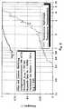
- Fig. 5
- eine Trennkurve, die den Einfluß der Zweistoffdüsen auf das Abscheideergebnis zeigt;
- Fig. 6
- eine Trennkurve der Anlage von Fig. 1 mit einer pneumatischen Zweistoffdüse mit innerer Mischung.
- Abgasmenge im Normzustand:
- 1200 m3/h
- Wasserbedarf L/G:
- 0,2 l/m3
- Abgastemperatur:
- 20 °C
- Düse mit innerer Mischung:
- 4,8 bar absolut
- Düse mit äußerer Mischung:
- 6,3 bar absolut
- Abgasmenge im Normzustand:
- 690 m3/h
- Wasserbedarf L/G:
- 0,25 l/m3
- Rohgaskonzentration:
- 204,9 mg/m3
- Düse mit innerer Mischung:
- 5,07 bar absolut,
Claims (23)
- Verfahren zur Abscheidung fester und/oder flüssiger Partikel, insbesondere mit kleinem Durchmesser, und/oder gasförmiger Komponenten aus einem Gasstrom durch gasdurchströmte Partikelabscheideaggregate (1, 11, 18, 19), deren Abscheidewirkung durch den Einsatz von feinst zerstäubter Waschflüssigkeit unterstützt wird, wobei der Gasstrom einem oder mehreren nebeneinander und/oder nacheinander angeordneten Partikelabscheideaggregaten (1, 11, 18, 19) zugeführt wird, in dessen bzw. deren Gaszuleitung (2) unmittelbar vor jedem gasdurchströmten Partikelabscheideaggregat (1, 11, 18, 19) Waschflüssigkeit mittels einer oder mehrerer pneumatischer, getrennt mit Zerstäubungsgas und Waschflüssigkeit angespeister Zweistoffdüsen (4, 15, 28) in Gasströmungsrichtung eingedüst wird,
dadurch gekennzeichnet, daß der zu reinigende Gasstrom vor dem Einbringen der Waschflüssigkeit mittels einer Gassättigungsstufe (17) mit Flüssigkeit gesättigt wird und die Geschwindigkeit der die Zweistoffdüsen (4, 15, 28) verlassenden Waschflüssigkeit höher ist als die Gasstromgeschwindigkeit. - Verfahren nach Anspruch 1, dadurch gekennzeichnet, daß als Partikelabscheideaggregat (1, 11, 18, 19) ein tangential angeströmter Zyklon, ein axial angeströmter Zyklon oder ein tangential oder axial angeströmter Multizyklon verwendet wird.
- Verfahren nach Anspruch 1, dadurch gekennzeichnet, daß als Partikelabscheideaggregat (1, 11, 18, 19) ein Massekraftabscheider, vorzugsweise ein Prallabscheider, Lamellenabscheider oder Ringspaltabscheider verwendet wird.
- Verfahren nach Anspruch 1, dadurch gekennzeichnet, daß als Partikelabscheideaggregat (1, 11, 18, 19) ein Wäscher, vorzugsweise ein Venturiwäscher, Wirbelwäscher oder Ringspaltwäscher verwendet wird.
- Verfahren nach einem der Ansprüche 1 bis 4, gekennzeichnet durch Zweistoffdüsen (4, 15, 28) mit innerer Vermischung.
- Verfahren nach einem der Ansprüche 1 bis 4, dadurch gekennzeichnet, daß die Betriebsparameter der pneumatischen Zweistoffdüsen (4), insbesondere der Düsendruck, in Abhängigkeit von der Abscheideleistung des Partikelabscheideaggregates (1, 11, 18, 19) von der durchgesetzten Gasmenge gesteuert werden.
- Verfahren nach Anspruch 1, dadurch gekennzeichnet, daß dem Gasstrom vor Eintritt in die Gassättigungsstufe (17) oder erste Partikelabscheidestufe (8) oder der Kreislaufwaschflüssigkeit der Gassättigungsstufe (17) feingemahlene schadstoffbindende Feststoffe zugegeben werden.
- Verfahren nach einem der Ansprüche 1 bis 7, dadurch gekennzeichnet, daß eine mehrstufige Kreislaufflüssigkeitsaufbereitung in die Gasreinigungsanlage integriert wird, bei der die einzelnen Flüssigkeitskreisläufe eines jeden Partikelabscheideaggregates (1, 11, 18, 19) voneinander vollkommen getrennt sind.
- Verfahren nach Anspruch 8, dadurch gekennzeichnet, daß in einen oder mehreren der getrennten Flüssigkeitskreisläufe jeweils eine Sedimentationsstufe (33, 35, 36) zur Abtrennung der enthaltenen ungelösten Partikel geschaltet ist.
- Verfahren nach Anspruch 8 oder 9, dadurch gekennzeichnet, daß die Konzentration an gelösten Stoffen in den Kreislaufflüssigkeiten hintereinandergeschalteter Verfahrensstufen der Kreislaufflüssigkeitsaufbereitung entgegen der Gasdurchlaufrichtung durch kontrollierte Flüssigkeitsüberleitung (37) in die jeweils vorhergeschaltete Stufe, durch alleinige Ergänzung von verdunsteter Flüssigkeit in der in Gasdurchlaufrichtung letzten Partikelabscheidestufe (30) und durch alleinige Flüssigkeitsausschleusung (38) zum Austrag von gelösten Stoffen aus der ersten Verfarhrensstufe der Kreislaufflüssigkeitsaufbereitung zunimmt.
- Verfahren nach einem der Ansprüche 8 bis 10, dadurch gekennzeichnet, daß die Konzentration an gelösten Salzen in der in Gasdurchlaufrichtung ersten Stufe der Kreislaufflüssigkeitsaufbereitung knapp unter der Löslichkeitsgrenze gehalten wird und daß ein Teil der Kreislaufflüssigkeit dieser Stufe über ein gekühltes Kristallisationsbecken (39) im Kreis geführt wird.
- Verfahren nach Anspruch 11, dadurch gekennzeichnet, daß die zur Austragung von gelösten Stoffen ausgeschleuste Flüssigkeitsmenge durch mehrstufige Aufbereitung aufgearbeitet wird, wobei durch kontrollierte Zugabe von Fällungschemikalien (41, 43) in mehreren Stufen (20, 22) die in der Flüssigkeit gelösten Wertstoffe und Schwermetalle nacheinander ausgefällt und gewonnen werden.
- Verfahren nach Anspruch 12, dadurch gekennzeichnet, daß in einer oder mehreren Fällungsstufen (20, 22) zusätzlich noch wertstoffhaltige Reststoffe zur Aufarbeitung zugegeben werden.
- Verfahren nach Anspruch 12, dadurch gekennzeichnet, daß ein Teil des Klarlaufes (42) der ersten Fällungsstufe (20) in den Flüssigkeitskreislauf der in Gasdurchlaufrichtung letzten Partikelabscheidestufe (30) zur Einstellung des gewünschten pH-Wertes der Kreislaufflüssigkeit geleitet wird.
- Verfahren nach Anspruch 12, dadurch gekennzeichnet, daß der Klarlauf der letzen Fällungsstufe (22) einer Kristallisationsstufe (24) zur Gewinnung der gelösten Salze zugeführt wird, wobei wahlweise eine teilweise Eindampfung mit Rückführung der verbleibenden Flüssigkeit in den Flüssigkeitskreislauf der Gassättigungsstufe (17) oder ersten Partikelabscheidestufe (19) oder eine vollständige Eindampfung des Klarlaufes durchgeführt wird.
- Verfahren nach Anspruch 15, dadurch gekennzeichnet, daß vor der Kristallisationsstufe (24) eine geeignete Umsalzungsstufe, vorzugsweise eine Fällung von Kalziumkarbonat mit Kohlendioxid oder einem löslichen Karbonat mit Rückführung der gewonnenen Kalziumkarbonatsuspension in die erste Fällungsstufe (20), vorgeschaltet wird.
- Verfahren nach Anspruch 12, dadurch gekennzeichnet, daß der Klarlauf der letzten Fällungsstufe (22) einem Sprühtrockner zugeführt wird.
- Anlage zur Durchführung des Verfahrens nach Anspruch 1, dadurch gekennzeichnet, daß die Anlage ein oder mehrere nebeneinander und/oder nacheinander angeordneten Partikelabscheideaggregate (1, 11, 18, 19) aufweist, daß jedem gasdurchströmten Partikelabscheideaggregat (1, 11, 18, 19) in Gasströmungsrichtung eine oder mehrere pneumatische Zweistoffdüsen (4, 15, 28) unmittelbar vorgeschaltet sind, die die Waschflüssigkeit in Gasströmungsrichtung in den Gasstrom in feinstgeteilter Form eindüsen, wobei jede Zweistoffdüse (4, 15, 28) getrennt mit Zerstäubungsgas und Waschflüssigkeit angespeist wird, und daß zur Sättigung des Gasstromes mit Flüssigkeit in Gasströmungsrichtung vor der ersten Zweistoffdüse (28) eine Gassättigungsstufe (17) vorgesehen ist.
- Anlage nach Anspruch 18, dadurch gekennzeichnet, daß eine oder mehrere Zweistoffdüsen (4, 15, 28) in einer vorzugsweise normal zur Gasströmungsrichtung liegenden Düsenebene, oder mehrere Zweistoffdüsen und/oder Düsenebenen hintereinander und/oder räumlich versetzt in der Gaszuleitung des Partikelabscheideaggregates angeordnet sind.
- Anlage nach Anspruch 18, dadurch gekennzeichnet, daß jede Partikelabscheidestufe (18, 19) mit einer mehrstufigen Kreislaufflüssigkeitsaufbereitungsvorrichtung verbunden ist, und daß die einzelnen Kreislaufflüssigkeitsaufbereitungsvorrichtungen voneinander vollkommen getrennt sind.
- Anlage nach Anspruch 20, dadurch gekennzeichnet, daß in eine oder mehrere der getrennten Flüssigkeitskreisläufe jeweils eine Sedimentationsstufe (33, 35, 36) eingebaut ist.
- Anlage nach Anspruch 20, dadurch gekennzeichnet, daß in der in Gasdurchlaufrichtung ersten Kreislaufflüssigkeitsaufbereitungsvorrichtung (17) für einen Teil der Kreislaufflüssigkeit ein gekühltes Kristallisationsbecken (39) vorgesehen ist.
- Anlage nach Anspruch 18, dadurch gekennzeichnet, daß zur Sättigung des Gasstromes mit Flüssigkeit ein Quench eingesetzt ist, und daß sich der in der Gasaustrittsleitung des Quench befindliche Tropfenabscheider (27) direkt vor der ersten Zweistoffdüse oder Düsenebene (28) des nachfolgenden Partikelabscheideaggregates (18) befindet, wodurch sich für diese Zweistoffdüse oder Düsenebene (28) eine sehr gleichmäßige Gasströmung ergibt.
Priority Applications (1)
| Application Number | Priority Date | Filing Date | Title |
|---|---|---|---|
| AT93905303T ATE180989T1 (de) | 1993-03-05 | 1993-03-05 | Verfahren und anlage zur abgasreinigung, sowie kombination dieser abgasreinigung mit einer abwasserreinigung |
Applications Claiming Priority (1)
| Application Number | Priority Date | Filing Date | Title |
|---|---|---|---|
| PCT/EP1993/000502 WO1994020196A1 (de) | 1993-03-05 | 1993-03-05 | Verfahren und anlage zur abgasreinigung, sowie kombination dieser abgasreinigung mit einer abwasserreinigung |
Publications (2)
| Publication Number | Publication Date |
|---|---|
| EP0639104A1 EP0639104A1 (de) | 1995-02-22 |
| EP0639104B1 true EP0639104B1 (de) | 1999-06-09 |
Family
ID=8165709
Family Applications (1)
| Application Number | Title | Priority Date | Filing Date |
|---|---|---|---|
| EP93905303A Expired - Lifetime EP0639104B1 (de) | 1993-03-05 | 1993-03-05 | Verfahren und anlage zur abgasreinigung, sowie kombination dieser abgasreinigung mit einer abwasserreinigung |
Country Status (6)
| Country | Link |
|---|---|
| EP (1) | EP0639104B1 (de) |
| JP (1) | JPH07507008A (de) |
| KR (1) | KR950701245A (de) |
| AU (1) | AU672966B2 (de) |
| DE (1) | DE59309643D1 (de) |
| WO (1) | WO1994020196A1 (de) |
Families Citing this family (2)
| Publication number | Priority date | Publication date | Assignee | Title |
|---|---|---|---|---|
| NL1015635C2 (nl) * | 2000-07-06 | 2002-01-08 | Korea Clean Air System Co | Luchtreinigingsinrichting voor het verwijderen van luchtverontreiniging m.b.v. een waterversproeiingstype stofverzamelingssyteem. |
| CN118022385A (zh) * | 2023-11-30 | 2024-05-14 | 爱彼爱和新材料有限公司 | 一种超临界二氧化碳干燥方法 |
Family Cites Families (6)
| Publication number | Priority date | Publication date | Assignee | Title |
|---|---|---|---|---|
| ES417140A1 (es) * | 1972-07-21 | 1976-04-01 | Gardenier Hugh Emory | Procedimiento y aparato para extraer gases contaminados de una fuente a traves de medios de conducto y eliminar de las mismas particulas contaminantes. |
| AU496281B2 (en) * | 1976-05-18 | 1977-11-24 | Teller Environmental Systems, Inc | Process for removing particulates froma gas |
| CA1091144A (en) * | 1977-03-03 | 1980-12-09 | Cominco Ltd. | Wet gas scrubber for micron and sub-micron particulates |
| DE3507536A1 (de) * | 1985-03-04 | 1987-01-08 | Baumco Handel & Engineering Gm | Verfahren und vorrichtung zur entfernung von gasfoermigen kohlenwasserstoffen aus luft oder anderen traegergasen |
| DE3535600C1 (de) * | 1985-10-05 | 1987-05-27 | Perfluktiv Consult Ag | Verfahren zur Verminderung des Schadstoffgehaltes von staubhaltigen Rauch- oder Prozessgasen |
| WO1993000147A1 (de) * | 1991-06-28 | 1993-01-07 | Voest-Alpine Industrieanlagenbau Gesellschaft M.B.H. | Verfahren zur abtrennung von festen und/oder flüssigen teilchen und/oder von schadgas aus einem gasstrom und anlage zur durchführung des verfahrens |
-
1993
- 1993-03-05 JP JP6519494A patent/JPH07507008A/ja active Pending
- 1993-03-05 KR KR1019940703855A patent/KR950701245A/ko not_active Withdrawn
- 1993-03-05 EP EP93905303A patent/EP0639104B1/de not_active Expired - Lifetime
- 1993-03-05 DE DE59309643T patent/DE59309643D1/de not_active Expired - Fee Related
- 1993-03-05 AU AU36311/93A patent/AU672966B2/en not_active Ceased
- 1993-03-05 WO PCT/EP1993/000502 patent/WO1994020196A1/de not_active Ceased
Also Published As
| Publication number | Publication date |
|---|---|
| AU3631193A (en) | 1994-09-26 |
| WO1994020196A1 (de) | 1994-09-15 |
| EP0639104A1 (de) | 1995-02-22 |
| KR950701245A (ko) | 1995-03-23 |
| DE59309643D1 (de) | 1999-07-15 |
| JPH07507008A (ja) | 1995-08-03 |
| AU672966B2 (en) | 1996-10-24 |
Similar Documents
| Publication | Publication Date | Title |
|---|---|---|
| DE970433C (de) | Verfahren und Vorrichtung zur Entfernung von feinverteilter suspendierter Materie aus Gasen | |
| US5427608A (en) | Method of separating solid and/or liquid particles and/or polluting gas from a gas stream, and apparatus for carrying out the method | |
| DE69524594T2 (de) | Verbesserte flugstromtrennvorrichtung für gase von hoher geschwindigkeit und zur wiederaufheizung von wäschergasen | |
| DD215573A5 (de) | Verfahren und vorrichtung zur beseitigung von schwefeloxiden aus heissem rauchgas | |
| DE69125007T2 (de) | Verfahren, vorrichtung und system für die behandlung von rauchgas | |
| DD236751A5 (de) | Verfahren und einrichtung zum abkuehlen und entstauben von gasen | |
| DE2907177A1 (de) | Verfahren zur entfernung von schwefeloxiden aus abgasen | |
| CH676089A5 (de) | ||
| EP2749341B1 (de) | Vorrichtung und verfahren zum reinigen von rauchgas einer metallurgischen anlage | |
| DE68918706T2 (de) | Verfahren und vorrichtung zur trockenentfernung von verunreinigungen aus gasströmen. | |
| DE69201587T2 (de) | Wäscher für mehrere Gase. | |
| DE2519996A1 (de) | Vorrichtung und verfahren zum inberuehrungbringen zweier fluide | |
| DE1274560B (de) | Vorrichtung zum Entstauben von Industriegasen | |
| EP0800851B1 (de) | Verfahren zur Reinigung schadstoffbelasteter Spannrahmen-Abluft | |
| DE69103747T2 (de) | Methode und vorrichtung zur reinigung von abgasen. | |
| DE3325140A1 (de) | Verfahren zur reinigung von staub- und aerosolhaltigen gasen und/oder daempfen sowie anlage zur durchfuehrung des verfahrens | |
| EP0639104A1 (de) | Verfahren und anlage zur abgasreinigung, sowie kombination dieser abgasreinigung mit einer abwasserreinigung | |
| EP0545943B1 (de) | Verfahren zur abtrennung von festen und/oder flüssigen und/oder gasförmigen teilchen aus einem gasstrom und anlage zur durchführung des verfahrens | |
| DE68924767T2 (de) | Verfahren und apparat für intimes mischen von flüssigkeiten. | |
| DE2652365A1 (de) | Verfahren und vorrichtung zur entfernung von verunreinigungen aus einem gasstrom | |
| EP3021955B1 (de) | Verfahren und vorrichtung zur reinigung von abluft | |
| DE2731755A1 (de) | Vorrichtung zur reinigung von abluft- und prozessgasstroemen | |
| EP0221403A2 (de) | Verfahren zur Abscheidung von gasförmigen Verunreinigungen aus Rauchgasen und Vorrichtung hierzu | |
| DE3135428C2 (de) | Verfahren zur Rauchgasreinigung, insbesondere von Rauchgasen von Lebensmittelräucheranlagen, und Vorrichtung zur Durchführung des Verfahrens | |
| EP0046195B1 (de) | Verfahren und Vorrichtung zur Abtrennung von flüssigem Harnstoff aus den Abgasen der Melaminsynthese |
Legal Events
| Date | Code | Title | Description |
|---|---|---|---|
| PUAI | Public reference made under article 153(3) epc to a published international application that has entered the european phase |
Free format text: ORIGINAL CODE: 0009012 |
|
| 17P | Request for examination filed |
Effective date: 19941124 |
|
| AK | Designated contracting states |
Kind code of ref document: A1 Designated state(s): AT BE DE DK ES FR GB IT LU NL SE |
|
| 17Q | First examination report despatched |
Effective date: 19950905 |
|
| GRAG | Despatch of communication of intention to grant |
Free format text: ORIGINAL CODE: EPIDOS AGRA |
|
| GRAG | Despatch of communication of intention to grant |
Free format text: ORIGINAL CODE: EPIDOS AGRA |
|
| GRAH | Despatch of communication of intention to grant a patent |
Free format text: ORIGINAL CODE: EPIDOS IGRA |
|
| GRAH | Despatch of communication of intention to grant a patent |
Free format text: ORIGINAL CODE: EPIDOS IGRA |
|
| GRAA | (expected) grant |
Free format text: ORIGINAL CODE: 0009210 |
|
| AK | Designated contracting states |
Kind code of ref document: B1 Designated state(s): AT BE DE DK ES FR GB IT LU NL SE |
|
| PG25 | Lapsed in a contracting state [announced via postgrant information from national office to epo] |
Ref country code: NL Free format text: LAPSE BECAUSE OF FAILURE TO SUBMIT A TRANSLATION OF THE DESCRIPTION OR TO PAY THE FEE WITHIN THE PRESCRIBED TIME-LIMIT Effective date: 19990609 Ref country code: IT Free format text: LAPSE BECAUSE OF FAILURE TO SUBMIT A TRANSLATION OF THE DESCRIPTION OR TO PAY THE FEE WITHIN THE PRE;WARNING: LAPSES OF ITALIAN PATENTS WITH EFFECTIVE DATE BEFORE 2007 MAY HAVE OCCURRED AT ANY TIME BEFORE 2007. THE CORRECT EFFECTIVE DATE MAY BE DIFFERENT FROM THE ONE RECORDED.SCRIBED TIME-LIMIT Effective date: 19990609 Ref country code: GB Free format text: LAPSE BECAUSE OF FAILURE TO SUBMIT A TRANSLATION OF THE DESCRIPTION OR TO PAY THE FEE WITHIN THE PRESCRIBED TIME-LIMIT Effective date: 19990609 Ref country code: FR Free format text: LAPSE BECAUSE OF FAILURE TO SUBMIT A TRANSLATION OF THE DESCRIPTION OR TO PAY THE FEE WITHIN THE PRESCRIBED TIME-LIMIT Effective date: 19990609 Ref country code: ES Free format text: THE PATENT HAS BEEN ANNULLED BY A DECISION OF A NATIONAL AUTHORITY Effective date: 19990609 |
|
| REF | Corresponds to: |
Ref document number: 180989 Country of ref document: AT Date of ref document: 19990615 Kind code of ref document: T |
|
| REF | Corresponds to: |
Ref document number: 59309643 Country of ref document: DE Date of ref document: 19990715 |
|
| PG25 | Lapsed in a contracting state [announced via postgrant information from national office to epo] |
Ref country code: DK Free format text: LAPSE BECAUSE OF FAILURE TO SUBMIT A TRANSLATION OF THE DESCRIPTION OR TO PAY THE FEE WITHIN THE PRESCRIBED TIME-LIMIT Effective date: 19990909 |
|
| EN | Fr: translation not filed | ||
| GBV | Gb: ep patent (uk) treated as always having been void in accordance with gb section 77(7)/1977 [no translation filed] |
Effective date: 19990609 |
|
| PG25 | Lapsed in a contracting state [announced via postgrant information from national office to epo] |
Ref country code: LU Free format text: LAPSE BECAUSE OF NON-PAYMENT OF DUE FEES Effective date: 20000305 Ref country code: AT Free format text: LAPSE BECAUSE OF NON-PAYMENT OF DUE FEES Effective date: 20000305 |
|
| PGFP | Annual fee paid to national office [announced via postgrant information from national office to epo] |
Ref country code: BE Payment date: 20000317 Year of fee payment: 8 |
|
| PLBE | No opposition filed within time limit |
Free format text: ORIGINAL CODE: 0009261 |
|
| STAA | Information on the status of an ep patent application or granted ep patent |
Free format text: STATUS: NO OPPOSITION FILED WITHIN TIME LIMIT |
|
| 26N | No opposition filed | ||
| PG25 | Lapsed in a contracting state [announced via postgrant information from national office to epo] |
Ref country code: BE Free format text: LAPSE BECAUSE OF NON-PAYMENT OF DUE FEES Effective date: 20010331 |
|
| BERE | Be: lapsed |
Owner name: VOEST-ALPINE INDUSTRIEANLAGENBAU G.M.B.H. Effective date: 20010331 |
|
| PGFP | Annual fee paid to national office [announced via postgrant information from national office to epo] |
Ref country code: SE Payment date: 20040302 Year of fee payment: 12 |
|
| PG25 | Lapsed in a contracting state [announced via postgrant information from national office to epo] |
Ref country code: SE Free format text: LAPSE BECAUSE OF NON-PAYMENT OF DUE FEES Effective date: 20050306 |
|
| EUG | Se: european patent has lapsed | ||
| PGFP | Annual fee paid to national office [announced via postgrant information from national office to epo] |
Ref country code: DE Payment date: 20090518 Year of fee payment: 17 |
|
| PG25 | Lapsed in a contracting state [announced via postgrant information from national office to epo] |
Ref country code: DE Free format text: LAPSE BECAUSE OF NON-PAYMENT OF DUE FEES Effective date: 20101001 |