EP0638956B1 - Antenne active à balayage électronique en azimut et en élévation, en particulier pour l'imagerie hyperfréquence par satellite - Google Patents
Antenne active à balayage électronique en azimut et en élévation, en particulier pour l'imagerie hyperfréquence par satellite Download PDFInfo
- Publication number
- EP0638956B1 EP0638956B1 EP19940401772 EP94401772A EP0638956B1 EP 0638956 B1 EP0638956 B1 EP 0638956B1 EP 19940401772 EP19940401772 EP 19940401772 EP 94401772 A EP94401772 A EP 94401772A EP 0638956 B1 EP0638956 B1 EP 0638956B1
- Authority
- EP
- European Patent Office
- Prior art keywords
- sources
- reflector
- collector
- antenna
- array
- Prior art date
- Legal status (The legal status is an assumption and is not a legal conclusion. Google has not performed a legal analysis and makes no representation as to the accuracy of the status listed.)
- Expired - Lifetime
Links
- 238000003384 imaging method Methods 0.000 title description 2
- 230000005855 radiation Effects 0.000 claims description 15
- 238000003491 array Methods 0.000 claims 1
- 230000005540 biological transmission Effects 0.000 description 5
- 238000006073 displacement reaction Methods 0.000 description 4
- 230000003321 amplification Effects 0.000 description 2
- 230000015572 biosynthetic process Effects 0.000 description 2
- 238000010276 construction Methods 0.000 description 2
- 230000005284 excitation Effects 0.000 description 2
- 238000000034 method Methods 0.000 description 2
- 238000003199 nucleic acid amplification method Methods 0.000 description 2
- 230000003071 parasitic effect Effects 0.000 description 2
- 238000003786 synthesis reaction Methods 0.000 description 2
- 241000287107 Passer Species 0.000 description 1
- 230000002238 attenuated effect Effects 0.000 description 1
- 230000015556 catabolic process Effects 0.000 description 1
- 239000012141 concentrate Substances 0.000 description 1
- 238000006731 degradation reaction Methods 0.000 description 1
- 230000001066 destructive effect Effects 0.000 description 1
- 230000001627 detrimental effect Effects 0.000 description 1
- 238000009826 distribution Methods 0.000 description 1
- 230000005670 electromagnetic radiation Effects 0.000 description 1
- 230000017525 heat dissipation Effects 0.000 description 1
- 238000002955 isolation Methods 0.000 description 1
- 239000000463 material Substances 0.000 description 1
- 238000005259 measurement Methods 0.000 description 1
- 230000003287 optical effect Effects 0.000 description 1
- 230000010363 phase shift Effects 0.000 description 1
- 238000005070 sampling Methods 0.000 description 1
- 238000010408 sweeping Methods 0.000 description 1
Images

Classifications
-
- H—ELECTRICITY
- H01—ELECTRIC ELEMENTS
- H01Q—ANTENNAS, i.e. RADIO AERIALS
- H01Q3/00—Arrangements for changing or varying the orientation or the shape of the directional pattern of the waves radiated from an antenna or antenna system
- H01Q3/26—Arrangements for changing or varying the orientation or the shape of the directional pattern of the waves radiated from an antenna or antenna system varying the relative phase or relative amplitude of energisation between two or more active radiating elements; varying the distribution of energy across a radiating aperture
- H01Q3/2658—Phased-array fed focussing structure
-
- H—ELECTRICITY
- H01—ELECTRIC ELEMENTS
- H01Q—ANTENNAS, i.e. RADIO AERIALS
- H01Q19/00—Combinations of primary active antenna elements and units with secondary devices, e.g. with quasi-optical devices, for giving the antenna a desired directional characteristic
- H01Q19/10—Combinations of primary active antenna elements and units with secondary devices, e.g. with quasi-optical devices, for giving the antenna a desired directional characteristic using reflecting surfaces
- H01Q19/18—Combinations of primary active antenna elements and units with secondary devices, e.g. with quasi-optical devices, for giving the antenna a desired directional characteristic using reflecting surfaces having two or more spaced reflecting surfaces
- H01Q19/19—Combinations of primary active antenna elements and units with secondary devices, e.g. with quasi-optical devices, for giving the antenna a desired directional characteristic using reflecting surfaces having two or more spaced reflecting surfaces comprising one main concave reflecting surface associated with an auxiliary reflecting surface
- H01Q19/192—Combinations of primary active antenna elements and units with secondary devices, e.g. with quasi-optical devices, for giving the antenna a desired directional characteristic using reflecting surfaces having two or more spaced reflecting surfaces comprising one main concave reflecting surface associated with an auxiliary reflecting surface with dual offset reflectors
-
- H—ELECTRICITY
- H01—ELECTRIC ELEMENTS
- H01Q—ANTENNAS, i.e. RADIO AERIALS
- H01Q25/00—Antennas or antenna systems providing at least two radiating patterns
- H01Q25/007—Antennas or antenna systems providing at least two radiating patterns using two or more primary active elements in the focal region of a focusing device
- H01Q25/008—Antennas or antenna systems providing at least two radiating patterns using two or more primary active elements in the focal region of a focusing device lens fed multibeam arrays
Definitions
- the field of the invention is that of antennas active with electronic scanning, and more particularly antennas whose effective opening must be wide by relation to the dimensions of the network of elementary sources radiating.
- Such an antenna is generally constituted a reflector of an appropriate shape, illuminated by a network of elementary sources including the relative phases can be controlled to direct the beam around of an average direction.
- the invention will be particularly adapted to obtain decisive advantages when applied in the field of antennas on board satellite, for example for imaging applications radar.
- the invention can also be used on board airplanes or any other aircraft for applications radar imagery.
- the antenna according to the invention can also be suitable for terrestrial applications which require an electronic scan along one or two orthogonal axes.
- the satellite orbit parameters do not allow not to fly over a specific place at a given time; the observation of a given place must wait until the satellite is above this place.
- the antenna of a SAR radar must be orientable to aim at the desired place, even if it is slightly offset from the satellite position.
- the sighting directions are defined relative to the trajectory from the satellite: the azimuth in the orbit plane, that is to say in front of and behind the vertical; and the elevation in a plane perpendicular to the plane of the orbit and the trajectory of the satellite, that is to say the target lateral on each side of the orbit plane.
- the beam of electromagnetic radiation is electronically orientable, without physical displacement of the antenna relative to the platform, whether it's a satellite or aircraft.
- SAR SAR
- several antenna performance parameters are particularly critical, particularly with regard to radiation pattern.
- the antenna design is pushed into the sense of very weak side lobes, in any case good less than -20 dB compared to the main lobe, and one lobe main narrow with steep sides.
- scanning beam electronics these qualities must be kept to avoid possible degradation of the image quality.
- this finesse of control is obtained by sampling relatively thin on the network surface.
- Each network sample consists of one or more radiating elements, and the phase characteristic of the wave emitted or received by this sample is adjusted by a microwave phase shifting equipment.
- a radiation array antenna direct that meets system specifications on-board microwave radar imagery circulating around the earth in low orbit, typically a radiant surface of the order of 200 x 500 cm and a number of samples of the order of 4000.
- phase shifters are variable phase shifters, so you have to provide 8000 control circuits to carry out the beam shape and electronic scanning as well as a electronic order calculation and addressing for calculate and then apply the appropriate values to phase shifters in order to obtain the appropriate parameters of the beam.
- a reflector antenna In the case of a radar on board a satellite in orbit low, the antenna scanning ranges are a few degrees in azimuth, and a few tens of degrees in elevation. These parameters lead to the use of a reflector having a cylindro-parabolic shape with its generators substantially perpendicular to the direction instantaneous movement of the satellite. The difference between the extent of the azimuth and elevation, as well as the cylindro-parabolic shape of the reflector, introduce an asymmetry between the measurements to take to ensure the azimuth scan, on the one hand, and elevation scanning, on the other hand. Although the means employees in both cases are similar, for clarity from the discussion that follows we will deal with these two meanings orthogonal scan separately.
- the relative provision of the emitting source and the reflector on board the satellite is usually of a so-called "offset" geometry, according to which the emitting source, which is substantially at the focus of the reflector, is offset from the beam finally radiated after reflection on this cylindro-parabolic reflector.
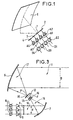
- a cylindro-parabolic reflector antenna 5 including the offset plan, in which is carried out the azimuth scan, is the plane which contains the line and curve drawn in dotted lines.
- a linear network of sources elementary (1,2,3,4) with the straight line which connects the geometric centers of these sources arranged in the same plane as the line and curve drawn in dotted lines.
- the main transmitting (or receiving) source considered is source 1, constituted for example by a horn placed on the focal line (not shown) of the reflector 5.
- This source 1 is supplied by via an A1 amplifier with adjustable gain, as well than an adjustable phase shifter D1.
- This source 1 taken in isolation normally appears, on both sides the main lobe, two parasitic secondary lobes at -17 dB that it is necessary to delete in the case of a mission SAR.
- This removal of side lobes is performed by the use of two other sources (2,3) which are arranged on either side of the main source 1.
- These two sources are also supplied via an adjustable amplifier and phase shifter, respectively A2, D2, A3, D3. They are each slightly deviated from the pointing direction from main source 1, and more specifically they are pointed respectively in the direction of the two lobes secondary on either side of the main lobe of the main source 1.
- Adjustable phase shifters and amplifiers A2, D2, A3, D3 of this known device are adjusted to give these secondary sources 2, 3 an amplitude of -17 dB compared at main source 1, but in phase opposition with the main radiation lobe of the latter, so as to cancel these side lobes by destructive interference.
- source 3 At nominal power at source main, and sources 1 and 4 with an amplitude of -17 dB and in phase opposition to cancel the lobes secondary source 3.
- the displacement of the axis of the radiation emitted towards the reflector results in a depointing according to an azimuth angle determined by the relative geometry of the sources and the reflector.
- This device is capable of transmitting (or receiving) the radar beam under the conditions required for the SAR mission, however there are still some issues that are concerns for radars on board platforms airborne or spaceborne.
- a reflector antenna of the known art is partially and schematically represented on the figure 2. Only the parts necessary to obtain the elevation scan are shown in this figure 2.
- the elevation scan must be possible on an area of several dozen openings to beam half power to provide ground coverage desired between two successive traces of passage of the satellite around the surface of the earth.
- the non-deflected beam is represented by the lines 22,21,23,24 which are directed parallel to the reflector 5.
- the radiation from the source 4, according to line 24, is not useful because not reflected by the reflector 5. It is therefore necessary to give a power null (using the A4 amplifier, for example) at this source when it comes to radiating in this direction.
- this active network 6 then comprises a source additional 4, aligned with the other three and it also associated with an adjustable amplifier and phase shifter A4, D4. As mentioned above, this source 4 will only powered only in the case of a depointing.
- the A4 amplifier is set to a non-zero gain, and the gain of amplifier A2 is set to a value nothing.
- amplifiers must work in a very wide gain range, which is detrimental from the point of view of mass and energy efficiency, therefore power consumption and heat dissipation.
- the antenna described in this document has two parabolic reflectors and an electromagnetic lens arranged in their common home. This structure is arranged in a periscopic configuration which reduces the dimensions of the active network 6.
- the lens electromagnetic allows to dissociate the radio constraints necessary to ensure required antenna performance, that of mechanical locations of the elements constituting the antenna.
- fine adjustment phase shifters installed at the within this electromagnetic lens allow to adjust parameters of the emitted beam to ensure that the better the direct line telecommunications mission.
- over-the-air telecommunications microwave occurs in direct line of sight between a transmitting antenna and a remote receiving antenna. The direction of radiation is fixed according to this line of sight direct, so the antenna described by this document is not able to fulfill the SAR mission described above.
- the two faces of said lens are parallel.
- the two faces of said radio lens are not not parallel.
- the network collector is smaller than the network primary, although both networks have the same number of sources. According to one characteristic, the sources of the collector network are smaller than the sources of the primary network.
- transmit antennas are also strictly transferable, provided the power flow is reversed in the device, to receiving antennas.
- the same physical device will generally called upon to fulfill the two emission roles and reception ; however, it is necessary to plan two chains amplification, one to provide amplification of power required for transmission, and the other for amplify the very weak signals received after reflection from the signal from the radar target.
- the treatment of both channels, reception and transmission is perfectly symmetrical except for this detail, and for the clarity of the description which follows, it suffices to describe only the path transmission, knowing that the inversion in reception channel can be unambiguously deduced therefrom by those skilled in the art.
- Such an antenna uses the periscope principle optical, and it includes an active network 6, of dimensions reduced compared to an active direct radiation network capable of providing the same beam dimensions, by example section D radiated by the double antenna "offset" configuration reflectors.
- the beam 10 of section "d" which is radiated by the network active 6 is normally reflected by a first reflector cylindro-parabolic 7 called “auxiliary reflector”, which concentrates in his home, which in a Gregory antenna classic, coincides with the focus of the second reflector 5 says “main reflector”.
- auxiliary reflector a first reflector cylindro-parabolic 7 which concentrates in his home, which in a Gregory antenna classic, coincides with the focus of the second reflector 5 says “main reflector”.
- the beam after reflection and concentration by the auxiliary reflector 7 propagates by diverging to illuminate the main reflector 5 from where it is reflected in a beam 11 of section D in parallel rays.
- the antenna is called "offset" because of the offset between the beam 10 emitted by the network of sources elementary 6, and the beam 11 finally radiated.
- the elements of the Gregory antenna which have just been described are conventional.
- the antenna according to the invention is distinguished by the special characteristics which will now described.
- phase shifters 8 serve well known, to point out at will the direction of the beam 10 emitted by the active network 6.
- These phase shifters are tracked power amplifiers 9 in the case of an antenna with emission, which, unlike amplifiers A1, A2, A3, A4 of figure 1, are amplifiers that work all with a fixed and predetermined gain.
- the "small" receiving sources of the collector 13 are correspond one by one, geographically homothetic, with the "large” re-emitting sources of the primary network 15, i.e. the distributions respective of these sources are the same on each network 13, 15.
- a source of the collector 13 is connected to the source geographically corresponding to the primary network 15 by via a connector 16.
- Other phase shifters adjustable can be provided inside the lens between the collector 13 and the primary network 15 (marked 18 in Figure 4).
- the primary network 15 is positioned in the plane focal point of the focal point F 'of the reflector 5, while the collector 13 is placed in the focal plane of the focal point F of the reflector 7.
- the collector 13 is, in the example of this figure, in is quite close to the primary network 15 and, in first approximation, the two dishes 7 and 5 can be considered confocal, as in the Gregory antenna classic.
- the connection between the collector 13 and the primary network 15 allows flexibility of arrangement of the collector 13 and the primary network 15, which can be moved away from each other, or arranged in a non-parallel configuration (not shown).
- the beams 10,14,17, and 11 are as shown in FIG. 3.
- the characteristics of the lens 12, and in particular the relative dimensions of the sources of the collector 13 and the primary network 15, are such that the conditions amplitudes and phases mentioned above are respected for the sources of the primary network: considering (figure 1) a source 1 assumed for example at the point marked F 'on the primary network of FIG. 3, this source is associated, on both sides, at two depointed sources 2 and 3 which are in phase and re-emitting at 17 dB below, so that ultimately the two parasitic side lobes of the source 1, at the point marked F ', are compensated for and therefore practically erased.
- the auxiliary reflector 7 reflects a beam 14 which is itself also devoid of his initial focal task. he no longer focuses on the point marked F 'but on a neighboring source which will therefore collect a maximum of energy whereas the source located at the aforementioned point F now goes collect much less energy.
- FIG. 4 we see another example of a embodiment according to the invention of a scanning antenna electronic in azimuth and elevation.
- This figure is identical to FIG. 3 already described, except for the phase shifters 18 within the electronic lens 12.
- This variant is particularly advantageous in the case of a elevation electronic scanning with a wide angle of travel.
- the phase shifters 8 are used to obtain the electronic scanning of the beam.
- the additional phase shifters 18 within the radio lens can be used to bring end of beam tracing settings, which changes to as a function of the lateral viewing angle.
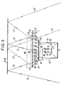
- FIG. 5 represents a section in a plane which contains a generator of each of the cylindro-parabolic reflectors, and which shows in more detail the principle of elevation scanning.
- the primary network 15 consists of a core central N1 of emitting sources which form, for this network 15 the central focal task F ′ (FIG. 4).
- the beam 17 is emitted towards the reflector 5 by this central core N1 of elementary sources, and partially reflected according to the undepointed beam 11 ( Figures 4 and 5).
- This central core N1 is framed by and other by additional sources S1, S2 which, as as we will see below, do not emit energy in the absence of elevation scanning.
- the collector 13 is homothetic to the primary network 15, and therefore comprises the same number of sources distributed in the same way, that is to say according to a central nucleus n1, homologous to the nucleus N1 but smaller, framed by sources s1, s2 homologs respectively of sources S1, S2.
- the dimensional characteristics of the auxiliary reflector 7 and of the manifold 13 are determined so that in the absence of electronic scanning, the focal spot F which is illuminated by the reflected beam 14 corresponds to the central core cited above n1.
- the sources s1, s2 do not therefore receive no energy from reflector 7 so that the sources s1, s2 do not retransmit no energy towards the reflector 5.
- a depointing in beam elevation 11 without overflow losses acts on the one hand on the adjustable phase shifters 8 for spot beam 10, and therefore also beam 14 as as indicated at 14 in FIG. 5, in order to shift, by example to the left (fig.5) this beam 14. It results in a concomitant shift, to the left, of the nucleus of sources then illuminated by this beam 14 ', this nucleus passing from position n1 to offset position n2 including now s1 side sources but no longer including sources s3, in number corresponding to s1, from the end right of nucleus n1.
- nucleus N1 is displaced, on the primary network 15, to the left along the nucleus N2 repeater, which includes S1 sources but no longer sources S3, respectively homologous to nucleus n2 and sources s1 and s3.
- the emissive focal spot being thus shifted, on the primary network 15, from N1 to N2, it then becomes possible perform an elevation scan of the radiated beam 17.11 without risking loss by overflow.
- This sweep is achieved by fine adjustment of phase shifts due to adjustable phase shifters 18, and the beam re-emitted and directed by the focal task N2 is designated by the references 17 ', while the beam finally radiated to the surface terrestrial is designated by the references 11 '.
Landscapes
- Variable-Direction Aerials And Aerial Arrays (AREA)
- Aerials With Secondary Devices (AREA)
Description
- un réseau de sources élémentaires, chaque source élémentaire étant alimentée par l'intermédiaire d'un amplificateur et d'un déphaseur réglable ;
- un premier et un deuxième réflecteurs cylindro-parabolique ; et
- une lentille radioélectrique ayant deux faces :
- une première face comportant un premier réseau de sources dit "collecteur" qui reçoit et capte un faisceau concentré réfléchi par ledit premier réflecteur, à partir du faisceau émis par ledit réseau de sources élémentaires, ce collecteur étant disposé au foyer dudit premier réflecteur,
- une deuxième face comportant un deuxième réseau de sources dit "réseau primaire" disposé au foyer dudit deuxième réflecteur, qui réémet vers ce deuxième réflecteur l'énergie qui lui est transmise par ledit collecteur via des interconnexions homothétiques entre le collecteur et le réseau primaire ;
- lesdites interconnexions homothétiques comportant des déphaseurs ;
- ledit balayage électronique du faisceau étant obtenu en jouant sur les phases d'excitation des sources élémentaires par l'intermédiaire desdits déphaseurs variables pour dévier l'orientation du faisceau dirigé vers le premier réflecteur et en conséquence, la tâche de rayonnement qui tombe sur ledit collecteur , de manière à illuminer un noyau de sources du collecteur , ce noyau de sources pouvant ainsi passer d'une position nominale à une position decalée selon ladite orientation du faisceau ;
qui sont disposés entre les éléments de la première face et ceux de la deuxième face de ladite lentille radioélectrique , lesdits déphaseurs variables étant commandés par des circuits de commande associés
afin de permettre un balayage électronique d'un pas plus fin et d'un débattement plus grand du faisceau réémis vers le deuxième réflecteur
- la figure 1, déjà décrite, montre schématiquement et partiellement en perspective une antenne à réflecteur et à balayage électronique en azimut selon l'art antérieur ;
- la figure 2, déjà décrite, montre schématiquement et partiellement en perspective une antenne à réflecteur et à balayage électronique en élévation selon l'art antérieur ;
- la figure 3 montre schématiquement et partiellement une vue latérale en coupe un exemple selon l'invention d'une antenne "offset" à balayage électronique en azimut ayant deux réflecteurs cylindro-parabolique disposés selon une géométrie "Gregory" ;
- la figure 4 montre schématiquement et partiellement une vue latérale en coupe d'un exemple selon l'invention d'une antenne "offset" à balayage électronique en élévation ayant deux réflecteurs cylindro-parabolique disposés selon une géométrie "Gregory" ;
- la figure 5 montre schématiquement et partiellement en vue de dessus un exemple selon l'invention d'une antenne "offset" à balayage électronique en élévation ayant deux réflecteurs cylindro-parabolique disposés selon une géométrie "Gregory" ; ; les deux réflecteurs cylindro-parabolique étant ici représentés chacun par une droite parallèle au réseau qui les illumine respectivement.
- une première face dite "collecteur" comportant un premier réseau de sources 13 qui reçoit et capte un faisceau 14 réfléchi et concentré par ledit premier réflecteur 7, à partir du faisceau émis par ledit réseau de sources élémentaires (qui peuvent être des petits cornets, par exemple), ce premier réseau 13 étant disposé au foyer F dudit premier réflecteur 7,
- une deuxième face comportant un deuxième réseau de sources 15 dite "réseau primaire" disposé au foyer F' dudit deuxième réflecteur 5, qui réémet vers ce deuxième réflecteur 5 l'énergie qui lui est transmise par ledit collecteur 13 via des interconnexions homothétiques 16 entre ledit collecteur 13 et ledit réseau primaire 15.
Claims (5)
- Antenne active "offset" à balayage électronique comportant :un réseau (6) de sources élémentaires (1,2,3,4), chaque source élémentaire étant alimentée par l'intermédiaire d'un amplificateur (9) et d'un déphaseur réglable (8) ;un premier (7) et un deuxième (5) réflecteurs cylindro-parabolique ; etune lentille radioélectrique (12) ayant deux faces :une première face comportant un premier réseau (13) de sources dit "collecteur" qui reçoit et capte un faisceau concentré (14) réfléchi par ledit premier réflecteur (7), à partir du faisceau (10) émis par ledit réseau (6) de sources élémentaires, ce collecteur (13) étant disposé au foyer (F) dudit premier réflecteur (7),une deuxième face comportant un deuxième réseau (15) de sources dit "réseau primaire" disposé au foyer (F') dudit deuxième réflecteur (5), qui réémet vers ce deuxième réflecteur (5) l'énergie qui lui est transmise par ledit collecteur (13) via des interconnexions (16) homothétiques entre le collecteur (13) et le réseau primaire (15) ;lesdites interconnexions (16) homothétiques comportant des déphaseurs (18) ;ledit balayage électronique du faisceau (11) étant obtenu en jouant sur les phases d'excitation des sources élémentaires par l'intermédiaire desdits déphaseurs variables (8) pour dévier l'orientation du faisceau dirigé vers le premier réflecteur (7) et en conséquence, la tâche de rayonnement qui tombe sur ledit collecteur (13), de manière à illuminer un noyau de sources du collecteur (13), ce noyau de sources pouvant ainsi passer d'une position nominale (n1) à une position decalée (n2) selon ladite orientation du faisceau (11) ;
caractérisée en ce que lesdits amplificateurs (9) d'alimentation des sources élémentaires ont un gain fixe et prédéterminé, et en ce que lesdits déphaseurs (18) de ladite lentille radioélectrique (12) sont des déphaseurs variables (18) qui sont disposés entre les éléments de la première face (13) et ceux de la deuxième face (15) de ladite lentille radioélectrique (12), lesdits déphaseurs variables étant commandés par des circuits de commande associés (non montrés) afin de permettre un balayage électronique d'un pas plus fin et d'un débattement plus grand du faisceau (17) réémis vers le deuxième réflecteur (5). - Antenne selon la revendication 1, caractérisée en ce que lesdites deux faces (13, 15) de ladite lentille radioélectrique (12) sont parallèles.
- Antenne selon la revendication 1, caractérisée en ce que lesdites deux faces (13,15) de ladite lentille radioélectrique (12) ne sont pas parallèles.
- Antenne selon l'une quelconque des revendications 1 à 3, caractérisée en ce que ledit réseau collecteur (13) est de dimensions plus petites que ledit réseau primaire (15), les deux réseaux comportent sensiblement le même nombre de sources.
- Antenne selon la revendication 4, caractérisée en ce que les sources du réseau collecteur (13) sont plus petites que les sources du réseau primaire (15).
Applications Claiming Priority (2)
| Application Number | Priority Date | Filing Date | Title |
|---|---|---|---|
| FR9309617A FR2709877B1 (fr) | 1993-08-04 | 1993-08-04 | Antenne active à balayage électronique en azimut et en élévation, en particulier pour l'imagerie hyperfréquence par satellite. |
| FR9309617 | 1993-08-04 |
Publications (2)
| Publication Number | Publication Date |
|---|---|
| EP0638956A1 EP0638956A1 (fr) | 1995-02-15 |
| EP0638956B1 true EP0638956B1 (fr) | 2002-05-08 |
Family
ID=9449943
Family Applications (1)
| Application Number | Title | Priority Date | Filing Date |
|---|---|---|---|
| EP19940401772 Expired - Lifetime EP0638956B1 (fr) | 1993-08-04 | 1994-08-02 | Antenne active à balayage électronique en azimut et en élévation, en particulier pour l'imagerie hyperfréquence par satellite |
Country Status (3)
| Country | Link |
|---|---|
| EP (1) | EP0638956B1 (fr) |
| DE (1) | DE69430556T2 (fr) |
| FR (1) | FR2709877B1 (fr) |
Cited By (1)
| Publication number | Priority date | Publication date | Assignee | Title |
|---|---|---|---|---|
| WO2026162150A1 (fr) * | 2025-02-03 | 2026-08-06 | Ses S.A. | Réflecteur d'antenne alimenté par réseau et procédé de conception d'un réflecteur d'antenne |
Families Citing this family (9)
| Publication number | Priority date | Publication date | Assignee | Title |
|---|---|---|---|---|
| GB2517661B (en) * | 1995-10-24 | 2016-03-30 | Thomson Csf | An anti-jamming antenna |
| FR2759204B1 (fr) * | 1997-02-03 | 1999-02-26 | Alsthom Cge Alcatel | Unite de formation de faisceau de canaux multiplexes |
| US6236375B1 (en) * | 1999-01-15 | 2001-05-22 | Trw Inc. | Compact offset gregorian antenna system for providing adjacent, high gain, antenna beams |
| DE10041996A1 (de) * | 2000-08-10 | 2002-03-07 | Frank E Woetzel | Anordnung zur Beeinflussung und Steuerung elektromagnetischer Wechselfelder und/oder Antennen und Antennendiagrammen |
| FR2868847B1 (fr) | 2004-04-13 | 2008-12-26 | Eads Astrium Sas Soc Par Actio | Dispositif de detection comprenant un miroir parabolique, et utilisation d'un tel dispositif a bord d'un engin de survol |
| GB2546309B (en) * | 2016-01-15 | 2020-03-18 | Cambridge Broadband Networks Ltd | An Antenna |
| CN107645069B (zh) * | 2017-10-09 | 2024-03-15 | 成都瑞德星无线技术有限公司 | 一种近场有源镜像聚焦天线 |
| US11831346B2 (en) | 2021-03-29 | 2023-11-28 | Pathfinder Digital, LLC | Adaptable, reconfigurable mobile very small aperture (VSAT) satellite communication terminal using an electronically scanned array (ESA) |
| CN119994465B (zh) * | 2025-02-28 | 2025-11-18 | 航天东方红卫星有限公司 | 一种基于反射面体制的轻小型全极化sar卫星系统 |
Family Cites Families (1)
| Publication number | Priority date | Publication date | Assignee | Title |
|---|---|---|---|---|
| FR2685551B1 (fr) * | 1991-12-23 | 1994-01-28 | Alcatel Espace | Antenne active "offset" a double reflecteurs. |
-
1993
- 1993-08-04 FR FR9309617A patent/FR2709877B1/fr not_active Expired - Fee Related
-
1994
- 1994-08-02 EP EP19940401772 patent/EP0638956B1/fr not_active Expired - Lifetime
- 1994-08-02 DE DE1994630556 patent/DE69430556T2/de not_active Expired - Fee Related
Cited By (1)
| Publication number | Priority date | Publication date | Assignee | Title |
|---|---|---|---|---|
| WO2026162150A1 (fr) * | 2025-02-03 | 2026-08-06 | Ses S.A. | Réflecteur d'antenne alimenté par réseau et procédé de conception d'un réflecteur d'antenne |
Also Published As
| Publication number | Publication date |
|---|---|
| EP0638956A1 (fr) | 1995-02-15 |
| DE69430556D1 (de) | 2002-06-13 |
| FR2709877A1 (fr) | 1995-03-17 |
| DE69430556T2 (de) | 2003-01-16 |
| FR2709877B1 (fr) | 1995-10-13 |
Similar Documents
| Publication | Publication Date | Title |
|---|---|---|
| CA2037841C (fr) | Systeme d'antenne imprimee active a haut rendement pour radar spatial agile | |
| EP0656671B1 (fr) | Antenne orientable avec conservation des axes de polarisation | |
| EP0640844B1 (fr) | Antenne bi-faisceaux à balayage électronique | |
| WO2011095384A1 (fr) | Antenne plane à balayage pour application mobile terrestre, véhicule comportant une telle antenne et système de télécommunication par satellite comportant un tel véhicule | |
| FR2651609A1 (fr) | Commande de pointage pour systeme d'antenne a balayage electronique et formation de faisceau par le calcul. | |
| EP2194602A1 (fr) | Antenne à partage de sources et procède d'élaboration d'une antenne à partage de sources pour l'élaboration de multi-faisceaux | |
| FR2778042A1 (fr) | Systeme d'antennes de poursuite de satellites a defilement | |
| CA2290676A1 (fr) | Antenne pour systeme de telecommunication et procede d'emission ou reception a l'aide d'une telle antenne | |
| FR2727934A1 (fr) | Satellite geostationnaire stabilise 3-axes a surveillance radar de son espace environnant | |
| FR2709877A1 (fr) | Antenne active à balayage électronique en azimut et en élévation, en particulier pour l'imagerie hyperfréquence par satellite. | |
| EP0451497B2 (fr) | Procédé de formation du diagramme d'une antenne active pour radar à balayage électronique et antenne mettant en oeuvre ce procédé | |
| EP0707357A1 (fr) | Système à antennes source multiples intégrées au convertisseur de fréquence à faible bruit | |
| EP1198864B1 (fr) | Systeme comportant un satellite a antenne radiofrequence | |
| EP1291962A1 (fr) | Réseau formateur de faisceaux pour véhicule spatial | |
| EP0548876B1 (fr) | Antenne active "offset" à double réflecteurs | |
| EP1074064B1 (fr) | Appareil de poursuite de satellites a defilement | |
| EP0072316B1 (fr) | Antenne à balayage électronique à accès multiples et radar comportant une telle antenne | |
| EP1533866A1 (fr) | Architecture d'antenne adaptative multifaisceaux à formation de faisceaux par le calcul | |
| WO2003065507A1 (fr) | Antenne de reception pour couverture multi-faisceaux | |
| FR3082362A1 (fr) | Systeme de depointage a formation de faisceau | |
| EP0638821B1 (fr) | Système d'imagerie radar hyperfréquence à double zone de couverture, destinée à être embarquée sur satellite | |
| EP1107359A1 (fr) | Source rayonnante pour antenne d'émission et de réception destinée à être installée à bord d'un satellite | |
| EP0992080B1 (fr) | Antenne a forte capacite de balayage | |
| EP3506426B1 (fr) | Dispositif de pointage de faisceau pour systeme antennaire, systeme antennaire et plateforme associes | |
| FR2773269A1 (fr) | Dispositif large bande de detection, notamment de radars |
Legal Events
| Date | Code | Title | Description |
|---|---|---|---|
| PUAI | Public reference made under article 153(3) epc to a published international application that has entered the european phase |
Free format text: ORIGINAL CODE: 0009012 |
|
| AK | Designated contracting states |
Kind code of ref document: A1 Designated state(s): DE FR GB IT |
|
| 17P | Request for examination filed |
Effective date: 19950629 |
|
| 17Q | First examination report despatched |
Effective date: 19980519 |
|
| RAP1 | Party data changed (applicant data changed or rights of an application transferred) |
Owner name: ALCATEL SPACE INDUSTRIES |
|
| GRAG | Despatch of communication of intention to grant |
Free format text: ORIGINAL CODE: EPIDOS AGRA |
|
| GRAG | Despatch of communication of intention to grant |
Free format text: ORIGINAL CODE: EPIDOS AGRA |
|
| GRAH | Despatch of communication of intention to grant a patent |
Free format text: ORIGINAL CODE: EPIDOS IGRA |
|
| REG | Reference to a national code |
Ref country code: GB Ref legal event code: IF02 |
|
| GRAH | Despatch of communication of intention to grant a patent |
Free format text: ORIGINAL CODE: EPIDOS IGRA |
|
| GRAA | (expected) grant |
Free format text: ORIGINAL CODE: 0009210 |
|
| RAP1 | Party data changed (applicant data changed or rights of an application transferred) |
Owner name: ALCATEL |
|
| AK | Designated contracting states |
Kind code of ref document: B1 Designated state(s): DE FR GB IT |
|
| GBT | Gb: translation of ep patent filed (gb section 77(6)(a)/1977) |
Effective date: 20020509 |
|
| REF | Corresponds to: |
Ref document number: 69430556 Country of ref document: DE Date of ref document: 20020613 |
|
| PLBE | No opposition filed within time limit |
Free format text: ORIGINAL CODE: 0009261 |
|
| STAA | Information on the status of an ep patent application or granted ep patent |
Free format text: STATUS: NO OPPOSITION FILED WITHIN TIME LIMIT |
|
| 26N | No opposition filed |
Effective date: 20030211 |
|
| PGFP | Annual fee paid to national office [announced via postgrant information from national office to epo] |
Ref country code: GB Payment date: 20030728 Year of fee payment: 10 |
|
| PGFP | Annual fee paid to national office [announced via postgrant information from national office to epo] |
Ref country code: DE Payment date: 20030805 Year of fee payment: 10 |
|
| PGFP | Annual fee paid to national office [announced via postgrant information from national office to epo] |
Ref country code: FR Payment date: 20030813 Year of fee payment: 10 |
|
| PG25 | Lapsed in a contracting state [announced via postgrant information from national office to epo] |
Ref country code: GB Free format text: LAPSE BECAUSE OF NON-PAYMENT OF DUE FEES Effective date: 20040802 |
|
| PG25 | Lapsed in a contracting state [announced via postgrant information from national office to epo] |
Ref country code: DE Free format text: LAPSE BECAUSE OF NON-PAYMENT OF DUE FEES Effective date: 20050301 |
|
| GBPC | Gb: european patent ceased through non-payment of renewal fee |
Effective date: 20040802 |
|
| PG25 | Lapsed in a contracting state [announced via postgrant information from national office to epo] |
Ref country code: FR Free format text: LAPSE BECAUSE OF NON-PAYMENT OF DUE FEES Effective date: 20050429 |
|
| REG | Reference to a national code |
Ref country code: FR Ref legal event code: ST |
|
| PG25 | Lapsed in a contracting state [announced via postgrant information from national office to epo] |
Ref country code: IT Free format text: LAPSE BECAUSE OF NON-PAYMENT OF DUE FEES;WARNING: LAPSES OF ITALIAN PATENTS WITH EFFECTIVE DATE BEFORE 2007 MAY HAVE OCCURRED AT ANY TIME BEFORE 2007. THE CORRECT EFFECTIVE DATE MAY BE DIFFERENT FROM THE ONE RECORDED. Effective date: 20050802 |