EP0638470B1 - Electric power steering apparatus - Google Patents
Electric power steering apparatus Download PDFInfo
- Publication number
- EP0638470B1 EP0638470B1 EP94116127A EP94116127A EP0638470B1 EP 0638470 B1 EP0638470 B1 EP 0638470B1 EP 94116127 A EP94116127 A EP 94116127A EP 94116127 A EP94116127 A EP 94116127A EP 0638470 B1 EP0638470 B1 EP 0638470B1
- Authority
- EP
- European Patent Office
- Prior art keywords
- steering
- motor
- cpu
- control means
- detected
- Prior art date
- Legal status (The legal status is an assumption and is not a legal conclusion. Google has not performed a legal analysis and makes no representation as to the accuracy of the status listed.)
- Expired - Lifetime
Links
Images


Classifications
-
- B—PERFORMING OPERATIONS; TRANSPORTING
- B62—LAND VEHICLES FOR TRAVELLING OTHERWISE THAN ON RAILS
- B62D—MOTOR VEHICLES; TRAILERS
- B62D5/00—Power-assisted or power-driven steering
- B62D5/04—Power-assisted or power-driven steering electrical, e.g. using an electric servo-motor connected to, or forming part of, the steering gear
- B62D5/0457—Power-assisted or power-driven steering electrical, e.g. using an electric servo-motor connected to, or forming part of, the steering gear characterised by control features of the drive means as such
- B62D5/0481—Power-assisted or power-driven steering electrical, e.g. using an electric servo-motor connected to, or forming part of, the steering gear characterised by control features of the drive means as such monitoring the steering system, e.g. failures
- B62D5/0493—Power-assisted or power-driven steering electrical, e.g. using an electric servo-motor connected to, or forming part of, the steering gear characterised by control features of the drive means as such monitoring the steering system, e.g. failures detecting processor errors, e.g. plausibility of steering direction
Definitions
- the present invention relates to an electric power steering apparatus for assisting the force required to turn the steering wheel of a vehicle.
- US-A-4,869,334 describes an electric power steering apparatus which uses a vehicle speed sensor to measure the travelling speed of the vehicle and a torque sensor to measure the steering torque applied at the steering wheel.
- a steering assisting motor is driven by a driving current of the magnitude determined according to the measured steering torque and the measured vehicle speed, and the rotational force of the motor is used to provide power to assist the force required to steer the vehicle, thereby providing a comfortable steering feel to the driver.
- the steering assistance is controlled by a controller (hereinafter called the CPU).
- One such electric power steering apparatus employs a dual CPU configuration to assure the system safety against malfunctions, such as runaway, of the CPU.
- the electric power steering apparatus with a dual CPU configuration has a main CPU for controlling the steering assisting force and a sub CPU for detecting failure of the main CPU by monitoring the inputs and outputs to and from the main CPU so that, upon detection of failure of the main CPU, the sub CPU initiates a fail-safe control, involving the stopping of the motor and so on, to secure the system safety.
- each of the main and sub CPUs is connected to a separate watchdog monitoring circuit which measures the frequency of watchdog pulses generated at a fixed repetition rate from the CPU connected to it and compares the measured frequency with a reference value to detect failure in the CPU operation.
- the fail-safe control is performed.
- the above electric power steering apparatus having separate watchdog monitoring circuits for the main and sub CPUs has the problem of increasing the production cost because of the provision of the two watchdog monitoring circuits in the form of hardware in addition to the main and sub CPUs.
- the electric power steering apparatus allows the use of a sub CPU having a lower processing capacity than that of the main CPU by simplifying the operation processing performed by the sub CPU, thereby achieving a reduction in the production cost of the apparatus.
- the dangerous steering assisting situation that may result from malfunctioning of the CPU for controlling the motor is represented by the following three states: the first state in which steering assisting force is exerted in a steering situation where no steering assisting force is needed; the second state in which steering assisting force is exerted in a direction opposite to the steering direction of the steering wheel; and the third state in which excessive steering assisting force is exerted.
- the sub CPU monitors the main CPU for the occurrence of any of these three states to detect abnormality in the operation of the main CPU. Therefore, the sub CPU is only required to perform simple arithmetic operations, and, accordingly, the configuration of the sub CPU can be simplified.
- the abnormal CPU When abnormality is detected in the CPU, the abnormal CPU is reset to isolate it from the control relating to the steering assistance, thus preventing dangerous steering assisting action that may result from malfunctioning of the CPU.
- the steering assistance even if the abnormal CPU is restored to a normal operating state, the steering assistance, once disabled, can be enabled only when the vehicle speed is at zero; that is, once the steering assistance is disabled as a result of detection of failure in the CPU under monitor, the steering assistance will not be restarted while the vehicle is in motion. This serves to prevent unstable travelling conditions which would be caused by repetitive activation and deactivation of the steering assistance.
- Fig. 1 is a block diagram showing the configuration of an electric power steering apparatus according to the first embodiment.
- the reference numeral 1 designates a main CPU responsible for a steering assistance control, and the operating state of the main CPU 1 is monitored by a sub CPU 2.
- the main CPU 1 sends a watchdog pulse signal to the sub CPU 2, based on which signal the sub CPU 2 monitors the basic operating state of the main CPU 1.
- the sub CPU 2 sends a watchdog pulse signal to the main CPU 1, based on which signal the main CPU 1 monitors the basic operating state of the sub CPU 2.
- a torque detection signal representing a steering torque applied at the steering wheel, the steering torque being detected by a torque sensor 3 and amplified through an amplifier 11; an engine speed detection signal from an engine speed sensor 4 which detects the number of engine revolutions; and a vehicle speed detection signal from a vehicle speed sensor 5 which detects the traveling speed of the vehicle.
- the torque detection signal amplified by the amplifier 11 and representing the result of detection by the torque sensor 3 and the vehicle speed detection signal from the car speed sensor 5 are also supplied to the sub CPU 2.
- the main CPU 1 Based on the thus supplied torque detection signal and vehicle speed detection signal, the main CPU 1 performs prescribed operations to obtain a driving current to drive a motor 8 for the steering assistance as well as the rotating direction of the motor 8. The main CPU 1 then sends a PWM driving signal, corresponding to the driving current, to a motor driving circuit 7. When the obtained rotating direction of the motor 8 is clockwise, the main CPU 1 applies a high logic signal to a first AND gate 12 which then supplies a clockwise rotation signal to the motor driving circuit 7 to drive the motor 8 in clockwise direction.
- the main CPU 1 when the obtained rotating direction of the motor 8 is counterclockwise, the main CPU 1 applies a high logic signal to a second AND gate 13 which then supplies a counterclockwise rotation signal to the motor driving circuit 7 to drive the motor 8 in counterclockwise direction. Besides the control operations as described above, the main CPU 1 performs a control to monitor the basic operation of the sub CPU 2 for detection of failure, as will be described later, based on the watchdog pulse signal supplied from the sub CPU 2.
- the sub CPU 2 Based on the supplied torque detection signal and vehicle speed detection signal, the sub CPU 2 performs the same operations as those performed in the main CPU 1, to obtain a driving current to drive the motor 8 as well as the rotating direction of the motor 8, and monitors the control operations of the main CPU 1 for detection of failure, as will be described later. At the same time, the sub CPU 2 performs a control to monitor the basic operation of the main CPU 1 for detection of failure, based on the watchdog pulse signal supplied from the main CPU 1, and supplies logic signals to the first AND gate 12 and second AND gate 13.
- the first AND gate 12 When the logic signals inputted from the main CPU 1 and sub CPU 2 are both at a high level, the first AND gate 12 outputs a high clockwise rotation signal which is given to the motor driving circuit 7. On the other hand, when the logic signals inputted from the main CPU 1 and sub CPU 2 are both at a high level, the second AND gate 13 outputs a high counterclockwise rotation signal which is given to the motor driving circuit 7.
- the motor driving circuit 7 determines the rotating direction of the motor 8 based on the logic states of the clockwise and counterclockwise rotation signals, and drives the motor 8 based on the PWM driving signal supplied from the main CPU 1.
- the motor driving circuit 7 disables the driving of the motor 8.
- the current for driving the motor 8 is detected by a current detecting resistor 10, and the detected result is given to the main CPU 1, as well as to the sub CPU 2, via an amplifier 9.
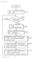
- Fig.2 is a flowchart illustrating a main routine for failure monitoring control that the sub CPU 2 performs on the main CPU 1.
- the sub CPU 2 sequentially executes a subroutine for an input/output monitoring process (step S1) and a subroutine for a watchdog monitoring process (step S2a).
- Fig.3 is a flowchart illustrating a main routine for failure monitoring control that the main CPU 1 performs on the sub CPU 2.
- the main CPU 1 executes a subroutine for a watchdog monitoring process (step S2b).
- step S1 we will describe the subroutine for an input/output monitoring process (step S1) performed in the sub CPU 2.
- the sub CPU 2 monitors the inputs/outputs to and from the main CPU 1
- the sub CPU 2 performs the same operations as those performed in the main CPU 1 for the steering assistance control, and compares the results with the results produced by the main CPU 1 for the steering assistance control, the result of the comparison being used for the detection of abnormality in the main CPU 1.
- Parameters used for the comparison include the current value for driving the motor 8, the rotating direction of the motor 8, and so on. Of these parameters, the current value for driving the motor 8 is taken as an example to explain the input/output monitoring process.
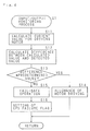
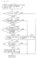
- Fig.4 is a flowchart illustrating the processing contents of the input/output monitoring subroutine (step S1) executed in the sub CPU 2.
- step S11 the same operation as in the main CPU 1 is performed to calculate the current value for driving the motor 8 (step S11), and then, the difference between the calculated current value and the supplied current detection value for driving the motor 8 is obtained (step S12).
- step S13 it is determined whether the difference is not greater than a predetermined value. If it is determined that the difference is not greater than the predetermined value, then it is decided that the main CPU 1 is operating normally, and the logic signals to be given to the first AND gate 12 and second AND gate 13 are all set at a high level to enable the driving of the motor 8 (step S14).
- step S15 if it is determined that the difference is greater than the predetermined value, it is then decided that abnormality has occurred in the operation of the main CPU 1, and the logic signals to be given to the first AND gate 12 and second AND gate 13 are all set at a low level to initiate a fail-safe operation to disable the driving of the motor 8 (step S15), a CPU failure flag is set to indicate that a failure has occurred in the CPU under monitor (step S16), and then, the process returns to the main routine.
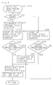
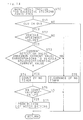
- Fig.5 is a flowchart illustrating the processing contents of the watchdog monitoring processing subroutine executed in the main CPU 1 (step S2b) as well as in the sub CPU 2 (step S2a).
- step S21 it is determined whether a pulse edge (the leading or trailing edge of a pulse) is detected in the watchdog pulse signal (step S21); if it is determined that a pulse edge is detected in the watchdog pulse signal, then the count value of a second cycle counter is cleared (step S22), and a first cycle counter is activated to count the cycle of the edge appearing in the watchdog pulse signal (step S23).
- a pulse edge the leading or trailing edge of a pulse
- step S24 it is determined whether the count value of the first cycle counter is not smaller than a predetermined value (step S24). If the count value is determined to be not smaller than the prescribed value in step S24, it means that the frequency of the watchdog pulse signal is at a proper value, and therefore, it is decided that the CPU that is generating the watchdog pulse signal is in a normal operating state. The count value of the first cycle counter is then cleared (step S25), and the process returns to the main routine.
- step S28 if the count value is determined to be smaller than the predetermined value, it means that the frequency of the watchdog pulse signal is higher than the proper value, and therefore, it is decided that the CPU that is generating the watchdog pulse signal is in an abnormal state. The process then proceeds to step S28 to initiate a fail-safe operation which will be described later.
- step S21 If, in step S21, it is determined that no edge is detected in the watchdog pulse signal, then the second cycle counter is activated to count the no-edge cycle of the watchdog pulse signal (step S26).
- step S27 it is determined whether the count value of the second cycle counter is not smaller than a predetermined value (step S27). If the count value is determined to be smaller than the predetermined value in step S27, it means that the frequency of the watchdog pulse signal is at a proper value, and therefore, it is decided that the CPU that is generating the watchdog pulse signal is in a normal operating state. The process then returns to the main routine.
- step S27 if the count value is determined to be not smaller than the predetermined value in step S27, it means that the frequency of the watchdog pulse signal is higher than the proper value, and therefore, it is decided that the CPU that is generating the watchdog pulse signal is in an abnormal state. The process then proceeds to step S28.
- step S28 a fail-safe operation is performed in which the logic signals to be given to the first AND gate 12 and second AND gate 13 are all set at a low level to disable the driving of the motor 8. After that, the process returns to the main routine.
- the logic signals to be given to the first AND gate 12 and second AND gate 13 are all set at a low level to disable the driving of the motor 8, but it will be appreciated that the fail-safe operation may be accomplished in other ways.
- a reset signal may be given to the abnormal CPU to reset the CPU.
- Another way to accomplish the fail-safe operation is to mount an electromagnetic clutch on the motor 8 and deenergise the electromagnetic clutch when a failure is detected in the operation of the CPU.
- a fail-safe relay may be provided on the power supply line in the motor driving circuit 7, the fail-safe relay being deactivated at the time of a CPU failure.
- the main CPU 1 and the sub CPU 2 mutually monitor the basic operation of each other for detection of failure on the basis of the watchdog pulse signal that one CPU sends to the other.
- the elimination of hardware such as the watchdog monitoring circuit required in the prior art contributes to a reduction in the production cost of the apparatus having a dual CPU configuration.
- the main CPU and the sub CPU mutually monitor each other for failure by monitoring the watchdog pulse signal that one CPU sends to the other CPU; in this control process, when a failure is detected in the main CPU or sub CPU, the CPU that has detected the failure of the other CPU performs a fail-safe operation, and when the abnormal CPU is restored to a normal operating state, the apparatus is released from the fail-safe operation.
- the fail-safe operation when activated, will not be deactivated until after stopping the vehicle, thereby stabilizing the system operating condition associated with the fail-safe operation.
- the configuration of the electric power steering apparatus of the second embodiment is fundamentally the same as that of the foregoing first embodiment (Fig.1), and therefore, the description of the configuration is omitted herein.
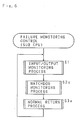
- Fig.6 is a flowchart illustrating a main routine for failure monitoring control that the sub CPU 2 performs on the main CPU 1.
- the sub CPU 2 sequentially executes a subroutine for an input/output monitoring process (step S1), a subroutine for a watchdog monitoring process (step S2c), and a subroutine for a normal return process (step S3a).
- Fig.7 is a flowchart illustrating a main routine for failure monitoring control that the main CPU 1 performs on the sub CPU 2.
- the main CPU 1 sequentially executes a subroutine for a watchdog monitoring process (step S2d) and a subroutine for a normal return process (step S3b).
- step S1 The subroutine for an input/output monitoring control (step S1) in the sub CPU 2 is the same as the subroutine for an input/output monitoring control (Fig.4) in the sub CPU 2 in the foregoing first embodiment, and the description thereof is therefore omitted hereinafter.
- Fig.8 is a flowchart illustrating the processing contents of the watchdog monitoring processing subroutine executed in the main CPU 1 (step S2d) as well as in the sub CPU 2 (step S2c).
- the watchdog monitoring processing subroutine in the second embodiment is essentially the same as the watchdog monitoring processing subroutine (steps S2a, S2b) in the first embodiment. Therefore, corresponding steps are designated by the same numbers as those in Fig.5, and description thereof is omitted herein.
- a CPU failure flag is set to indicate that a failure has occurred in the CPU under monitor (step S29), and then, the process returns to the main routine.
- Fig.9 is a flowchart illustrating the processing contents of the normal return processing subroutine executed in the main CPU 1 (step S3b) as well as in the sub CPU 2 (step S3a).
- step S31 it is determined whether the CPU failure flag is set or not (step S31). If it is determined in step S31 that the CPU failure flag is not set, the process returns to the main routine. On the other hand, if it is determined in step S31 that the CPU failure flag is set, then it is determined whether the detected vehicle speed is at zero or not (step S32).
- step S32 If it is determined in step S32 that the vehicle speed is not at zero (indicating that the vehicle is in motion), the process returns to the main routine. On the other hand, if it is determined in step S32 that the vehicle speed is at zero (indicating that the vehicle is in a stopped state), then the CPU failure flag is reset (step S33) and the fail-safe operation is terminated (step S34), after which the process returns to the main routine.
- the fail-safe operation may be accomplished either by disabling the driving of the motor 8, by resetting the abnormal CPU, or by deactivating a fail-safe relay at the time of a CPU failure.
- a fail-safe operation when a failure has occurred in the CPU under monitor, a fail-safe operation is first performed to disable the steering assistance, and when the CPU under monitor is restored thereafter to a normal operating state, the fail-safe operation is deactivated to release the steering assistance from the disabled state. It should be noted, however, that the fail-safe operation can only be deactivated after detecting the stopped state of the vehicle, to prevent the activation and deactivation of the steering assisting operation from being repeated during the traveling of the vehicle, thus ensuring stable travelling conditions of the vehicle.
- the steering assistance once disabled can be released from the disabled state only when the vehicle speed is at zero, so that the steering assisting operation once disabled as a result of a failure of the CPU under monitor will not be restarted during the travelling of the vehicle.
- This prevents unstable travelling conditions caused by repeatedly activating and deactivating the steering assisting operation with the CPU under monitor failing and then being restored to a normal operating state, and thus serves to stabilize the system operation associated with the fail-safe operation.
- the main CPU performs an operation to obtain the value of a motor driving current from the detected steering torque and vehicle speed, and thereby controls the steering assisting force of the motor.
- the sub CPU performs the same operation as in the main CPU and compares the operation result with that of the main CPU to monitor the inputs/outputs to and from the main CPU for detection of abnormality in the main CPU.
- the sub CPU performs a fail-safe control, involving the stopping of the motor and so on, to secure the system safety.
- the dangerous steering assisting situation that may result from malfunctioning of the CPU for controlling the motor is represented by the following three states: the first state in which steering assisting force is exerted in a steering situation where no steering assisting force is needed; the second state in which steering assisting force is exerted in a direction opposite to the steering direction of the steering wheel; and the third state in which excessive steering assisting force is exerted. Therefore, in the failure monitoring of the main CPU responsible for controlling the motor, it is only necessary to monitor the inputs and outputs to and from the main CPU for the occurrence of any of the above three states.
- control information on the driving current value indicates a value which does not drop below a predetermined value while the detected steering torque is inside a dead zone
- the sub CPU determines the situation as a failure of the main CPU and thus detects the above first state
- control information on the rotating direction of the motor indicates a direction opposite to the direction of the detected steering torque while the detected steering torque is outside the dead zone
- the sub CPU determines the situation as a failure of the main CPU and thus detects the second state
- the driving current is greater than a predetermined value
- the sub CPU determines the situation as a failure of the main CPU and thus detects the third state.
- Fig.10 is a block diagram illustrating the configuration of an electric power steering apparatus according to the third embodiment of the invention.
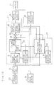
- the reference numeral 21 designates a main CPU responsible for steering assistance control, and the operating state of the main CPU 21 is monitored by a sub CPU 22.
- the steering torque applied at the steering wheel is detected by a torque sensor 23 and amplified through an amplifier 24.
- the amplified signal, a torque detection signal T is given to a phase compensating section 31 and a differentiating section 32 in the main CPU 21 as well as to a differentiating section 41 and a fail-safe monitoring section 42 in the sub CPU 22.
- a vehicle speed detection signal V which is outputted from a vehicle speed sensor 25 that detects the travelling speed of the vehicle, is given to the differentiating section 32 and a function generating section 33 in the main CPU 21 as well as to the differentiating section 41 and the fail-safe monitoring section 42 in the sub CPU 22.
- a current detection circuit 28 detects a driving current for driving a motor 27 for steering assistance and outputs a current detection signal Is which is given to a subtracter 35 in the main CPU 21 as well as to the fail-safe monitoring section 42 in the sub CPU 22. Furthermore, a motor driving direction signal representing the driving direction of the motor 27 is given from a motor driving circuit 26 to the fail-safe monitoring section 42 in the sub CPU 22.
- the torque detection signal T, vehicle speed detection signal V, and current detection signal Is, supplied to the main and sub CPUs 21 and 22, are analog-to-digital converted by A/D converters (not shown) respectively provided in the main and sub CPUs 21 and 22.
- the phase compensating section 31 advances the phase of the torque detection signal T and supplies the torque detection signal T representing a steering torque T to the function generating section 33 which outputs a target current value I, a tentative target value for the motor current.
- a function is variably set according to the vehicle speed V (where V1 ⁇ V2 ⁇ V3 ⁇ V4 ...) represented as the vehicle speed detection signal V that is given from the vehicle speed sensor 25, the function being such that, as shown in the figure, in the ranges of the steering torque T outside a predetermined dead zone, the target current value I increases proportionately with increasing steering torque T, the target current value I being saturated when the steering torque T exceeds a predetermined value.
- the function is set so that as the vehicle speed V1, V2, V3, V4 ... increases, the ratio of the target current value I to the steering torque T decreases, so does the saturation value of the target current I.
- the function generating section 33 determines the target current value I based on the steering torque T and supplies the target current value I to an adder 34.
- the differentiating section 32 differentiates the torque detection signal T, multiplies the result by a differential constant that is determined according to the vehicle speed detection signal V, and supplies a differential current value Id1, the resulting product, to the adder 34.
- the adder 34 adds the target current value I supplied from the function generating section 33 to the differential current value Id1 supplied from the differentiating section 32, and supplies the resulting sum to the subtracter 35.
- the subtracter 35 subtracts the current detection value Is, represented as the current detection signal Is detected by the current detection circuit 28, from the sum produced by the adder 34, and supplies the resulting difference to a target voltage calculating section 36.
- the target voltage calculating section 36 performs a PID operation on the thus supplied difference, and supplies a PWM signal corresponding to the result of the operation to the motor driving circuit 26 for driving the motor 27.
- the motor driving circuit 26 drives the motor 27 on the basis of the PWM signal.
- the differentiating section 41 differentiates the torque detection signal T, multiplies the result by a differential constant that is determined according to the vehicle speed detection signal V, and supplies a differential current value Id2, the resulting product, to the fail-safe monitoring section 42.
- the fail-safe monitoring section 42 Based on the steering torque T, vehicle speed V, differential current value Id2, current detection value Is, and motor driving direction signal, the fail-safe monitoring section 42 performs processing pertaining to the monitoring of control operations in the main CPU 21 as will be described later.
- a motor drive disabling signal to disable the driving of the motor 27 is given to the motor driving circuit 26.
- Fig.11 is a flowchart illustrating the processing contents of the main routine executed in the sub CPU 22.
- step S10 When the program is started, the memory, register, timer, etc. in the sub CPU 22 are first initialized (step S10). Then, waiting for the timer that sets the operation cycle to count a set value (e.g., 1msec) (step S20), the input signal (torque detection signal T) is analog-to-digital converted (step S30), and the torque detection signal T is differentiated by the differentiating section 41 (step S40).
- a set value e.g., 1msec
- the fail-safe monitoring section 42 sequentially executes a subroutine for monitoring the steering wheel rotation (step S50), a subroutine for monitoring for reverse steering assistance (step S60), and a subroutine for monitoring for excessive steering assistance (step S70).
- Fig.12 is a flowchart illustrating the processing contents of the subroutine for monitoring the steering wheel rotation (step S50).
- step S51 it is determined whether the clutch (not shown) for transmitting the rotational force of the motor 27 to the steering mechanism is engaged or not (step S51). If it is determined in step S51 that the clutch is not engaged, the process returns to the main routine. On the other hand, if it is determined in step S51 that the clutch is engaged, then it is determined whether the steering torque T is inside the dead zone as set in the function generating section 33 (step S52).
- step S52 If it is determined in step S52 that the steering torque T is not inside the dead zone, the count value of the NG counter that counts the time for execution of the fail-safe operation (to disable the driving of the motor 27) is cleared (step S54), and then, the process returns to the main routine. On the other hand, if it is determined in step S52 that the steering torque T is inside the dead zone, then it is determined whether the current detection value Is is greater than the differential current value Id2 (step S53).
- step S53 If it is determined in step S53 that the current detection value Is is not greater than the differential current value Id2, the count value of the NG timer is cleared (step S54), and the process returns to the main routine.
- step S53 determines whether the current detection value Is is greater than the differential current value Id2
- the counting by the NG timer is done (step S55).
- step S56 it is determined whether the count value of the NG timer has reached a prescribed set value (e.g. 20msec) (step S56).
- step S56 If it is determined in step S56 that the count value of the NG timer is smaller than the set value, the process returns to the main routine. On the other hand, if it is determined in step S56 that the count value of the NG timer has reached the set value, a motor drive disabling signal is given to the motor driving circuit 26 to disable the driving of the motor 27 (step S57), and the process returns to the main routine.
- Fig.13 is a flowchart illustrating the processing contents of the subroutine for monitoring for reverse steering assistance (step S60).
- step S61 it is determined whether the clutch (not shown) for transmitting the rotational force of the motor 27 to the steering mechanism is engaged or not (step S61). If it is determined in step S61 that the clutch is not engaged, the process returns to the main routine. On the other hand, if it is determined in step S61 that the clutch is engaged, then it is determined whether the steering torque T is inside the dead zone as set in the function generating section 33 (step S62).
- step S62 If it is determined in step S62 that the steering torque T is inside the dead zone, the count value of the NG counter that counts the time for execution of the fail-safe operation (to disable the driving of the motor 27) is cleared (step S67), and then, the process returns to the main routine. On the other hand, if it is determined in step S62 that the steering torque T is not inside the dead zone, then it is determined whether the direction of the steering torque T is in a right turn (step S63).
- step S63 If it is determined in step S63 that the direction of the steering torque T is in a right turn, then it is determined whether the motor driving direction designated by the motor driving direction signal is in a left turn (step S64). On the other hand, if it is determined in step S63 that the direction of the steering torque T is not in a right turn (but in a left turn), then it is determined whether the motor driving direction designated by the motor driving direction signal is in a right turn (step S65).
- step S64 If it is determined in step S64 that the motor driving direction is in a left turn (the steering assistance direction is opposite to the steering direction), the counting by the NG timer is done (step S66). On the other hand, if it is determined in step S64 that the motor driving direction is not in a left turn (but in a right turn, which means that the steering assistance direction matches the steering direction), the count value of the NG timer is cleared (step S67), and the process returns to the main routine.
- step S65 If it is determined in step S65 that the motor driving direction is in a right turn (the steering assistance direction is opposite to the steering direction), the counting by the NG timer is done (step S66). On the other hand, if it is determined in step S65 that the motor driving direction is not in a right turn (but in a left turn, which means that the steering assistance direction matches the steering direction), the count value of the NG timer is cleared (step S67), and the process returns to the main routine.
- step S66 it is determined whether the count value of the NG timer has reached a prescribed set value (e.g. 20msec) (step S68).
- a prescribed set value e.g. 20msec
- step S68 If it is determined in step S68 that the count value of the NG timer is smaller than the set value, the process returns to the main routine. On the other hand, if it is determined in step S68 that the count value of the NG timer has reached the set value, a motor drive disabling signal is given to the motor driving circuit 26 to disable the driving of the motor 27 (step S69), and then, the process returns to the main routine.
- Fig.14 is a flowchart illustrating the processing contents of the subroutine for monitoring for excessive steering assistance (step S70).
- step S71 it is determined whether the clutch (not shown) for transmitting the rotational force of the motor 27 to the steering mechanism is engaged or not (step S71). If it is determined in step S71 that the clutch is not engaged, the process returns to the main routine. On the other hand, if it is determined in step S71 that the clutch is engaged, then it is determined whether the vehicle speed V is greater than a set value (e.g. 40km/h) (step S72).
- a set value e.g. 40km/h
- step S72 If it is determined in step S72 that the vehicle speed V is smaller than the set value, the count value of the NG counter that counts the time for execution of the fail-safe operation (to disable the driving of the motor 27) is cleared (step S75), and then, the process returns to the main routine.
- step S72 If it is determined in step S72 that the car speed V is not smaller than the set value, then it is determined whether the current detection value Is is greater than the sum of the differential current value Id2 and the maximum value of the target current value I determined in the function generating section 33 according to the vehicle speed V (hereinafter referred to as the maximum current value corresponding to vehicle speed) (step S73).
- step S73 If it is determined in step S73 that the current detection value Is is not greater than the sum of the differential current value Id2 and the maximum current value corresponding to vehicle speed, the count value of the NG timer is cleared (step S75), and the process returns to the main routine.
- step S73 if it is determined in step S73 that the current detection value Is is greater than the sum of the differential current value Id2 and the maximum current value corresponding to vehicle speed, the counting by the NG timer is done (step S74). Next, it is determined whether the count value of the NG timer has reached a prescribed set value (e.g. 20msec) (step S76).
- a prescribed set value e.g. 20msec
- step S76 If it is determined in step S76 that the count value of the NG timer is smaller than the set value, the process returns to the main routine. On the other hand, if it is determined in step S76 that the count value of the NG timer has reached the set value, a motor drive disabling signal is given to the motor driving circuit 26 to disable the driving of the motor 27 (step S77), and then, the process returns to the main routine.
- the fail-safe monitoring section 42 is capable of detecting malfunctioning of the main CPU 21 just by performing the three types of failure monitoring that can be accomplished by simple arithmetic operations involving comparison as described above, the sub CPU 22 is not required to have a processing capacity equivalent to that of the main CPU 21. This contributes to a reduction in the production cost of the electric power steering apparatus.
Description
- The present invention relates to an electric power steering apparatus for assisting the force required to turn the steering wheel of a vehicle.
- US-A-4,869,334 describes an electric power steering apparatus which uses a vehicle speed sensor to measure the travelling speed of the vehicle and a torque sensor to measure the steering torque applied at the steering wheel. In the electric power steering apparatus of this type, when the steering torque measured exceeds a predetermined dead zone, a steering assisting motor is driven by a driving current of the magnitude determined according to the measured steering torque and the measured vehicle speed, and the rotational force of the motor is used to provide power to assist the force required to steer the vehicle, thereby providing a comfortable steering feel to the driver. The steering assistance is controlled by a controller (hereinafter called the CPU). One such electric power steering apparatus employs a dual CPU configuration to assure the system safety against malfunctions, such as runaway, of the CPU.
- The electric power steering apparatus with a dual CPU configuration has a main CPU for controlling the steering assisting force and a sub CPU for detecting failure of the main CPU by monitoring the inputs and outputs to and from the main CPU so that, upon detection of failure of the main CPU, the sub CPU initiates a fail-safe control, involving the stopping of the motor and so on, to secure the system safety.
- In the dual CPU system, it is necessary to separately monitor the basic operation of each individual CPU. To achieve this, each of the main and sub CPUs is connected to a separate watchdog monitoring circuit which measures the frequency of watchdog pulses generated at a fixed repetition rate from the CPU connected to it and compares the measured frequency with a reference value to detect failure in the CPU operation. When any abnormality in the main or sub CPU operation is detected by the associated watchdog monitoring circuit, the fail-safe control is performed.
- However, the above electric power steering apparatus having separate watchdog monitoring circuits for the main and sub CPUs has the problem of increasing the production cost because of the provision of the two watchdog monitoring circuits in the form of hardware in addition to the main and sub CPUs.
- It is the object of the invention to provide an electric power steering apparatus having low production costs.
- This problem is solved, according to the invention, with the features of
claim 1. - It is an advantage that, when an abnormal CPU is restored to a normal operating state, the apparatus is released from a fail-safe control only after the vehicle is stopped, thereby stabilizing the system operating condition associated with the fail-safe control operation.
- It is a further advantage of the invention that the electric power steering apparatus allows the use of a sub CPU having a lower processing capacity than that of the main CPU by simplifying the operation processing performed by the sub CPU, thereby achieving a reduction in the production cost of the apparatus.
- Generally, in an electric power steering apparatus, the dangerous steering assisting situation that may result from malfunctioning of the CPU for controlling the motor is represented by the following three states: the first state in which steering assisting force is exerted in a steering situation where no steering assisting force is needed; the second state in which steering assisting force is exerted in a direction opposite to the steering direction of the steering wheel; and the third state in which excessive steering assisting force is exerted.
- In the electric power steering apparatus of the invention, the sub CPU monitors the main CPU for the occurrence of any of these three states to detect abnormality in the operation of the main CPU. Therefore, the sub CPU is only required to perform simple arithmetic operations, and, accordingly, the configuration of the sub CPU can be simplified.
- When abnormality is detected in the CPU, the abnormal CPU is reset to isolate it from the control relating to the steering assistance, thus preventing dangerous steering assisting action that may result from malfunctioning of the CPU.
- In one preferred mode of the electric power steering apparatus of the invention, even if the abnormal CPU is restored to a normal operating state, the steering assistance, once disabled, can be enabled only when the vehicle speed is at zero; that is, once the steering assistance is disabled as a result of detection of failure in the CPU under monitor, the steering assistance will not be restarted while the vehicle is in motion. This serves to prevent unstable travelling conditions which would be caused by repetitive activation and deactivation of the steering assistance.
- The above and further objects and features of the invention will more fully be apparent from the following detailed description with accompanying drawings in which the first and second embodiments do not belong to the invention. In the drawings
- Fig. 1 is a block diagram showing the configuration of an electric power steering apparatus according to a first and a second embodiment,
- Fig. 2 is a flowchart illustrating a main routine for a failure monitoring control that the sub CPU performs on the main CPU according to the first embodiment;
- Fig.3 is a flowchart illustrating a main routine for a failure monitoring control that the main CPU performs on the sub CPU according to the first embodiments of the invention;
- Fig.4 is a flowchart illustrating a subroutine for an input/output monitoring process performed in the sub CPU according to the first and second embodiments;
- Fig.5 is a flowchart illustrating a subroutine for a watchdog monitoring process performed in the main and sub CPUs according to the first embodiment;
- Fig.6 is a flowchart illustrating a main routine for a failure monitoring control that the sub CPU performs on the main CPU according to the second embodiment;
- Fig.7 is a flowchart illustrating a main routine for a failure monitoring control that the main CPU performs on the sub CPU according to the second embodiment;
- Fig.8 is a flowchart illustrating a subroutine for a watchdog monitoring process performed in the main and sub CPUs according to the second embodiment;
- Fig.9 is a flowchart illustrating a subroutine for a normal return process performed in the main and sub CPUs according to the second embodiment;
- Fig. 10 is a block diagram showing the configuration of an electric power steering apparatus according to a third embodiment illustrating the invention;
- Fig. 11 is a flowchart illustrating a main routine executed in the sub CPU in the third embodiment;
- Fig. 12 is a flowchart illustrating a subroutine for a monitoring process for steering wheel rotation in Fig. 11;
- Fig. 13 is a flowchart illustrating a subroutine for a monitoring process for reverse steering assistance in Fig. 11; and
- Fig. 14 is a flowchart illustrating a subroutine for a monitoring process for excessive steering assistance in Fig. 11.
- The invention will now be described in detail with reference to the accompanying drawings.
- Fig. 1 is a block diagram showing the configuration of an electric power steering apparatus according to the first embodiment. The
reference numeral 1 designates a main CPU responsible for a steering assistance control, and the operating state of themain CPU 1 is monitored by a sub CPU 2. Themain CPU 1 sends a watchdog pulse signal to the sub CPU 2, based on which signal the sub CPU 2 monitors the basic operating state of themain CPU 1. On the other hand, the sub CPU 2 sends a watchdog pulse signal to themain CPU 1, based on which signal themain CPU 1 monitors the basic operating state of the sub CPU 2. - Other signals supplied to the
main CPU 1 are: a torque detection signal representing a steering torque applied at the steering wheel, the steering torque being detected by atorque sensor 3 and amplified through anamplifier 11; an engine speed detection signal from anengine speed sensor 4 which detects the number of engine revolutions; and a vehicle speed detection signal from a vehicle speed sensor 5 which detects the traveling speed of the vehicle. - The torque detection signal amplified by the
amplifier 11 and representing the result of detection by thetorque sensor 3 and the vehicle speed detection signal from the car speed sensor 5 are also supplied to the sub CPU 2. - Based on the thus supplied torque detection signal and vehicle speed detection signal, the
main CPU 1 performs prescribed operations to obtain a driving current to drive a motor 8 for the steering assistance as well as the rotating direction of the motor 8. Themain CPU 1 then sends a PWM driving signal, corresponding to the driving current, to a motor driving circuit 7. When the obtained rotating direction of the motor 8 is clockwise, themain CPU 1 applies a high logic signal to afirst AND gate 12 which then supplies a clockwise rotation signal to the motor driving circuit 7 to drive the motor 8 in clockwise direction. On the other hand, when the obtained rotating direction of the motor 8 is counterclockwise, themain CPU 1 applies a high logic signal to asecond AND gate 13 which then supplies a counterclockwise rotation signal to the motor driving circuit 7 to drive the motor 8 in counterclockwise direction. Besides the control operations as described above, themain CPU 1 performs a control to monitor the basic operation of the sub CPU 2 for detection of failure, as will be described later, based on the watchdog pulse signal supplied from the sub CPU 2. - Based on the supplied torque detection signal and vehicle speed detection signal, the sub CPU 2 performs the same operations as those performed in the
main CPU 1, to obtain a driving current to drive the motor 8 as well as the rotating direction of the motor 8, and monitors the control operations of themain CPU 1 for detection of failure, as will be described later. At the same time, the sub CPU 2 performs a control to monitor the basic operation of themain CPU 1 for detection of failure, based on the watchdog pulse signal supplied from themain CPU 1, and supplies logic signals to thefirst AND gate 12 and second ANDgate 13. - When the logic signals inputted from the
main CPU 1 and sub CPU 2 are both at a high level, the first ANDgate 12 outputs a high clockwise rotation signal which is given to the motor driving circuit 7. On the other hand, when the logic signals inputted from themain CPU 1 and sub CPU 2 are both at a high level, the second ANDgate 13 outputs a high counterclockwise rotation signal which is given to the motor driving circuit 7. - The motor driving circuit 7 determines the rotating direction of the motor 8 based on the logic states of the clockwise and counterclockwise rotation signals, and drives the motor 8 based on the PWM driving signal supplied from the
main CPU 1. When the logic signals supplied from the first ANDgate 12 and second ANDgate 13 are both low, the motor driving circuit 7 disables the driving of the motor 8. The current for driving the motor 8 is detected by a current detectingresistor 10, and the detected result is given to themain CPU 1, as well as to the sub CPU 2, via an amplifier 9. - Next, we will describe the failure monitoring control operations performed by the
main CPU 1 and sub CPU 2 in the electric power steering apparatus of the above configuration. Fig.2 is a flowchart illustrating a main routine for failure monitoring control that the sub CPU 2 performs on themain CPU 1. The sub CPU 2 sequentially executes a subroutine for an input/output monitoring process (step S1) and a subroutine for a watchdog monitoring process (step S2a). Fig.3 is a flowchart illustrating a main routine for failure monitoring control that themain CPU 1 performs on the sub CPU 2. Themain CPU 1 executes a subroutine for a watchdog monitoring process (step S2b). - First, we will describe the subroutine for an input/output monitoring process (step S1) performed in the sub CPU 2. In the input/output monitoring process in which the sub CPU 2 monitors the inputs/outputs to and from the
main CPU 1, the sub CPU 2 performs the same operations as those performed in themain CPU 1 for the steering assistance control, and compares the results with the results produced by themain CPU 1 for the steering assistance control, the result of the comparison being used for the detection of abnormality in themain CPU 1. Parameters used for the comparison include the current value for driving the motor 8, the rotating direction of the motor 8, and so on. Of these parameters, the current value for driving the motor 8 is taken as an example to explain the input/output monitoring process. - Fig.4 is a flowchart illustrating the processing contents of the input/output monitoring subroutine (step S1) executed in the sub CPU 2. First, the same operation as in the
main CPU 1 is performed to calculate the current value for driving the motor 8 (step S11), and then, the difference between the calculated current value and the supplied current detection value for driving the motor 8 is obtained (step S12). - Next, it is determined whether the difference is not greater than a predetermined value (step S13). If it is determined that the difference is not greater than the predetermined value, then it is decided that the
main CPU 1 is operating normally, and the logic signals to be given to the first ANDgate 12 and second ANDgate 13 are all set at a high level to enable the driving of the motor 8 (step S14). - On the other hand, if it is determined that the difference is greater than the predetermined value, it is then decided that abnormality has occurred in the operation of the
main CPU 1, and the logic signals to be given to the first ANDgate 12 and second ANDgate 13 are all set at a low level to initiate a fail-safe operation to disable the driving of the motor 8 (step S15), a CPU failure flag is set to indicate that a failure has occurred in the CPU under monitor (step S16), and then, the process returns to the main routine. - Next, we will describe the watchdog monitoring process that the
main CPU 1 performs on the sub CPU 2 and the equivalent process that the sub CPU 2 performs on themain CPU 1. The contents of the watchdog monitoring process are the same between themain CPU 1 and the sub CPU 2. - Fig.5 is a flowchart illustrating the processing contents of the watchdog monitoring processing subroutine executed in the main CPU 1 (step S2b) as well as in the sub CPU 2 (step S2a).
- First, it is determined whether a pulse edge (the leading or trailing edge of a pulse) is detected in the watchdog pulse signal (step S21); if it is determined that a pulse edge is detected in the watchdog pulse signal, then the count value of a second cycle counter is cleared (step S22), and a first cycle counter is activated to count the cycle of the edge appearing in the watchdog pulse signal (step S23).
- Next, it is determined whether the count value of the first cycle counter is not smaller than a predetermined value (step S24). If the count value is determined to be not smaller than the prescribed value in step S24, it means that the frequency of the watchdog pulse signal is at a proper value, and therefore, it is decided that the CPU that is generating the watchdog pulse signal is in a normal operating state. The count value of the first cycle counter is then cleared (step S25), and the process returns to the main routine.
- On the other hand, if the count value is determined to be smaller than the predetermined value, it means that the frequency of the watchdog pulse signal is higher than the proper value, and therefore, it is decided that the CPU that is generating the watchdog pulse signal is in an abnormal state. The process then proceeds to step S28 to initiate a fail-safe operation which will be described later.
- If, in step S21, it is determined that no edge is detected in the watchdog pulse signal, then the second cycle counter is activated to count the no-edge cycle of the watchdog pulse signal (step S26).
- Next, it is determined whether the count value of the second cycle counter is not smaller than a predetermined value (step S27). If the count value is determined to be smaller than the predetermined value in step S27, it means that the frequency of the watchdog pulse signal is at a proper value, and therefore, it is decided that the CPU that is generating the watchdog pulse signal is in a normal operating state. The process then returns to the main routine.
- On the other hand, if the count value is determined to be not smaller than the predetermined value in step S27, it means that the frequency of the watchdog pulse signal is higher than the proper value, and therefore, it is decided that the CPU that is generating the watchdog pulse signal is in an abnormal state. The process then proceeds to step S28.
- In step S28, a fail-safe operation is performed in which the logic signals to be given to the first AND
gate 12 and second ANDgate 13 are all set at a low level to disable the driving of the motor 8. After that, the process returns to the main routine. - In this embodiment, to accomplish the fail-safe operation, the logic signals to be given to the first AND
gate 12 and second ANDgate 13 are all set at a low level to disable the driving of the motor 8, but it will be appreciated that the fail-safe operation may be accomplished in other ways. For example, a reset signal may be given to the abnormal CPU to reset the CPU. Another way to accomplish the fail-safe operation is to mount an electromagnetic clutch on the motor 8 and deenergise the electromagnetic clutch when a failure is detected in the operation of the CPU. Alternatively, a fail-safe relay may be provided on the power supply line in the motor driving circuit 7, the fail-safe relay being deactivated at the time of a CPU failure. - In the electric power steering apparatus having the above control functions, the
main CPU 1 and the sub CPU 2 mutually monitor the basic operation of each other for detection of failure on the basis of the watchdog pulse signal that one CPU sends to the other. This eliminates the need for a separate watchdog monitoring circuit which, in the prior art, have had to be provided for each of themain CPU 1 and sub CPU 2. The elimination of hardware such as the watchdog monitoring circuit required in the prior art contributes to a reduction in the production cost of the apparatus having a dual CPU configuration. - Furthermore, when a failure is detected in one or other of the two CPUs, either the steering assistance is disabled or the abnormal CPU is reset. This serves to eliminate the possibility of dangerous steering assisting action that may result from a CPU failure, and thus assures the system safety.
- In the first embodiment described above, the main CPU and the sub CPU mutually monitor each other for failure by monitoring the watchdog pulse signal that one CPU sends to the other CPU; in this control process, when a failure is detected in the main CPU or sub CPU, the CPU that has detected the failure of the other CPU performs a fail-safe operation, and when the abnormal CPU is restored to a normal operating state, the apparatus is released from the fail-safe operation.
- However, if the failure/restoration cycle of one or other CPU is repeated, activating and deactivating the fail-safe operation in a repetitive manner while the vehicle is in motion, the operation of the system will become unstable, introducing instability in the traveling of the vehicle. Unstable operation of the system is particularly dangerous when the vehicle is traveling at high speed.
- In the second embodiment described hereinafter, when an abnormal CPU is restored to a normal state, the fail-safe operation, once activated, will not be deactivated until after stopping the vehicle, thereby stabilizing the system operating condition associated with the fail-safe operation.
- The configuration of the electric power steering apparatus of the second embodiment is fundamentally the same as that of the foregoing first embodiment (Fig.1), and therefore, the description of the configuration is omitted herein.
- The following description deals with the failure monitoring control operations performed by the
main CPU 1 and sub CPU 2 in the electric power steering apparatus of the second embodiment. Fig.6 is a flowchart illustrating a main routine for failure monitoring control that the sub CPU 2 performs on themain CPU 1. The sub CPU 2 sequentially executes a subroutine for an input/output monitoring process (step S1), a subroutine for a watchdog monitoring process (step S2c), and a subroutine for a normal return process (step S3a). Fig.7 is a flowchart illustrating a main routine for failure monitoring control that themain CPU 1 performs on the sub CPU 2. Themain CPU 1 sequentially executes a subroutine for a watchdog monitoring process (step S2d) and a subroutine for a normal return process (step S3b). - The subroutine for an input/output monitoring control (step S1) in the sub CPU 2 is the same as the subroutine for an input/output monitoring control (Fig.4) in the sub CPU 2 in the foregoing first embodiment, and the description thereof is therefore omitted hereinafter.
- Fig.8 is a flowchart illustrating the processing contents of the watchdog monitoring processing subroutine executed in the main CPU 1 (step S2d) as well as in the sub CPU 2 (step S2c). The watchdog monitoring processing subroutine in the second embodiment is essentially the same as the watchdog monitoring processing subroutine (steps S2a, S2b) in the first embodiment. Therefore, corresponding steps are designated by the same numbers as those in Fig.5, and description thereof is omitted herein. In the second embodiment, after performing the fail-safe operation in step S28, a CPU failure flag is set to indicate that a failure has occurred in the CPU under monitor (step S29), and then, the process returns to the main routine.
- Next, we will describe the normal return processing performed on the sub CPU 2 by the
main CPU 1 and the equivalent processing performed on themain CPU 1 by the sub CPU 2. The processing contents are the same between themain CPU 1 and the sub CPU 2. - Fig.9 is a flowchart illustrating the processing contents of the normal return processing subroutine executed in the main CPU 1 (step S3b) as well as in the sub CPU 2 (step S3a).
- First, it is determined whether the CPU failure flag is set or not (step S31). If it is determined in step S31 that the CPU failure flag is not set, the process returns to the main routine. On the other hand, if it is determined in step S31 that the CPU failure flag is set, then it is determined whether the detected vehicle speed is at zero or not (step S32).
- If it is determined in step S32 that the vehicle speed is not at zero (indicating that the vehicle is in motion), the process returns to the main routine. On the other hand, if it is determined in step S32 that the vehicle speed is at zero (indicating that the vehicle is in a stopped state), then the CPU failure flag is reset (step S33) and the fail-safe operation is terminated (step S34), after which the process returns to the main routine.
- In the second embodiment, as well as in the first embodiment, the fail-safe operation may be accomplished either by disabling the driving of the motor 8, by resetting the abnormal CPU, or by deactivating a fail-safe relay at the time of a CPU failure.
- In the above failure monitoring control, when a failure has occurred in the CPU under monitor, a fail-safe operation is first performed to disable the steering assistance, and when the CPU under monitor is restored thereafter to a normal operating state, the fail-safe operation is deactivated to release the steering assistance from the disabled state. It should be noted, however, that the fail-safe operation can only be deactivated after detecting the stopped state of the vehicle, to prevent the activation and deactivation of the steering assisting operation from being repeated during the traveling of the vehicle, thus ensuring stable travelling conditions of the vehicle.
- As described above, in the electric power steering apparatus of the second embodiment, even when the abnormal CPU is restored to a normal operating state, the steering assistance once disabled, can be released from the disabled state only when the vehicle speed is at zero, so that the steering assisting operation once disabled as a result of a failure of the CPU under monitor will not be restarted during the travelling of the vehicle. This prevents unstable travelling conditions caused by repeatedly activating and deactivating the steering assisting operation with the CPU under monitor failing and then being restored to a normal operating state, and thus serves to stabilize the system operation associated with the fail-safe operation.
- Generally, in an electric power steering apparatus having a dual CPU configuration, the main CPU performs an operation to obtain the value of a motor driving current from the detected steering torque and vehicle speed, and thereby controls the steering assisting force of the motor. In the meantime, the sub CPU performs the same operation as in the main CPU and compares the operation result with that of the main CPU to monitor the inputs/outputs to and from the main CPU for detection of abnormality in the main CPU. When abnormality in the operation of the main CPU is detected by the sub CPU, the sub CPU performs a fail-safe control, involving the stopping of the motor and so on, to secure the system safety.
- However, such an electric power steering apparatus equipped with a dual CPU configuration has the problem of increasing the production cost of the apparatus since the sub CPU responsible for monitoring is required to have a processing capacity equivalent to that of the main CPU. The third embodiment hereinafter described allows the use of a monitoring sub CPU having a lower processing capacity than that of the main CPU by simplifying the operation processing to be performed in the sub CPU.
- Generally, in an electric power steering apparatus, the dangerous steering assisting situation that may result from malfunctioning of the CPU for controlling the motor is represented by the following three states: the first state in which steering assisting force is exerted in a steering situation where no steering assisting force is needed; the second state in which steering assisting force is exerted in a direction opposite to the steering direction of the steering wheel; and the third state in which excessive steering assisting force is exerted. Therefore, in the failure monitoring of the main CPU responsible for controlling the motor, it is only necessary to monitor the inputs and outputs to and from the main CPU for the occurrence of any of the above three states. More specifically, when control information on the driving current value indicates a value which does not drop below a predetermined value while the detected steering torque is inside a dead zone, the sub CPU determines the situation as a failure of the main CPU and thus detects the above first state; when control information on the rotating direction of the motor indicates a direction opposite to the direction of the detected steering torque while the detected steering torque is outside the dead zone, the sub CPU determines the situation as a failure of the main CPU and thus detects the second state; and when the driving current is greater than a predetermined value, the sub CPU determines the situation as a failure of the main CPU and thus detects the third state. These monitoring operations by the sub CPU are performed by comparing the information on the inputs and outputs to and from the main CPU, and therefore, can be accomplished by simple operation processing.
- Fig.10 is a block diagram illustrating the configuration of an electric power steering apparatus according to the third embodiment of the invention. The
reference numeral 21 designates a main CPU responsible for steering assistance control, and the operating state of themain CPU 21 is monitored by asub CPU 22. - The steering torque applied at the steering wheel is detected by a
torque sensor 23 and amplified through anamplifier 24. The amplified signal, a torque detection signal T, is given to aphase compensating section 31 and a differentiatingsection 32 in themain CPU 21 as well as to a differentiatingsection 41 and a fail-safe monitoring section 42 in thesub CPU 22. On the other hand, a vehicle speed detection signal V, which is outputted from avehicle speed sensor 25 that detects the travelling speed of the vehicle, is given to the differentiatingsection 32 and afunction generating section 33 in themain CPU 21 as well as to the differentiatingsection 41 and the fail-safe monitoring section 42 in thesub CPU 22. - A
current detection circuit 28 detects a driving current for driving amotor 27 for steering assistance and outputs a current detection signal Is which is given to asubtracter 35 in themain CPU 21 as well as to the fail-safe monitoring section 42 in thesub CPU 22. Furthermore, a motor driving direction signal representing the driving direction of themotor 27 is given from amotor driving circuit 26 to the fail-safe monitoring section 42 in thesub CPU 22. The torque detection signal T, vehicle speed detection signal V, and current detection signal Is, supplied to the main andsub CPUs sub CPUs - In the
main CPU 21, thephase compensating section 31 advances the phase of the torque detection signal T and supplies the torque detection signal T representing a steering torque T to thefunction generating section 33 which outputs a target current value I, a tentative target value for the motor current. - In the
function generating section 33, a function is variably set according to the vehicle speed V (where V1 < V2 < V3 < V4 ...) represented as the vehicle speed detection signal V that is given from thevehicle speed sensor 25, the function being such that, as shown in the figure, in the ranges of the steering torque T outside a predetermined dead zone, the target current value I increases proportionately with increasing steering torque T, the target current value I being saturated when the steering torque T exceeds a predetermined value. The function is set so that as the vehicle speed V1, V2, V3, V4 ... increases, the ratio of the target current value I to the steering torque T decreases, so does the saturation value of the target current I. Using this function, thefunction generating section 33 determines the target current value I based on the steering torque T and supplies the target current value I to anadder 34. - On the other hand, the differentiating
section 32 differentiates the torque detection signal T, multiplies the result by a differential constant that is determined according to the vehicle speed detection signal V, and supplies a differential current value Id1, the resulting product, to theadder 34. Theadder 34 adds the target current value I supplied from thefunction generating section 33 to the differential current value Id1 supplied from the differentiatingsection 32, and supplies the resulting sum to thesubtracter 35. - The
subtracter 35 subtracts the current detection value Is, represented as the current detection signal Is detected by thecurrent detection circuit 28, from the sum produced by theadder 34, and supplies the resulting difference to a targetvoltage calculating section 36. The targetvoltage calculating section 36 performs a PID operation on the thus supplied difference, and supplies a PWM signal corresponding to the result of the operation to themotor driving circuit 26 for driving themotor 27. Themotor driving circuit 26 drives themotor 27 on the basis of the PWM signal. - In the
sub CPU 22, the differentiatingsection 41 differentiates the torque detection signal T, multiplies the result by a differential constant that is determined according to the vehicle speed detection signal V, and supplies a differential current value Id2, the resulting product, to the fail-safe monitoring section 42. Based on the steering torque T, vehicle speed V, differential current value Id2, current detection value Is, and motor driving direction signal, the fail-safe monitoring section 42 performs processing pertaining to the monitoring of control operations in themain CPU 21 as will be described later. When a failure is detected in the operation of themain CPU 21 as a result of the processing, a motor drive disabling signal to disable the driving of themotor 27 is given to themotor driving circuit 26. - Next, the operation of the
sub CPU 22 will be described. Fig.11 is a flowchart illustrating the processing contents of the main routine executed in thesub CPU 22. - When the program is started, the memory, register, timer, etc. in the
sub CPU 22 are first initialized (step S10). Then, waiting for the timer that sets the operation cycle to count a set value (e.g., 1msec) (step S20), the input signal (torque detection signal T) is analog-to-digital converted (step S30), and the torque detection signal T is differentiated by the differentiating section 41 (step S40). - Thereafter, the fail-
safe monitoring section 42 sequentially executes a subroutine for monitoring the steering wheel rotation (step S50), a subroutine for monitoring for reverse steering assistance (step S60), and a subroutine for monitoring for excessive steering assistance (step S70). - The contents of each subroutine will now be described in detail. Fig.12 is a flowchart illustrating the processing contents of the subroutine for monitoring the steering wheel rotation (step S50).
- First, it is determined whether the clutch (not shown) for transmitting the rotational force of the
motor 27 to the steering mechanism is engaged or not (step S51). If it is determined in step S51 that the clutch is not engaged, the process returns to the main routine. On the other hand, if it is determined in step S51 that the clutch is engaged, then it is determined whether the steering torque T is inside the dead zone as set in the function generating section 33 (step S52). - If it is determined in step S52 that the steering torque T is not inside the dead zone, the count value of the NG counter that counts the time for execution of the fail-safe operation (to disable the driving of the motor 27) is cleared (step S54), and then, the process returns to the main routine. On the other hand, if it is determined in step S52 that the steering torque T is inside the dead zone, then it is determined whether the current detection value Is is greater than the differential current value Id2 (step S53).
- If it is determined in step S53 that the current detection value Is is not greater than the differential current value Id2, the count value of the NG timer is cleared (step S54), and the process returns to the main routine.
- On the other hand, if it is determined in step S53 that the current detection value Is is greater than the differential current value Id2, the counting by the NG timer is done (step S55). Next, it is determined whether the count value of the NG timer has reached a prescribed set value (e.g. 20msec) (step S56).
- If it is determined in step S56 that the count value of the NG timer is smaller than the set value, the process returns to the main routine. On the other hand, if it is determined in step S56 that the count value of the NG timer has reached the set value, a motor drive disabling signal is given to the
motor driving circuit 26 to disable the driving of the motor 27 (step S57), and the process returns to the main routine. - In the thus structured subroutine for monitoring the steering wheel rotation, when the steering torque T is inside the dead zone, if a driving current greater than the differential current value Id1 (current detection value Is > differential current value Id2) continues to flow into the
motor 27 for a length of time equal to or longer than a predetermined length of time, the situation is determined as a failure of themain CPU 21, and control is performed to disable the driving of themotor 27. - Fig.13 is a flowchart illustrating the processing contents of the subroutine for monitoring for reverse steering assistance (step S60).
- First, it is determined whether the clutch (not shown) for transmitting the rotational force of the
motor 27 to the steering mechanism is engaged or not (step S61). If it is determined in step S61 that the clutch is not engaged, the process returns to the main routine. On the other hand, if it is determined in step S61 that the clutch is engaged, then it is determined whether the steering torque T is inside the dead zone as set in the function generating section 33 (step S62). - If it is determined in step S62 that the steering torque T is inside the dead zone, the count value of the NG counter that counts the time for execution of the fail-safe operation (to disable the driving of the motor 27) is cleared (step S67), and then, the process returns to the main routine. On the other hand, if it is determined in step S62 that the steering torque T is not inside the dead zone, then it is determined whether the direction of the steering torque T is in a right turn (step S63).
- If it is determined in step S63 that the direction of the steering torque T is in a right turn, then it is determined whether the motor driving direction designated by the motor driving direction signal is in a left turn (step S64). On the other hand, if it is determined in step S63 that the direction of the steering torque T is not in a right turn (but in a left turn), then it is determined whether the motor driving direction designated by the motor driving direction signal is in a right turn (step S65).
- If it is determined in step S64 that the motor driving direction is in a left turn (the steering assistance direction is opposite to the steering direction), the counting by the NG timer is done (step S66). On the other hand, if it is determined in step S64 that the motor driving direction is not in a left turn (but in a right turn, which means that the steering assistance direction matches the steering direction), the count value of the NG timer is cleared (step S67), and the process returns to the main routine.
- If it is determined in step S65 that the motor driving direction is in a right turn (the steering assistance direction is opposite to the steering direction), the counting by the NG timer is done (step S66). On the other hand, if it is determined in step S65 that the motor driving direction is not in a right turn (but in a left turn, which means that the steering assistance direction matches the steering direction), the count value of the NG timer is cleared (step S67), and the process returns to the main routine.
- When the counting by the NG timer is done in step S66, it is determined whether the count value of the NG timer has reached a prescribed set value (e.g. 20msec) (step S68).
- If it is determined in step S68 that the count value of the NG timer is smaller than the set value, the process returns to the main routine. On the other hand, if it is determined in step S68 that the count value of the NG timer has reached the set value, a motor drive disabling signal is given to the
motor driving circuit 26 to disable the driving of the motor 27 (step S69), and then, the process returns to the main routine. - In the above structured subroutine for monitoring for reverse steering assistance, when the steering torque is outside the dead zone, if the steering assisting force whose direction is opposite to the steering direction is applied for a length of time equal to or longer than a predetermined length of time, the situation is determined as a failure in the operation of the
main CPU 21, arid control is performed to disable the driving of themotor 27. - Fig.14 is a flowchart illustrating the processing contents of the subroutine for monitoring for excessive steering assistance (step S70).
- First, it is determined whether the clutch (not shown) for transmitting the rotational force of the
motor 27 to the steering mechanism is engaged or not (step S71). If it is determined in step S71 that the clutch is not engaged, the process returns to the main routine. On the other hand, if it is determined in step S71 that the clutch is engaged, then it is determined whether the vehicle speed V is greater than a set value (e.g. 40km/h) (step S72). - If it is determined in step S72 that the vehicle speed V is smaller than the set value, the count value of the NG counter that counts the time for execution of the fail-safe operation (to disable the driving of the motor 27) is cleared (step S75), and then, the process returns to the main routine. On the other hand, if it is determined in step S72 that the car speed V is not smaller than the set value, then it is determined whether the current detection value Is is greater than the sum of the differential current value Id2 and the maximum value of the target current value I determined in the
function generating section 33 according to the vehicle speed V (hereinafter referred to as the maximum current value corresponding to vehicle speed) (step S73). - If it is determined in step S73 that the current detection value Is is not greater than the sum of the differential current value Id2 and the maximum current value corresponding to vehicle speed, the count value of the NG timer is cleared (step S75), and the process returns to the main routine.
- On the other hand, if it is determined in step S73 that the current detection value Is is greater than the sum of the differential current value Id2 and the maximum current value corresponding to vehicle speed, the counting by the NG timer is done (step S74). Next, it is determined whether the count value of the NG timer has reached a prescribed set value (e.g. 20msec) (step S76).
- If it is determined in step S76 that the count value of the NG timer is smaller than the set value, the process returns to the main routine. On the other hand, if it is determined in step S76 that the count value of the NG timer has reached the set value, a motor drive disabling signal is given to the
motor driving circuit 26 to disable the driving of the motor 27 (step S77), and then, the process returns to the main routine. - In the above structured subroutine for monitoring for excessive steering assistance, when the vehicle speed is high, if a motor driving current greater, by more than a predetermined amount, than the maximum current value corresponding to vehicle speed determined in the
function generating section 33 according to the car speed (i.e. current detection value Is > differential current value Id2 + maximum current value corresponding to vehicle speed) continues to flow into themotor 27 for a length of time equal to or longer than a predetermined length of time, the situation is determined as a failure in the operation of themain CPU 21, and control is performed to disable the driving of themotor 27. - Since the fail-
safe monitoring section 42 is capable of detecting malfunctioning of themain CPU 21 just by performing the three types of failure monitoring that can be accomplished by simple arithmetic operations involving comparison as described above, thesub CPU 22 is not required to have a processing capacity equivalent to that of themain CPU 21. This contributes to a reduction in the production cost of the electric power steering apparatus.
Claims (4)
- An electric power steering apparatus having control means for performing a control relating to a steering assistance, comprising:means (23) for detecting a steering torque representing the direction and magnitude of the torque applied at a steering wheel;means (25) for detecting the speed of a vehicle;a motor (27) for providing a steering assisting force;first control means (21) for controlling the driving direction of said motor so that the steering assisting force is applied in the direction of the detected steering torque and for controlling a driving current value for said motor so that a driving current corresponding to the magnitude of the detected steering torque and the detected vehicle speed is fed to said motor when the detected steering torque is outside a predetermined dead zone; andsecond control means (22) for detecting abnormality in said first control means (21) by monitoring the inputs/outputs to and from said first control means (21) and for disabling the driving of said motor (27) when said first control means (21) is determined to be in an abnormal operating state,characterized in that
said second control means (22) includes:means for determining the occurrence of abnormality in said first control means (21) if control information on said driving current value indicates a value that does not drop below a predetermined value when the detected steering torque is inside the dead zone;means for determining the occurrence of abnormality in said first control means (21) if control information on the motor driving direction indicates a steering assisting direction opposite to the direction of the detected steering torque when the detected steering torque is outside the dead zone; andmeans for determining the occurrence of abnormality in said first control means (21) if the driving current value is greater than a predetermined value. - An electric power steering apparatus as set forth in claim 1, further comprising means for disabling the steering assistance when abnormality is detected.
- An electric power steering apparatus as set forth in claim 1, further comprising means for resetting said first control means (21) or said second control means (22) when the abnormality is detected.
- The electric power steering apparatus as set forth in claim 2, further comprising:means for determining whether the detection of vehicle speed is at zero or not, andmeans for allowing the steering assistance to be released from the disabled state, after the abnormal control means is restored to the normal operating state, only when the detection of vehicle speed is determined to be at zero.
Applications Claiming Priority (7)
| Application Number | Priority Date | Filing Date | Title |
|---|---|---|---|
| JP29232391A JPH0597042A (en) | 1991-10-10 | 1991-10-10 | Motor-operated power steering device |
| JP292323/91 | 1991-10-10 | ||
| JP303991/91 | 1991-10-22 | ||
| JP30399191A JP3047051B2 (en) | 1991-10-22 | 1991-10-22 | Electric power steering device |
| JP30399291A JPH05112251A (en) | 1991-10-22 | 1991-10-22 | Motor-operated power steering device |
| JP303992/91 | 1991-10-22 | ||
| EP92116237A EP0536590B1 (en) | 1991-10-10 | 1992-09-23 | Electric power steering apparatus |
Related Parent Applications (1)
| Application Number | Title | Priority Date | Filing Date |
|---|---|---|---|
| EP92116237.6 Division | 1992-09-23 |
Publications (2)
| Publication Number | Publication Date |
|---|---|
| EP0638470A1 EP0638470A1 (en) | 1995-02-15 |
| EP0638470B1 true EP0638470B1 (en) | 1997-01-22 |
Family
ID=27337725
Family Applications (2)
| Application Number | Title | Priority Date | Filing Date |
|---|---|---|---|
| EP94116127A Expired - Lifetime EP0638470B1 (en) | 1991-10-10 | 1992-09-23 | Electric power steering apparatus |
| EP92116237A Expired - Lifetime EP0536590B1 (en) | 1991-10-10 | 1992-09-23 | Electric power steering apparatus |
Family Applications After (1)
| Application Number | Title | Priority Date | Filing Date |
|---|---|---|---|
| EP92116237A Expired - Lifetime EP0536590B1 (en) | 1991-10-10 | 1992-09-23 | Electric power steering apparatus |
Country Status (4)
| Country | Link |
|---|---|
| US (1) | US5259473A (en) |
| EP (2) | EP0638470B1 (en) |
| DE (2) | DE69217084T2 (en) |
| FR (1) | FR2682347B1 (en) |
Families Citing this family (51)
| Publication number | Priority date | Publication date | Assignee | Title |
|---|---|---|---|---|
| US5360077A (en) * | 1992-06-01 | 1994-11-01 | Koyo Seiko Co., Ltd. | Electric power steering apparatus |
| US5335979A (en) * | 1992-10-09 | 1994-08-09 | Mitsubishi Denki Kabushiki Kaisha | Control device for vehicle including anti-skid braking system and power steering control system |
| US6009364A (en) * | 1992-10-09 | 1999-12-28 | Mitsubishi Denki Kabushiki Kaisha | Power steering control apparatus for motor vehicle |
| US5473539A (en) * | 1992-12-11 | 1995-12-05 | Honda Giken Kogyo Kabushiki Kaisha | Electrically operated power steering apparatus |
| US5504679A (en) * | 1993-02-15 | 1996-04-02 | Mitsubishi Denki Kabushiki Kaisha | Control apparatus for motor-driven power steering system of motor vehicle |
| US5485067A (en) * | 1993-07-02 | 1996-01-16 | Koyo Seiko Co., Ltd. | Electric power steering apparatus |
| US5836418A (en) * | 1994-03-16 | 1998-11-17 | Hyundai Motor Company | Electronic controlled power steering apparatus |
| GB9418135D0 (en) * | 1994-09-08 | 1994-10-26 | Lucas Ind Plc | Control system |
| JPH0891236A (en) * | 1994-09-21 | 1996-04-09 | Honda Motor Co Ltd | Motor driven power steering device |
| US5720361A (en) * | 1994-10-12 | 1998-02-24 | Koyo Seiko Co., Ltd. | Torque sensing power steering device with abnormality detection, dead zone detection and power assist motor inhibition |
| JP3479730B2 (en) * | 1994-10-20 | 2003-12-15 | 光洋精工株式会社 | Electric power steering device |
| JP3521245B2 (en) * | 1994-11-21 | 2004-04-19 | 光洋精工株式会社 | Electric power steering device |
| JP3190946B2 (en) * | 1995-06-06 | 2001-07-23 | 三菱電機株式会社 | Motor control device |
| JPH0946803A (en) * | 1995-07-26 | 1997-02-14 | Denso Corp | Controller for electric vehicle |
| US6032755A (en) * | 1996-01-30 | 2000-03-07 | Trw Inc. | Method and apparatus for compensating torque steer |
| GB9606802D0 (en) * | 1996-03-30 | 1996-06-05 | Lucas Ind Plc | Current limiter for an EPAS system |
| JP3991384B2 (en) * | 1996-07-15 | 2007-10-17 | 株式会社デンソー | Electronic control unit |
| DE69737445T2 (en) * | 1997-01-23 | 2007-11-29 | Mitsubishi Denki K.K. | REGULATOR FOR MOTOR-DRIVEN POWER STEERING |
| JPH1159458A (en) * | 1997-08-18 | 1999-03-02 | Honda Motor Co Ltd | Electric power steering device |
| JP3257971B2 (en) * | 1997-09-12 | 2002-02-18 | 本田技研工業株式会社 | Electric power steering device |
| JP3280893B2 (en) * | 1997-09-13 | 2002-05-13 | 本田技研工業株式会社 | Vehicle steering control device |
| US6152254A (en) * | 1998-06-23 | 2000-11-28 | Techco Corporation | Feedback and servo control for electric power steering system with hydraulic transmission |
| CA2338230A1 (en) | 1998-07-21 | 2000-02-03 | Edward H. Phillips | Feedback and servo control for electric power steering systems |
| JP3752882B2 (en) * | 1999-04-01 | 2006-03-08 | 豊田工機株式会社 | Electric power steering control device |
| DE10065118A1 (en) * | 2000-12-28 | 2002-07-04 | Bosch Gmbh Robert | System and method for controlling and / or monitoring a control device network having at least two control devices |
| US6760653B2 (en) | 2001-05-15 | 2004-07-06 | Trw Inc. | Electric power assisted steering system having a single integrated circuit with two processors |
| JP2002354871A (en) * | 2001-05-25 | 2002-12-06 | Mitsubishi Electric Corp | Electric power steering device |
| JP3789791B2 (en) * | 2001-09-05 | 2006-06-28 | 株式会社ジェイテクト | Absolute position detection apparatus and absolute position detection method |
| JP4075622B2 (en) * | 2002-03-11 | 2008-04-16 | 株式会社デンソー | Control system for electric power steering device |
| JP4178217B2 (en) * | 2002-03-27 | 2008-11-12 | 株式会社ジェイテクト | Vehicle steering system |
| JP4042049B2 (en) * | 2003-04-16 | 2008-02-06 | 株式会社ジェイテクト | Steering angle detection device for electric power steering device |
| US6988027B2 (en) * | 2003-08-27 | 2006-01-17 | Honda Motor Co., Ltd. | Electric power steering system |
| JP2005324622A (en) | 2004-05-13 | 2005-11-24 | Nsk Ltd | Power steering controlling device, method, and program |
| US20080257633A1 (en) * | 2004-08-16 | 2008-10-23 | Arvinmeritor Technology, Llc. | Hydro-Mechanically Coupled Electric Power Steering System |
| WO2006042250A1 (en) * | 2004-10-08 | 2006-04-20 | Arvinmeritor Technology, Llc. | Force-based power steering system |
| JP4293106B2 (en) * | 2004-10-14 | 2009-07-08 | トヨタ自動車株式会社 | Control device for electric power steering device |
| JP4109238B2 (en) * | 2004-10-18 | 2008-07-02 | トヨタ自動車株式会社 | Vehicle control device |
| US20080264711A1 (en) * | 2004-10-18 | 2008-10-30 | Phillips Edward H | Force-Based Power Steering System |
| JP4137041B2 (en) * | 2004-10-18 | 2008-08-20 | トヨタ自動車株式会社 | Vehicle control device |
| US20060086557A1 (en) * | 2004-10-25 | 2006-04-27 | Phillips Edward H | Inherently failsafe electric power steering system |
| JP4622643B2 (en) * | 2005-04-13 | 2011-02-02 | 日本精工株式会社 | Control device for electric power steering device |
| DE102005060902A1 (en) * | 2005-12-20 | 2007-06-28 | Robert Bosch Gmbh | Control device for e.g. engine of motor vehicle, has memories for instructions, where part of instructions defines process, which checks acceptance of parameters and permits execution of another process when value is found for acceptance |
| DE102006009658A1 (en) * | 2006-03-02 | 2007-09-06 | Robert Bosch Gmbh | control device |
| JP4600505B2 (en) * | 2008-04-09 | 2010-12-15 | トヨタ自動車株式会社 | Vehicle steering device |
| US8051945B2 (en) * | 2008-05-23 | 2011-11-08 | Nexteer (Beijing) Technology Co., Ltd. | Electric power steering system, controller, and method of operation |
| DE102008048952A1 (en) * | 2008-09-25 | 2010-04-01 | Volkswagen Ag | Device and method for controlling an electric steering |
| DE102009000165A1 (en) * | 2009-01-13 | 2010-07-15 | Zf Lenksysteme Gmbh | Method for operating a power steering system |
| US20130173119A1 (en) * | 2010-09-28 | 2013-07-04 | Suzuki Motor Corporation | Steering system for motor-driven vehicle |
| KR20120063301A (en) * | 2010-12-07 | 2012-06-15 | 현대자동차주식회사 | Automatic full-turn control method for mdps |
| US8847535B2 (en) * | 2011-11-08 | 2014-09-30 | Autoliv Asp, Inc. | System and method to determine the operating status of an electrical system having a system controller and an actuator controller |
| DE102018114490A1 (en) * | 2018-06-18 | 2019-12-19 | Schaeffler Technologies AG & Co. KG | Method for controlling an electric drive of a motor vehicle; as well as computer program product |
Family Cites Families (9)
| Publication number | Priority date | Publication date | Assignee | Title |
|---|---|---|---|---|
| DE381087C (en) * | 1923-09-15 | Ernst Frischmuth | Device for displaying damage to air hoses on vehicle wheels | |
| GB8313533D0 (en) * | 1983-05-17 | 1983-06-22 | Wiles J | Vehicle steering system |
| US4621327A (en) * | 1984-06-13 | 1986-11-04 | Nartron Corporation | Electronic power steering method and apparatus |
| JPH07115642B2 (en) * | 1985-07-09 | 1995-12-13 | 富士重工業株式会社 | Safety device for electric power steering system for automobile |
| JPS62244759A (en) * | 1986-04-17 | 1987-10-26 | Hitachi Ltd | Control device for electric motor-driven power steering |
| JPS62258862A (en) * | 1986-05-06 | 1987-11-11 | Aisin Seiki Co Ltd | Electric power steering device |
| JPH0796388B2 (en) * | 1987-04-13 | 1995-10-18 | 株式会社日立製作所 | Electric power steering device |
| JP2641245B2 (en) * | 1988-04-14 | 1997-08-13 | 三菱電機株式会社 | Electric power steering device |
| JPH0764262B2 (en) * | 1989-11-22 | 1995-07-12 | マツダ株式会社 | Rear wheel steering system |
-
1992
- 1992-09-23 EP EP94116127A patent/EP0638470B1/en not_active Expired - Lifetime
- 1992-09-23 DE DE69217084T patent/DE69217084T2/en not_active Expired - Fee Related
- 1992-09-23 DE DE69202665T patent/DE69202665T2/en not_active Expired - Fee Related
- 1992-09-23 EP EP92116237A patent/EP0536590B1/en not_active Expired - Lifetime
- 1992-09-25 US US07/951,576 patent/US5259473A/en not_active Expired - Lifetime
- 1992-10-07 FR FR9211896A patent/FR2682347B1/en not_active Expired - Fee Related
Also Published As
| Publication number | Publication date |
|---|---|
| DE69217084D1 (en) | 1997-03-06 |
| FR2682347B1 (en) | 1994-02-11 |
| FR2682347A1 (en) | 1993-04-16 |
| DE69202665T2 (en) | 1995-09-21 |
| DE69217084T2 (en) | 1997-05-07 |
| US5259473A (en) | 1993-11-09 |
| EP0638470A1 (en) | 1995-02-15 |
| EP0536590A2 (en) | 1993-04-14 |
| EP0536590B1 (en) | 1995-05-24 |
| DE69202665D1 (en) | 1995-06-29 |
| EP0536590A3 (en) | 1993-05-12 |
Similar Documents
| Publication | Publication Date | Title |
|---|---|---|
| EP0638470B1 (en) | Electric power steering apparatus | |
| EP0554703B1 (en) | Electric power steering apparatus | |
| EP1149754B1 (en) | Controller for vehicle steering apparatus and method for detecting abnormality in the controller | |
| US5839537A (en) | Electric power steering control system | |
| US5360077A (en) | Electric power steering apparatus | |
| US6381528B1 (en) | Control unit for electric power steering apparatus | |
| JP3461841B2 (en) | Electric power steering control device | |
| EP1319576B1 (en) | Control apparatus of electric power steering | |
| EP0706930B1 (en) | Electric power steering apparatus | |
| US7002313B2 (en) | Electric power steering device control apparatus | |
| JP3232032B2 (en) | Variable steering angle ratio steering device | |
| JPH11286280A (en) | Automatic travel control device for vehicle | |
| JP2001171542A (en) | Motor-driven power steering device | |
| JP2009040225A (en) | Electric power steering system | |
| JP2891069B2 (en) | Electric power steering controller | |
| JP3047051B2 (en) | Electric power steering device | |
| JPH06329042A (en) | Rear wheel steering system | |
| JP3726941B2 (en) | Control device for electric power steering | |
| JP3099105B2 (en) | Power steering device | |
| JP3074029B2 (en) | Vehicle speed detection device and detection method | |
| JP2004129421A (en) | Controller of electric power steering apparatus | |
| JPH11342859A (en) | Control device for motor power steering | |
| JPH0597042A (en) | Motor-operated power steering device | |
| JPH04183679A (en) | Vehicle speed detecting device | |
| JPS5972518A (en) | Malfunction detector |
Legal Events
| Date | Code | Title | Description |
|---|---|---|---|
| PUAI | Public reference made under article 153(3) epc to a published international application that has entered the european phase |
Free format text: ORIGINAL CODE: 0009012 |
|
| AC | Divisional application: reference to earlier application |
Ref document number: 536590 Country of ref document: EP |
|
| AK | Designated contracting states |
Kind code of ref document: A1 Designated state(s): DE GB IT |
|
| 17P | Request for examination filed |
Effective date: 19950124 |
|
| GRAG | Despatch of communication of intention to grant |
Free format text: ORIGINAL CODE: EPIDOS AGRA |
|
| 17Q | First examination report despatched |
Effective date: 19960318 |
|
| GRAH | Despatch of communication of intention to grant a patent |
Free format text: ORIGINAL CODE: EPIDOS IGRA |
|
| GRAH | Despatch of communication of intention to grant a patent |
Free format text: ORIGINAL CODE: EPIDOS IGRA |
|
| GRAA | (expected) grant |
Free format text: ORIGINAL CODE: 0009210 |
|
| AC | Divisional application: reference to earlier application |
Ref document number: 536590 Country of ref document: EP |
|
| AK | Designated contracting states |
Kind code of ref document: B1 Designated state(s): DE GB IT |
|
| ITF | It: translation for a ep patent filed |
Owner name: ING. A. GIAMBROCONO & C. S.R.L. |
|
| REF | Corresponds to: |
Ref document number: 69217084 Country of ref document: DE Date of ref document: 19970306 |
|
| PLBE | No opposition filed within time limit |
Free format text: ORIGINAL CODE: 0009261 |
|
| STAA | Information on the status of an ep patent application or granted ep patent |
Free format text: STATUS: NO OPPOSITION FILED WITHIN TIME LIMIT |
|
| 26N | No opposition filed | ||
| REG | Reference to a national code |
Ref country code: GB Ref legal event code: IF02 |
|
| PGFP | Annual fee paid to national office [announced via postgrant information from national office to epo] |
Ref country code: DE Payment date: 20070920 Year of fee payment: 16 |
|
| PGFP | Annual fee paid to national office [announced via postgrant information from national office to epo] |
Ref country code: GB Payment date: 20070919 Year of fee payment: 16 |
|
| PGFP | Annual fee paid to national office [announced via postgrant information from national office to epo] |
Ref country code: IT Payment date: 20070926 Year of fee payment: 16 |
|
| GBPC | Gb: european patent ceased through non-payment of renewal fee |
Effective date: 20080923 |
|
| PG25 | Lapsed in a contracting state [announced via postgrant information from national office to epo] |
Ref country code: IT Free format text: LAPSE BECAUSE OF NON-PAYMENT OF DUE FEES Effective date: 20080923 Ref country code: DE Free format text: LAPSE BECAUSE OF NON-PAYMENT OF DUE FEES Effective date: 20090401 |
|
| PG25 | Lapsed in a contracting state [announced via postgrant information from national office to epo] |
Ref country code: GB Free format text: LAPSE BECAUSE OF NON-PAYMENT OF DUE FEES Effective date: 20080923 |