EP0638427A2 - Apparatus, kit and method for filling a printhead of an ink jet printer - Google Patents
Apparatus, kit and method for filling a printhead of an ink jet printer Download PDFInfo
- Publication number
- EP0638427A2 EP0638427A2 EP94112315A EP94112315A EP0638427A2 EP 0638427 A2 EP0638427 A2 EP 0638427A2 EP 94112315 A EP94112315 A EP 94112315A EP 94112315 A EP94112315 A EP 94112315A EP 0638427 A2 EP0638427 A2 EP 0638427A2
- Authority
- EP
- European Patent Office
- Prior art keywords
- holder
- cannula
- printhead
- sealing
- print head
- Prior art date
- Legal status (The legal status is an assumption and is not a legal conclusion. Google has not performed a legal analysis and makes no representation as to the accuracy of the status listed.)
- Granted
Links
Images


Classifications
-
- B—PERFORMING OPERATIONS; TRANSPORTING
- B41—PRINTING; LINING MACHINES; TYPEWRITERS; STAMPS
- B41J—TYPEWRITERS; SELECTIVE PRINTING MECHANISMS, i.e. MECHANISMS PRINTING OTHERWISE THAN FROM A FORME; CORRECTION OF TYPOGRAPHICAL ERRORS
- B41J2/00—Typewriters or selective printing mechanisms characterised by the printing or marking process for which they are designed
- B41J2/005—Typewriters or selective printing mechanisms characterised by the printing or marking process for which they are designed characterised by bringing liquid or particles selectively into contact with a printing material
- B41J2/01—Ink jet
- B41J2/17—Ink jet characterised by ink handling
- B41J2/175—Ink supply systems ; Circuit parts therefor
- B41J2/17503—Ink cartridges
- B41J2/17553—Outer structure
-
- B—PERFORMING OPERATIONS; TRANSPORTING
- B41—PRINTING; LINING MACHINES; TYPEWRITERS; STAMPS
- B41J—TYPEWRITERS; SELECTIVE PRINTING MECHANISMS, i.e. MECHANISMS PRINTING OTHERWISE THAN FROM A FORME; CORRECTION OF TYPOGRAPHICAL ERRORS
- B41J2/00—Typewriters or selective printing mechanisms characterised by the printing or marking process for which they are designed
- B41J2/005—Typewriters or selective printing mechanisms characterised by the printing or marking process for which they are designed characterised by bringing liquid or particles selectively into contact with a printing material
- B41J2/01—Ink jet
- B41J2/17—Ink jet characterised by ink handling
- B41J2/175—Ink supply systems ; Circuit parts therefor
- B41J2/17503—Ink cartridges
- B41J2/17513—Inner structure
Definitions
- the invention relates to a device for filling a printhead of an inkjet printer according to claim 1, a kit for filling a printhead of an inkjet printer according to claim 13 and two methods for filling a printhead of an inkjet printer according to claims 17 and 18.
- printheads for inkjet printers have generally been supplied as single-use products. After the ink supply was used up, the printheads were discarded and replaced with new ones. This is undesirable from an ecological point of view, since the used print heads are still fully functional and also contain a number of valuable components, such as the nozzle plate through which the ink is ejected, or the contact foil, which generates the electrical signals for controlling the ejection process. have a lifespan that extends significantly beyond the period of single use.
- a refill container is known from WO 92/20577, which is provided with a hollow needle.
- the hollow needle is inserted through an opening in the housing of the printhead and thereby penetrates into an ink supply space, which consists for example of a sponge-like material.
- an ink supply space which consists for example of a sponge-like material.
- printheads of a more recent design are to be refilled in this way with an elaborate ventilation system.
- This type of print head has flexible plastic sacks inside, which are pressurized with air during the printing process via a ventilation opening. A further ventilation opening is required for the printhead to function properly.
- Such print heads therefore have a first ventilation opening in the area of the cover and a second ventilation opening in the vicinity of the nozzle plate arranged opposite.
- the ventilation opening in the area of the nozzle plate must first be sealed. This is done, for example, by masking the opening with a sealing film. Then the ventilation opening on the opposite side of the housing cover must be sealed, for example with a sealing plug. The nozzles must also be closed so that no ink can escape during the filling process. The ball is then out of the filler opening Remove indentation. Now z. B. with the refill container described above, the ink supply. It is also important to ensure that the refilling process is slow enough to allow pressure equalization.
- the filling opening must first be sealed with a sealing plug. Thereafter, the ventilation opening on the housing cover is first released and finally the sealing film is pulled off from the opposite ventilation opening located near the nozzle plate.
- the present invention was therefore based on the problem of improving the filling, in particular the refilling, of a printhead of an inkjet printer and making it safer, so that incorrect operation is largely excluded and contamination is reliably avoided.
- kit which is defined by the features of claim 13.
- Advantageous further developments of the kit are specified by the subsequent subclaims.
- the invention is based on the idea of providing a device in which the printhead to be filled can be inserted.
- the ventilation openings and the nozzle plate are sealed and special access to the ink supply space is established by means of special additional elements that are matched to the respective print head and which are placed on the print head or on the holder.
- a holder with sealing elements is provided, in which the print head can be inserted with little lateral play and with the nozzle plate pointing downwards.
- the nozzle plate is directed against the sealing member and is brought to the sealing system by means of a locking member.
- a cannula holder can be placed on the printhead used in this way.
- the cannula holder has a cannula which penetrates into the bore in the lid area of the printhead into the interior of the printhead and thus into the ink supply space. It establishes the communicating connection to a refill cartridge that can be attached to the cannula from above.
- This basic version of a device is designed for print heads that only have a single ventilation opening, for example in the lid area. Due to the sealing of the nozzle plate, ink can no longer escape there, soiling of the surface no longer occurs.
- the supply of ink is also particularly simple since, after the needle has been inserted into the refill cartridge, the ink supply flows automatically into the ink supply space due to atmospheric pressure and capillary action. Additional actuation is not necessary.
- the refill cartridge After the refill cartridge has run dry, it only needs to be removed from the cannula and the cannula holder removed from the print head. The printhead is thus immediately ready for use.
- additional sealing elements are provided. Since these printheads also often have a different geometry, an adapter can advantageously be inserted into the holder, so that the device can be used for a large number of different printheads. In this case, the additional sealing members can be attached to the adapter, so that the correct assignment of sealing element and ventilation opening is necessarily achieved.
- the required contact pressure between the sealing element and the printhead can be achieved in a simple manner by means of a latch which engages one of the housing edges of the printhead.
- a seal carrier which has a sealing member and can be placed on the printhead.
- the seal carrier can have latching hooks, which preferably snap into the holder.
- the seal carrier and the cannula carrier are gem. a preferred embodiment in terms of their geometric design so coordinated that they can only be placed on each other in the intended order and detached from each other after filling. That's the way it is, As described in detail at the beginning, it is necessary to first close all ventilation openings before the cannula can be introduced into the ink supply space. Likewise, after completing the filling, a certain sequence of steps must be observed. For this reason, the cannula carrier is designed so that it can only be placed on the print head when the seal carrier has been attached beforehand. Conversely, the seal carrier can only be removed if the cannula carrier has been lifted off beforehand.
- both the seal carrier and the holder are provided with a special circumferential edge profile, which serve as mutual contact surfaces or as a contact surface for the cannula carrier.
- Graded paragraphs only allow the arrangement in the specified order.
- the cannula holder preferably has a recess in the area of the cannula, which is matched to the refill cartridge to be fitted and which has a leading area in its lower area. This allows the refill cartridge to be placed securely on the cannula holder.
- the cannula carrier and the seal carrier are made of transparent material.
- the filling process can thus be monitored to determine whether ink is escaping from the filling opening and therefore the filling process must be ended by pulling off the refill cartridge.
- the volume of the refill cartridge is matched to the capacity of the ink reservoir and therefore overfilling is hardly possible, there can still be an unintentional leakage of ink when the printhead is refilled. before the original ink supply runs out.
- the filling of a printhead can be further optimized if the device and the refill cartridges are matched to one another, i. H. are prepared in the manner of a kit.
- the refill cartridge preferably consists of a cylindrical housing which is closed at one end with a stopper which can be easily pierced by the cannula in order to establish the fluid connection between the cartridge and the ink reservoir of the printhead. To automatically empty the cartridge, it is necessary to provide ventilation. This can be achieved by a detachable closure member attached at the other end, for example in the form of a cork, a stopper, a cap, a screw cap, a glued-on film or a welded-on film.
- the plug that can be penetrated by the cannula from self-closing material.
- the filling process can be interrupted at any time by pulling the refill cartridge off the cannula and continued at a later point in time or with another print head.
- the stopper closes automatically and prevents ink from escaping unintentionally.
- a Device used which consists essentially of the main assemblies bracket and cannula holder.
- the print head is inserted into the holder and the nozzle plate is sealed by locking the housing with the locking element.
- the cannula is then introduced into the ink supply space by placing the cannula holder on the printhead.
- the print head is now ready for the actual filling process.
- the refill cartridge is placed on the cannula holder, the cannula piercing the stopper of the refill cartridge during the fitting process.
- the refill cartridge By loosening or removing the closure member, the refill cartridge is ventilated and the ink automatically flows into the ink reservoir. After the refill cartridge has run dry or when the desired filling state has been reached, the refill cartridge is withdrawn from the cannula so that the filled print head can be removed immediately after the cannula holder has been removed.
- a second method can be used to fill those printheads which have the complex ventilation system described above.
- a device is used which, in addition to the main assemblies of holder and cannula holder, also includes the seal holder.
- the print head is inserted into the holder and the locking element is locked. This seals not only the nozzle plate, but also the ventilation opening arranged adjacent to the nozzle plate. Then the ventilation opening at the top of the housing cover is closed by placing the seal carrier on the print head. In addition, by engaging the latches, the print head is pressed with increased contact pressure onto the sealing elements assigned to the nozzle plate and the adjacent ventilation opening. Eventually the cannula carrier is placed on the seal carrier, whereby the cannula penetrates into the ink reservoir. The print head is now ready for the filling process.
- the refill cartridge is placed on the cannula holder, the cannula piercing the stopper.
- the closure member is then loosened or removed so that the ink can flow off into the ink supply space automatically.
- the refill cartridge is removed from the cannula and the cannula holder is lifted off. Now the filler hole must be sealed with a sealing plug. Only then can the seal carrier be lifted off and the filled printhead removed.
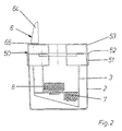
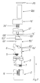
- the first embodiment of the device which serves to fill a printhead 100 is first explained below.
- the print head 100 has a housing 101, on the lower end face of which a nozzle plate 103 is attached. Opposite the housing 101 carries a cover 102 which has a bore 106.
- the bore 106 serves on the one hand as a ventilation bore, on the other hand as a filler bore for the ink supply space located within the housing 101 and not shown here.
- the ink supply space is largely filled with a very strongly liquid-absorbing material. This can be a sponge-like material or a highly absorbent fleece.
- the device has two main assemblies, namely a holder 4 and a cannula holder 18.
- the holder 4 is constructed from a holder insert 3, a housing 2 and a latch 5.
- the holder insert 3 carries a sealing member 7, which is intended to seal the nozzle plate 103.
- an adapter 6 is provided in the present case to adapt to the geometry of the print head 100, which additionally carries a sealing element 8.
- the sealing member 8 has no sealing function because the print head 100 has no ventilation opening on its underside.
- the sealing element 8 follows the contour of the underside of the housing of the printhead 100 and can serve as additional support.
- the cannula holder 18 has latching hooks 14 which are intended to engage on the holder insert 3.
- the ink supply is supplemented by a refill cartridge 200, which is closed by a releasable closure cap 210 at its upper end.
- the initial state is shown schematically in FIG.
- the bracket insert 3 is inserted into the housing 2.
- the holder insert 3 has a cuff-shaped edge profile 50 at the upper end, with an outwardly pointing profile section 51 encompassing the housing 2 in the upper region overlapping and encircling.
- the profile section 51 merges into an edge web 53 in the form of a shoulder.
- the heel 52 formed in this way serves as a support surface for the cannula carrier 18, which has an overlap with the edge web 53.
- the sealing member 7 is attached.
- the adapter 6 is loosely inserted into the holder insert 3. It has an essentially L-shaped cross section. In the upper area of the adapter 6, a stop edge 65 is formed, which comes into contact with the mounting insert 3. Furthermore, a vertically standing rib 64 is present in this area, which serves as a gripping surface for handling the adapter 6.
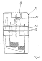
- FIG. 3 the print head 100 is inserted into the holder 4.
- the housing 101 is completely accommodated by the holder 4, the adapter 6 being held inside by the printhead 100 used.
- the cover 102 of the print head 100 protrudes from the holder 4.
- the cannula holder 18 is placed. At its lower end it rests on the shoulder 52 of the edge profile 50 on the mounting insert 3. It also has overlapping contact with the edge web 53 of the edge profile 50. As a result, the cannula carrier 18 is held in place as a result of the friction effect. In addition, locking hooks can be locked on the holder 4, for example in the region of the edge profile 50, in a manner not shown here.
- a cannula 17 is attached to the cannula carrier 18.
- the position of the cannula 17 is selected such that it corresponds to the bore 106 in the lid 102 and penetrates it in the state shown.
- the length of the cannula 17 is dimensioned downwards so that it protrudes at least halfway into the ink supply space. This ensures that even deeper layers of the ink collecting space can be filled with ink sufficiently quickly.
- the cannula 17 penetrates the cannula carrier 18 in the region of a depression 16.
- the tip of the cannula 17 still ends within the depression 16, so that there is no acute risk of injury from the tip of the cannula 17.
- the recess 16 is designed in the shape of a circular cylinder in order to enclose the cylindrical housing 201 of the refill cartridge 200 in the lower region.
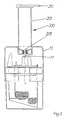
- the refill cartridge 200 is placed on the cannula holder 18.
- the cannula 17 has pierced the plug 205 and there is a connection between the ink reservoir and the inside of the refill cartridge 200.
- the refill cartridge 200 is still closed with the cap 210 in the situation shown.
- the cap 210 is removed, the interior of the refill cartridge 200 is thus ventilated and the filling process can take place automatically.
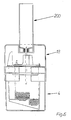
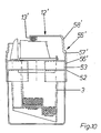
- FIG. 7 shows a device which is used to fill a printhead 100 '.
- This has a housing 101 ', on the underside of which a nozzle plate 103' and a ventilation opening 104 'are attached.
- the housing 101 ' is closed at the top by a cover 102' which has a bore 106 'in addition to a further ventilation opening 105'.
- the bore 106 ' is sealed in the factory with a ball, not shown here.
- the structure of the holder 4 is in accordance with the design of the device of the first embodiment.
- the sealing element 8, which is attached to the adapter 6, has the task of sealingly closing the ventilation opening 104 'on the underside of the housing 101' of the printhead 100 '.
- seal carrier 12 ' This has the function described in more detail below to seal the ventilation opening 105 'located on the cover 102'.
- the seal carrier 12 ' can be placed on the mounting insert 3 and fixed by means of locking hooks 14'.
- Figure 10 shows the configuration with the seal carrier 12 'attached.
- the seal carrier 12 ' has the task of holding a sealing member 13' pressed against the ventilation opening 105 'located in the cover 102' and sealing it.
- the seal carrier 12 ' has at its our end an edge profile 55' with a lower profile section 56 '.
- the edge profile 56' is in contact with the edge web 53 of the mounting insert 3.
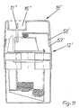
- Figure 11 shows the device with attached cannula carrier 18 ', which rests on the shoulder 57 of the seal carrier 12'.
- the cannula carrier 18 ' is also in contact with the profile section 58' and is held in place due to the friction effect. Further fixing members, not shown here, can additionally secure the cannula carrier 18 '.
- the cannula holder 18 ' has a recess 16' which is matched to the shape of the refill cartridge 200. In the area of the recess 16 'there is the cannula 17' Position is matched to the bore 106 'of the printhead 100.
- the cannula 17 ' only penetrates a short distance into the ink supply space, since it is not, as in the case of the print head 100, filled with a liquid-absorbing material, but is designed as a cavity and is penetrated by the plastic bags described at the beginning.
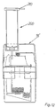
- FIG. 12 finally shows the refill cartridge 200 which is placed on the cannula carrier 18 'and which is still closed with the cap 210.
- a large number of printheads on the market can be filled easily and safely.
- the modular structure of the devices provides the greatest possible flexibility.
- devices or kits can be put together, which are either adapted to a certain type of print heads, or which are universally suitable for the different types of print heads. In the latter case, it is only necessary to provide, for example in addition to the device with the cannula carrier 18, a further cannula carrier 18 'and a seal carrier 12'.
Abstract
Description
Die Erfindung betrifft eine Vorrichtung zum Befüllen eines Druckkopfs eines Tintenstrahldruckers gemäß Anspruch 1, ein Kit zum Befüllen eines Druckkopfs eines Tintenstrahldruckers gemäß Anspruch 13, sowie zwei Verfahren zum Befüllen eines Druckkopfs eines Tintenstrahldruckers gemäß Anspruch 17 und 18.The invention relates to a device for filling a printhead of an inkjet printer according to claim 1, a kit for filling a printhead of an inkjet printer according to
Bislang wurden Druckköpfe für Tintenstrahldrucker in der Regel als Einwegprodukt geliefert. Nach dem Verbrauch des Tintenvorrats wurden die Druckköpfe verworfen und durch neue ersetzt. Dies ist aus ökologischer Sicht unerwünscht, da die verbrauchten Druckkopfe an sich noch vollständig funktionsfähig sind und außerdem eine Reihe wertvoller Bestandteile, wie beispielsweise die Düsenplatte, durch die die Tinte ausgespritzt wird, oder die Kontaktfolie, die die elektrischen Signale zur Steuerung des Ausspritzvorgangs erzeugt, eine Lebensdauer aufweisen, die erheblich über den Zeitraum der einmaligen Benutzung hinausgeht.So far, printheads for inkjet printers have generally been supplied as single-use products. After the ink supply was used up, the printheads were discarded and replaced with new ones. This is undesirable from an ecological point of view, since the used print heads are still fully functional and also contain a number of valuable components, such as the nozzle plate through which the ink is ejected, or the contact foil, which generates the electrical signals for controlling the ejection process. have a lifespan that extends significantly beyond the period of single use.
Auch sind bereits Vorschläge bekannt geworden, derartige Druckköpfe durch geeignete Maßnahmen wiederzubefüllen und damit deren Lebensdauer zu verlängern.Proposals have already become known, such Refill printheads with suitable measures and thus extend their lifespan.
Beispielsweise ist aus der WO 92/20577 ein Nachfüllbehälter bekannt, der mit einer Hohlnadel versehen ist. Die Hohlnadel wird durch eine Öffnung im Gehäuse des Druckkopfs eingeführt und dringt dadurch in einen Tintenvorratsraum ein, welcher beispielsweise aus einem schwammartigen Material besteht. Durch Druck auf den elastisch deformierbar gestalteten Nachfüllbehälter wird die darin befindliche Tinte über die Hohlnadel dem Tintenvorratsraum zugeführt.For example, a refill container is known from WO 92/20577, which is provided with a hollow needle. The hollow needle is inserted through an opening in the housing of the printhead and thereby penetrates into an ink supply space, which consists for example of a sponge-like material. By pressure on the elastically deformable refill container, the ink inside is fed to the ink reservoir via the hollow needle.
Obwohl sich der dort beschriebene Nachfüllbehälter grundsätzlich eignet, einen Druckkopf wiederzubefüllen, treten in der praktischen Handhabung eine Reihe von Problemen auf. Bei denjenigen Druckköpfen, die lediglich eine Öffnung besitzen, durch die der Tintenvorratsraum zugänglich ist, ist in der Regel nicht zu verhindern, daß Tinte während des Nachfüllvorgangs aus der Düsenplatte austritt. Dies ist die Folge des sich kurzzeitig aufbauenden Überdrucks durch das Zuführen von Tinte. Der Druckausgleich mit der Umgebung kann durch die in die Öffnung eingesetzte Hohlnadel nicht ausreichend schnell erfolgen, so daß Tinte durch die Düsenplatte ausgedrückt wird. Es ist deshalb erforderlich, den Druckkopf für die Dauer des Befüllvorgangs auf eine saugfähige Unterlage, wie beispielsweise ein Vlies, zu stellen, damit die austretende Tinte aufgefangen wird. Auch ist es zweckmäßig, den Befüllvorgang langsam und ggf. mit kürzeren Pausen intervallmäßig durchzuführen, um einen ausreichenden Druckausgleich zu ermöglichen und den unvermeidlichen Tintenaustritt so gering wie möglich zu halten.Although the refill container described there is fundamentally suitable for refilling a printhead, a number of problems arise in practical handling. For those printheads that only have an opening through which the ink supply space is accessible, it is generally not possible to prevent ink from escaping from the nozzle plate during the refilling process. This is the result of the temporary build-up of excess pressure due to the supply of ink. The pressure equalization with the environment can not be done quickly enough by the hollow needle inserted into the opening, so that ink is squeezed out through the nozzle plate. It is therefore necessary to place the printhead on an absorbent pad, such as a fleece, for the duration of the filling process, so that the emerging ink is caught. It is also expedient to carry out the filling process slowly and, if necessary, with shorter pauses at intervals, in order to enable adequate pressure compensation and to keep the inevitable ink leakage as low as possible.
Der Nachfüllvorgang gestaltet sich demnach nicht unproblematisch, da die austretende Tinte die Gefahr von Verschmutzungen mit sich bringt. Es ist sorgfältig darauf zu achten, daß sich der erforderliche Druckausgleich vollziehen kann. Das Wiederbefüllen erfordert deshalb die sorgfältige Beachtung der angesprochenen Randbedingungen, die in der zuweilen zu beobachtenden Hektik des Büroalltags nicht immer eingehalten werden.The refilling process is therefore not unproblematic, since the emerging ink creates the risk of contamination brings with it. Care must be taken to ensure that the necessary pressure equalization can take place. Refilling therefore requires careful consideration of the marginal conditions mentioned, which are not always adhered to in the hectic pace of everyday office life that can sometimes be observed.
Die Bedienung verkompliziert sich erheblich, sofern Druckköpfe neuerer Konzeption mit einem aufwendigen Be- und Entlüftungssystem auf diese Art wiederbefüllt werden sollen. Diese Art von Druckköpfen besitzen in ihrem Inneren flexible Kunststoffsäcke, die während des Druckvorgangs über eine Belüftungsöffnung mit Luft beaufschlagt werden. Für eine einwandfreie Funktion des Druckkopfs ist eine weitere Belüftungsöffnung erforderlich. Derartige Druckköpfe besitzen deshalb eine erste Belüftungsöffnung im Bereich des Deckels und eine zweite Belüftungsöffnung in der Nähe der gegenüberliegend angeordneten Düsenplatte. Weiterhin ist eine im Gehäusedeckel angebrachte Einfüllöffnung vorhanden, die den Zugang zum Tintenvorratsraum ermöglicht. Die Einfüllöffnung ist werksseitig mit einer Kugel dicht verschlossen.Operation is considerably complicated if printheads of a more recent design are to be refilled in this way with an elaborate ventilation system. This type of print head has flexible plastic sacks inside, which are pressurized with air during the printing process via a ventilation opening. A further ventilation opening is required for the printhead to function properly. Such print heads therefore have a first ventilation opening in the area of the cover and a second ventilation opening in the vicinity of the nozzle plate arranged opposite. There is also a filler opening in the housing cover, which enables access to the ink supply room. The filling opening is sealed with a ball at the factory.
Das Wiederbefüllen eines derartigen Druckkopfes ist aufgrund des ausgeklügelten Be- und Entlüftungssystems weitaus komplizierter und erfordert die strikte Einhaltung einer bestimmten Reihenfolge von Arbeitsschritten. So muß zunächst die im Bereich der Düsenplatte befindliche Belüftungsöffnung abgedichtet werden. Dies geschieht beispielsweise durch Abkleben der Öffnung mit einer Abdichtfolie. Danach muß die gegenüberliegend am Gehäusedeckel angebrachte Belüftungsöffnung, beispielsweise mit einem Verschlußstopfen, dicht verschlossen werden. Auch müssen die Düsen verschlossen werden, damit beim Befüllvorgang keine Tinte austreten kann. Im Anschluß daran ist die Kugel aus der Einfüllöffnung durch Eindrücken zu entfernen. Nunmehr kann z. B. mit dem oben beschriebenen Nachfüllbehälter der Tintenvorrat ergänzt werden. Auch hier ist darauf zu achten, daß der Nachfüllvorgang ausreichend langsam erfolgt, um den Druckausgleich zu ermöglichen.Refilling such a printhead is much more complicated due to the sophisticated ventilation system and requires strict adherence to a specific sequence of work steps. The ventilation opening in the area of the nozzle plate must first be sealed. This is done, for example, by masking the opening with a sealing film. Then the ventilation opening on the opposite side of the housing cover must be sealed, for example with a sealing plug. The nozzles must also be closed so that no ink can escape during the filling process. The ball is then out of the filler opening Remove indentation. Now z. B. with the refill container described above, the ink supply. It is also important to ensure that the refilling process is slow enough to allow pressure equalization.
Nach Beendigung des Befüllvorgangs muß zunächst die Einfüllöffnung mit einem Verschließstopfen dicht verschlossen werden. Danach wird zunächst die am Gehäusedeckel befindliche Belüftungsöffnung freigegeben und schließlich die Abdichtfolie von der gegenüberliegenden, in der Nähe der Düsenplatte befindlichen Belüftungsöffnung abgezogen.After the filling process has been completed, the filling opening must first be sealed with a sealing plug. Thereafter, the ventilation opening on the housing cover is first released and finally the sealing film is pulled off from the opposite ventilation opening located near the nozzle plate.
Bei derartigen Druckköpfen ist die Abdichtung der beiden Belüftungsöffnungen von immenser Bedeutung. Wird dies versäumt und lediglich zum Befüllen die Einfüllöffnung freigegeben, so fließt die Tinte innerhalb kurzer Zeit aus den Düsen und der benachbart angeordneten Belüftungsöffnung.With such printheads, the sealing of the two ventilation openings is of immense importance. If this is neglected and the filler opening is only opened for filling, the ink will flow out of the nozzles and the adjacent ventilation opening within a short time.
Der vorliegenden Erfindung lag deshalb das Problem zugrunde, das Befüllen, insbesondere das Wiederbefüllen, eines Druckkopfs eines Tintenstrahldruckers zu verbessern und sicherer zu gestalten, so daß Fehlbedienungen weitgehend ausgeschlossen sind und Verschmutzungen sicher vermieden werden.The present invention was therefore based on the problem of improving the filling, in particular the refilling, of a printhead of an inkjet printer and making it safer, so that incorrect operation is largely excluded and contamination is reliably avoided.
Gelöst wird dieses Problem durch eine Vorrichtung, wie sie durch die Merkmale des Anspruchs 1 beschrieben ist. Vorteilhafte Ausgestaltungen der Vorrichtung sind durch die sich hieran anschließenden Unteransprüche wiedergegeben.This problem is solved by a device as described by the features of claim 1. Advantageous embodiments of the device are given by the subclaims that follow.
Das Problem wird ferner durch ein Kit gelöst, welches durch die Merkmale des Anspruchs 13 definiert ist. Vorteilhafte Weiterbildungen des Kits sind durch die nachgeschalteten Unteransprüche angegeben.The problem is further solved by a kit, which is defined by the features of
Das Problem wird schließlich durch die in den Ansprüchen 17 und 18 wiedergegebenen verfahren gelöst.The problem is finally solved by the method set out in
Der Erfindung liegt die Idee zugrunde, eine Vorrichtung zur Verfügung zu stellen, in die der zu befüllende Druckkopf eingesetzt werden kann. Durch spezielle, auf den jeweiligen Druckkopf abgestimmte Zusatzelemente, die auf den Druckkopf bzw. auf die Halterung aufgesetzt werden, werden die Belüftungsöffnungen und die Düsenplatte dicht verschlossen, sowie der Zugang zum Tintenvorratsraum hergestellt. Hierzu ist eine Halterung mit Dichtungsorganen vorgesehen, in welche der Druckkopf mit geringem seitlichem Spiel und mit nach unten weisender Düsenplatte einsetzbar ist. Die Düsenplatte ist gegen das Dichtungsorgan gerichtet und wird daran zur dichtenden Anlage mittels eines Arretierorgans gebracht. Auf den derart eingesetzten Druckkopf ist ein Kanülenträger aufsetzbar. Der Kanülenträger besitzt eine Kanüle, welche in die im Deckelbereich des Druckkopfs befindliche Bohrung in das Innere des Druckkopfs und damit in den Tintenvorratsraum eindringt. Sie stellt die kommunizierende Verbindung zu einer Nachfüllpatrone her, die von oben auf die Kanüle aufsteckbar ist.The invention is based on the idea of providing a device in which the printhead to be filled can be inserted. The ventilation openings and the nozzle plate are sealed and special access to the ink supply space is established by means of special additional elements that are matched to the respective print head and which are placed on the print head or on the holder. For this purpose, a holder with sealing elements is provided, in which the print head can be inserted with little lateral play and with the nozzle plate pointing downwards. The nozzle plate is directed against the sealing member and is brought to the sealing system by means of a locking member. A cannula holder can be placed on the printhead used in this way. The cannula holder has a cannula which penetrates into the bore in the lid area of the printhead into the interior of the printhead and thus into the ink supply space. It establishes the communicating connection to a refill cartridge that can be attached to the cannula from above.
Diese Grundversion einer Vorrichtung ist für solche Druckköpfe konzipiert, die lediglich eine einzige Belüftungsöffnung, beispielsweise im Deckelbereich, aufweisen. Durch die Abdichtung der Düsenplatte kann dort keine Tinte mehr austreten, Verschmutzungen des Untergrunds treten nicht mehr auf. Auch gestaltet sich die Zufuhr von Tinte besonders einfach, da nach dem Einstechen der Kanüle in die Nachfüllpatrone der Tintenvorrat selbsttätig durch atmosphärischen Druck und Kapillarwirkung in den Tintenvorratsraum fließt. Eine zusätzliche Betätigung ist nicht erforderlich.This basic version of a device is designed for print heads that only have a single ventilation opening, for example in the lid area. Due to the sealing of the nozzle plate, ink can no longer escape there, soiling of the surface no longer occurs. The supply of ink is also particularly simple since, after the needle has been inserted into the refill cartridge, the ink supply flows automatically into the ink supply space due to atmospheric pressure and capillary action. Additional actuation is not necessary.
Nach dem Leerlaufen der Nachfüllpatrone braucht diese lediglich von der Kanüle abgezogen und der Kanülenträger vom Druckkopf abgenommen zu werden. Der Druckkopf steht damit sofort einsatzbereit zur Verfügung.After the refill cartridge has run dry, it only needs to be removed from the cannula and the cannula holder removed from the print head. The printhead is thus immediately ready for use.
Für Druckköpfe, die weitere Belüftungsöffnungen, beispielsweise in der Nähe der Düsenplatte besitzen, sind gem. einer Ausführungsvariante zusätzliche Dichtorgane vorgesehen. Da diese Druckköpfe darüber hinaus häufig eine abweichende Geometrie aufweisen, ist vorteilhafterweise in die Halterung ein Adapter einsetzbar, so daß die Vorrichtung für eine Vielzahl unterschiedlicher Druckköpfe verwendet werden kann. In diesem Falle können die zusätzlichen Dichtungsorgane am Adapter angebracht sein, so daß zwangsweise die korrekte Zuordnung von Dichtungselement und Belüftungsöffnung erreicht wird.For printheads that have further ventilation openings, for example in the vicinity of the nozzle plate, according to. In one embodiment, additional sealing elements are provided. Since these printheads also often have a different geometry, an adapter can advantageously be inserted into the holder, so that the device can be used for a large number of different printheads. In this case, the additional sealing members can be attached to the adapter, so that the correct assignment of sealing element and ventilation opening is necessarily achieved.
Die erforderliche Anpreßkraft zwischen Dichtungselement und Druckkopf läßt sich auf einfache Art und Weise durch eine Rastklinke erreichen, die an einer der Gehäusekanten des Druckkopfs angreift.The required contact pressure between the sealing element and the printhead can be achieved in a simple manner by means of a latch which engages one of the housing edges of the printhead.
Für diejenigen Druckköpfe, die im Bereich des Gehäusedeckels eine Belüftungsöffnung aufweisen, ist ein Dichtungsträger vorgesehen, der ein Dichtungsorgan aufweist und auf den Druckkopf aufsetzbar ist. Zur Erzielung des erforderlichen Anpreßdrucks kann der Dichtungsträger Rasthaken besitzen, die bevorzugtin die Halterung einrasten. Der Dichtungsträger und der Kanülenträger sind gem. einer bevorzugten Ausführungsform hinsichtlich ihrer geometrischen Gestaltung derart aufeinander abgestimmt, daß sie lediglich in der vorgesehenen Reihenfolge aufeinander aufgesetzt und nach dem Befüllen wieder voneinander gelöst werden können. So ist es, wie eingangs detailliert beschrieben, erforderlich, zunächst sämtliche Belüftungsöffnungen zu verschließen, bevor die Kanüle in den Tintenvorratsraum eingebracht werden kann. Ebenso muß nach erfolgtem Befüllen die Einhaltung einer bestimmen Abfolge von Schritten eingehalten werden. Aus diesem Grund ist der Kanülenträger so gestaltet, daß er erst dann auf den Druckkopf aufgesetzt werden kann, wenn zuvor der Dichtungsträger angebracht wurde. Umgekehrt läßt sich der Dichtungsträger erst dann entfernen, wenn zuvor der Kanülenträger abgehoben wurde.For those printheads that have a ventilation opening in the area of the housing cover, a seal carrier is provided, which has a sealing member and can be placed on the printhead. To achieve the required contact pressure, the seal carrier can have latching hooks, which preferably snap into the holder. The seal carrier and the cannula carrier are gem. a preferred embodiment in terms of their geometric design so coordinated that they can only be placed on each other in the intended order and detached from each other after filling. That's the way it is, As described in detail at the beginning, it is necessary to first close all ventilation openings before the cannula can be introduced into the ink supply space. Likewise, after completing the filling, a certain sequence of steps must be observed. For this reason, the cannula carrier is designed so that it can only be placed on the print head when the seal carrier has been attached beforehand. Conversely, the seal carrier can only be removed if the cannula carrier has been lifted off beforehand.
Im konkreten Fall wird dies einfach dadurch gelöst, daß sowohl der Dichtungsträger als auch die Halterung mit einem speziellen umlaufenden Randprofil versehen sind, die als gegenseitige Anlageflächen bzw. als Anlagefläche für den Kanülenträger dienen. Jeweils abgestufte Absätze erlauben die Anordnung nur in der vorgegebenen Reihenfolge.In the specific case, this is simply achieved in that both the seal carrier and the holder are provided with a special circumferential edge profile, which serve as mutual contact surfaces or as a contact surface for the cannula carrier. Graded paragraphs only allow the arrangement in the specified order.
Der Kanülenträger weist bevorzugt eine Vertiefung im Bereich der Kanüle auf, die auf die aufzusetzende Nachfüllpatrone abgestimmt ist und diese in ihrem unteren Bereich führend umfaßt. Dies erlaubt ein sicheres Aufsetzen der Nachfüllpatrone auf den Kanülenträger.The cannula holder preferably has a recess in the area of the cannula, which is matched to the refill cartridge to be fitted and which has a leading area in its lower area. This allows the refill cartridge to be placed securely on the cannula holder.
Weitere Vorteile lassen sich erzielen, wenn der Kanülenträger und der ggf. vorhandene Dichtungsträger aus transparentem Material gefertigt sind. So kann der Befüllvorgang daraufhin überwacht werden, ob Tinte aus der Einfüllöffnung austritt und deshalb der Befüllvorgang durch Abziehen der Nachfüllpatrone beendet werden muß. Obwohl das Volumen der Nachfüllpatrone auf das Aufnahmevermögen des Tintenvorratsraums abgestimmt und deshalb ein Überfüllen kaum möglich ist, kann es dennoch zu einem unbeabsichtigten Austreten von Tinte dann kommen, wenn der Druckkopf wiederbefüllt wird, bevor der ursprüngliche Tintenvorrat aufgebraucht ist.Further advantages can be achieved if the cannula carrier and the seal carrier, if any, are made of transparent material. The filling process can thus be monitored to determine whether ink is escaping from the filling opening and therefore the filling process must be ended by pulling off the refill cartridge. Although the volume of the refill cartridge is matched to the capacity of the ink reservoir and therefore overfilling is hardly possible, there can still be an unintentional leakage of ink when the printhead is refilled. before the original ink supply runs out.
Das Befüllen eines Druckkopfs läßt sich weiterhin optimieren, wenn die Vorrichtung und die Nachfüllpatronen aufeinander abgestimmt, d. h. nach Art eines Kits, hergerichtet sind. Bevorzugt besteht die Nachfüllpatrone aus einem zylindrischen Gehäuse, das einenends mit einem Stopfen verschlossen ist, der von der Kanüle leicht durchstoßen werden kann, um die Flüssigkeitsverbindung zwischen der Patrone und dem Tintenvorratsraum des Druckkopfs herzustellen. Für das selbsttätige Leerlaufen der Patrone ist es erforderlich, eine Belüftungsmöglichkeit vorzusehen. Dies kann durch ein anderenends angebrachtes, lösbares Verschlußorgan, beispielsweise in Form eines Korkens, eines Stopfens, einer Kappe, eines Schraubdeckels, einer aufgeklebten Folie oder einer aufgeschweißten Folie realisiert sein.The filling of a printhead can be further optimized if the device and the refill cartridges are matched to one another, i. H. are prepared in the manner of a kit. The refill cartridge preferably consists of a cylindrical housing which is closed at one end with a stopper which can be easily pierced by the cannula in order to establish the fluid connection between the cartridge and the ink reservoir of the printhead. To automatically empty the cartridge, it is necessary to provide ventilation. This can be achieved by a detachable closure member attached at the other end, for example in the form of a cork, a stopper, a cap, a screw cap, a glued-on film or a welded-on film.
Besonders vorteilhaft ist es, den von der Kanüle durchstoßbaren Stopfen aus selbstverschließendem Material zu fertigen. Dadurch kann der Befüllvorgang durch Abziehen der Nachfüllpatrone von der Kanüle jederzeit unterbrochen und zu einem späteren Zeitpunkt oder bei einem weiteren Druckkopf fortgesetzt werden. Beim Abziehen der Nachfüllpatrone verschließt sich der Stopfen selbsttätig und verhindert ein unbeabsichtigtes Austreten von Tinte.It is particularly advantageous to manufacture the plug that can be penetrated by the cannula from self-closing material. As a result, the filling process can be interrupted at any time by pulling the refill cartridge off the cannula and continued at a later point in time or with another print head. When the refill cartridge is removed, the stopper closes automatically and prevents ink from escaping unintentionally.
Mit Hilfe der erfindungsgemäßen Vorrichtungen einschließlich der dazugehörigen Nachfüllpatronen können die meisten der im Handel erhältlichen Druckköpfe auf einfache Art und Weise wiederbefüllt werden.With the help of the devices according to the invention, including the associated refill cartridges, most of the commercially available print heads can be refilled in a simple manner.
Mit Hilfe eines ersten Verfahrens gelingt das Befüllen von Druckköpfen, deren Tintenvorratsraum von oben durch eine Belüftungsbohrung im Deckel zugänglich ist. Hierzu wird eine Vorrichtung verwendet, die im wesentlichen aus den Hauptbaugruppen Halterung und Kanülenträger besteht. Zunächst wird in die Halterung der Druckkopf eingesetzt und die Düsenplatte durch Verrasten des Gehäuses mit dem Arretierorgan abgedichtet. Danach wird die Kanüle in den Tintenvorratsraum durch Aufsetzen des Kanülenträgers auf den Druckkopf eingebracht. Damit ist der Druckkopf für den eigentlichen Befüllvorgang vorbereitet. Die Nachfüllpatrone wird auf den Kanülenträger aufgesetzt, wobei während des Aufsetzvorgangs die Kanüle den Stopfen der Nachfüllpatrone durchstößt. Durch Lösen oder Entfernen des Verschlußorgans wird die Nachfüllpatrone belüftet und die Tinte fließt selbsttätig in den Tintenvorratsraum. Nach dem Leerlaufen der Nachfüllpatrone bzw. bei Erreichen des gewünschten Befüllzustandes wird die Nachfüllpatrone von der Kanüle abgezogen, so daß nach dem Abnehmen des Kanülenträgers der befüllte Druckkopf unmittelbar entnommen werden kann.With the aid of a first method, it is possible to fill printheads whose ink supply space is accessible from above through a ventilation hole in the lid. For this, a Device used, which consists essentially of the main assemblies bracket and cannula holder. First, the print head is inserted into the holder and the nozzle plate is sealed by locking the housing with the locking element. The cannula is then introduced into the ink supply space by placing the cannula holder on the printhead. The print head is now ready for the actual filling process. The refill cartridge is placed on the cannula holder, the cannula piercing the stopper of the refill cartridge during the fitting process. By loosening or removing the closure member, the refill cartridge is ventilated and the ink automatically flows into the ink reservoir. After the refill cartridge has run dry or when the desired filling state has been reached, the refill cartridge is withdrawn from the cannula so that the filled print head can be removed immediately after the cannula holder has been removed.
Mit einem zweiten Verfahren können diejenigen Druckköpfe befüllt werden, die das eingangs beschriebene aufwendige Be- und Entlüftungssystem aufweisen. Hierzu wird eine Vorrichtung verwendet, die neben den Hauptbaugruppen Halterung und Kanülenträger zusätzlich den Dichtungsträger umfaßt.A second method can be used to fill those printheads which have the complex ventilation system described above. For this purpose, a device is used which, in addition to the main assemblies of holder and cannula holder, also includes the seal holder.
Zunächst wird wiederum der Druckkopf in die Halterung eingesetzt und das Arretierorgan verrastet. Hierdurch wird nicht nur die Düsenplatte, sondern auch die benachbart zur Düsenplatte angeordnete Belüftungsöffnung abgedichtet. Anschließend wird die oben im Gehäusedeckel befindliche Belüftungsöffnung durch Aufsetzen des Dichtungsträgers auf den Druckkopf verschlossen. Zusätzlich wird durch das Einrasten der Rastklinken der Druckkopf mit erhöhter Anpreßkraft auf die der Düsenplatte und der benachbarten Belüftungsöffnung zugeordneten Dichtungselemente gedrückt. Schließlich wird der Kanülenträger auf den Dichtungsträger aufgesetzt, wodurch die Kanüle in den Tintenvorratsraum eindringt. Nunmehr ist der Druckkopf für den Befüllvorgang vorbereitet.First the print head is inserted into the holder and the locking element is locked. This seals not only the nozzle plate, but also the ventilation opening arranged adjacent to the nozzle plate. Then the ventilation opening at the top of the housing cover is closed by placing the seal carrier on the print head. In addition, by engaging the latches, the print head is pressed with increased contact pressure onto the sealing elements assigned to the nozzle plate and the adjacent ventilation opening. Eventually the cannula carrier is placed on the seal carrier, whereby the cannula penetrates into the ink reservoir. The print head is now ready for the filling process.
Die Nachfüllpatrone wird auf den Kanülenträger aufgesetzt, wobei die Kanüle den Stopfen durchstößt. Danach wird das Verschlußorgan gelöst oder entfernt, so daß die Tinte selbsttätig in den Tintenvorratsraum abfließen kann. Nach Beendigung des Befüllvorgangs wird die Nachfüllpatrone von der Kanüle abgezogen und der Kanülenträger abgehoben. Nunmehr ist die Einfüllbohrung mit einem Verschließstopfen dicht zu verschließen. Erst danach kann der Dichtungsträger abgehoben und der befüllte Druckkopf entnommen werden.The refill cartridge is placed on the cannula holder, the cannula piercing the stopper. The closure member is then loosened or removed so that the ink can flow off into the ink supply space automatically. After the filling process has been completed, the refill cartridge is removed from the cannula and the cannula holder is lifted off. Now the filler hole must be sealed with a sealing plug. Only then can the seal carrier be lifted off and the filled printhead removed.
Die Erfindung wird nachstehend anhand zweier Ausführungsbeispiele näher erläutert. Es zeigen in schematischer Darstellung:
- Figur 1
- Explosionszeichnung der Vorrichtung in einer ersten Ausführungsform einschließlich Nachfüllpatrone,
- Figur 2 - 6
- verschiedene Verfahrensstadien zur Vorbereitung des Befüllvorgangs unter Verwendung einer Vorrichtung gem. Figur 1,
Figur 7- Explosionszeichnung der Vorrichtung in einer zweiten Ausführungsform einschließlich Nachfüllpatrone,
- Figur 8 - 13
- verschiedene Verfahrensschritte zur Vorbereitung des Befüllvorgangs unter Verwendung einer Vorrichtung gem.
Figur 7.
- Figure 1
- Exploded view of the device in a first embodiment including refill cartridge,
- Figure 2-6
- Different stages of the process for preparing the filling process using a device acc. Figure 1,
- Figure 7
- Exploded view of the device in a second embodiment including refill cartridge,
- Figure 8-13
- different process steps for preparing the filling process using a device acc. Figure 7.
Nachfolgend wird zunächst die erste Ausführungsform der Vorrichtung erläutert, die zum Befüllen eines Druckkopfs 100 dient.The first embodiment of the device which serves to fill a
Gern. Figur 1 besitzt der Druckkopf 100 ein Gehäuse 101, an dessen unterer Stirnfläche eine Düsenplatte 103 angebracht ist. Gegenüberliegend trägt das Gehäuse 101 einen Deckel 102, welcher eine Bohrung 106 aufweist. Die Bohrung 106 dient einerseits als Belüftungsbohrung, andererseits als Einfüllbohrung für den innerhalb des Gehäuses 101 befindlichen, hier nicht näher dargestellten Tintenvorratsraum. Der Tintenvorratsraum ist weitgehend von einem sehr stark flüssigkeitsaufnehmenden Material ausgefüllt. Hierbei kann es sich um ein Material nach Art eines Schwamms oder um ein hochsaugfähiges Vlies handeln.Gladly. 1, the
Die Vorrichtung weist zwei Hauptbaugruppen auf, nämlich eine Halterung 4 und einen Kanülenträger 18. Die Halterung 4 ist aus einem Halterungseinsatz 3, einem Gehäuse 2 sowie einer Rastklinke 5 aufgebaut. Der Halterungseinsatz 3 trägt ein Dichtungsorgan 7, welches die Düsenplatte 103 abdichten soll.The device has two main assemblies, namely a
Weiterhin ist im vorliegenden Fall zur Anpassung an die Geometrie des Druckkopfs 100 ein Adapter 6 vorgesehen, der zusätzlich ein Dichtunsorgan 8 trägt. Im vorliegenden Fall ist das Dichtungsorgan 8 ohne Dichtungsfunktion, da der Druckkopf 100 keine Belüftungsöffnung an seiner Unterseite trägt. Das Dichtungselement 8 folgt jedoch dem Konturverlauf der Gehäuseunterseite des Druckkopfs 100 und kann als zusätzliche Abstützung dienen.Furthermore, an
Der Kanülenträger 18 weist Rasthaken 14 auf, die dazu bestimmt sind, am Halterungseinsatz 3 einzugreifen.The
Der Tintenvorrat wird durch eine Nachfüllpatrone 200 ergänzt, die durch eine lösbare Verschlußkappe 210 an ihrem oberen Ende verschlossen ist.The ink supply is supplemented by a
In Figur 2 ist schematisch der Ausgangszustand dargestellt. Der Halterungseinsatz 3 ist in das Gehäuse 2 eingesetzt. Hierzu weist der Halterungseinsatz 3 am oberen Ende ein stulpenförmiges Randprofil 50 auf, wobei ein nach außen weisender Profilabschnitt 51 das Gehäuse 2 im oberen Bereich überlappend und umlaufend umfaßt. Der Profilabschnitt 51 geht absatzförmig nach oben hin in einen Randsteg 53 über. Der hierdurch gebildete Absatz 52 dient als Auflagefläche für den Kanülenträger 18, der überlappend mit dem Randsteg 53 Kontakt hat.The initial state is shown schematically in FIG. The
Im Halterungseinsatz 3 ist das Dichtungsorgan 7 angebracht.In the
In den Halterungseinsatz 3 ist der Adapter 6 lose eingelegt. Er besitzt im wesentlichen einen L-förmigen Querschnitt. Im oberen Bereich des Adapters 6 ist eine Anschlagkante 65 angeformt, die an dem Halterungseinsatz 3 zur Anlage kommt. Weiterhin ist in diesem Bereich eine senkrecht stehende Rippe 64 vorhanden, die als Grifffläche zur Handhabung des Adapters 6 dient.The
In der Darstellung gern. Figur 3 ist der Druckkopf 100 in die Halterung 4 eingesetzt. Das Gehäuse 101 wird dabei vollständig von der Halterung 4 aufgenommen, wobei der Adapter 6 durch den eingesetzten Druckkopf 100 im Inneren gehalten ist. Der Deckel 102 des Druckkopfs 100 ragt aus der Halterung 4 heraus.Gladly in the representation. FIG. 3, the
Hier nicht dargestellt ist die Rastklinke 5, die am Rand des Gehäuses 101 unter Vorspannung zur Anlage gebracht ist und dadurch sicherstellt, daß die Düsenplatte 103 gegen das Dichtungsorgan 7 gedrückt gehalten ist.Not shown here is the
In Figur 4 ist der Kanülenträger 18 aufgesetzt. An seinem unteren Ende ruht er auf dem Absatz 52 des Randprofils 50 am Halterungseinsatz 3. Auch hat er überlappend Kontakt mit dem Randsteg 53 des Randprofils 50. Hierdurch wird der Kanülenträger 18 infolge Reibungswirkung festgehalten. Zusätzlich können in hier nicht dargestellter Art und Weise Rasthaken an der Halterung 4, beispielsweise im Bereich des Randprofils 50, rastend fixiert werden.In Figure 4, the
Am Kanülenträger 18 ist eine Kanüle 17 befestigt. Die Position der Kanüle 17 ist derart gewählt, daß sie mit der Bohrung 106 im Deckel 102 korrespondiert und diese im dargestellten Zustand durchdringt. Die Länge der Kanüle 17 ist nach unten hin so bemessen, daß sie bis mindestens zur Hälfte in den Tintenvorratsraum hineinragt. Dadurch ist sichergestellt, daß auch tieferliegende schichten des Tintenauffangraums ausreichens schnell mit Tinte aufgefüllt werden können.A
Nach oben hin durchdringt die Kanüle 17 den Kanülenträger 18 im Bereich einer Vertiefung 16. Die Spitze der Kanüle 17 endet jedoch noch innerhalb der Vertiefung 16, so daß keine akute Verletzungsgefahr durch die Spitze der Kanüle 17 gegeben ist. Im übrigen ist die Vertiefung 16 kreiszylinderförmig ausgeführt, um das zylinderförmige Gehäuse 201 der Nachfüllpatrone 200 im unteren Bereich zu umfassen.At the top, the
In Figur 5 ist die Nachfüllpatrone 200 auf den Kanülenträger 18 aufgesetzt. Die Kanüle 17 hat den Stopfen 205 durchstoßen, und es besteht eine Verbindung zwischen dem Tintenvorratsraum und dem Inneren der Nachfüllpatrone 200. Die Nachfüllpatrone 200 ist in der dargestellten Situation noch mit der Kappe 210 verschlossen.In Figure 5, the
In der Darstellung gem. Figur 6 ist die Kappe 210 entfernt, das Innere der Nachfüllpatrone 200 ist damit belüftet und der Befüllvorgang kann selbsttätig ablaufen.In the representation acc. 6, the
in Figur 7 ist eine Vorrichtung dargestellt, die zum Befüllen eines Druckkopfs 100' dient. Dieser weist ein Gehäuse 101' auf, an dessen Unterseite eine Düsenplatte 103' sowie eine Belüftungsöffnung 104' angebracht sind. Das Gehäuse 101' wird nach oben hin von einem Deckel 102' verschlossen, der neben einer weiteren Belüftungsöffnung 105' eine Bohrung 106' aufweist. Die Bohrung 106' ist werksseitig mit einer hier nicht dargestellten Kugel dicht verschlossen.FIG. 7 shows a device which is used to fill a printhead 100 '. This has a housing 101 ', on the underside of which a nozzle plate 103' and a ventilation opening 104 'are attached. The housing 101 'is closed at the top by a cover 102' which has a bore 106 'in addition to a further ventilation opening 105'. The bore 106 'is sealed in the factory with a ball, not shown here.
Der Aufbau der Halterung 4 ist in Übereinstimmung mit der Konzeption der Vorrichtung des ersten Ausführungsbeispiels. Im Unterschied hierzu hat jedoch das Dichtungsorgan 8, das am Adapter 6 angebracht ist, die Aufgabe, die Belüftungsöffnung 104' an der Unterseite des Gehäuses 101' des Druckkopfs 100' dicht zu verschließen.The structure of the
Der wesentliche Unterschied zur Vorrichtung der ersten Ausführungsform besteht jedoch darin, daß zusätzlich ein weiteres Hauptbauteil, nämlich ein Dichtungsträger 12' vorhanden ist. Dieser hat die nachfolgend detaillierter beschriebene Funktion, die am Deckel 102' befindliche Belüftungsöffnung 105' dicht zu verschließen. Der Dichtungsträger 12' ist auf den Halterungseinsatz 3 aufsetzbar und mittels Rasthaken 14' fixierbar. Ein Kanülenträger 18' ist auf dem Dichtungsträger 12' aufsetzbar.The essential difference to the device of the first embodiment, however, is that there is an additional main component, namely a seal carrier 12 '. This has the function described in more detail below to seal the ventilation opening 105 'located on the cover 102'. The seal carrier 12 'can be placed on the mounting
Die in Figur 8 dargestellte Ausgangssituation ist in Übereinstimmung mit derjenigen aus Figur 2.The initial situation shown in FIG. 8 is in agreement with that from FIG. 2.
Dies gilt auch für die Postion gem. Figur 9, die in Übereinstimmung mit der Position gem. Figur 3 ist. Funktionell besteht jedoch der Unterschied darin, daß das Dichtungsorgan 8 gegen die Unterseite des Gehäuses 101' gedrückt behalten ist, um die dort befindliche Belüftungsöffnung 104' abzudichten.This also applies to the position according to Figure 9, which in accordance with the position acc. Figure 3 is. Functionally, however, the difference is that the sealing
Figur 10 zeigt die Konfiguration mit dem aufgesetzten Dichtungsträger 12'. Der Dichtungsträger 12' hat die Aufgabe, ein Dichtungsorgan 13' gegen die im Deckel 102' befindliche Belüftungsöffnung 105' gedrückt zu halten und diese abzudichten.Figure 10 shows the configuration with the seal carrier 12 'attached. The seal carrier 12 'has the task of holding a sealing member 13' pressed against the ventilation opening 105 'located in the cover 102' and sealing it.
Der Dichtungsträger 12' besitzt an seinem unseren Ende ein Randprofil 55' mit einem unteren Profilabschnitt 56'. Der Profilabschnitt 56' ruht auf dem Randsteg 52 des Halterungseinsatzes 3. An seiner Innenseite hat das Randprofil 56' Kontakt mit dem Randsteg 53 des Halterungseinsatzes 3. Der Profilabschnitt 56' geht in Form eines Absatzes 57' in einen weiteren Profilabschnitt 58' über.The seal carrier 12 'has at its our end an edge profile 55' with a lower profile section 56 '. The profile section 56 'rests on the
Figur 11 zeigt die Vorrichtung mit aufgesetztem Kanülenträger 18', der auf dem Absatz 57 des Dichtungsträgers 12' ruht. Der Kanülenträger 18' hat außerdem Kontakt mit dem Profilabschnitt 58' und wird infolge Reibungswirkung festgehalten. Weitere, hier nicht näher dargestellte Fixierorgane können den Kanülenträger 18' zusätzlich sichern.Figure 11 shows the device with attached cannula carrier 18 ', which rests on the
Der Kanülenträger 18' besitzt eine Vertiefung 16', die auf die Form der Nachfüllpatrone 200 abgestimmt ist. Im Bereich der Vertiefung 16' befindet sich die Kanüle 17', deren Position auf die Bohrung 106' des Druckkopfs 100 abgestimmt ist. Die Kanüle 17' dringt lediglich ein kurzes Stück in den Tintenvorratsraum ein, da dieser nicht, wie im Falle des Druckkopfs 100 mit einem flüssigkeitsaufnehmenden Material gefüllt, sondern als Hohlraum ausgebildet ist und von den eingangs beschriebenen Kunststoffsäcken durchsetzt ist.The cannula holder 18 'has a recess 16' which is matched to the shape of the
Figur 12 zeigt schließlich die auf den Kanülenträger 18' aufgesetzte Nachfüllpatrone 200, die noch mit der Kappe 210 verschlossen ist.FIG. 12 finally shows the
In Figur 13 ist die Kappe 210 entfernt, der Befüllvorgang kann nunmehr selbsttätig ablaufen.In Figure 13, the
Nach dem beschriebenen Prinzip lassen sich eine Vielzahl, im Handel befindlicher Druckköpfe einfach und sicher befüllen. Durch den modularen Aufbau der Vorrichtungen ist eine größtmögliche Flexibilität gegeben. Je nach Zusammenstellung der Hauptbaugruppen lassen sich Vorrichtungen bzw. Kits zusammenstellen, die entweder auf eine bestimmte Art von Druckköpfen abgestimmt sind, oder aber universell für die verschiedenen Druckkopftypen geeignet sind. Im letzteren Fall ist es lediglich erforderlich, beispielsweise zusätzlich zur Vorrichtung mit dem Kanülenträger 18 einen weiteren Kanülenträger 18' und einen Dichtungsträger 12' vorzusehen.According to the principle described, a large number of printheads on the market can be filled easily and safely. The modular structure of the devices provides the greatest possible flexibility. Depending on the composition of the main assemblies, devices or kits can be put together, which are either adapted to a certain type of print heads, or which are universally suitable for the different types of print heads. In the latter case, it is only necessary to provide, for example in addition to the device with the
- 22nd
- Gehäusecasing
- 33rd
- HalterungseinsatzBracket insert
- 44th
- Halterungbracket
- 55
- Arretierorgan, RastklinkeLocking device, latch
- 66
- Adapteradapter
- 77
- DichtungsorganSealing member
- 88th
- DichtungsorganSealing member
- 12'12 '
- DichtungsträgerSeal carrier
- 13'13 '
- DichtungsorganSealing member
- 14, 14'14, 14 '
- Fixierorgane, RasthakenFixing elements, locking hooks
- 16, 16'16, 16 '
- Vertiefungdeepening
- 17, 17'17, 17 '
- KanüleCannula
- 18, 18'18, 18 '
- KanülenträgerCannula holder
- 1919th
- GriffbereichGrip area
- 29, 29'29, 29 '
- GriffbereichGrip area
- 5050
- RandprofilEdge profile
- 5151
- ProfilabschnittProfile section
- 5252
- Absatzparagraph
- 5353
- RandstegEdge bridge
- 55'55 '
- RandprofilEdge profile
- 56'56 '
- ProfilabschnittProfile section
- 57'57 '
- Absatzparagraph
- 58'58 '
- ProfilabschnittProfile section
- 6464
- Ripperib
- 6565
- AnschlagkanteStop edge
- 100,100'100.100 '
- DruckkopfPrinthead
- 101,101'101.101 '
- Gehäusecasing
- 102,102'102.102 '
- Deckelcover
- 103,103'103.103 '
- DüsenplatteNozzle plate
- 104,104'104.104 '
- BelüftungsöffnungVentilation opening
- 105'105 '
- BelüftungsöffnungVentilation opening
- 106,106'106.106 '
- Bohrungdrilling
- 200200
- NachfüllpatroneRefill cartridge
- 201201
- Gehäusecasing
- 202202
- AustrittsöffnungOutlet opening
- 205205
- StopfenPlug
- 210210
- Verschließorgan, KappeClosing device, cap
Claims (18)
Priority Applications (1)
| Application Number | Priority Date | Filing Date | Title |
|---|---|---|---|
| DE9417235U DE9417235U1 (en) | 1994-08-06 | 1994-08-06 | Device and kit for filling a printhead of an inkjet printer |
Applications Claiming Priority (2)
| Application Number | Priority Date | Filing Date | Title |
|---|---|---|---|
| DE4327178 | 1993-08-13 | ||
| DE4327178A DE4327178C1 (en) | 1993-08-13 | 1993-08-13 | Device for refilling a printhead of an inkjet printer |
Publications (3)
| Publication Number | Publication Date |
|---|---|
| EP0638427A2 true EP0638427A2 (en) | 1995-02-15 |
| EP0638427A3 EP0638427A3 (en) | 1995-09-06 |
| EP0638427B1 EP0638427B1 (en) | 1997-10-22 |
Family
ID=6495084
Family Applications (1)
| Application Number | Title | Priority Date | Filing Date |
|---|---|---|---|
| EP94112315A Expired - Lifetime EP0638427B1 (en) | 1993-08-13 | 1994-08-06 | Apparatus, kit and method for filling a printhead of an ink jet printer |
Country Status (5)
| Country | Link |
|---|---|
| US (1) | US5495877A (en) |
| EP (1) | EP0638427B1 (en) |
| AT (1) | ATE159462T1 (en) |
| DE (2) | DE4327178C1 (en) |
| DK (1) | DK0638427T3 (en) |
Cited By (6)
| Publication number | Priority date | Publication date | Assignee | Title |
|---|---|---|---|---|
| EP0704308A1 (en) * | 1994-09-24 | 1996-04-03 | PMS GmbH, Produktion + Recycling von Büromaschinenzubehör | Printhead for an ink jet printer and device for refilling such a printhead |
| WO1997015449A1 (en) * | 1995-10-23 | 1997-05-01 | Olivetti Lexikon S.P.A. | Holder for refilling and preserving an ink jet printhead |
| US5933173A (en) * | 1996-03-22 | 1999-08-03 | Olivetti Lexikon S.P.A. | Holder for refilling and preserving an ink jet printhead |
| WO2001036204A1 (en) * | 1999-11-16 | 2001-05-25 | Inktec Co., Ltd. | Device and method of refilling ink into ink cartridges for ink-jet printers |
| CN101618634B (en) * | 2008-06-30 | 2011-05-04 | 兄弟工业株式会社 | Adapter of an ink cartridge |
| CN102161278A (en) * | 2008-06-30 | 2011-08-24 | 兄弟工业株式会社 | Adaptor for ink cartridge |
Families Citing this family (29)
| Publication number | Priority date | Publication date | Assignee | Title |
|---|---|---|---|---|
| DE4440561C2 (en) * | 1994-11-12 | 1996-10-24 | Pms Gmbh Prod & Recycling | Device for refilling a printhead of an inkjet printer |
| US5663753A (en) * | 1994-11-14 | 1997-09-02 | Jetfill, Inc. | Recording cartridge with replaceable liquid-containing reservoir |
| US5784086A (en) * | 1995-03-22 | 1998-07-21 | Mitsubishi Pencil Corporation Of America | Ink cartridge holding box for refilling |
| IT235963Y1 (en) * | 1995-10-23 | 2000-07-18 | Baltea Spa | CONTAINER TO RECHARGE AN INK-JET PRINT HEAD. |
| US5706870A (en) * | 1996-05-06 | 1998-01-13 | Procubed Corp. | Kit and method for refilling ink cartridges |
| KR0174668B1 (en) * | 1996-05-22 | 1999-05-15 | 김광호 | Head cartridge of ink jet printer |
| US5845682A (en) * | 1996-06-28 | 1998-12-08 | Mitsubishi Pencil Corporation Of America | Apparatus for refilling an ink cartridge |
| DE19637235C1 (en) * | 1996-09-13 | 1997-10-30 | Pms Gmbh Prod & Recycling | Method of refilling ink cartridge or print head of e.g. ink jet printer |
| US20010013884A1 (en) * | 1996-09-30 | 2001-08-16 | Richard G. Crystal | Ink jet cartridge refill system, kit, station, and method |
| DE29619296U1 (en) * | 1996-11-07 | 1997-01-16 | Laser Care Modul Recycl Gmbh | Cartridge for refilling ink in a print cartridge |
| KR19980026297U (en) * | 1996-11-08 | 1998-08-05 | 김광호 | Ink refilling device of ink head cartridge |
| JPH10138507A (en) * | 1996-11-14 | 1998-05-26 | Seiko Epson Corp | Manufacture of ink cartridge for ink jet recording unit |
| DE29706720U1 (en) * | 1997-04-14 | 1998-08-13 | Pelikan Produktions Ag | Refill device for an inkjet printhead |
| CN2353532Y (en) * | 1997-05-12 | 1999-12-15 | 珠海飞马耗材有限公司 | Ink-filling device |
| JP3375046B2 (en) * | 1997-09-19 | 2003-02-10 | 東芝テック株式会社 | Inkjet printer |
| SG114455A1 (en) * | 1999-05-10 | 2005-09-28 | Kong Keng Wah Trading As Oem S | An ink cartridge refilling system and a method of refilling an ink cartridge |
| US6640843B2 (en) * | 2000-09-29 | 2003-11-04 | Lee Yong-Soo | Ink refilling apparatus and method for cartridge of ink jet printer |
| KR200274089Y1 (en) * | 2002-01-09 | 2002-05-03 | 이소연 | ink supply hole tap structure of cartridge for a printer |
| US6799610B2 (en) * | 2002-09-20 | 2004-10-05 | Kenneth Yuen | Method and apparatus for refilling an ink cartridge |
| US7303267B2 (en) * | 2004-04-02 | 2007-12-04 | Kenneth Yuen | Actuator for automatic ink refill system |
| US20050225592A1 (en) * | 2004-04-07 | 2005-10-13 | Stratitec Inc. | Inkjet cartridge cleaning devices |
| DE102004024062B4 (en) * | 2004-05-13 | 2006-05-18 | Data Becker Gmbh & Co. Kg | Ink cartridge holder for use during filling of ink cartridge, has base frame with contact areas, each including sponge rubber band contacting with opening area of cartridge in air tight manner, and lug attaching end of cartridge onto frame |
| US7290871B2 (en) * | 2004-06-30 | 2007-11-06 | Lexmark International, Inc. | Ink cartridge with pocketed lid |
| US7325909B2 (en) | 2005-04-28 | 2008-02-05 | Kenneth Yuen | Automatic ink refill system and methods |
| US20080186369A1 (en) * | 2007-02-02 | 2008-08-07 | Lyles Benjamin A | Remanufactured ink cartridges and methods of making the same |
| JP6019697B2 (en) * | 2012-04-19 | 2016-11-02 | ブラザー工業株式会社 | Printing fluid storage device and printing fluid supply device |
| EP3820709B1 (en) | 2018-07-13 | 2024-04-03 | Hewlett-Packard Development Company, L.P. | Method for conducting a refill process and printing device |
| WO2020046310A1 (en) | 2018-08-30 | 2020-03-05 | Hewlett-Packard Development Company, L.P. | Locking nozzles |
| USD919001S1 (en) * | 2020-05-16 | 2021-05-11 | Guangzhou Meng Sheng Electronic Technology Company | Device for enabling the refilling of multiple fluid storage containers |
Citations (10)
| Publication number | Priority date | Publication date | Assignee | Title |
|---|---|---|---|---|
| FR2440884A1 (en) * | 1978-11-10 | 1980-06-06 | Siemens Ag | Marking fluid container connected to pump - is sealed with inflatable bag to exclude air |
| DE3401071A1 (en) * | 1984-01-13 | 1985-07-25 | Siemens AG, 1000 Berlin und 8000 München | Device for refilling ink containers in inking apparatuses |
| US4589000A (en) * | 1982-10-14 | 1986-05-13 | Epson Corporation | Ink jet printer of the ink-on-demand type |
| EP0340533A2 (en) * | 1988-05-03 | 1989-11-08 | Dataproducts Corporation | Ink refill cartridge for ink jet printers |
| US4931814A (en) * | 1986-08-13 | 1990-06-05 | Sharp Kabushiki Kaisha | Ink supply device for ink jet printer |
| EP0408241A2 (en) * | 1989-07-13 | 1991-01-16 | Ing. C. Olivetti & C., S.p.A. | Print head for a thermal ink jet printer |
| JPH0557902A (en) * | 1991-08-30 | 1993-03-09 | Canon Inc | Ink jet recorder and its ink refilling device |
| EP0567308A2 (en) * | 1992-04-22 | 1993-10-27 | Lexmark International, Inc. | Device for ink refill of a reservoir in a print cartridge |
| EP0568124A1 (en) * | 1992-04-28 | 1993-11-03 | Hubertus Antonius Johannes Smets | A method and a holder for refilling ink cartridges to be used in ink jet printing devices and the like |
| WO1994011194A1 (en) * | 1992-11-12 | 1994-05-26 | Repeat-O-Type Stencil Mfg. Co., Inc. | User refillable ink jet cartridge and method for making said cartridge |
Family Cites Families (6)
| Publication number | Priority date | Publication date | Assignee | Title |
|---|---|---|---|---|
| US4607671A (en) * | 1984-08-21 | 1986-08-26 | Baxter Travenol Laboratories, Inc. | Reconstitution device |
| IT1231892B (en) * | 1987-10-14 | 1992-01-15 | Farmitalia Carlo Erba S P A Mi | APPARATUS WITH SAFETY LOCKING ORGANS FOR CONNECTION OF A SYRINGE TO A BOTTLE CONTAINING A DRUG |
| US4967207A (en) * | 1989-07-26 | 1990-10-30 | Hewlett-Packard Company | Ink jet printer with self-regulating refilling system |
| US5354287A (en) * | 1991-01-16 | 1994-10-11 | Senetek Plc | Injector for delivering fluid to internal target tissue |
| US5199470B1 (en) * | 1991-05-17 | 1996-05-14 | Graphic Utilities Inc | Method and apparatus for refilling ink cartridges |
| US5247972A (en) * | 1991-12-17 | 1993-09-28 | Whittier Medical, Inc. | Alignment guide for hypodermic syringe |
-
1993
- 1993-08-13 DE DE4327178A patent/DE4327178C1/en not_active Expired - Fee Related
-
1994
- 1994-08-06 DE DE59404402T patent/DE59404402D1/en not_active Expired - Fee Related
- 1994-08-06 EP EP94112315A patent/EP0638427B1/en not_active Expired - Lifetime
- 1994-08-06 AT AT94112315T patent/ATE159462T1/en not_active IP Right Cessation
- 1994-08-06 DK DK94112315T patent/DK0638427T3/en active
- 1994-08-15 US US08/290,411 patent/US5495877A/en not_active Expired - Fee Related
Patent Citations (10)
| Publication number | Priority date | Publication date | Assignee | Title |
|---|---|---|---|---|
| FR2440884A1 (en) * | 1978-11-10 | 1980-06-06 | Siemens Ag | Marking fluid container connected to pump - is sealed with inflatable bag to exclude air |
| US4589000A (en) * | 1982-10-14 | 1986-05-13 | Epson Corporation | Ink jet printer of the ink-on-demand type |
| DE3401071A1 (en) * | 1984-01-13 | 1985-07-25 | Siemens AG, 1000 Berlin und 8000 München | Device for refilling ink containers in inking apparatuses |
| US4931814A (en) * | 1986-08-13 | 1990-06-05 | Sharp Kabushiki Kaisha | Ink supply device for ink jet printer |
| EP0340533A2 (en) * | 1988-05-03 | 1989-11-08 | Dataproducts Corporation | Ink refill cartridge for ink jet printers |
| EP0408241A2 (en) * | 1989-07-13 | 1991-01-16 | Ing. C. Olivetti & C., S.p.A. | Print head for a thermal ink jet printer |
| JPH0557902A (en) * | 1991-08-30 | 1993-03-09 | Canon Inc | Ink jet recorder and its ink refilling device |
| EP0567308A2 (en) * | 1992-04-22 | 1993-10-27 | Lexmark International, Inc. | Device for ink refill of a reservoir in a print cartridge |
| EP0568124A1 (en) * | 1992-04-28 | 1993-11-03 | Hubertus Antonius Johannes Smets | A method and a holder for refilling ink cartridges to be used in ink jet printing devices and the like |
| WO1994011194A1 (en) * | 1992-11-12 | 1994-05-26 | Repeat-O-Type Stencil Mfg. Co., Inc. | User refillable ink jet cartridge and method for making said cartridge |
Non-Patent Citations (1)
| Title |
|---|
| PATENT ABSTRACTS OF JAPAN vol. 17, no. 368 (M-1443) 12. Juli 1993 & JP-A-05 057 902 (CANON) 9. März 1993 * |
Cited By (8)
| Publication number | Priority date | Publication date | Assignee | Title |
|---|---|---|---|---|
| EP0704308A1 (en) * | 1994-09-24 | 1996-04-03 | PMS GmbH, Produktion + Recycling von Büromaschinenzubehör | Printhead for an ink jet printer and device for refilling such a printhead |
| WO1997015449A1 (en) * | 1995-10-23 | 1997-05-01 | Olivetti Lexikon S.P.A. | Holder for refilling and preserving an ink jet printhead |
| US5933173A (en) * | 1996-03-22 | 1999-08-03 | Olivetti Lexikon S.P.A. | Holder for refilling and preserving an ink jet printhead |
| WO2001036204A1 (en) * | 1999-11-16 | 2001-05-25 | Inktec Co., Ltd. | Device and method of refilling ink into ink cartridges for ink-jet printers |
| AU744864B2 (en) * | 1999-11-16 | 2002-03-07 | Inktec Co., Ltd. | Device and method of refilling ink into ink cartridges for ink-jet printers |
| CN101618634B (en) * | 2008-06-30 | 2011-05-04 | 兄弟工业株式会社 | Adapter of an ink cartridge |
| CN102161278A (en) * | 2008-06-30 | 2011-08-24 | 兄弟工业株式会社 | Adaptor for ink cartridge |
| CN102161278B (en) * | 2008-06-30 | 2014-03-05 | 兄弟工业株式会社 | Adaptor for ink cartridge |
Also Published As
| Publication number | Publication date |
|---|---|
| DK0638427T3 (en) | 1998-07-20 |
| DE4327178C1 (en) | 1995-03-09 |
| ATE159462T1 (en) | 1997-11-15 |
| EP0638427A3 (en) | 1995-09-06 |
| DE59404402D1 (en) | 1997-11-27 |
| US5495877A (en) | 1996-03-05 |
| EP0638427B1 (en) | 1997-10-22 |
Similar Documents
| Publication | Publication Date | Title |
|---|---|---|
| EP0638427B1 (en) | Apparatus, kit and method for filling a printhead of an ink jet printer | |
| DE60116617T2 (en) | liquid applicator | |
| DE10116429B4 (en) | Device for filling an ink tank | |
| DE10341787B4 (en) | ink cartridge | |
| DE202007019225U1 (en) | Apparatus for refilling an ink cartridge for an inkjet printer | |
| EP0676294B1 (en) | Ink jet print cartridge | |
| EP0872349B1 (en) | Device for ink refill of a reservoir in a print cartridge | |
| WO2008067897A1 (en) | Apparatus for refilling an ink cartridge for an inkjet printer | |
| DE1461601A1 (en) | Fountain pens, in particular ink pens and drawing devices | |
| DE202014000477U1 (en) | Removal device for liquids | |
| EP0704308A1 (en) | Printhead for an ink jet printer and device for refilling such a printhead | |
| EP0594055B1 (en) | Cover for an ink jet printhead | |
| DE4440272C2 (en) | Writing, painting, drawing or marking device | |
| EP2252464B1 (en) | Device for refilling an ink cartridge for an ink-jet printer | |
| DE19615997C2 (en) | Ink storage for printers, in particular ink cartridges for ink-jet printers | |
| EP1839874B1 (en) | System for servicing cartridges of inkjet printers | |
| EP1721744A1 (en) | Device for sealed transportation and storing of a replaceable cartridge for an ink jet printer, and method of sealing such a cartridge | |
| EP1556224B1 (en) | Ink cartridge to be mounted on a recording head | |
| EP2022637B1 (en) | Device for refilling a colour cartridge for an ink jet printer | |
| DE19962662B4 (en) | Ink cartridge and method of making an ink cartridge | |
| DE3617930A1 (en) | WRITING OR PAINTING DEVICE | |
| DE102008025721A1 (en) | Apparatus and method for refilling an ink cartridge for an ink jet printer | |
| DE102014014369A1 (en) | Coupling cloth container | |
| DE19854660A1 (en) | Ink cassette for inkjet printer has additional ink-soaked element on other side of filter to prevent ingress of air | |
| DE3526734A1 (en) | Adhesion device |
Legal Events
| Date | Code | Title | Description |
|---|---|---|---|
| PUAI | Public reference made under article 153(3) epc to a published international application that has entered the european phase |
Free format text: ORIGINAL CODE: 0009012 |
|
| AK | Designated contracting states |
Kind code of ref document: A2 Designated state(s): AT CH DE DK FR GB IT LI NL SE |
|
| PUAL | Search report despatched |
Free format text: ORIGINAL CODE: 0009013 |
|
| AK | Designated contracting states |
Kind code of ref document: A3 Designated state(s): AT CH DE DK FR GB IT LI NL SE |
|
| 17P | Request for examination filed |
Effective date: 19950831 |
|
| 17Q | First examination report despatched |
Effective date: 19960708 |
|
| GRAG | Despatch of communication of intention to grant |
Free format text: ORIGINAL CODE: EPIDOS AGRA |
|
| GRAH | Despatch of communication of intention to grant a patent |
Free format text: ORIGINAL CODE: EPIDOS IGRA |
|
| GRAH | Despatch of communication of intention to grant a patent |
Free format text: ORIGINAL CODE: EPIDOS IGRA |
|
| GRAA | (expected) grant |
Free format text: ORIGINAL CODE: 0009210 |
|
| AK | Designated contracting states |
Kind code of ref document: B1 Designated state(s): AT CH DE DK FR GB IT LI NL SE |
|
| REF | Corresponds to: |
Ref document number: 159462 Country of ref document: AT Date of ref document: 19971115 Kind code of ref document: T |
|
| REG | Reference to a national code |
Ref country code: CH Ref legal event code: NV Representative=s name: DIPL.-ING. ETH H. R. WERFFELI PATENTANWALT Ref country code: CH Ref legal event code: EP |
|
| ET | Fr: translation filed | ||
| GBT | Gb: translation of ep patent filed (gb section 77(6)(a)/1977) |
Effective date: 19971024 |
|
| REF | Corresponds to: |
Ref document number: 59404402 Country of ref document: DE Date of ref document: 19971127 |
|
| ITF | It: translation for a ep patent filed |
Owner name: FIAMMENGHI - DOMENIGHETTI |
|
| PGFP | Annual fee paid to national office [announced via postgrant information from national office to epo] |
Ref country code: CH Payment date: 19980703 Year of fee payment: 5 |
|
| PGFP | Annual fee paid to national office [announced via postgrant information from national office to epo] |
Ref country code: FR Payment date: 19980720 Year of fee payment: 5 |
|
| REG | Reference to a national code |
Ref country code: DK Ref legal event code: T3 |
|
| PGFP | Annual fee paid to national office [announced via postgrant information from national office to epo] |
Ref country code: GB Payment date: 19980730 Year of fee payment: 5 |
|
| PGFP | Annual fee paid to national office [announced via postgrant information from national office to epo] |
Ref country code: AT Payment date: 19980821 Year of fee payment: 5 |
|
| PGFP | Annual fee paid to national office [announced via postgrant information from national office to epo] |
Ref country code: DK Payment date: 19980824 Year of fee payment: 5 |
|
| PGFP | Annual fee paid to national office [announced via postgrant information from national office to epo] |
Ref country code: NL Payment date: 19980827 Year of fee payment: 5 |
|
| PLBE | No opposition filed within time limit |
Free format text: ORIGINAL CODE: 0009261 |
|
| STAA | Information on the status of an ep patent application or granted ep patent |
Free format text: STATUS: NO OPPOSITION FILED WITHIN TIME LIMIT |
|
| PGFP | Annual fee paid to national office [announced via postgrant information from national office to epo] |
Ref country code: SE Payment date: 19980831 Year of fee payment: 5 |
|
| PGFP | Annual fee paid to national office [announced via postgrant information from national office to epo] |
Ref country code: DE Payment date: 19980925 Year of fee payment: 5 |
|
| 26N | No opposition filed | ||
| PG25 | Lapsed in a contracting state [announced via postgrant information from national office to epo] |
Ref country code: GB Free format text: LAPSE BECAUSE OF NON-PAYMENT OF DUE FEES Effective date: 19990806 Ref country code: DK Free format text: LAPSE BECAUSE OF NON-PAYMENT OF DUE FEES Effective date: 19990806 Ref country code: AT Free format text: LAPSE BECAUSE OF NON-PAYMENT OF DUE FEES Effective date: 19990806 |
|
| PG25 | Lapsed in a contracting state [announced via postgrant information from national office to epo] |
Ref country code: SE Free format text: THE PATENT HAS BEEN ANNULLED BY A DECISION OF A NATIONAL AUTHORITY Effective date: 19990830 |
|
| PG25 | Lapsed in a contracting state [announced via postgrant information from national office to epo] |
Ref country code: LI Free format text: LAPSE BECAUSE OF NON-PAYMENT OF DUE FEES Effective date: 19990831 Ref country code: CH Free format text: LAPSE BECAUSE OF NON-PAYMENT OF DUE FEES Effective date: 19990831 |
|
| PG25 | Lapsed in a contracting state [announced via postgrant information from national office to epo] |
Ref country code: NL Free format text: LAPSE BECAUSE OF NON-PAYMENT OF DUE FEES Effective date: 20000301 |
|
| GBPC | Gb: european patent ceased through non-payment of renewal fee |
Effective date: 19990806 |
|
| REG | Reference to a national code |
Ref country code: CH Ref legal event code: PL |
|
| PG25 | Lapsed in a contracting state [announced via postgrant information from national office to epo] |
Ref country code: FR Free format text: LAPSE BECAUSE OF NON-PAYMENT OF DUE FEES Effective date: 20000428 |
|
| EUG | Se: european patent has lapsed |
Ref document number: 94112315.0 |
|
| NLV4 | Nl: lapsed or anulled due to non-payment of the annual fee |
Effective date: 20000301 |
|
| PG25 | Lapsed in a contracting state [announced via postgrant information from national office to epo] |
Ref country code: DE Free format text: LAPSE BECAUSE OF NON-PAYMENT OF DUE FEES Effective date: 20000601 |
|
| REG | Reference to a national code |
Ref country code: DK Ref legal event code: EBP |
|
| REG | Reference to a national code |
Ref country code: FR Ref legal event code: ST |
|
| PG25 | Lapsed in a contracting state [announced via postgrant information from national office to epo] |
Ref country code: IT Free format text: LAPSE BECAUSE OF NON-PAYMENT OF DUE FEES;WARNING: LAPSES OF ITALIAN PATENTS WITH EFFECTIVE DATE BEFORE 2007 MAY HAVE OCCURRED AT ANY TIME BEFORE 2007. THE CORRECT EFFECTIVE DATE MAY BE DIFFERENT FROM THE ONE RECORDED. Effective date: 20050806 |