EP0637788A1 - Steuereinheit für hydraulischen Stellantrieb - Google Patents
Steuereinheit für hydraulischen Stellantrieb Download PDFInfo
- Publication number
- EP0637788A1 EP0637788A1 EP94110279A EP94110279A EP0637788A1 EP 0637788 A1 EP0637788 A1 EP 0637788A1 EP 94110279 A EP94110279 A EP 94110279A EP 94110279 A EP94110279 A EP 94110279A EP 0637788 A1 EP0637788 A1 EP 0637788A1
- Authority
- EP
- European Patent Office
- Prior art keywords
- control valve
- actuator
- direction control
- hydraulic actuator
- velocity
- Prior art date
- Legal status (The legal status is an assumption and is not a legal conclusion. Google has not performed a legal analysis and makes no representation as to the accuracy of the status listed.)
- Granted
Links
Images

Classifications
-
- F—MECHANICAL ENGINEERING; LIGHTING; HEATING; WEAPONS; BLASTING
- F15—FLUID-PRESSURE ACTUATORS; HYDRAULICS OR PNEUMATICS IN GENERAL
- F15B—SYSTEMS ACTING BY MEANS OF FLUIDS IN GENERAL; FLUID-PRESSURE ACTUATORS, e.g. SERVOMOTORS; DETAILS OF FLUID-PRESSURE SYSTEMS, NOT OTHERWISE PROVIDED FOR
- F15B11/00—Servomotor systems without provision for follow-up action; Circuits therefor
- F15B11/02—Systems essentially incorporating special features for controlling the speed or actuating force of an output member
- F15B11/04—Systems essentially incorporating special features for controlling the speed or actuating force of an output member for controlling the speed
- F15B11/05—Systems essentially incorporating special features for controlling the speed or actuating force of an output member for controlling the speed specially adapted to maintain constant speed, e.g. pressure-compensated, load-responsive
-
- G—PHYSICS
- G05—CONTROLLING; REGULATING
- G05D—SYSTEMS FOR CONTROLLING OR REGULATING NON-ELECTRIC VARIABLES
- G05D13/00—Control of linear speed; Control of angular speed; Control of acceleration or deceleration, e.g. of a prime mover
-
- E—FIXED CONSTRUCTIONS
- E02—HYDRAULIC ENGINEERING; FOUNDATIONS; SOIL SHIFTING
- E02F—DREDGING; SOIL-SHIFTING
- E02F9/00—Component parts of dredgers or soil-shifting machines, not restricted to one of the kinds covered by groups E02F3/00 - E02F7/00
- E02F9/20—Drives; Control devices
- E02F9/22—Hydraulic or pneumatic drives
- E02F9/2203—Arrangements for controlling the attitude of actuators, e.g. speed, floating function
-
- F—MECHANICAL ENGINEERING; LIGHTING; HEATING; WEAPONS; BLASTING
- F15—FLUID-PRESSURE ACTUATORS; HYDRAULICS OR PNEUMATICS IN GENERAL
- F15B—SYSTEMS ACTING BY MEANS OF FLUIDS IN GENERAL; FLUID-PRESSURE ACTUATORS, e.g. SERVOMOTORS; DETAILS OF FLUID-PRESSURE SYSTEMS, NOT OTHERWISE PROVIDED FOR
- F15B11/00—Servomotor systems without provision for follow-up action; Circuits therefor
- F15B11/006—Hydraulic "Wheatstone bridge" circuits, i.e. with four nodes, P-A-T-B, and on-off or proportional valves in each link
-
- F—MECHANICAL ENGINEERING; LIGHTING; HEATING; WEAPONS; BLASTING
- F15—FLUID-PRESSURE ACTUATORS; HYDRAULICS OR PNEUMATICS IN GENERAL
- F15B—SYSTEMS ACTING BY MEANS OF FLUIDS IN GENERAL; FLUID-PRESSURE ACTUATORS, e.g. SERVOMOTORS; DETAILS OF FLUID-PRESSURE SYSTEMS, NOT OTHERWISE PROVIDED FOR
- F15B11/00—Servomotor systems without provision for follow-up action; Circuits therefor
- F15B11/02—Systems essentially incorporating special features for controlling the speed or actuating force of an output member
- F15B11/04—Systems essentially incorporating special features for controlling the speed or actuating force of an output member for controlling the speed
-
- F—MECHANICAL ENGINEERING; LIGHTING; HEATING; WEAPONS; BLASTING
- F15—FLUID-PRESSURE ACTUATORS; HYDRAULICS OR PNEUMATICS IN GENERAL
- F15B—SYSTEMS ACTING BY MEANS OF FLUIDS IN GENERAL; FLUID-PRESSURE ACTUATORS, e.g. SERVOMOTORS; DETAILS OF FLUID-PRESSURE SYSTEMS, NOT OTHERWISE PROVIDED FOR
- F15B2211/00—Circuits for servomotor systems
- F15B2211/20—Fluid pressure source, e.g. accumulator or variable axial piston pump
- F15B2211/205—Systems with pumps
- F15B2211/20507—Type of prime mover
- F15B2211/20523—Internal combustion engine
-
- F—MECHANICAL ENGINEERING; LIGHTING; HEATING; WEAPONS; BLASTING
- F15—FLUID-PRESSURE ACTUATORS; HYDRAULICS OR PNEUMATICS IN GENERAL
- F15B—SYSTEMS ACTING BY MEANS OF FLUIDS IN GENERAL; FLUID-PRESSURE ACTUATORS, e.g. SERVOMOTORS; DETAILS OF FLUID-PRESSURE SYSTEMS, NOT OTHERWISE PROVIDED FOR
- F15B2211/00—Circuits for servomotor systems
- F15B2211/20—Fluid pressure source, e.g. accumulator or variable axial piston pump
- F15B2211/205—Systems with pumps
- F15B2211/2053—Type of pump
- F15B2211/20546—Type of pump variable capacity
-
- F—MECHANICAL ENGINEERING; LIGHTING; HEATING; WEAPONS; BLASTING
- F15—FLUID-PRESSURE ACTUATORS; HYDRAULICS OR PNEUMATICS IN GENERAL
- F15B—SYSTEMS ACTING BY MEANS OF FLUIDS IN GENERAL; FLUID-PRESSURE ACTUATORS, e.g. SERVOMOTORS; DETAILS OF FLUID-PRESSURE SYSTEMS, NOT OTHERWISE PROVIDED FOR
- F15B2211/00—Circuits for servomotor systems
- F15B2211/30—Directional control
- F15B2211/305—Directional control characterised by the type of valves
- F15B2211/3056—Assemblies of multiple valves
- F15B2211/30565—Assemblies of multiple valves having multiple valves for a single output member, e.g. for creating higher valve function by use of multiple valves like two 2/2-valves replacing a 5/3-valve
- F15B2211/30575—Assemblies of multiple valves having multiple valves for a single output member, e.g. for creating higher valve function by use of multiple valves like two 2/2-valves replacing a 5/3-valve in a Wheatstone Bridge arrangement (also half bridges)
-
- F—MECHANICAL ENGINEERING; LIGHTING; HEATING; WEAPONS; BLASTING
- F15—FLUID-PRESSURE ACTUATORS; HYDRAULICS OR PNEUMATICS IN GENERAL
- F15B—SYSTEMS ACTING BY MEANS OF FLUIDS IN GENERAL; FLUID-PRESSURE ACTUATORS, e.g. SERVOMOTORS; DETAILS OF FLUID-PRESSURE SYSTEMS, NOT OTHERWISE PROVIDED FOR
- F15B2211/00—Circuits for servomotor systems
- F15B2211/30—Directional control
- F15B2211/31—Directional control characterised by the positions of the valve element
- F15B2211/3105—Neutral or centre positions
- F15B2211/3111—Neutral or centre positions the pump port being closed in the centre position, e.g. so-called closed centre
-
- F—MECHANICAL ENGINEERING; LIGHTING; HEATING; WEAPONS; BLASTING
- F15—FLUID-PRESSURE ACTUATORS; HYDRAULICS OR PNEUMATICS IN GENERAL
- F15B—SYSTEMS ACTING BY MEANS OF FLUIDS IN GENERAL; FLUID-PRESSURE ACTUATORS, e.g. SERVOMOTORS; DETAILS OF FLUID-PRESSURE SYSTEMS, NOT OTHERWISE PROVIDED FOR
- F15B2211/00—Circuits for servomotor systems
- F15B2211/30—Directional control
- F15B2211/315—Directional control characterised by the connections of the valve or valves in the circuit
- F15B2211/3157—Directional control characterised by the connections of the valve or valves in the circuit being connected to a pressure source, an output member and a return line
- F15B2211/31576—Directional control characterised by the connections of the valve or valves in the circuit being connected to a pressure source, an output member and a return line having a single pressure source and a single output member
-
- F—MECHANICAL ENGINEERING; LIGHTING; HEATING; WEAPONS; BLASTING
- F15—FLUID-PRESSURE ACTUATORS; HYDRAULICS OR PNEUMATICS IN GENERAL
- F15B—SYSTEMS ACTING BY MEANS OF FLUIDS IN GENERAL; FLUID-PRESSURE ACTUATORS, e.g. SERVOMOTORS; DETAILS OF FLUID-PRESSURE SYSTEMS, NOT OTHERWISE PROVIDED FOR
- F15B2211/00—Circuits for servomotor systems
- F15B2211/30—Directional control
- F15B2211/32—Directional control characterised by the type of actuation
- F15B2211/327—Directional control characterised by the type of actuation electrically or electronically
-
- F—MECHANICAL ENGINEERING; LIGHTING; HEATING; WEAPONS; BLASTING
- F15—FLUID-PRESSURE ACTUATORS; HYDRAULICS OR PNEUMATICS IN GENERAL
- F15B—SYSTEMS ACTING BY MEANS OF FLUIDS IN GENERAL; FLUID-PRESSURE ACTUATORS, e.g. SERVOMOTORS; DETAILS OF FLUID-PRESSURE SYSTEMS, NOT OTHERWISE PROVIDED FOR
- F15B2211/00—Circuits for servomotor systems
- F15B2211/30—Directional control
- F15B2211/35—Directional control combined with flow control
-
- F—MECHANICAL ENGINEERING; LIGHTING; HEATING; WEAPONS; BLASTING
- F15—FLUID-PRESSURE ACTUATORS; HYDRAULICS OR PNEUMATICS IN GENERAL
- F15B—SYSTEMS ACTING BY MEANS OF FLUIDS IN GENERAL; FLUID-PRESSURE ACTUATORS, e.g. SERVOMOTORS; DETAILS OF FLUID-PRESSURE SYSTEMS, NOT OTHERWISE PROVIDED FOR
- F15B2211/00—Circuits for servomotor systems
- F15B2211/40—Flow control
- F15B2211/405—Flow control characterised by the type of flow control means or valve
- F15B2211/40515—Flow control characterised by the type of flow control means or valve with variable throttles or orifices
-
- F—MECHANICAL ENGINEERING; LIGHTING; HEATING; WEAPONS; BLASTING
- F15—FLUID-PRESSURE ACTUATORS; HYDRAULICS OR PNEUMATICS IN GENERAL
- F15B—SYSTEMS ACTING BY MEANS OF FLUIDS IN GENERAL; FLUID-PRESSURE ACTUATORS, e.g. SERVOMOTORS; DETAILS OF FLUID-PRESSURE SYSTEMS, NOT OTHERWISE PROVIDED FOR
- F15B2211/00—Circuits for servomotor systems
- F15B2211/40—Flow control
- F15B2211/405—Flow control characterised by the type of flow control means or valve
- F15B2211/40553—Flow control characterised by the type of flow control means or valve with pressure compensating valves
- F15B2211/40561—Flow control characterised by the type of flow control means or valve with pressure compensating valves the pressure compensating valve arranged upstream of the flow control means
-
- F—MECHANICAL ENGINEERING; LIGHTING; HEATING; WEAPONS; BLASTING
- F15—FLUID-PRESSURE ACTUATORS; HYDRAULICS OR PNEUMATICS IN GENERAL
- F15B—SYSTEMS ACTING BY MEANS OF FLUIDS IN GENERAL; FLUID-PRESSURE ACTUATORS, e.g. SERVOMOTORS; DETAILS OF FLUID-PRESSURE SYSTEMS, NOT OTHERWISE PROVIDED FOR
- F15B2211/00—Circuits for servomotor systems
- F15B2211/40—Flow control
- F15B2211/415—Flow control characterised by the connections of the flow control means in the circuit
- F15B2211/41554—Flow control characterised by the connections of the flow control means in the circuit being connected to a return line and a directional control valve
-
- F—MECHANICAL ENGINEERING; LIGHTING; HEATING; WEAPONS; BLASTING
- F15—FLUID-PRESSURE ACTUATORS; HYDRAULICS OR PNEUMATICS IN GENERAL
- F15B—SYSTEMS ACTING BY MEANS OF FLUIDS IN GENERAL; FLUID-PRESSURE ACTUATORS, e.g. SERVOMOTORS; DETAILS OF FLUID-PRESSURE SYSTEMS, NOT OTHERWISE PROVIDED FOR
- F15B2211/00—Circuits for servomotor systems
- F15B2211/40—Flow control
- F15B2211/42—Flow control characterised by the type of actuation
- F15B2211/426—Flow control characterised by the type of actuation electrically or electronically
-
- F—MECHANICAL ENGINEERING; LIGHTING; HEATING; WEAPONS; BLASTING
- F15—FLUID-PRESSURE ACTUATORS; HYDRAULICS OR PNEUMATICS IN GENERAL
- F15B—SYSTEMS ACTING BY MEANS OF FLUIDS IN GENERAL; FLUID-PRESSURE ACTUATORS, e.g. SERVOMOTORS; DETAILS OF FLUID-PRESSURE SYSTEMS, NOT OTHERWISE PROVIDED FOR
- F15B2211/00—Circuits for servomotor systems
- F15B2211/60—Circuit components or control therefor
- F15B2211/63—Electronic controllers
- F15B2211/6303—Electronic controllers using input signals
- F15B2211/6333—Electronic controllers using input signals representing a state of the pressure source, e.g. swash plate angle
-
- F—MECHANICAL ENGINEERING; LIGHTING; HEATING; WEAPONS; BLASTING
- F15—FLUID-PRESSURE ACTUATORS; HYDRAULICS OR PNEUMATICS IN GENERAL
- F15B—SYSTEMS ACTING BY MEANS OF FLUIDS IN GENERAL; FLUID-PRESSURE ACTUATORS, e.g. SERVOMOTORS; DETAILS OF FLUID-PRESSURE SYSTEMS, NOT OTHERWISE PROVIDED FOR
- F15B2211/00—Circuits for servomotor systems
- F15B2211/60—Circuit components or control therefor
- F15B2211/63—Electronic controllers
- F15B2211/6303—Electronic controllers using input signals
- F15B2211/6346—Electronic controllers using input signals representing a state of input means, e.g. joystick position
-
- F—MECHANICAL ENGINEERING; LIGHTING; HEATING; WEAPONS; BLASTING
- F15—FLUID-PRESSURE ACTUATORS; HYDRAULICS OR PNEUMATICS IN GENERAL
- F15B—SYSTEMS ACTING BY MEANS OF FLUIDS IN GENERAL; FLUID-PRESSURE ACTUATORS, e.g. SERVOMOTORS; DETAILS OF FLUID-PRESSURE SYSTEMS, NOT OTHERWISE PROVIDED FOR
- F15B2211/00—Circuits for servomotor systems
- F15B2211/60—Circuit components or control therefor
- F15B2211/665—Methods of control using electronic components
- F15B2211/6652—Control of the pressure source, e.g. control of the swash plate angle
-
- F—MECHANICAL ENGINEERING; LIGHTING; HEATING; WEAPONS; BLASTING
- F15—FLUID-PRESSURE ACTUATORS; HYDRAULICS OR PNEUMATICS IN GENERAL
- F15B—SYSTEMS ACTING BY MEANS OF FLUIDS IN GENERAL; FLUID-PRESSURE ACTUATORS, e.g. SERVOMOTORS; DETAILS OF FLUID-PRESSURE SYSTEMS, NOT OTHERWISE PROVIDED FOR
- F15B2211/00—Circuits for servomotor systems
- F15B2211/60—Circuit components or control therefor
- F15B2211/665—Methods of control using electronic components
- F15B2211/6654—Flow rate control
-
- F—MECHANICAL ENGINEERING; LIGHTING; HEATING; WEAPONS; BLASTING
- F15—FLUID-PRESSURE ACTUATORS; HYDRAULICS OR PNEUMATICS IN GENERAL
- F15B—SYSTEMS ACTING BY MEANS OF FLUIDS IN GENERAL; FLUID-PRESSURE ACTUATORS, e.g. SERVOMOTORS; DETAILS OF FLUID-PRESSURE SYSTEMS, NOT OTHERWISE PROVIDED FOR
- F15B2211/00—Circuits for servomotor systems
- F15B2211/70—Output members, e.g. hydraulic motors or cylinders or control therefor
- F15B2211/75—Control of speed of the output member
-
- F—MECHANICAL ENGINEERING; LIGHTING; HEATING; WEAPONS; BLASTING
- F15—FLUID-PRESSURE ACTUATORS; HYDRAULICS OR PNEUMATICS IN GENERAL
- F15B—SYSTEMS ACTING BY MEANS OF FLUIDS IN GENERAL; FLUID-PRESSURE ACTUATORS, e.g. SERVOMOTORS; DETAILS OF FLUID-PRESSURE SYSTEMS, NOT OTHERWISE PROVIDED FOR
- F15B2211/00—Circuits for servomotor systems
- F15B2211/70—Output members, e.g. hydraulic motors or cylinders or control therefor
- F15B2211/77—Control of direction of movement of the output member
Definitions
- This invention is concerned about an apparatus for controlling direction and velocity of a hydraulic actuator using a micro-computer, more particularly, an apparatus for controlling precisely the moving direction and velocity of a hydraulic actuator in a hydraulic system consisting of a hydraulic pump, a hydraulic valve, and a hydraulic actuator.
- the oil amount required for actuating a hydraulic actuator 50 is supplied from a hydraulic pump 40 by applying an operating command signal from a manipulation device 10 such as joystick to a controller 30 which applies an electric signal proportional to the operating command signal to a solenoid controlled proportional valve 20.
- an apparatus for controlling the moving direction and velocity of a hydraulic actuator comprising a variable displacement pump drived by an engine, at least one hydraulic actuator operated by the oil discharged from said pump, operating command means commanding the moving direction and velocity of said actuator, a controller controlling said actuator according to the operating command signal from said operating command means, means for switching the moving direction and the selection of said actuator by the control signal from said controller, said means being electrically connected to said controller; and means for controlling the actuation speed of said actuator by regulating the oil amount supplied to said actuator by the control signal from said controller, said means being electrically connected to said controller; wherein the moving direction and the actuating speed are controlled by said switching means and said control means, respectively.
- figure 1 is a hydraulic circuit showing schematically the conventional control apparatus of a hydraulic actuator
- figure 2 is a hydraulic circuit showing schematically another control apparatus of a hydraulic actuator
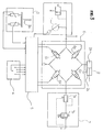
- figure 3 is a hydraulic circuit showing schematically the control apparatus of the present invention.
- FIG 3 shows schematically a control apparatus of hydraulic actuator according to one embodiment of the present invention.
- the control apparatus according to this embodiment comprises a variable displacement pump 1 which is operated by an engine(not shown) and regulates variably a discharge oil amount by controlling the tilt angle of a swash plate by a regulator(not shown), an operation indicator 3 having a joystick lever 3a in order for an operator to select a corresponding hydraulic actuator 2 and the moving direction, an operation mode selector 4 for selecting the required operation mode(manual or automatic), and a controller 5 for generating a control signal in order to supply the required oil amount to the corresponding actuator 2 from said pump 1 according to the operation command signals from said operation indicator 3 and said operation mode selector 4.
- said engine there are installed means for detecting the number of rotation of engine and a pulse generator for generating the pulse signal proportional to the number of rotation of engine, and in the pump 1, a detector for detecting the tilt angle of a swash plate is installed.
- a direction switch 6 for sending the discharge oil amount of the pump 1 to the selected actuator 2 by the control signal of the controller 5 is installed.
- the direction switch 6 forms the loop combining a plurality of the direction control valves connected in series to each other. That is, the 1st direction control valve 6a, the 2nd direction control valve 6b, the 3rd direction control valve 6c and the 4th direction control valve 6d are connected in series to form the loop, and all the direction control valves 6a, 6b, 6c, and 6d are connected electrically to said controller 5.
- the oil paths between the direction control valves 6a, 6b, 6c, and 6d in the loop of said direction swith 6 are connected to the pump 1, a large chamber 2a of the actuator 2, a small chamber 2b of the actuator and an oil amount regulator 7, respectively.
- the oil path between the 1st direction control valve 6a and the 3rd direction control valve 6c is connected to the pump 1, the oil path between the 1st direction control valve 6a and the 2nd direction control valve 6b connected to the large chamber 2a of the actuator 2, the oil path between the 3rd direction control valve 6c and the 4th direction control valve 6d connected to the small chmaber 2b of the actuator 2, and the 2nd direction control valve 6b and the 4th direction control valve 6d connected to the oil amount regulator 7.
- the oil amount regulator 7 consists of an unload valve 7a and a proportional control valve 7b, wherein the unload valve 7a keeps constant the pressure difference of an oil between before and after passing the proportional control valve 7b, allowing the only oil amount proportional to the input to pass through the proportional control valve 7b and return to a tank.
- the controller 5 receives the pulse signal from said pulse generator, the signal from the detector of the tilt angle of swash plate, and the operation command signals from the operation indicator 3 and the operation mode selector 4, and sends the control signals through a predetermined calculation to said direction switch 6, the oil amount regulator 7 and the tilt angle regulator to control the outputs of them.
- the moving direction and speed of each actuator 2 are determined by the operation indicator 3 and the operation mode selector 4.
- the controller 5 calculates the total required oil amount of pump(Qth) and compares this amount with the real discharge oil amount of pump(Qreal). If Qth>Qreal, the oil amount is increased by increasing the tilt angle of swash plate using a regulator. If Qth ⁇ Qreal, the tilt angle of swash plate is controlled to decrease so that the Qth equals to Qreal.
- the controller 5 applies the control signal to the direction switch 6 to operate the corresponding actuator 2.
- the 1st and the 4th direction control valves 6a, 6d are ON(supply oil to large chamber 2a) while the 2nd and the 3rd direction control valves 6b, 6c are OFF
- the 2nd and the 3rd direction control valves (6b, 6c) are ON while the 1st and 4th direction control valves(6a, 6d) are OFF(supply oil to small chamber 2b).
- the present invention not only enables the precise control of actuator by the oil amount regulator irrespective of the load change, but allows the hydraulic system to be made in the simple way for the various applications, since the direction switch and the oil amount regulator are separated from each other and operated independently. Therefore the reduction in the manufacturing cost and the compatibility can be achieved. Furthermore, the free falling due to the self-weight of an actuator can be effectively prevented, since the oil amount regulator is connected in parallel to the actuator.
Applications Claiming Priority (2)
| Application Number | Priority Date | Filing Date | Title |
|---|---|---|---|
| KR9312561 | 1993-07-05 | ||
| KR1019930012561A KR0184512B1 (ko) | 1993-07-05 | 1993-07-05 | 유압작동기의 방향 및 속도 제어장치 |
Publications (2)
| Publication Number | Publication Date |
|---|---|
| EP0637788A1 true EP0637788A1 (de) | 1995-02-08 |
| EP0637788B1 EP0637788B1 (de) | 1997-03-12 |
Family
ID=19358745
Family Applications (1)
| Application Number | Title | Priority Date | Filing Date |
|---|---|---|---|
| EP94110279A Expired - Lifetime EP0637788B1 (de) | 1993-07-05 | 1994-07-01 | Steuereinheit für hydraulischen Stellantrieb |
Country Status (4)
| Country | Link |
|---|---|
| EP (1) | EP0637788B1 (de) |
| JP (1) | JPH0798001A (de) |
| KR (1) | KR0184512B1 (de) |
| DE (1) | DE69402007T2 (de) |
Cited By (5)
| Publication number | Priority date | Publication date | Assignee | Title |
|---|---|---|---|---|
| WO2000073665A1 (fr) * | 1999-05-28 | 2000-12-07 | Shin Caterpillar Mitsubishi Ltd. | Dispositif de soupape et dispositif de commande d'actionneur hydraulique |
| WO2002090780A1 (en) * | 2001-05-02 | 2002-11-14 | Husco International, Inc. | Hydraulic circuit with a return line metering valve and method of operation |
| WO2006130267A1 (en) * | 2005-05-31 | 2006-12-07 | Caterpillar Inc. | Hydraulic system having a return pressure compensator |
| CN113383132A (zh) * | 2019-01-23 | 2021-09-10 | 沃尔沃建筑设备公司 | 用于液压系统的控制单元 |
| CN113530783A (zh) * | 2021-07-19 | 2021-10-22 | 中航力源液压股份有限公司 | 带卸荷功能的两级压力控制装置 |
Citations (3)
| Publication number | Priority date | Publication date | Assignee | Title |
|---|---|---|---|---|
| DE3044515A1 (de) * | 1980-11-26 | 1982-06-03 | bso Steuerungstechnik GmbH, 6603 Sulzbach | Verstelleinrichtung fuer hydraulikpumpe mit verstellbarer foerdermenge |
| EP0275968A2 (de) * | 1987-01-23 | 1988-07-27 | Brueninghaus Hydromatik Gmbh | Steuervorrichtung für ein hydrostatisches Getriebe für wenigstens zwei Verbraucher |
| EP0381328A2 (de) * | 1989-01-31 | 1990-08-08 | Kabushiki Kaisha Kobe Seiko Sho | Ölhydraulikkreis für eine hydraulische Maschine, z.B. einen Löffelbagger |
-
1993
- 1993-07-05 KR KR1019930012561A patent/KR0184512B1/ko not_active IP Right Cessation
-
1994
- 1994-04-28 JP JP6113559A patent/JPH0798001A/ja active Pending
- 1994-07-01 EP EP94110279A patent/EP0637788B1/de not_active Expired - Lifetime
- 1994-07-01 DE DE69402007T patent/DE69402007T2/de not_active Expired - Fee Related
Patent Citations (3)
| Publication number | Priority date | Publication date | Assignee | Title |
|---|---|---|---|---|
| DE3044515A1 (de) * | 1980-11-26 | 1982-06-03 | bso Steuerungstechnik GmbH, 6603 Sulzbach | Verstelleinrichtung fuer hydraulikpumpe mit verstellbarer foerdermenge |
| EP0275968A2 (de) * | 1987-01-23 | 1988-07-27 | Brueninghaus Hydromatik Gmbh | Steuervorrichtung für ein hydrostatisches Getriebe für wenigstens zwei Verbraucher |
| EP0381328A2 (de) * | 1989-01-31 | 1990-08-08 | Kabushiki Kaisha Kobe Seiko Sho | Ölhydraulikkreis für eine hydraulische Maschine, z.B. einen Löffelbagger |
Cited By (9)
| Publication number | Priority date | Publication date | Assignee | Title |
|---|---|---|---|---|
| WO2000073665A1 (fr) * | 1999-05-28 | 2000-12-07 | Shin Caterpillar Mitsubishi Ltd. | Dispositif de soupape et dispositif de commande d'actionneur hydraulique |
| WO2002090780A1 (en) * | 2001-05-02 | 2002-11-14 | Husco International, Inc. | Hydraulic circuit with a return line metering valve and method of operation |
| GB2392258A (en) * | 2001-05-02 | 2004-02-25 | Husco Int Inc | Hydraulic circuit with a return line metering valve and method of operation |
| GB2392258B (en) * | 2001-05-02 | 2004-09-15 | Husco Int Inc | Hydraulic circuit with a return line metering valve and method of operation |
| DE10296739B4 (de) * | 2001-05-02 | 2008-05-08 | Husco International Inc., Waukesha | Hydrauliksystem und Verfahren zum Betreiben eines Hydrauliksystems |
| WO2006130267A1 (en) * | 2005-05-31 | 2006-12-07 | Caterpillar Inc. | Hydraulic system having a return pressure compensator |
| US7302797B2 (en) | 2005-05-31 | 2007-12-04 | Caterpillar Inc. | Hydraulic system having a post-pressure compensator |
| CN113383132A (zh) * | 2019-01-23 | 2021-09-10 | 沃尔沃建筑设备公司 | 用于液压系统的控制单元 |
| CN113530783A (zh) * | 2021-07-19 | 2021-10-22 | 中航力源液压股份有限公司 | 带卸荷功能的两级压力控制装置 |
Also Published As
| Publication number | Publication date |
|---|---|
| DE69402007D1 (de) | 1997-04-17 |
| JPH0798001A (ja) | 1995-04-11 |
| KR0184512B1 (ko) | 1999-04-15 |
| EP0637788B1 (de) | 1997-03-12 |
| KR950003940A (ko) | 1995-02-17 |
| DE69402007T2 (de) | 1997-06-19 |
Similar Documents
| Publication | Publication Date | Title |
|---|---|---|
| KR100436278B1 (ko) | 변속비셀렉터기구 | |
| US5249421A (en) | Hydraulic control apparatus with mode selection | |
| US5261234A (en) | Hydraulic control apparatus | |
| DE69602923T3 (de) | Elektrohydraulische proportionale steuerventilvorrichtung | |
| US7430859B2 (en) | Fluid pump control system for excavators | |
| EP0533958B1 (de) | Hydraulisches antriebssystem für eine baumaschine | |
| US5274557A (en) | Teaching and playback method for work machine | |
| US5682315A (en) | Method and system for controlling a split torque transmission | |
| US5520087A (en) | Control device for hydraulically operated machine | |
| JPH0826552B2 (ja) | 建設機械のポンプ吐出量制御システム | |
| US5398507A (en) | Hydraulic circuit system | |
| EP0670426A1 (de) | Kreislauf zur pumpfördermengenänderung in einem geschlossenem mittellastfühlsystem | |
| EP0637788B1 (de) | Steuereinheit für hydraulischen Stellantrieb | |
| EP1231386A1 (de) | Hydraulische antriebsvorrichtung | |
| US5279122A (en) | Hydraulic circuit apparatus for supplying fluid under pressure into hydraulic cylinders for work implement | |
| EP0111208A1 (de) | Getriebe | |
| EP0439621A1 (de) | Zufuhrschaltungsvorrichtung für öl unter druck zum hydraulischem kolben einer baustellenvorrichtung | |
| JP3003958B2 (ja) | ロードセンシング油圧回路 | |
| US5636119A (en) | Downstream rate limiting method in transmission control | |
| US5088384A (en) | Hydraulic actuator controlled by meter-in valves and variable pressure relief valves | |
| EP0530876B1 (de) | Steuervorrichtung für ein automatisches Getriebe | |
| EP0433454B1 (de) | Hydraulische schaltungsvorrichtung | |
| SU1362674A1 (ru) | Гидравлический автомат управлени и защиты многоступенчатой трансмиссии с электромагнитными клапанами дистанционного переключени ступеней | |
| KR0168991B1 (ko) | 유압식 건설기계의 전자제어장치 | |
| KR970000244B1 (ko) | 가변차압 제어장치 |
Legal Events
| Date | Code | Title | Description |
|---|---|---|---|
| PUAI | Public reference made under article 153(3) epc to a published international application that has entered the european phase |
Free format text: ORIGINAL CODE: 0009012 |
|
| AK | Designated contracting states |
Kind code of ref document: A1 Designated state(s): DE FR GB IT |
|
| 17P | Request for examination filed |
Effective date: 19950207 |
|
| GRAG | Despatch of communication of intention to grant |
Free format text: ORIGINAL CODE: EPIDOS AGRA |
|
| 17Q | First examination report despatched |
Effective date: 19960522 |
|
| GRAH | Despatch of communication of intention to grant a patent |
Free format text: ORIGINAL CODE: EPIDOS IGRA |
|
| GRAH | Despatch of communication of intention to grant a patent |
Free format text: ORIGINAL CODE: EPIDOS IGRA |
|
| GRAA | (expected) grant |
Free format text: ORIGINAL CODE: 0009210 |
|
| AK | Designated contracting states |
Kind code of ref document: B1 Designated state(s): DE FR GB IT |
|
| REF | Corresponds to: |
Ref document number: 69402007 Country of ref document: DE Date of ref document: 19970417 |
|
| ET | Fr: translation filed | ||
| ITF | It: translation for a ep patent filed |
Owner name: MODIANO & ASSOCIATI S.R.L. |
|
| PLBE | No opposition filed within time limit |
Free format text: ORIGINAL CODE: 0009261 |
|
| STAA | Information on the status of an ep patent application or granted ep patent |
Free format text: STATUS: NO OPPOSITION FILED WITHIN TIME LIMIT |
|
| 26N | No opposition filed | ||
| REG | Reference to a national code |
Ref country code: FR Ref legal event code: TP |
|
| REG | Reference to a national code |
Ref country code: GB Ref legal event code: 732E |
|
| PGFP | Annual fee paid to national office [announced via postgrant information from national office to epo] |
Ref country code: DE Payment date: 20010625 Year of fee payment: 8 |
|
| PGFP | Annual fee paid to national office [announced via postgrant information from national office to epo] |
Ref country code: GB Payment date: 20010627 Year of fee payment: 8 |
|
| PGFP | Annual fee paid to national office [announced via postgrant information from national office to epo] |
Ref country code: FR Payment date: 20010712 Year of fee payment: 8 |
|
| REG | Reference to a national code |
Ref country code: GB Ref legal event code: IF02 |
|
| PG25 | Lapsed in a contracting state [announced via postgrant information from national office to epo] |
Ref country code: GB Free format text: LAPSE BECAUSE OF NON-PAYMENT OF DUE FEES Effective date: 20020701 |
|
| PG25 | Lapsed in a contracting state [announced via postgrant information from national office to epo] |
Ref country code: DE Free format text: LAPSE BECAUSE OF NON-PAYMENT OF DUE FEES Effective date: 20030201 |
|
| GBPC | Gb: european patent ceased through non-payment of renewal fee |
Effective date: 20020701 |
|
| PG25 | Lapsed in a contracting state [announced via postgrant information from national office to epo] |
Ref country code: FR Free format text: LAPSE BECAUSE OF NON-PAYMENT OF DUE FEES Effective date: 20030331 |
|
| REG | Reference to a national code |
Ref country code: FR Ref legal event code: ST |
|
| PG25 | Lapsed in a contracting state [announced via postgrant information from national office to epo] |
Ref country code: IT Free format text: LAPSE BECAUSE OF NON-PAYMENT OF DUE FEES;WARNING: LAPSES OF ITALIAN PATENTS WITH EFFECTIVE DATE BEFORE 2007 MAY HAVE OCCURRED AT ANY TIME BEFORE 2007. THE CORRECT EFFECTIVE DATE MAY BE DIFFERENT FROM THE ONE RECORDED. Effective date: 20050701 |