EP0635455B1 - Vorrichtung zum Kontrollieren der Schaumbildung und des Durchflusses in Getränke-Abgabevorrichtungen - Google Patents
Vorrichtung zum Kontrollieren der Schaumbildung und des Durchflusses in Getränke-Abgabevorrichtungen Download PDFInfo
- Publication number
- EP0635455B1 EP0635455B1 EP94305308A EP94305308A EP0635455B1 EP 0635455 B1 EP0635455 B1 EP 0635455B1 EP 94305308 A EP94305308 A EP 94305308A EP 94305308 A EP94305308 A EP 94305308A EP 0635455 B1 EP0635455 B1 EP 0635455B1
- Authority
- EP
- European Patent Office
- Prior art keywords
- beverage
- flow
- flow regulator
- faucet
- operably
- Prior art date
- Legal status (The legal status is an assumption and is not a legal conclusion. Google has not performed a legal analysis and makes no representation as to the accuracy of the status listed.)
- Expired - Lifetime
Links
- 235000013361 beverage Nutrition 0.000 title claims abstract description 78
- 238000005187 foaming Methods 0.000 title claims abstract description 19
- 239000006260 foam Substances 0.000 claims abstract description 13
- 239000007789 gas Substances 0.000 claims description 27
- 239000000463 material Substances 0.000 claims description 15
- 239000012530 fluid Substances 0.000 claims description 10
- 230000007704 transition Effects 0.000 claims description 5
- 238000011144 upstream manufacturing Methods 0.000 claims description 5
- 238000004891 communication Methods 0.000 claims description 4
- 238000003780 insertion Methods 0.000 claims description 3
- 230000037431 insertion Effects 0.000 claims description 3
- 229910001220 stainless steel Inorganic materials 0.000 claims description 3
- 239000010935 stainless steel Substances 0.000 claims description 3
- 235000013405 beer Nutrition 0.000 abstract description 59
- 230000001276 controlling effect Effects 0.000 abstract 1
- 230000001105 regulatory effect Effects 0.000 abstract 1
- CURLTUGMZLYLDI-UHFFFAOYSA-N Carbon dioxide Chemical compound O=C=O CURLTUGMZLYLDI-UHFFFAOYSA-N 0.000 description 24
- 229910002092 carbon dioxide Inorganic materials 0.000 description 12
- 239000001569 carbon dioxide Substances 0.000 description 12
- 239000003380 propellant Substances 0.000 description 8
- 239000007788 liquid Substances 0.000 description 6
- 238000009434 installation Methods 0.000 description 5
- 238000000034 method Methods 0.000 description 5
- LYCAIKOWRPUZTN-UHFFFAOYSA-N Ethylene glycol Chemical compound OCCO LYCAIKOWRPUZTN-UHFFFAOYSA-N 0.000 description 4
- 238000010521 absorption reaction Methods 0.000 description 3
- 239000002826 coolant Substances 0.000 description 3
- 230000000694 effects Effects 0.000 description 3
- 230000008569 process Effects 0.000 description 3
- 230000003466 anti-cipated effect Effects 0.000 description 2
- 238000004140 cleaning Methods 0.000 description 2
- 238000010276 construction Methods 0.000 description 2
- 238000013461 design Methods 0.000 description 2
- WGCNASOHLSPBMP-UHFFFAOYSA-N hydroxyacetaldehyde Natural products OCC=O WGCNASOHLSPBMP-UHFFFAOYSA-N 0.000 description 2
- 238000010079 rubber tapping Methods 0.000 description 2
- 229910000619 316 stainless steel Inorganic materials 0.000 description 1
- 208000032544 Cicatrix Diseases 0.000 description 1
- LFQSCWFLJHTTHZ-UHFFFAOYSA-N Ethanol Chemical compound CCO LFQSCWFLJHTTHZ-UHFFFAOYSA-N 0.000 description 1
- 239000004698 Polyethylene Substances 0.000 description 1
- 229910000589 SAE 304 stainless steel Inorganic materials 0.000 description 1
- 206010039580 Scar Diseases 0.000 description 1
- CDBYLPFSWZWCQE-UHFFFAOYSA-L Sodium Carbonate Chemical compound [Na+].[Na+].[O-]C([O-])=O CDBYLPFSWZWCQE-UHFFFAOYSA-L 0.000 description 1
- 208000027418 Wounds and injury Diseases 0.000 description 1
- 230000002411 adverse Effects 0.000 description 1
- 239000003570 air Substances 0.000 description 1
- 239000012080 ambient air Substances 0.000 description 1
- 238000013459 approach Methods 0.000 description 1
- 230000015572 biosynthetic process Effects 0.000 description 1
- 235000014171 carbonated beverage Nutrition 0.000 description 1
- 230000015556 catabolic process Effects 0.000 description 1
- 239000003518 caustics Substances 0.000 description 1
- 238000001816 cooling Methods 0.000 description 1
- 230000003247 decreasing effect Effects 0.000 description 1
- 230000002950 deficient Effects 0.000 description 1
- 238000006731 degradation reaction Methods 0.000 description 1
- 230000001066 destructive effect Effects 0.000 description 1
- 230000010354 integration Effects 0.000 description 1
- 239000000203 mixture Substances 0.000 description 1
- 238000012986 modification Methods 0.000 description 1
- 230000004048 modification Effects 0.000 description 1
- 230000006911 nucleation Effects 0.000 description 1
- 238000010899 nucleation Methods 0.000 description 1
- 230000000737 periodic effect Effects 0.000 description 1
- 230000002093 peripheral effect Effects 0.000 description 1
- 230000002085 persistent effect Effects 0.000 description 1
- 239000004033 plastic Substances 0.000 description 1
- 229920003023 plastic Polymers 0.000 description 1
- -1 polyethylene Polymers 0.000 description 1
- 229920000573 polyethylene Polymers 0.000 description 1
- 230000001141 propulsive effect Effects 0.000 description 1
- 238000011084 recovery Methods 0.000 description 1
- 230000009467 reduction Effects 0.000 description 1
- 238000005096 rolling process Methods 0.000 description 1
- 208000014745 severe cutaneous adverse reaction Diseases 0.000 description 1
- 230000003068 static effect Effects 0.000 description 1
- 239000002699 waste material Substances 0.000 description 1
Images
Classifications
-
- B—PERFORMING OPERATIONS; TRANSPORTING
- B67—OPENING, CLOSING OR CLEANING BOTTLES, JARS OR SIMILAR CONTAINERS; LIQUID HANDLING
- B67D—DISPENSING, DELIVERING OR TRANSFERRING LIQUIDS, NOT OTHERWISE PROVIDED FOR
- B67D1/00—Apparatus or devices for dispensing beverages on draught
- B67D1/08—Details
- B67D1/12—Flow or pressure control devices or systems, e.g. valves, gas pressure control, level control in storage containers
- B67D1/14—Reducing valves or control taps
- B67D1/1405—Control taps
- B67D1/145—Control taps comprising a valve shutter movable in a direction perpendicular to the valve seat
- B67D1/1466—Control taps comprising a valve shutter movable in a direction perpendicular to the valve seat the valve shutter being opened in a direction opposite to the liquid flow
-
- B—PERFORMING OPERATIONS; TRANSPORTING
- B67—OPENING, CLOSING OR CLEANING BOTTLES, JARS OR SIMILAR CONTAINERS; LIQUID HANDLING
- B67D—DISPENSING, DELIVERING OR TRANSFERRING LIQUIDS, NOT OTHERWISE PROVIDED FOR
- B67D1/00—Apparatus or devices for dispensing beverages on draught
- B67D1/08—Details
- B67D1/0857—Cooling arrangements
- B67D1/0858—Cooling arrangements using compression systems
- B67D1/0861—Cooling arrangements using compression systems the evaporator acting through an intermediate heat transfer means
- B67D1/0865—Cooling arrangements using compression systems the evaporator acting through an intermediate heat transfer means by circulating a cooling fluid along beverage supply lines, e.g. pythons
- B67D1/0867—Cooling arrangements using compression systems the evaporator acting through an intermediate heat transfer means by circulating a cooling fluid along beverage supply lines, e.g. pythons the cooling fluid being a liquid
Definitions
- the present invention relates to beverage dispensing systems, and in particular, to systems for dispensing beverages which contain dissolved gases (e.g., carbonated beverages such as beer or soda), which are stored in kegs, and dispensed from faucets at locations more or less remote from the keg storage location.
- gases e.g., carbonated beverages such as beer or soda
- the beer kegs are stored in a cooler in a basement or back room, vertically and/or horizontally remote from the dispensing location (bar).
- a number of beverage transport tubes extend from the kegs in the cooler to the bar, to a dispensing device to which the faucet or faucets are attached.
- a number of other tubes, carrying a coolant (glycol) are placed in a circuit from the cooler, substantially parallel to the beverage transport tubes, all the way to the faucets, and back to the cooler, so that the beer and the faucets are cooled.
- the two sets of tubes are typically encased together in a temperature isolating enclosure, and the assembly is often referred to as a "python".
- the motive force which causes the beer to flow in such a system is pressurized gas.
- pressurized gas Most relatively small systems utilize carbon dioxide, which is supplied from pressurized cylinders.
- a pressure regulator between the cylinder and the beer kegs, is nominally used to control the amount of pressure applied to the beer.
- a mixture of gases air and carbon dioxide
- Such mixed gases are also used when the pressure required in a carbon dioxide system, just to make the beer move, is so great that gas absorption will take place readily (as described in further detail hereinafter).
- Such mixed gas systems are complex and expensive.
- a typical beer keg is configured so that the tube, through which the beer is withdrawn from the keg, has its opening adjacent the bottom of the keg.
- the pressurizing gas is inletted into the keg through an opening in the top of the keg, so that the pressurizing gas pushes "down" on the beer.
- a beer dispensing set-up once established, will provide the cold beer at a desired flow rate of approximately 0.063 litres per second (one gallon per minute), with the beer leaving the faucet in a continuous, substantially completely liquid state.
- the system In order for a beer to "run” properly, the system must be configured so as to place a certain amount of "back" pressure (that is, resistance pressure) in the lines, when running.
- a typical desired range of back pressure is between 62069 Nm -2 and 165517 Nm -2 (between nine and twenty-four pounds per square inch).
- each beer dispensing installation is an individual set-up, which must be calculated and laid out according to the customer's needs, and the structural limitations (e.g., run length) of the site.
- Foam occurs when the beer is agitated, or when the beer passes quickly through a region of sudden, drastic pressure drop.
- the flow passageway widens suddenly where it joins the valve portion of the faucet. This area is often referred to as the "bellmouth". It is believed that if the beer is under too high a pressure as it approaches the bellmouth, the sudden increase in available volume upon entering the bellmouth so drastically lowers the pressure on the beer that the carbon dioxide which is dissolved in the beer comes out of solution, producing foam. Excess foam is perhaps the leading cause of wasted beer, and thus lost profits, from which a proprietor may suffer.
- the performance of a particular dispensing set-up may also be affected by the brand of beer which is being delivered.
- Some lighter beers are "fragile” and tend to break up into foam even over short distances, due to the pressure required to make them flow at all.
- Low alcohol beers are also difficult to make “run”, that is, flow without foaming, since, by their nature, they do not hold carbon dioxide in solution well.
- the performance of a dispensing set-up may degrade over time as a result of a number of factors.
- the functioning of the cooler in which the kegs are stored may degrade, raising the beer temperature slightly, and increasing its propensity to break up.
- An increase of only 1-11 ⁇ 2 degrees Celsius (2-3 degrees F) insufficient to be otherwise noticed by a consumer, could lead to substantial losses to foaming. Damage to the transportation piping, caused by the application of caustic materials during required periodic cleaning, also can affect the performance of the dispensing system.
- Prior art attempts at providing apparatus for adding back pressure have typically comprised the integration of a flow regulator into the faucet, in the form of a piston, which is axially movable in the direction of the shank of the faucet.
- This piston may be covered with an elastomeric sheath so as present a relatively smooth surface to the beer flow, to prevent the formation of foam.
- the free end of the piston, which points upstream, may be formed as a tapered cylinder, or even as a cone, and will be actuated by a lever on the outside of the faucet. When actuated, the piston will move, so as to obstruct a greater or lesser amount of the flow passageway in the shank, to increase or decrease the effective cross-sectional area of the flow passageway. Faucets incorporating such devices are manufactured or have been manufactured in the past by such firms as Cornelius in Anoka, Minnesota, and Perlick in Milwaukee, Wisconsin.
- European Patent Application No 0285769 discloses apparatus for use in dispensing fluid from a container, wherein a cylindrical housing extends into the volume of fluid in the container from an opening on the side of the container. Inside the housing is located a flow restrictor comprising a substantially cylindrical plug having a peripheral helically extending rib which contacts the inner surface of the housing to define a helical passageway. Holes are provided in the housing wall so that the fluid in the container must flow along the helical passageway before leaving the container via a nozzle. The helical passageway functions to reduce the pressure of the fluid before it leaves the container.
- PCT Patent Application No WO 91/08978 discloses flow control apparatus for reducing the pressure on a liquid as it flows from a container where it is maintained at a relatively high pressure to a dispensing valve where the liquid is dispensed at a relatively low pressure.
- the reduction in the pressure is achieved by passing the liquid through a helically wound coil of tubing.
- an object of the present invention to provide an apparatus for controlling foaming and flowrate in a pressurized beverage dispensing system, such as a beer tapping system.
- Another object of the invention is to provide an apparatus for controlling foaming, while otherwise improving performance of a beer tapping system, by providing additional back pressure to the system to "balance" the overall system.
- a further object of the invention is provide such a foam control apparatus which additionally regulates the flowrate of the beverage being dispensed to additionally control and substantially preclude break up of the beverage during dispensing.
- Still another object of the invention is to provide such a foam control device which may be readily added to a dispensing system, after the system has been originally installed, without requiring substantial disassembly of the system, or causing potentially destructive or disruptive uncovering of enclosed, sealed components of the system.
- Yet still another object of the invention is to provide an apparatus for controlling foaming in beverage dispensing systems which may be readily and inexpensively fabricated and installed.
- a beverage dispensing system for delivering and dispensing beverages having dissolved gases therein, under pressure, which beverages may tend to break up and release said dissolved gases in the form of foam, said beverage dispensing system comprising:
- said substantially cylindrical coil has an outer diameter advantageously configured so as to enable a slightly forced fit, upon insertion of said flow regulator member into said flow passageway of said shank portion of said at least one faucet means.
- said flow regulator member further comprises:
- Said mesh member may be fabricated from food grade stainless steel.
- said mesh member is formed from a substantially rectangular piece of mesh material.
- Said mesh material preferably has a wire thickness of 0.4 mm (0.016 inches).
- Said mesh material may have a square per linear centimetre count in the range of 7 to 8.7 squares per linear centimetre (18 to 22 squares per linear inch).
- the invention also provides an apparatus for substantially precluding foaming in a system for dispensing beverages having gases dissolved therein, in which the dispensing system includes source means for storing said beverage in a controlled environment; at least one beverage transport member, operably associated with said source means, for transporting said beverage, under pressure, away from said source means of beverage; at least one faucet means, operably associated with said at least one beverage transport member, for enabling delivery of said beverage into containers for consumption, said at least one faucet means including shank portion, operably connected in fluid communication with said at least one beverage transport member, for receiving said beverage from said at least one beverage transport member, a valve portion, operably configured to be selectively positionable between open and closed configurations, to start and stop flow of said beverage through said beverage dispensing system, and a nozzle portion, for directing flow of said beverage into said containers, said apparatus comprising:
- said flow regulator means further comprises: handle means, operably emanating from an end of said coil, for facilitating removal of said flow regulator means from said flow passageway, and for substantially precluding overinsertion of said flow regulator means into said flow passageway.
- said handle means comprises:
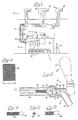
- Fig. 1 depicts, in partial schematic form, a typical beer dispensing set-up 10, which includes storage portion 12, transport portion 14 and delivery portion 16.
- Delivery portion 10 of dispensing set-up 10 includes cooler 18, in which a number of beer kegs 20 are stored. Power plant 22 supplies cooling for the cooler 18, and additionally supplies coolant fluid for transport portion 14, in a manner described below.
- a compressor 28 may be used which mixes the bottled gas with ambient air, which passes through further regulators 26.
- Tubes 30 lead from kegs 20 in a collected bundle (called a "python") in transport portion 14, to their respective faucets 32 in columns 34 in delivery portion 16.
- Delivery portion 16 may be located at a position quite removed from storage portion 12, at a substantial distance both horizontally and vertically. Accordingly, in order to keep the beer cold, palatable, and substantially liquid en route to the faucets, liquid coolant fluid, typically glycol, is transported in pipes 36, 30 to and from faucets 32 immediately adjacent to tubes 30.
- Transport portion or "python" 14 is thermally insulated, so as to prevent tubes 30, and pipes 36 and 38 from absorbing heat along their lengths.
- FIG. 2 A typical beer faucet construction is shown in Fig. 2.
- Faucet 32 which is supported in a column (not shown) in conventional manner, includes shank 40, and combined nozzle and valve portion 42.
- Shank 40 is connected to one of tubes 30 (not shown) in the direction of arrow A.
- Nozzle and valve portion 42 includes nozzle 46, valve member 48 with valve stem 50, head 51 and gasket 52, and lever 54.
- lever 54 When lever 54 is in the position shown in Fig. 2, gasket 52 is held against valve seat 53, and the valve is closed.
- lever 54 is moved in the direction of arrow B, valve stem 50 is pushed in the direction of arrow A, in a conventional manner through an intermediate connection between lever 54 and stem 50 (not shown).
- Gasket 52 "lifts" off of valve seat 53, and flow of beer is enabled. Beer flows through flow passageway 44, along the inner surface 56 of bell-mouth 58, over valve seat 53, and out through nozzle 46.
- kegs 20 Ideally, once dispensing set-up 10 has been installed, and tubes 30, which typically are food-grade polyethylene, are connected to kegs 20, pressure is then applied to the kegs 20.
- the set-up which will be considered is one in which only bottled carbon dioxide is used as the propellant.
- the pressure regulator(s) 26 are set to a specific pressure setting which is typically calculated or estimated during the process of installing the set-up. Typically, this pressure will be in the range of 62069 Nm -2 to 165517 Nm -2 (9 to 24 pounds per square inch).
- the set-up may immediately depart from originally calculated performance. For example, it has been observed that the tubing 30 which carries the beer will begin to expand in diameter, as soon as pressure has been applied. This expansion is believed to continue, although perhaps at a steadily decreasing rate, for so long as the pressure is applied (i.e., continuously). Although the static pressure in the tubes 30 falls off, each time lever 54 is actuated to release beer, simultaneously allowing the tubes 30 to begin to return toward their original diameter, recovery toward the original diameter is not instantaneous, and not complete. Accordingly, the system will be operating, in reality, with tubes 30 having greater diameters, and less back pressure, than designed for. Since many such dispensing systems are installed using general empirical design techniques, or even rough field estimation, trial and error techniques, such tube expansion may not be taken into account in the design and construction process.
- the proprietor or operator of the dispensing set-up will increase the carbon dioxide propellant pressure applied to the kegs 20, which may cause the beer to move too quickly through the tubing 30, particularly from flow passageway 44 into bellmouth 58, where the rapid pressure drop may cause foaming. Furthermore, when the beer is not flowing, the elevated carbon dioxide pressure will cause the beer to absorb the gas, ruining the taste of the beer, and giving the beer even more tendency to foam.
- Figs. 3 - 6 depict the apparatus according to the present invention (also shown in place in Fig. 2), which is intended to be a remedy for foaming problems in beer dispensing set-ups.
- the apparatus comprises a substantially cylindrical coil 60 rolled from a single sheet 62 of mesh material.
- the mesh material is food grade 304 or 316 stainless steel, and may have a wire diameter of about 0.4 mm (0.016 inches), although greater or lesser wire diameters are also possible.
- the mesh material may be a food grade plastic material, so long as the cross-sections of the "wires" of the mesh are round, and not flattened.
- the mesh may have a scares per linear centimetre count of 7 to 8.7 squares per linear centimetre (18 to 22 squares per linear inch).
- a mesh having 7.8 squares per linear centimetre (20 squares per linear inch) is utilized.
- a central passage 64 may or may not be left remaining, depending upon the "length" of sheet 62 prior to rolling.
- sheet 62 may be formed of different lengths, or in an alternative embodiment, may be simply rolled more or less tightly. In this way, the flow control effect may be varied.
- the width dimension "c" in Fig. 3
- the wider sheet 62 is, the longer resultant coil 60 is, and the greater the degree of flow control.
- the width "c" of sheet 62 (the length of coil 60) will range between 19 mm (0.75") and 25 mm (1.00"). If the coil is significantly shorter, there will be insufficient surface area to have enough friction between the outside surface of coil 60 and the inner surface of flow passageway 44 to keep coil 60 properly inserted and in position. A length greater than 25 mm (one inch) may be too large for most applications, and further may provide more added back pressure than would generally be needed. Flow control can also be affected by the mesh size, that is, the number of squares per centimetre (or per inch). A more open mesh will provide a lesser amount of control than a more closed mesh.
- each coil 60 is installed, the system is run, and the quality and quantity of the flow is observed during a timed run.
- proper size coil 60 can be found which will eliminate foaming at the point of exit from the faucet, but which will also permit an acceptable rate of flow, generally within 5% of 0.063 litres per second (within five percent of one gallon per minute).
- the acceptable, non-foaming flowrate must be obtained without excessive applied pressure, which, as previously stated, would have the effect of contaminating the beer with excess absorbed carbon dioxide, when the beer stands, for example, overnight.
- coil 60 in order for coil 60 to function, coil 60 must actually be inserted into flow passageway 44, and not only positioned so as to have an end positioned immediately at the transition point 64 between bellmouth 58 and flow passageway 44. For optimum effect, coil 60 should be completely inserted, as shown in Fig. 2.
- loop 66 is provided, which has an outside diameter which is greater than the diameter of flow passageway 44.
- different shapes of loop 66 may be employed, such as heart-shaped loop 68 (Fig. 6), so as to enable each size and grade of coil 60 to be identified by a unique loop shape.
Landscapes
- Physics & Mathematics (AREA)
- Thermal Sciences (AREA)
- Devices For Dispensing Beverages (AREA)
- Confectionery (AREA)
Claims (16)
- Getränkeabgabevorrichtung (10) zum Befördern und Abgeben von Getränken, die gelöste Gase enthalten, unter Druck, wobei die Getränke dazu neigen können, zu zerfallen und die gelösten Gase als Schaum freizusetzen, wobei die Getränkeabgabevorrichtung aufweist:Aufbewahrungsmittel (12) zum Lagern des Getränks in einer im wesentlichen regulierten Umgebung;mindestens ein mit dem Aufbewahrungsmittel verbindbares Getränketransportelement (30) zum Transportieren des Getränkes unter Druck von dem Aufbewahrungsmittel weg;mindestens ein mit dem mindestens einen Getränketransportelement verbindbares Zapfmittel (32), um die Abgabe des Getränks in Verbrauchsbehälter zu ermöglichen, wobei das mindestens eine Zapfmittel einen Schaftabschnitt (40) umfaßt, der als Flüssigkeitsverbindung an das mindestens eine Getränketransportelement anschließbar ist, um das Getränk von dem mindestens einen Getränketransportelement aufzunehmen, und einen darin angeordneten Strömungsdurchgang aufweist,einen Ventilabschnitt (42), der ausgebildet ist, um wahlweise zwischen offenen und geschlossenen Stellungen positionierbar zu sein, um den Durchfluß des Getränks durch die Getränkeabgabevorrichtung zu beginnen und zu beenden, undein Mundstuck (46), um den Fluß des Getränks in die Behälter zu leiten; undDurchflußregulierungsmittel (60), um das Zerfallen des Getränks und das Freisetzen der gelösten Gase im wesentlichen auszuschließen, um so die Schaumbildung zu verhindern, wobei die Durchflußregulierungsmittel im wesentlichen innerhalb des Schaftabschnittes des mindestens einen Zapfmittels angeordnet werden können,und ein Durchflußregulierungselement (60) enthalten, das stromaufwärts von einer Übergangsstelle zwischen dem Schaftabschnitt und dem Ventilabschnitt des mindestens einen Zapfmittels in den Strömungsdurchgang des Schaftabschnittes einfügbar ist, wobei das Durchflußregulierungselement die Gestalt mindestens einer gewickelten und im wesentlichen zylinderförmigen Spule aufweist.
- Getränkeabgabevorrichtung nach Anspruch 1, dadurch gekennzeichnet, daß die im wesentlichen zylinderförmige Spule einen Außendurchmesser aufweist, der vorteilhafterweise ausgebildet ist, um nach dem Einfügen des Durchflußregulierungselementes in den Strömungsdurchgang des Schaftabschnittes des mindestens einen Zapfmittels einen leichten Preßsitz zu ermöglichen.
- Getränkeabgabevorrichtung nach Anspruch 2, dadurch gekennzeichnet, daß das Durchflußregulierungselement ein Maschenelement (62) aufweist, das vorteilhafterweise ausgebildet ist, um mit einem leichten Preßsitz in den Strömungsdurchgang des Schaftabschnittes des mindestens einen Zapfmittels zu passen.
- Getränkeabgabevorrichtung nach Anspruch 3, dadurch gekennzeichnet, daß das Maschenelement aus lebensmittelechtem rostfreiem Stahl hergestellt ist.
- Getränkeabgabevorrichtung nach Anspruch 3, dadurch gekennzeichnet, daß das Maschenelement aus einem im wesentlichen rechtwinkligen Stuck eines Maschenmaterials ausgebildet ist.
- Getränkeabgabevorrichtung nach Anspruch 5, dadurch gekennzeichnet, daß das Maschenmaterial eine Drahtstärke von 0,4 mm (0,016 inches) aufweist.
- Getränkeabgabevorrichtung nach Anspruch 5, dadurch gekennzeichnet, daß das Maschenmaterial eine Maschenanzahl pro cm in dem Bereich von 7 bis 8,7 Maschen pro cm (18 bis 22 Maschen pro inch) aufweist.
- Vorrichtung (60), um im wesentlichen das Aufschäumen in einer Vorrichtung (10) zur Abgabe von Getränken, die gelöste Gase enthalten, auszuschließen, wobei die Abgabevorrichtung Aufbewahrungsmittel (12) zur Lagerung des Getränks in einer regulierten Umgebung aufweist; mindestens ein Getränketransportelement (30), welches mit dem Aufbewahrungsmittel zum Transportieren des Getränks unter Druck weg von dem Getränkeaufbewahrungsmittel verbindbar ist; mindestens ein Zapfmittel (32), das mit dem mindestens einen Getränketransportelement verbindbar ist, um die Abgabe des Getränks in Verbrauchsbehälter zu ermöglichen, wobei das mindestens eine Zapfmittel einen Schaftabschnitt (40) umfaßt, der als Flüssigkeitsverbindung an das mindestens eine Getränketransportmittel anschließbar ist, um das Getränk von dem mindestens einen Getränketransportelement aufzunehmen, einen Ventilabschnitt (42), der ausgebildet ist, um wahlweise zwischen offenen und geschlossenen Stellungen positionierbar zu sein, um den Durchfluß des Getränks durch die Getränkeabgabevorrichtung zu beginnen und zu beenden, und ein Mundstuck (46), um den Fluß des Getränks in die Behälter zu leiten, wobei die Vorrichtung aufweist:Durchflußregulierungsmittel (60), um das Zerfallen des Getränks und das Freisetzen der gelösten Gase im wesentlichen auszuschließen, um so die Schaumbildung zu verhindern, wobei die Durchflußregulierungsmittel im wesentlichen innerhalb des Schaftabschnittes des mindestens einen Zapfmittels angeordnet werden können,und ein Durchflußregulierungselement enthalten, das stromaufwärts von einer Übergangsstelle zwischen dem Schaftabschnitt und dem Ventilabschnitt des mindestens einen Zapfmittels in den Strömungsdurchgang des Schaftabschnittes einfügbar ist, wobei das Durchflußregulierungselement die Gestalt mindestens einer gewickelten, im wesentlichen zylinderförmigen Spule aufweist.
- Vorrichtung nach Anspruch 8, dadurch gekennzeichnet, daß die im wesentlichen zylinderförmige Spule einen Außendurchmesser aufweist, der vorteilhafterweise ausgebildet ist, um nach dem Einfügen des Durchflußregulierungsmittels in den Strömungsdurchgang des Schaftabschnittes des mindestens einen Zapfmittels einen leichten Preßsitz zu ermöglichen.
- Vorrichtung nach Anspruch 9, dadurch gekennzeichnet, daß das Durchflußregulierungsmittel ein Maschenelement (62) aufweist, das vorteilhafterweise ausgebildet ist, um mit einem leichten Preßsitz in den Strömungsdurchgang des Schaftabschnittes des mindestens einen Zapfmittels zu passen.
- Vorrichtung nach Anspruch 10, dadurch gekennzeichnet, daß das Maschenelement aus lebensmittelechtem rostfreiem Stahl hergestellt ist.
- Vorrichtung nach Anspruch 10, dadurch gekennzeichnet, daß das Maschenelement aus einem im wesentlichen rechtwinkligen Stuck eines Maschenmaterials ausgebildet ist.
- Vorrichtung nach Anspruch 12, dadurch gekennzeichnet, daß das Maschenmaterial eine Drahtstärke von 0,4 mm (0,016 inches) aufweist.
- Vorrichtung nach Anspruch 12, dadurch gekennzeichnet, daß das Maschenmaterial eine Maschenanzahl pro cm in dem Bereich von 7 bis 8,7 Maschen pro cm (18 bis 22 Maschen pro inch) aufweist.
- Vorrichtung nach Anspruch 9, dadurch gekennzeichnet, daß das Durchflußregulierungsmittel Betätigungsmittel (66, 68) aufweist, die von einem Ende der Spule ausgehen, um die Entfernung des Durchflußregulierungsmittels aus dem Strömungsdurchgang zu ermöglichen und das zu tiefe Einfügen des Durchflußregulierungsmittels in den Strömungsdurchgang im wesentlichen auszuschließen.
- Vorrichtung nach Anspruch 15, dadurch gekennzeichnet, daß die Betätigungsmittel ein Drahtschlingenelement (66, 68) aufweisen, das ausgebildet ist, eine aus einer Anzahl von besonderen geometrischen Konturen zu bilden, wobei jede Kontur einer besonderen Kombination von Eigenschaften für ein besonderes Durchflußregulierungsmittel entspricht.
Applications Claiming Priority (2)
| Application Number | Priority Date | Filing Date | Title |
|---|---|---|---|
| US94471 | 1993-07-19 | ||
| US08/094,471 US5368205A (en) | 1993-07-19 | 1993-07-19 | Apparatus for controlling foaming and flowrate in beverage dispensing systems |
Publications (2)
| Publication Number | Publication Date |
|---|---|
| EP0635455A1 EP0635455A1 (de) | 1995-01-25 |
| EP0635455B1 true EP0635455B1 (de) | 1997-05-07 |
Family
ID=22245384
Family Applications (1)
| Application Number | Title | Priority Date | Filing Date |
|---|---|---|---|
| EP94305308A Expired - Lifetime EP0635455B1 (de) | 1993-07-19 | 1994-07-19 | Vorrichtung zum Kontrollieren der Schaumbildung und des Durchflusses in Getränke-Abgabevorrichtungen |
Country Status (5)
| Country | Link |
|---|---|
| US (2) | US5368205A (de) |
| EP (1) | EP0635455B1 (de) |
| AT (1) | ATE152698T1 (de) |
| CA (1) | CA2128260C (de) |
| DE (1) | DE69403030T2 (de) |
Families Citing this family (41)
| Publication number | Priority date | Publication date | Assignee | Title |
|---|---|---|---|---|
| US5368205A (en) * | 1993-07-19 | 1994-11-29 | Banner Beverage Systems, Inc. | Apparatus for controlling foaming and flowrate in beverage dispensing systems |
| US5630529A (en) * | 1995-06-26 | 1997-05-20 | Chlupp; Christopher F. | Piercing tap and method of use therefor |
| WO1997021625A1 (en) * | 1995-12-08 | 1997-06-19 | Vassingerød Metalstøberi A/S | Taphane |
| US5794823A (en) * | 1996-07-31 | 1998-08-18 | Stainless One Dispensing Systems | Limited action flow control fluid dispenser |
| US5813574A (en) * | 1996-10-18 | 1998-09-29 | Mcnabb; Rex P. | Frozen beverage dispensing apparatus |
| FR2792511B1 (fr) * | 1999-04-23 | 2001-06-08 | Beaute Prestige Internat | Appareil de vaporisation a pompe inversee |
| US6247614B1 (en) | 1999-07-15 | 2001-06-19 | Quoin Industrial, Inc. | Method and apparatus for dispensing a liquid containing gas in solution |
| US6449970B1 (en) | 1999-11-10 | 2002-09-17 | Shurflo Pump Manufacturing Company, Inc. | Refrigeration apparatus and method for a fluid dispensing device |
| US6354342B1 (en) | 1999-11-10 | 2002-03-12 | Shurflo Pump Manufacturing Company, Inc. | Hand-held rapid dispensing apparatus and method |
| US6360556B1 (en) | 1999-11-10 | 2002-03-26 | Shurflo Pump Manufacturing Company, Inc. | Apparatus and method for controlling fluid delivery temperature in a dispensing apparatus |
| US6354341B1 (en) | 1999-11-10 | 2002-03-12 | Shurflo Pump Manufacturing Co., Inc. | Rapid comestible fluid dispensing apparatus and method |
| US6443335B1 (en) * | 1999-11-10 | 2002-09-03 | Shurflo Pump Manufacturing Company, Inc. | Rapid comestible fluid dispensing apparatus and method employing a diffuser |
| GB2349379B (en) * | 2000-03-10 | 2001-03-14 | Scottish & Newcastle Plc | Improvements in or relating to a dispensing apparatus |
| NL1015368C2 (nl) * | 2000-05-31 | 2001-12-12 | Heineken Tech Services | Drankafgiftesamenstel alsmede houder voor drank, in het bijzonder koolzuurhoudende drank, en drankafgifteleiding voor toepassing in een dergelijk samenstel. |
| GB2373198B (en) * | 2001-03-14 | 2004-09-08 | Brandbrew Sa | Liquid dispenser with restriction and flow straightener |
| US6968983B2 (en) * | 2002-02-12 | 2005-11-29 | Rodney Laible | Closed loop dispensing system |
| US7278454B2 (en) * | 2003-03-13 | 2007-10-09 | Laminar Technologies, Llc | Beverage dispensing apparatus |
| US20060032869A1 (en) * | 2003-03-13 | 2006-02-16 | Laminar Technologies, Llc | Beverage dispensing apparatus |
| US7178699B2 (en) * | 2003-10-02 | 2007-02-20 | Anheuser-Busch, Inc. | Pinch faucet |
| ITRN20050022A1 (it) * | 2005-03-31 | 2006-10-01 | Celli Spa | Dispositivo di dispensazione liquidi |
| CN101401048B (zh) | 2005-12-15 | 2010-12-01 | 尼亚加拉分装技术股份有限公司 | 饮料分配 |
| EP1969265B1 (de) | 2005-12-15 | 2015-09-16 | DD Operations Ltd. | Digitale durchflussregelung |
| NL1032098C2 (nl) * | 2006-06-30 | 2008-01-02 | Heineken Supply Chain Bv | Tapinrichting, drankcontainer, koppelingsinrichting en werkwijze met reinigingselement. |
| US7823411B2 (en) | 2006-12-15 | 2010-11-02 | Niagara Dispensing Technologies, Inc. | Beverage cooling system |
| US8464903B2 (en) * | 2007-07-09 | 2013-06-18 | Tempak International Pty Ltd | Method for dispensing iced beverages |
| TWM359996U (en) * | 2008-12-22 | 2009-07-01 | song-shan Zhangjian | Juice extractor structure |
| US8360404B2 (en) * | 2009-03-09 | 2013-01-29 | FYCM Enterprises, LLC | Shock absorbing interposer |
| US8083107B2 (en) * | 2009-04-09 | 2011-12-27 | Rodney Laible | Closed loop dispensing system with mechanical venting means |
| EP2336077A1 (de) | 2009-12-18 | 2011-06-22 | Anheuser-Busch InBev S.A. | Getränkeausgabevorrichtung mit integriertem Druckminderungskanal |
| EP2339421A1 (de) | 2009-12-18 | 2011-06-29 | Anheuser-Busch InBev S.A. | Druckregelventil für druckbetriebene Getränkeausgabevorrichtungen |
| US8746506B2 (en) | 2011-05-26 | 2014-06-10 | Pepsico, Inc. | Multi-tower modular dispensing system |
| US8985396B2 (en) | 2011-05-26 | 2015-03-24 | Pepsico. Inc. | Modular dispensing system |
| EP2657186A1 (de) | 2012-04-26 | 2013-10-30 | Anheuser-Busch InBev S.A. | Flüssigkeitsdruckverringerungseinheit für eine Getränkeausgabeeinheit |
| US8708203B2 (en) | 2012-05-07 | 2014-04-29 | Rl Innovations, Llc | Screw-on throat plug assembly |
| US20140263433A1 (en) * | 2013-03-15 | 2014-09-18 | Heineken Uk Limited | Beverage Dispense System and Method |
| US10144630B1 (en) * | 2015-04-06 | 2018-12-04 | Steven P. Keeling | Beverage dispensing system |
| US10703620B1 (en) | 2015-04-06 | 2020-07-07 | Steven P. Keeling | Beverage dispensing system |
| US9745187B2 (en) | 2015-05-05 | 2017-08-29 | Fizzics Group Llc | Carbonated fluid dispenser with ultrasonic foaming mechanism |
| US9895667B2 (en) | 2015-05-05 | 2018-02-20 | Fizzics Group Llc | Carbonated fluid dispenser with ultrasonic foaming mechanism |
| JP7091015B2 (ja) * | 2015-12-01 | 2022-06-27 | ホシザキ株式会社 | 炭酸水注出バルブ |
| WO2021191774A1 (en) * | 2020-03-22 | 2021-09-30 | Cylzer S.A. | Beverage dispenser, beverage dispensing nozzle, and beverage dispensing method |
Citations (1)
| Publication number | Priority date | Publication date | Assignee | Title |
|---|---|---|---|---|
| WO1991008978A1 (en) * | 1989-12-14 | 1991-06-27 | Adolph Coors Company | Flow control apparatus |
Family Cites Families (23)
| Publication number | Priority date | Publication date | Assignee | Title |
|---|---|---|---|---|
| US2924238A (en) * | 1960-02-09 | Foam control device in liquid dispensing apparatus | ||
| US2899170A (en) * | 1959-08-11 | Liquid dispensing apparatus | ||
| US2055096A (en) * | 1932-10-17 | 1936-09-22 | William M Dehn | Infusion apparatus |
| US2091042A (en) * | 1935-02-16 | 1937-08-24 | Edward G Hedges | Effervescent liquid dispensing device |
| US2284135A (en) * | 1939-08-25 | 1942-05-26 | Richard T Cornelius | Beer dispensing system |
| US2331834A (en) * | 1940-08-01 | 1943-10-12 | Herman H Harr | Tap tube |
| US2345840A (en) * | 1941-06-06 | 1944-04-04 | Strong Mfg Company | Beverage dispensing apparatus |
| US2401914A (en) * | 1942-10-17 | 1946-06-11 | Pietro Carmelo V Di | Mixing faucet |
| US2746641A (en) * | 1950-05-27 | 1956-05-22 | Rowe Spacarb Inc | Beverage dispensing machines |
| US2789654A (en) * | 1954-06-07 | 1957-04-23 | Zurit David | Apparatus for filtering air or gas that enters beer kegs |
| FR1167837A (fr) * | 1955-12-02 | 1958-12-01 | Gaskell & Chambers Ltd | Robinet pour commander la distribution de liquides sous pression |
| US3084718A (en) * | 1958-01-23 | 1963-04-09 | Guinness Son & Co Ltd A | Perforated disc restrictor means for use in dispensing fermented liquors |
| US3502111A (en) * | 1965-10-14 | 1970-03-24 | Hansen Mfg | Dispensing device |
| US3373937A (en) * | 1966-04-11 | 1968-03-19 | Bastian Blessing Co | Carbonated water dispensing nozzle |
| US3625399A (en) * | 1969-02-03 | 1971-12-07 | Schlitz Brewing Co J | Automatic carbonated beverage dispensing system |
| US4122978A (en) * | 1975-06-18 | 1978-10-31 | The Gillette Company | Pressurized package for dispensing a product in a finely dispersed spray pattern with little dilution by propellant |
| US4142652A (en) * | 1977-09-02 | 1979-03-06 | Warner-Lambert Company | Aerosol metering |
| US4225060A (en) * | 1978-12-29 | 1980-09-30 | Security Plastics, Inc. | Continuous pumping system |
| US4402485A (en) * | 1981-06-11 | 1983-09-06 | Fisher Controls Company, Inc. | Eccentrically nested tube gas line silencer |
| US4456033A (en) * | 1981-10-09 | 1984-06-26 | Vacco Industries | Perforated sheet stock flow restrictor |
| US4739901A (en) * | 1985-05-20 | 1988-04-26 | Adolph Coors Company | Apparatus for use in dispensing fluid from a container |
| DE3707128A1 (de) * | 1987-03-05 | 1988-09-15 | Knopf Karl Horst | Druckkompensator fuer stark kohlensaeurehaltige getraenke |
| US5368205A (en) * | 1993-07-19 | 1994-11-29 | Banner Beverage Systems, Inc. | Apparatus for controlling foaming and flowrate in beverage dispensing systems |
-
1993
- 1993-07-19 US US08/094,471 patent/US5368205A/en not_active Expired - Lifetime
-
1994
- 1994-07-18 CA CA002128260A patent/CA2128260C/en not_active Expired - Fee Related
- 1994-07-19 DE DE69403030T patent/DE69403030T2/de not_active Expired - Fee Related
- 1994-07-19 AT AT94305308T patent/ATE152698T1/de active
- 1994-07-19 EP EP94305308A patent/EP0635455B1/de not_active Expired - Lifetime
- 1994-09-07 US US08/301,850 patent/US5573145A/en not_active Expired - Lifetime
Patent Citations (1)
| Publication number | Priority date | Publication date | Assignee | Title |
|---|---|---|---|---|
| WO1991008978A1 (en) * | 1989-12-14 | 1991-06-27 | Adolph Coors Company | Flow control apparatus |
Also Published As
| Publication number | Publication date |
|---|---|
| US5368205A (en) | 1994-11-29 |
| CA2128260A1 (en) | 1995-01-20 |
| ATE152698T1 (de) | 1997-05-15 |
| US5573145A (en) | 1996-11-12 |
| DE69403030T2 (de) | 1997-12-11 |
| EP0635455A1 (de) | 1995-01-25 |
| DE69403030D1 (de) | 1997-06-12 |
| CA2128260C (en) | 2002-07-16 |
Similar Documents
| Publication | Publication Date | Title |
|---|---|---|
| EP0635455B1 (de) | Vorrichtung zum Kontrollieren der Schaumbildung und des Durchflusses in Getränke-Abgabevorrichtungen | |
| US8464903B2 (en) | Method for dispensing iced beverages | |
| GB2327748A (en) | Cooling apparatus | |
| EP2207746A2 (de) | Systeme und verfahren zum kühlen und abgeben eines getränks | |
| US20120186782A1 (en) | Beer chilling device | |
| EP1222140B1 (de) | Flüssigkeit abgabevorrichtung mit integrietem wärmeaustauscher | |
| AU2009203886B2 (en) | Improvements in heat exchangers for dispensing sub-zero beer | |
| US20060137383A1 (en) | Inline booster for beverage dispensing system | |
| US20020011076A1 (en) | Beverage cooler | |
| US6637224B2 (en) | Beverage cooler | |
| JP2003513860A (ja) | 高速食用流体供給装置及び方法 | |
| EP1690825A2 (de) | Getränkespender | |
| EP1786721B1 (de) | Ausgabevorrichtung für gekühlte getränke mit einer gekühlten zapfleitung und zusätzlichem kühler | |
| AU2005271004B2 (en) | Apparatus for dispensing chilled beverages | |
| JP5670658B2 (ja) | 飲料ディスペンサ | |
| JP2002534256A (ja) | 炭酸ガス飽和器用の二酸化炭素の予冷却装置 | |
| GB2362204A (en) | Cask beer dispensing apparatus | |
| GB2417065A (en) | Apparatus for dispensing beverages | |
| GB2426753A (en) | Apparatus for cooling and dispensing beverages comprising a housing cooled to form condensation or ice on its exterior surface | |
| GB2438740A (en) | Fluid Cooled Beverage Cooling Module and means to Control Coolant for Consistent Beverage Dispensing Temperature | |
| WO2006016177A2 (en) | Cooled beverage dispenser with a python and an additional chiller | |
| GB2369669A (en) | A circulation system for passing alcoholic beverages from a container to a bar | |
| AU2002100324A4 (en) | Beverage dispensing pump system | |
| CA2772456A1 (en) | Beer chilling device |
Legal Events
| Date | Code | Title | Description |
|---|---|---|---|
| PUAI | Public reference made under article 153(3) epc to a published international application that has entered the european phase |
Free format text: ORIGINAL CODE: 0009012 |
|
| AK | Designated contracting states |
Kind code of ref document: A1 Designated state(s): AT BE DE DK FR GB IE IT |
|
| 17P | Request for examination filed |
Effective date: 19950724 |
|
| 17Q | First examination report despatched |
Effective date: 19950922 |
|
| GRAG | Despatch of communication of intention to grant |
Free format text: ORIGINAL CODE: EPIDOS AGRA |
|
| GRAH | Despatch of communication of intention to grant a patent |
Free format text: ORIGINAL CODE: EPIDOS IGRA |
|
| GRAH | Despatch of communication of intention to grant a patent |
Free format text: ORIGINAL CODE: EPIDOS IGRA |
|
| GRAA | (expected) grant |
Free format text: ORIGINAL CODE: 0009210 |
|
| AK | Designated contracting states |
Kind code of ref document: B1 Designated state(s): AT BE DE DK FR GB IE IT |
|
| PG25 | Lapsed in a contracting state [announced via postgrant information from national office to epo] |
Ref country code: IT Free format text: LAPSE BECAUSE OF FAILURE TO SUBMIT A TRANSLATION OF THE DESCRIPTION OR TO PAY THE FEE WITHIN THE PRE;WARNING: LAPSES OF ITALIAN PATENTS WITH EFFECTIVE DATE BEFORE 2007 MAY HAVE OCCURRED AT ANY TIME BEFORE 2007. THE CORRECT EFFECTIVE DATE MAY BE DIFFERENT FROM THE ONE RECORDED.SCRIBED TIME-LIMIT Effective date: 19970507 Ref country code: FR Effective date: 19970507 Ref country code: DK Effective date: 19970507 Ref country code: BE Effective date: 19970507 Ref country code: AT Effective date: 19970507 |
|
| REF | Corresponds to: |
Ref document number: 152698 Country of ref document: AT Date of ref document: 19970515 Kind code of ref document: T |
|
| REF | Corresponds to: |
Ref document number: 69403030 Country of ref document: DE Date of ref document: 19970612 |
|
| REG | Reference to a national code |
Ref country code: IE Ref legal event code: FG4D Free format text: 73805 |
|
| EN | Fr: translation not filed | ||
| PLBE | No opposition filed within time limit |
Free format text: ORIGINAL CODE: 0009261 |
|
| STAA | Information on the status of an ep patent application or granted ep patent |
Free format text: STATUS: NO OPPOSITION FILED WITHIN TIME LIMIT |
|
| 26N | No opposition filed | ||
| REG | Reference to a national code |
Ref country code: GB Ref legal event code: IF02 |
|
| PGFP | Annual fee paid to national office [announced via postgrant information from national office to epo] |
Ref country code: DE Payment date: 20060714 Year of fee payment: 13 |
|
| PGFP | Annual fee paid to national office [announced via postgrant information from national office to epo] |
Ref country code: GB Payment date: 20060720 Year of fee payment: 13 |
|
| PGFP | Annual fee paid to national office [announced via postgrant information from national office to epo] |
Ref country code: IE Payment date: 20060725 Year of fee payment: 13 |
|
| GBPC | Gb: european patent ceased through non-payment of renewal fee |
Effective date: 20070719 |
|
| PG25 | Lapsed in a contracting state [announced via postgrant information from national office to epo] |
Ref country code: DE Free format text: LAPSE BECAUSE OF NON-PAYMENT OF DUE FEES Effective date: 20080201 |
|
| REG | Reference to a national code |
Ref country code: IE Ref legal event code: MM4A |
|
| PG25 | Lapsed in a contracting state [announced via postgrant information from national office to epo] |
Ref country code: GB Free format text: LAPSE BECAUSE OF NON-PAYMENT OF DUE FEES Effective date: 20070719 |
|
| PG25 | Lapsed in a contracting state [announced via postgrant information from national office to epo] |
Ref country code: IE Free format text: LAPSE BECAUSE OF NON-PAYMENT OF DUE FEES Effective date: 20070719 |