EP0635397B1 - Lastträger für ein Kraftfahrzeug - Google Patents
Lastträger für ein Kraftfahrzeug Download PDFInfo
- Publication number
- EP0635397B1 EP0635397B1 EP94401684A EP94401684A EP0635397B1 EP 0635397 B1 EP0635397 B1 EP 0635397B1 EP 94401684 A EP94401684 A EP 94401684A EP 94401684 A EP94401684 A EP 94401684A EP 0635397 B1 EP0635397 B1 EP 0635397B1
- Authority
- EP
- European Patent Office
- Prior art keywords
- rollers
- luggage rack
- lever
- rails
- rack according
- Prior art date
- Legal status (The legal status is an assumption and is not a legal conclusion. Google has not performed a legal analysis and makes no representation as to the accuracy of the status listed.)
- Expired - Lifetime
Links
- 230000000903 blocking effect Effects 0.000 description 6
- 238000010586 diagram Methods 0.000 description 3
- 238000007373 indentation Methods 0.000 description 3
- 230000000717 retained effect Effects 0.000 description 3
- 239000002184 metal Substances 0.000 description 2
- 241000287107 Passer Species 0.000 description 1
- 239000000969 carrier Substances 0.000 description 1
- 239000002131 composite material Substances 0.000 description 1
- 238000010276 construction Methods 0.000 description 1
- 230000000994 depressogenic effect Effects 0.000 description 1
- 229940082150 encore Drugs 0.000 description 1
- 229910001234 light alloy Inorganic materials 0.000 description 1
- 238000004519 manufacturing process Methods 0.000 description 1
- 239000000463 material Substances 0.000 description 1
- 238000005192 partition Methods 0.000 description 1
- 238000003825 pressing Methods 0.000 description 1
- 230000001681 protective effect Effects 0.000 description 1
- 238000003892 spreading Methods 0.000 description 1
- 238000003860 storage Methods 0.000 description 1
Images
Classifications
-
- B—PERFORMING OPERATIONS; TRANSPORTING
- B60—VEHICLES IN GENERAL
- B60R—VEHICLES, VEHICLE FITTINGS, OR VEHICLE PARTS, NOT OTHERWISE PROVIDED FOR
- B60R9/00—Supplementary fittings on vehicle exterior for carrying loads, e.g. luggage, sports gear or the like
- B60R9/04—Carriers associated with vehicle roof
- B60R9/045—Carriers being adjustable or transformable, e.g. expansible, collapsible
-
- B—PERFORMING OPERATIONS; TRANSPORTING
- B60—VEHICLES IN GENERAL
- B60R—VEHICLES, VEHICLE FITTINGS, OR VEHICLE PARTS, NOT OTHERWISE PROVIDED FOR
- B60R9/00—Supplementary fittings on vehicle exterior for carrying loads, e.g. luggage, sports gear or the like
- B60R9/04—Carriers associated with vehicle roof
- B60R9/05—Carriers characterised by wind deflecting means
Definitions
- the present invention relates to luggage racks for a motor vehicle, comprising two rails intended to be fixed flat on the body of a vehicle and at least one (and in general at least two) sleepers whose ends are formed so as to be able slide on the rails and be locked there.
- the present invention aims in particular to provide a luggage rack whose locking mechanism simultaneously ensures effective blocking and allows easy sliding of the cross member along the rails, requiring only simple blocking and unblocking maneuvers.
- the invention proposes in particular a luggage rack in accordance with claim 1.
- the luggage carrier comprises two crosspieces
- the latter advantageously have facing faces which can be applied directly against each other over almost their entire length, so that the crosspieces then constitute a single fin.
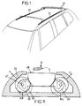
- the luggage rack the general structure of which is shown in FIG. 1, comprises two rails 10 fixed flat, for example by screws, on the roof of a motor vehicle and two cross members 12 intended to support loads. These sleepers are movable along the rails 10. They are shown in phantom in a position where they are spaced from one another and allow to fix loads. They are represented in solid lines in a position where they will generally be placed outside periods of use and are joined.
- each cross member has an asymmetrical constitution.
- the face of each cross member intended to be applied against the other cross member is substantially flat and orthogonal to the rails.
- These two crosspieces generally have an identical structure.
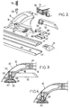
- Each crosspiece has an inverted U shape. As shown in FIG. 2, it can be considered as consisting of a horizontal or slightly curved hollow bar 14 formed by a metal profile, for example made of light alloy, and two feet 16. Each foot comprises a base 18, for example made of molded metal, having a stump 20 for fitting the bar. This base is intended to rest on one of the rails 10.
- the crosspiece is completed by protective covers. A cover 42 covers the base. Another cover 44 covers and protects the bar. It can have a shape improving the aerodynamics of the cross member. The covers can be retained by interlocking and / or by removable means, such as screws.
- the rail 10 is composite in the embodiment shown. It consists of an elongated sole 22 rigidly and permanently fixed to the roof of the vehicle, for example by regularly distributed screws and a spar 24 retained between the folded sides of the sole 22.
- the upper face of the spar constitutes a bearing face for the base 18 of the foot 16.
- the rail can be closed by end pieces 29.
- the base 18 comprises two tenons 45 projecting downwards, passing through the slot in the spar and having a T-shaped cross section, the crossbar of which can be applied against the edges of the groove.
- each base of the foot may have one or more pins projecting downward, intended to engage in one of the housings of a rack fixed to the bottom.
- the spacing of the housings is then provided so that the crosspieces can be locked in positions where they are practically in contact with one another.
- the crosspiece is immobilized by wedging rollers 46, between the bottom and the sides of the beam 24, which define a groove with a flared section downwards.
- a manual locking and unlocking mechanism comprises two locking rollers 46, having extensions 47, trapped in the groove of the side member 24 and placed between the tenons.
- the mechanism further comprises means for spreading the rollers and wedging them against the sides and the bottom of the spar.
- These means comprise a blocking pad 48 having two end flanges 49 which longitudinally retain the rollers 46, locally having a body 51 with a semi-cylindrical profile of action on the rollers.
- the shoe 48 is coupled, for example by a notched washer 52, with an axis 50 pushed down by a spring 54 which is supported on a partition of the base.
- the manual locking and unlocking member is constituted by a lever 56 which can rotate 90 ° between a position where it is retracted in the thickness of the base (FIG. 4) and a position where it is parallel to the crosspiece (FIG. 3 ).
- the lever 56 rotates the square head of the axis 50 which passes through it.
- Means are provided so that the lever 56 lifts by driving the axis 50 when it passes from the position of FIG. 4 to the position of FIG. 3.
- these means include a rib 58 of the lever 56 which is housed in a correspondingly shaped groove 60 of the base when the lever is in the locked position. The exit of the groove during rotation causes the lever to be raised by a sufficient height to loosen the rollers 46 and to stop the support of the pins against the edges of the slot.
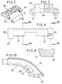
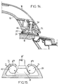
- the shoe 48 has only been shown diagrammatically in FIGS. 2 to 4. A possible construction of this shoe 48 and the rollers 46 is given in FIGS. 5 to 9.
- One of the end plates 49 has two windows 61 for receiving the terminal extensions 47 located on one side of the rollers 46.
- the other flange 49 has blind indentations 63 opening outwards so as to allow the other extensions of the rollers to be engaged therein.
- the body 51 is made up of two fractions on either side of the median plane.
- Unlocking is carried out by bringing the lever 56 into the position where it is shown in FIG. 3.
- the rollers can then come, relative to the shoe in the position where they are shown in dashed lines in FIG. 9. Their jamming ceases.
- the bar can then be moved longitudinally.
- the coefficient of friction of the rollers on the side member 24 is low enough that one can move a bar from one side of the vehicle, which allows one person to perform the position adjustment.
- the rollers are in fact generally made of plastic although other materials can be used.
- FIG. 10 shows a possible arrangement of such indentations 70 and 72.
- the indentation 72 being on the internal side, it is not covered by a possible truss at the bottom of the cross member 74.
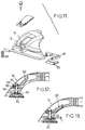
- the locking mechanism shown in FIGS. 11 to 13 also comprises tenons integral with the base 18 of the base (which can for example be molded onto the main part of the base), blocking rollers 46 and a blocking pad 48.
- This pad is subject under the pressure of a spring 54 which tends to press it on the rollers and to wedge the rollers, and also to lift the pins trapped in the groove.
- the manual unlocking member is this time constituted by a lever 62 which can tilt on the base between a locking position, where it is in abutment against a rim of the base (FIG. 13), and a depressed unlocking position (FIG. 12) .
- the lever 62 is coupled to the shoe by a rod 64 comprising a terminal bearing ball 65 on the lever.
- moving the bar requires two operators, each of which unlocks one of the feet and moves it. As the foot locks again as soon as the lever is released and returns to the position shown in FIG. 13, the risk that a shoe remains unlocked is eliminated.
- FIGS. 14 and 15 While the embodiments of the locking mechanism described so far cause the rollers to jam by the action of a force directed downwards, the embodiment shown diagrammatically in FIGS. 14 and 15 has an action in the opposite direction.
- the spring 54 exerts a directed force F upwards, which generates forces F1 and F2 pressing the rollers 46, in channels 76 facing downwards.
- the shoe 48 then has a shape opposite to that used in the previous embodiments.
Landscapes
- Engineering & Computer Science (AREA)
- Mechanical Engineering (AREA)
- Fittings On The Vehicle Exterior For Carrying Loads, And Devices For Holding Or Mounting Articles (AREA)
- Transition And Organic Metals Composition Catalysts For Addition Polymerization (AREA)
- Control Of Direct Current Motors (AREA)
- Vehicle Step Arrangements And Article Storage (AREA)
Claims (6)
- Lastträger für ein Kraftfahrzeug, umfassend:Zwei Schienen (10), die zur flachen Befestigung auf der Karosserie eines Fahrzeuges bestimmt sind, wobei jede Schiene einen Längsträger umfaßt, der eine Nut aufweist, die sich über ein Fenster nach oben öffnet;zumindest eine Traverse (12), die zwei Füße an den Enden (16) umfaßt, die so ausgebildet sind, daß sie in den Schienen gleiten können und jeweils mit einem Mechanismus zur Verriegelung in den Schienen ausgestattet sind;dadurch gekennzeichnet, daß dieser Mechanismus zwei Rollen (46) umfaßt, die in einer Nut gefangen sind, welche durch die divergierenden Flanken der jeweiligen Schiene definiert ist, die in einer ersten Position der Betätigungseinrichtung gegen die Flanken geklemmt sind, sowie freigesetzt in einer zweiten Position.
- Lastträger nach Anspruch 1, dadurch gekennzeichnet, daß die Betätigungseinrichtung aus einem Hebel (56) besteht, der sich um eine Achse rechtwinklig zum Langsträger (24) um einen Fußsockel (16) drehen kann, zwischen einer ersten Position, in der er durch ein Auflager über den Sockel angehoben ist und eine Klemmkufe der gegen die nach unten divergierenden Flanken liegenden Rollen anhebt, entgegen der Wirkung von elastischen Einrichtungen (54), und einer zweiten Position, wo er den elastischen Einrichtungen erlaubt, die Kufe (48) einzudrücken und die Rollen festzuklemmen.
- Lastträger nach Anspruch 1, dadurch gekennzeichnet, daß die Betätigungseinrichtung aus einem Hebel (62) besteht, der an eine Kufe (48) zur Blockade der Rollen angehängt ist, und der manuell um eine Achse parallel zur Schiene kippbar ist, entgegen der Wirkung von elastischen Einrichtungen, aus einer Position, in der die elastischen Einrichtungen ein Verklemmen der Rollen (46) provozieren, in eine Position, in der die Kufe (48) die Rollen freisetzt.
- Lastträger nach Anspruch 2 oder 3, dadurch gekennzeichnet, daß der Hebel so plaziert ist, daß er in den Maßen des Fußes verschwindet, wenn er in Verriegelungsposition ist.
- Lastträger nach einem der vorhergehenden Ansprüche, dadurch gekennzeichnet, daß derjenige Teil einer jeden Traverse, der in der Nähe der Füße angeordnet ist, einen Holm bildet, in den die Füße, umgeben von einer Verkleidung (44), eingepaßt sind.
- Lastträger nach einem der vorhergehenden Ansprüche, dadurch gekennzeichnet, daß er zwei der genannten Traversen (12) umfaßt, die einander zugewandte Seiten aufweisen, die direkt aufeinander zu liegen kommen können, zumindest über den größten Teil ihrer Länge, so daß die Traversen einen einzigen Flügel bilden.
Applications Claiming Priority (2)
| Application Number | Priority Date | Filing Date | Title |
|---|---|---|---|
| FR9309047 | 1993-07-22 | ||
| FR9309047A FR2707938B1 (fr) | 1993-07-22 | 1993-07-22 | Porte-bagages pour véhicule automobile. |
Publications (2)
| Publication Number | Publication Date |
|---|---|
| EP0635397A1 EP0635397A1 (de) | 1995-01-25 |
| EP0635397B1 true EP0635397B1 (de) | 1997-05-21 |
Family
ID=9449524
Family Applications (1)
| Application Number | Title | Priority Date | Filing Date |
|---|---|---|---|
| EP94401684A Expired - Lifetime EP0635397B1 (de) | 1993-07-22 | 1994-07-21 | Lastträger für ein Kraftfahrzeug |
Country Status (6)
| Country | Link |
|---|---|
| US (1) | US5553761A (de) |
| EP (1) | EP0635397B1 (de) |
| AT (1) | ATE153288T1 (de) |
| DE (1) | DE69403284T2 (de) |
| ES (1) | ES2102789T3 (de) |
| FR (1) | FR2707938B1 (de) |
Families Citing this family (26)
| Publication number | Priority date | Publication date | Assignee | Title |
|---|---|---|---|---|
| US5732863A (en) * | 1996-04-19 | 1998-03-31 | Advanced Accessory Systems Llc | Article carrier assembly |
| US6050466A (en) * | 1997-03-03 | 2000-04-18 | Advanced Accessory Systems Llc | Article carrier having cross member with rollers |
| US5826766A (en) * | 1997-03-14 | 1998-10-27 | Jac Products, Inc. | Vehicle article carrier |
| US6070774A (en) * | 1997-10-29 | 2000-06-06 | Jac Products, Inc. | Vehicle article carrier |
| FR2776253B1 (fr) * | 1998-03-18 | 2000-06-23 | Wagon Automotive | Galerie de toit pour vehicule, a position de stockage sur le vehicule |
| US6114954A (en) * | 1998-04-01 | 2000-09-05 | Palett; Anthony P. | Luggage carrier with illumination means |
| DE19910178C1 (de) * | 1999-02-25 | 2000-05-25 | Torsten Hoffmann | Dachlastenträger |
| FR2793457B1 (fr) | 1999-05-14 | 2001-07-27 | Automaxi Ind Sa | Dispositif de montage coulissant notamment pour barre de toit transversale |
| DE10210141A1 (de) * | 2002-03-07 | 2003-09-18 | Arvinmeritor Gmbh | Karosserieteil und Verfahren zu seiner Herstellung |
| US7204396B1 (en) * | 2002-07-18 | 2007-04-17 | Sportrack Automotive | One-piece support with integrated rail attachment mechanism and interchangeable outer cover |
| EP1920974A1 (de) * | 2006-11-10 | 2008-05-14 | GM Global Technology Operations, Inc. | Luftleitvorrichtung für ein Kraftfahrzeug |
| NZ561811A (en) * | 2007-09-21 | 2010-06-25 | Hubco Automotive Ltd | Extendable roof rack |
| NZ561809A (en) | 2007-09-21 | 2009-11-27 | Hubco Automotive Ltd | Resilient infill |
| NZ561860A (en) * | 2007-09-24 | 2010-04-30 | Hubco Automotive Ltd | Versatile leg for a roof rack |
| NZ571287A (en) * | 2008-09-15 | 2011-03-31 | Hubco Automotive Ltd | A bracket and a crossbar assembly for a roof rack |
| US9187047B2 (en) | 2012-04-30 | 2015-11-17 | Yakima Products, Inc. | Retention dock |
| WO2014022435A1 (en) | 2012-07-30 | 2014-02-06 | Yakima Innovation Development Corporation | Crossbar t-slot infill |
| US10124738B2 (en) * | 2013-11-05 | 2018-11-13 | Dee Zee, Inc. | Roof rack assemblies and securing mechanisms for roof rack assemblies |
| US10040403B2 (en) | 2015-06-09 | 2018-08-07 | Yakima Products, Inc. | Crossbar clamp actuator |
| US10589692B2 (en) * | 2018-04-02 | 2020-03-17 | Ford Global Technologies, Llc | Lockable roof accessory mounting interface |
| EP3552881B1 (de) | 2018-04-11 | 2020-07-08 | Thule Sweden AB | Lastenträger |
| US11433800B2 (en) | 2019-12-20 | 2022-09-06 | Jac Products, Inc. | Article carrier track system |
| EP3999382A4 (de) | 2020-04-07 | 2022-11-30 | Can Otomotiv Insaat Ithalat Ihracat Sanayi Ve Ticaret Limited Sirketi | An die dachoberseite eines fahrzeugs angepasster trägerdachbügel |
| US11097798B1 (en) * | 2020-07-31 | 2021-08-24 | Target Brands, Inc. | Display fixture with adjustable wheel retention wedge |
| US11142272B1 (en) | 2020-07-31 | 2021-10-12 | Target Brands, Inc. | Cycle display fixture with cycle retention assembly |
| USD1070726S1 (en) * | 2025-01-08 | 2025-04-15 | Jiayi QIAN | Vehicle roof rack |
Family Cites Families (8)
| Publication number | Priority date | Publication date | Assignee | Title |
|---|---|---|---|---|
| US3545660A (en) * | 1968-06-06 | 1970-12-08 | Helm Design & Mfg Inc | Luggage rack for automobiles |
| US4448337A (en) * | 1982-05-06 | 1984-05-15 | Masco Corporation | Article carrier |
| US4911348A (en) * | 1988-05-03 | 1990-03-27 | Huron/St. Clair Company | Adjustable cross rail for luggage carrier |
| US4972983A (en) * | 1988-09-20 | 1990-11-27 | Bott John Anthony | Article carrier |
| US4988026A (en) * | 1989-05-15 | 1991-01-29 | Huron/St. Clair Incorporated | Discretely adjustable support rail for luggage carriers |
| DE4035729C2 (de) * | 1990-11-09 | 1994-06-23 | Bayerische Motoren Werke Ag | Dachträger für Fahrzeuge |
| US5069377A (en) * | 1990-12-10 | 1991-12-03 | Alton Baughman | Roof rack for vehicles |
| WO1994010007A1 (en) * | 1992-10-28 | 1994-05-11 | The American Team | Carrier operable from one side of vehicle |
-
1993
- 1993-07-22 FR FR9309047A patent/FR2707938B1/fr not_active Expired - Fee Related
-
1994
- 1994-07-21 EP EP94401684A patent/EP0635397B1/de not_active Expired - Lifetime
- 1994-07-21 ES ES94401684T patent/ES2102789T3/es not_active Expired - Lifetime
- 1994-07-21 AT AT94401684T patent/ATE153288T1/de not_active IP Right Cessation
- 1994-07-21 DE DE69403284T patent/DE69403284T2/de not_active Expired - Fee Related
-
1996
- 1996-03-20 US US08/618,724 patent/US5553761A/en not_active Expired - Fee Related
Also Published As
| Publication number | Publication date |
|---|---|
| DE69403284T2 (de) | 1997-11-06 |
| EP0635397A1 (de) | 1995-01-25 |
| FR2707938B1 (fr) | 1995-09-22 |
| ATE153288T1 (de) | 1997-06-15 |
| US5553761A (en) | 1996-09-10 |
| FR2707938A1 (fr) | 1995-01-27 |
| DE69403284D1 (de) | 1997-06-26 |
| ES2102789T3 (es) | 1997-08-01 |
Similar Documents
| Publication | Publication Date | Title |
|---|---|---|
| EP0635397B1 (de) | Lastträger für ein Kraftfahrzeug | |
| EP0615879B1 (de) | Lageeinstellungsvorrichtung für Kraftfahrzeugsitze | |
| EP0931689B1 (de) | Kraftfahrzeugsitz, herausnehmbar, umwendbar und längsverstellbar | |
| EP0687590B1 (de) | Verriegelung eines verschiebbaren Gegenstandes wie z.B. einer Kopfstütze | |
| FR2789026A1 (fr) | Siege de vehicule comportant une traverse de securite mobile | |
| EP0265316A1 (de) | Verriegelungssystem für eine lineare Schnellverstell- und Blockiereinrichtung eines beweglichen Teiles gegenüber einem festen Teil | |
| EP0947380B1 (de) | Auf dem Schienenboden eingebaute Zahnstangenvorrichtung | |
| FR2853865A1 (fr) | Glissiere pour siege de vehicule | |
| FR2460225A1 (fr) | Dispositif de suspension elastique de siege de vehicule avec reglage longitudinal | |
| FR2839288A1 (fr) | Porte-bagages de vehicule destine a supporter des objets de facon adjacente au hayon d'un vehicule | |
| FR2963586A1 (fr) | Glissiere pour siege de vehicule automobile a verrouillage lateral sans jeu | |
| FR2795372A1 (fr) | Dispositif d'articulation de siege a verrouillage d'urgence et siege de vehicule l'incorporant | |
| EP3724057B1 (de) | Lenksäule mit verstellanschlag | |
| FR2476563A1 (fr) | Verrou pour l'arrimage de fret dans un vehicule | |
| EP2307237A2 (de) | Entlang einem teilabschnitt verschiebbarer unterlegteil, der durch schwenken gegen diesen teilabschnitt umgeklappt werden kann, für jeden reifen eines von einer transporteinheit beförderten strassenfahrzeugs | |
| EP0522939A1 (de) | Geradlinige Winde mit einer Rolle zum Verriegeln zweier mit einander angelenkten Elemente | |
| FR2711952A1 (fr) | Dossier rabattable renforcé en deux parties pour une banquette arrière d'un véhicule automobile. | |
| EP2449920B1 (de) | Plattenverriegelungsvorrichtung eines Klapptisches, seitliche Tischstütze und Tischtennistisch, die mit einer solchen Vorrichtung ausgestattet sind | |
| EP0614781A1 (de) | Fahrzeugsitz und dessen Anwendung bei einem Rücksitz | |
| FR3016147A1 (fr) | Glissiere et siege de vehicule automobile comportant une telle glissiere | |
| EP0063081B1 (de) | Montagevorrichtung für einen verstellbaren Fahrzeugsitz | |
| FR2810933A1 (fr) | Dispositif de retenue de bagages pour vehicule automobile | |
| FR2886587A1 (fr) | Ensemble d'assise pour vehicule | |
| FR2889118A1 (fr) | Ensemble d'assise pour vehicule et vehicule comportant un tel ensemble d'assise | |
| FR3126462A1 (fr) | Dispositif d’ouverture présentant plusieurs positions stables, colis et charnière intégrant un tel dispositif d’ouverture |
Legal Events
| Date | Code | Title | Description |
|---|---|---|---|
| PUAI | Public reference made under article 153(3) epc to a published international application that has entered the european phase |
Free format text: ORIGINAL CODE: 0009012 |
|
| AK | Designated contracting states |
Kind code of ref document: A1 Designated state(s): AT BE CH DE ES FR GB IT LI NL PT SE |
|
| 17P | Request for examination filed |
Effective date: 19950304 |
|
| GRAG | Despatch of communication of intention to grant |
Free format text: ORIGINAL CODE: EPIDOS AGRA |
|
| 17Q | First examination report despatched |
Effective date: 19960813 |
|
| GRAH | Despatch of communication of intention to grant a patent |
Free format text: ORIGINAL CODE: EPIDOS IGRA |
|
| GRAH | Despatch of communication of intention to grant a patent |
Free format text: ORIGINAL CODE: EPIDOS IGRA |
|
| GRAA | (expected) grant |
Free format text: ORIGINAL CODE: 0009210 |
|
| AK | Designated contracting states |
Kind code of ref document: B1 Designated state(s): AT BE CH DE ES FR GB IT LI NL PT SE |
|
| REF | Corresponds to: |
Ref document number: 153288 Country of ref document: AT Date of ref document: 19970615 Kind code of ref document: T |
|
| REG | Reference to a national code |
Ref country code: CH Ref legal event code: EP |
|
| REG | Reference to a national code |
Ref country code: CH Ref legal event code: NV Representative=s name: ISLER & PEDRAZZINI AG |
|
| REF | Corresponds to: |
Ref document number: 69403284 Country of ref document: DE Date of ref document: 19970626 |
|
| GBT | Gb: translation of ep patent filed (gb section 77(6)(a)/1977) |
Effective date: 19970613 |
|
| REG | Reference to a national code |
Ref country code: ES Ref legal event code: FG2A Ref document number: 2102789 Country of ref document: ES Kind code of ref document: T3 |
|
| REG | Reference to a national code |
Ref country code: PT Ref legal event code: SC4A Free format text: AVAILABILITY OF NATIONAL TRANSLATION Effective date: 19970526 |
|
| PLBE | No opposition filed within time limit |
Free format text: ORIGINAL CODE: 0009261 |
|
| STAA | Information on the status of an ep patent application or granted ep patent |
Free format text: STATUS: NO OPPOSITION FILED WITHIN TIME LIMIT |
|
| 26N | No opposition filed | ||
| REG | Reference to a national code |
Ref country code: GB Ref legal event code: IF02 |
|
| REG | Reference to a national code |
Ref country code: CH Ref legal event code: PCAR Free format text: ISLER & PEDRAZZINI AG;POSTFACH 1772;8027 ZUERICH (CH) |
|
| PGFP | Annual fee paid to national office [announced via postgrant information from national office to epo] |
Ref country code: PT Payment date: 20080620 Year of fee payment: 15 |
|
| PGFP | Annual fee paid to national office [announced via postgrant information from national office to epo] |
Ref country code: ES Payment date: 20080718 Year of fee payment: 15 Ref country code: DE Payment date: 20080715 Year of fee payment: 15 Ref country code: CH Payment date: 20080715 Year of fee payment: 15 Ref country code: SE Payment date: 20080619 Year of fee payment: 15 |
|
| PGFP | Annual fee paid to national office [announced via postgrant information from national office to epo] |
Ref country code: FR Payment date: 20080725 Year of fee payment: 15 Ref country code: AT Payment date: 20080623 Year of fee payment: 15 Ref country code: NL Payment date: 20080624 Year of fee payment: 15 Ref country code: IT Payment date: 20080726 Year of fee payment: 15 |
|
| PGFP | Annual fee paid to national office [announced via postgrant information from national office to epo] |
Ref country code: GB Payment date: 20080711 Year of fee payment: 15 |
|
| PGFP | Annual fee paid to national office [announced via postgrant information from national office to epo] |
Ref country code: BE Payment date: 20080814 Year of fee payment: 15 |
|
| REG | Reference to a national code |
Ref country code: PT Ref legal event code: MM4A Free format text: LAPSE DUE TO NON-PAYMENT OF FEES Effective date: 20100121 |
|
| BERE | Be: lapsed |
Owner name: ETS *FARNIER ET PENIN Effective date: 20090731 Owner name: *MATRA AUTOMOBILE Effective date: 20090731 |
|
| REG | Reference to a national code |
Ref country code: CH Ref legal event code: PL |
|
| EUG | Se: european patent has lapsed | ||
| GBPC | Gb: european patent ceased through non-payment of renewal fee |
Effective date: 20090721 |
|
| NLV4 | Nl: lapsed or anulled due to non-payment of the annual fee |
Effective date: 20100201 |
|
| REG | Reference to a national code |
Ref country code: FR Ref legal event code: ST Effective date: 20100331 |
|
| PG25 | Lapsed in a contracting state [announced via postgrant information from national office to epo] |
Ref country code: PT Free format text: LAPSE BECAUSE OF NON-PAYMENT OF DUE FEES Effective date: 20100121 Ref country code: LI Free format text: LAPSE BECAUSE OF NON-PAYMENT OF DUE FEES Effective date: 20090731 Ref country code: FR Free format text: LAPSE BECAUSE OF NON-PAYMENT OF DUE FEES Effective date: 20090731 Ref country code: CH Free format text: LAPSE BECAUSE OF NON-PAYMENT OF DUE FEES Effective date: 20090731 |
|
| PG25 | Lapsed in a contracting state [announced via postgrant information from national office to epo] |
Ref country code: GB Free format text: LAPSE BECAUSE OF NON-PAYMENT OF DUE FEES Effective date: 20090721 |
|
| PG25 | Lapsed in a contracting state [announced via postgrant information from national office to epo] |
Ref country code: DE Free format text: LAPSE BECAUSE OF NON-PAYMENT OF DUE FEES Effective date: 20100202 Ref country code: BE Free format text: LAPSE BECAUSE OF NON-PAYMENT OF DUE FEES Effective date: 20090731 Ref country code: AT Free format text: LAPSE BECAUSE OF NON-PAYMENT OF DUE FEES Effective date: 20090721 |
|
| REG | Reference to a national code |
Ref country code: ES Ref legal event code: FD2A Effective date: 20090722 |
|
| PG25 | Lapsed in a contracting state [announced via postgrant information from national office to epo] |
Ref country code: ES Free format text: LAPSE BECAUSE OF NON-PAYMENT OF DUE FEES Effective date: 20090722 |
|
| PG25 | Lapsed in a contracting state [announced via postgrant information from national office to epo] |
Ref country code: IT Free format text: LAPSE BECAUSE OF NON-PAYMENT OF DUE FEES Effective date: 20090721 |
|
| PG25 | Lapsed in a contracting state [announced via postgrant information from national office to epo] |
Ref country code: SE Free format text: LAPSE BECAUSE OF NON-PAYMENT OF DUE FEES Effective date: 20090722 |
|
| PG25 | Lapsed in a contracting state [announced via postgrant information from national office to epo] |
Ref country code: NL Free format text: LAPSE BECAUSE OF NON-PAYMENT OF DUE FEES Effective date: 20100201 |