EP0635117B1 - Bestimmung der laufzeit des optischen signals in einem optischen interferometer - Google Patents
Bestimmung der laufzeit des optischen signals in einem optischen interferometer Download PDFInfo
- Publication number
- EP0635117B1 EP0635117B1 EP92914756A EP92914756A EP0635117B1 EP 0635117 B1 EP0635117 B1 EP 0635117B1 EP 92914756 A EP92914756 A EP 92914756A EP 92914756 A EP92914756 A EP 92914756A EP 0635117 B1 EP0635117 B1 EP 0635117B1
- Authority
- EP
- European Patent Office
- Prior art keywords
- loop
- amplitude
- optical
- control circuit
- signal
- Prior art date
- Legal status (The legal status is an assumption and is not a legal conclusion. Google has not performed a legal analysis and makes no representation as to the accuracy of the status listed.)
- Expired - Lifetime
Links
Images


Classifications
-
- G—PHYSICS
- G01—MEASURING; TESTING
- G01C—MEASURING DISTANCES, LEVELS OR BEARINGS; SURVEYING; NAVIGATION; GYROSCOPIC INSTRUMENTS; PHOTOGRAMMETRY OR VIDEOGRAMMETRY
- G01C19/00—Gyroscopes; Turn-sensitive devices using vibrating masses; Turn-sensitive devices without moving masses; Measuring angular rate using gyroscopic effects
- G01C19/58—Turn-sensitive devices without moving masses
- G01C19/64—Gyrometers using the Sagnac effect, i.e. rotation-induced shifts between counter-rotating electromagnetic beams
- G01C19/72—Gyrometers using the Sagnac effect, i.e. rotation-induced shifts between counter-rotating electromagnetic beams with counter-rotating light beams in a passive ring, e.g. fibre laser gyrometers
- G01C19/726—Phase nulling gyrometers, i.e. compensating the Sagnac phase shift in a closed loop system
-
- G—PHYSICS
- G01—MEASURING; TESTING
- G01C—MEASURING DISTANCES, LEVELS OR BEARINGS; SURVEYING; NAVIGATION; GYROSCOPIC INSTRUMENTS; PHOTOGRAMMETRY OR VIDEOGRAMMETRY
- G01C19/00—Gyroscopes; Turn-sensitive devices using vibrating masses; Turn-sensitive devices without moving masses; Measuring angular rate using gyroscopic effects
- G01C19/58—Turn-sensitive devices without moving masses
- G01C19/64—Gyrometers using the Sagnac effect, i.e. rotation-induced shifts between counter-rotating electromagnetic beams
- G01C19/72—Gyrometers using the Sagnac effect, i.e. rotation-induced shifts between counter-rotating electromagnetic beams with counter-rotating light beams in a passive ring, e.g. fibre laser gyrometers
Definitions
- This invention relates to optical interferometers and more particularly to determining the optical propagation (transit time) delay incurred by a signal traveling in a fiber optic loop.
- a FOG fiber optic gyro
- a FOG typically consists of a light source, an optical loop, a beam splitter and combiner, a phase modulator, and an optical detector.
- a light wave is injected into both ends of a single fiber optic cable shaped in a circle (called a ring or loop).
- the beam splitter serves to split the light wave from the light source into two substantially equal waves and sends them propagating in opposite directions around the optical loop.
- the beam combiner serves to combine the waves after they have traveled around the loop and the optical detector measures the intensity of the combined wave.
- the beam splitter and combiner is typically one component.
- One or more phase modulators, placed in one or both ends of the loop, may be used to induce a phase shift between the waves.
- the two counter propagating light waves, combined by the beam combiner and monitored by the optical detector, will be exactly in phase because the distance traveled by both waves is exactly the same.
- the waves When the waves are in phase, they combine for a maximum intensity at the optical detector.
- the wave traveling in the direction of rotation will require more time to reach the end of the fiber (where the waves are combined), than the wave traveling in the opposite direction. This occurs because the detector is moving away from one wave and toward the other. Therefore, the length of travel is shorter for one wave than the other.
- This path difference causes a non-reciprocal (differential) phase shift between the two waves such that when the waves are combined, the optical intensity is not a maximum.
- the phase shift induced by the angular rotation rate of the ring is known as the "Sagnac" effect.
- phase shift can be compensated for, i.e., nulled, by imposing a phase shift on the waves equal and opposite to the rotation induced (Sagnac) phase shift such that the phase difference between the waves is brought to zero, restoring the maximum intensity at the optical detector.
- the phase shift imposed to produce the desired null in closed loop operation serves as a measure of rotation rate and provides the same starting intensity for each rotation rate thereby providing consistent sensitivity to rotation rate measurement.
- a technique is typically employed to increase the sensitivity of the closed loop system to changes in rotation.
- One such technique utilizes the property that the combined wave intensity behaves like a vertically shifted (raised) cosine curve (i.e., a curve with a non-zero average value having the negative-most point at zero), where the intensity seen at the optical detector is related, by this curve, to the phase difference induced by rotation.
- the combined wave intensity is at a maximum and thus the intensity is at the peak of the cosine curve.
- the sensitivity is at a minimum because the slope is effectively zero at this point.
- any change in phase shift will produce a minimal change in intensity, yielding minimal sensitivity.
- What is commonly done in the art to increase sensitivity is to shift the operating point, or the non-rotation null, from the maximum of the cosine curve to a region where the slope is much steeper, i.e., at either ⁇ /2 or - ⁇ /2. This can be accomplished by applying a constant or DC phase shift (or DC sensitizing source).
- a DC phase shift or DC sensitizing source.
- the steep slope of the cosine curve at ⁇ /2 creates a high sensitivity to phase changes requiring a very stable and accurate DC source to avoid erroneous rotation rate readings.
- a sensitizing oscillation i.e., AC sensitizing
- This is achieved by driving the modulator with a waveform such that the phase shift between the counter-propagating waves varies in a known way. If such a modulation source is used to improve sensitivity, a demodulator is needed at the output of the optical detector to detect signal components generated by rotation.
- a synchronous demodulator driven at the same frequency as the sensitizing oscillator source (also known as the fundamental frequency). This is also referred to in the literature as a lock-in amplifier.
- a typical closed loop fiber optic gyro will contain both a sensitizing oscillator and a synchronous demodulator, as well as a sawtooth waveform driver placed in a closed loop configuration.
- the sensitizing oscillator and synchronous demodulator are provided for improved sensitivity and the sawtooth waveform generator is provided to close the loop, e.g., to null any phase differences due to rotation rates. Therefore, in a closed loop serrodyne waveform FOG, both the sensitizing oscillator and the sawtooth waveform are simultaneously applied to the optical phase modulator. For a given rotation rate there will exist a corresponding frequency and amplitude of the sawtooth waveform that will null the induced phase shift.
- Equation 1 shows that the loop eigenfrequency (Fe) will change with changes in either n or L. For example, a change in temperature will cause a change in the length L of the loop. Additionally, a change in temperature may cause a change in the optical properties of the fiber and therefore, a change in the fiber refractive index. These changes in the fiber length and refractive index change the loop transit time, and therefore, the loop eigenfrequency (Fe).
- the drive frequency (Fd) is driven to the loop eigenfrequency (Fe) or a multiple thereof, n ⁇ Fe, to achieve the nonrotation intensity setpoint (null point).
- closed loop control logic will force the drive frequency to a new value to achieve the nonrotation phase shift. This change in drive frequency is proportional to rotation rate. This technique is accurate provided the Fe in the control logic (with respect to which the change is measured) matches the loop Fe of the FOG.
- the fundamental frequency for the sensitizing oscillator and the synchronous demodulator can be set at Fe.
- the loop Fe drifts, this optimal performance will be compromised.
- Objects of the invention include provision of nonrotating optical transit time (propagation delay) determination in a fiber optic gyro sensor employing closed loop control which reduces the sensitivity to variations of certain sensor parameters that would otherwise cause errors in rotation rate indications and which permits the determination of such transit time while the gyro is in motion.
- "on-line" calibration of a FOG is achieved by switching the amplitude of a component of the modulation waveform to a value close to one for which the time average of the optical intensity will be a predetermined constant, independent of rotation rate.
- a synthesized rotation rate variation (phase dither) is injected to the phase modulator in addition to the other signals. This rotation variation is monitored while varying the amplitude to achieve the exact amplitude that provides insensitivity to this induced variation.
- the sawtooth output frequency of the closed loop system provides the necessary information to determine the optical transit time that would exist in the absence of rotation, i.e., the transit time associated with the current values of the physical parameters in the system. Once this nonrotation transit time is known, the system can be adjusted to compensate for it thereby minimizing the effects of variations in this transit time.
- an independent modulation waveform is simultaneously applied to the phase modulator along with other normally applied waveforms.
- This additional waveform is driven at an amplitude to provide insensitivity to rotation rate (as hereinbefore described), and may also include a synthesized rotation rate variation for fine tuning the precise amplitude.
- This technique provides a continuous output of optical transit time in real time and avoids the overhead of switching waveforms.
- a further advantage of the present invention is that if the system employs an AC sensitizing oscillator and the oscillator uses the loop eigenfrequency Fe (which is directly related to the loop transit time) to derive its fundamental frequency, knowing the loop Fe will allow adjustment of the fundamental frequency for the sensitizing oscillator and the demodulator, allowing these devices to track variations in the loop transit time, thereby maintaining optimal system performance.
- the invention may be implemented in a system employing a closed loop rotation control with AC or DC sensitizing, or no sensitizing.
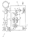
- Fig. 1 is a schematic block diagram of an interferometric optical sensor having amplitude switching in a closed loop serrodyne drive configuration in accordance with a first aspect of the invention.
- Fig. 2 is a diagram illustrating the phase shift imposed on two counter-propagating waves, the phase difference between the two, how this phase difference appears on an optical intensity curve, and the associated time history of the optical intensity.
- Fig. 3 is a graph of a family of curves representing the serrodyne output drive frequency as a function of both serrodyne output drive amplitude and rotation rate.
- Fig. 4 is a schematic block diagram of an interferometric optical sensor having multiple simultaneous serrodyne waveforms applied and controlled in accordance with a second aspect of the invention.
- a closed loop interferometric optical sensor more specifically a fiber optic gyroscope (FOG) 10
- a light source 12 e.g., a laser diode or superluminescent diode.
- Light from the source 12 is optically coupled by known means, e.g., through an optical fiber 14 to a port 16 of an optical assembly 18.
- the optical assembly 18 contains known optical components such as beam splitters (e.g., four port fused-fiber star coupler or integrated optical Y-coupler), polarizers, and single-mode elements (e.g., single-mode fibers or waveguides).
- the components are arranged such that light which has entered at port 16 is first passed through a single-mode single-polarization filter, e.g., a known metallized optical waveguide segment, then split by known means, e.g., a Y-shaped integrated optical (IO) waveguide, into two waves of approximately equal intensities which then exit from the assembly 18 through two ports 20, 22.
- a single-mode single-polarization filter e.g., a known metallized optical waveguide segment
- known means e.g., a Y-shaped integrated optical (IO) waveguide
- the port 22 is optically coupled by known means, e.g., through an optical fiber 24 to a port 26, of a phase modulator assembly 28, which may alternatively be part of the optical assembly 18.
- An optical wave entering port 26 is directed through optical fibers or waveguides, to an optical phase modulator 30.
- the modulator 30 may include, an optical waveguide sandwiched between a pair of parallel electrodes by known techniques.
- the modulator 30 is driven by a modulation signal on a line 32 from a modulation control circuit 34. After passing through the modulator 30, the wave exits the modulator assembly 28 through a port 36.
- the port 36 of the modulator assembly 28 and the port 20 of the optical assembly are optically coupled through optical fibers 38, 40 respectively to opposite ends of an optical fiber 44 wound into a Sagnac sensing loop.
- the fiber 44 typically consists of a single-mode fiber, but may be a multi-mode fiber if desired.
- the loop may consist of a plurality of turns of optical fiber which may be wound on a cylindrical spool (not shown). The two waves, one exiting the port 20 of the optical assembly and the other exiting the port 36 of the phase modulator assembly counter-propagate in the loop.
- the wave that exited the port 20 enters the modulator assembly at the port 36, passes through the modulator 30 and re-enters the optical assembly at the port 22.
- the other wave after traversing the loop, re-enters the optical assembly at the port 20.
- the waves are recombined by known means, e.g., the aforementioned Y-shaped IO waveguides.
- a portion of the recombined light is split off by known means, e.g., a fused-fiber coupler, after again passing through the aforementioned single-mode single-polarization filter to ensure, as is known, reciprocal optical paths for the counter-propagating waves in the FOG in the absence of rotation.
- the split-off portion of the recombined light exits the optical assembly through a port 48 and is optically coupled by known means, e.g., an optical fiber 50, to an optical detector 52, e.g., a photodiode or photodetector.
- the remainder of the recombined light typically exits the optical assembly 18 through the port 16, and may pass through or be absorbed in the light source 12.
- the optical detector 52 provides on a line 54, to the modulation control circuit 34, an electrical signal proportional to the intensity of the optical signal at the port 48 of the optical assembly 18. This optical signal represents the recombined waveform intensity.
- the modulation control circuit 34 monitors the optical intensity on the line 54 and drives the optical phase modulator with a modulation signal on the line 32.
- the closed loop FOG modulation signal may be a stepped ramp or a linear ramp serrodyne signal having a fixed amplitude (or peak) and an essentially instantaneous flyback time.
- the terms 2 ⁇ and ⁇ radians amplitude refer to the amplitude required to induce a peak phase shift of 2 ⁇ and ⁇ radians, respectively on a given wave.
- a 2 ⁇ radians amplitude is used in a fixed amplitude FOG.
- the phase modulator induces a phase difference between counter-propagating waves because it acts on the recombining waves at different times.
- the modulation control circuit of the invention includes a known frequency control circuit 56, that provides an analog serrodyne waveform drive signal on a line 58 responsive to the optical intensity signal on the line 54.
- the frequency control circuit modulates the frequency from a nonrotation setpoint frequency (or control Fe) to null any induced differential phase shift and maintain a constant intensity averaged over the period of the serrodyne drive signal.
- the frequency control circuit contains known electronic components such as a lock-in amplifier (synchronous demodulator), providing an analog voltage proportional to the magnitude of frequency components in the intensity signal, driving a low pass filter, providing a voltage indicative of the time averaged intensity of the frequency components, which drives a voltage controlled oscillator (VCO) to provide a frequency proportional to the time averaged intensity.
- VCO voltage controlled oscillator
- the serrodyne drive signal is provided from the frequency control circuit on the line 58 to a known 2 ⁇ amplitude control circuit 62 where it is scaled to a fixed amplitude of approximately 2 ⁇ radians using known electronic components, e.g., an amplifier.
- the frequency control circuit 56 provides a signal on a line 64 to cause a switch 68 to connect the 2 ⁇ amplitude control circuit 62 to a line 70 which feeds one input of a summer 72 and causes a switch 74 to disconnect the signal path to the other input line 78 of the summer 72 thereby providing a modulation drive signal on the line 32 solely driven by the signal on the line 70.
- the serrodyne drive signal frequency on the line 70 will be related to rotation rate. More specifically, the difference between the drive frequency and the nonrotation setpoint frequency (the control Fe) will be proportional to rotation rate.
- a signal indicative thereof is provided by the frequency control circuit 56 on a line 76 which is the FOG 10 output.
- the serrodyne waveform drive signal on the line 58 is also provided to a ⁇ amplitude control circuit 80 containing known electronic components such as a frequency to voltage converter which controls the gain of a variable gain amplifier.
- the ⁇ amplitude control circuit scales the amplitude of the serrodyne drive signal on the line 58 to approximately ⁇ radians, detects frequency variations in the serrodyne drive signal, and adjusts the amplitude to minimize such variations thereby achieving precisely a ⁇ radians amplitude.
- FOG calibration is selected by the output of a timer located within the frequency control circuit 56.
- the timer initiates calibration by causing the frequency control circuit 56 to provide a signal on the line 64 to cause the switch 68 to connect the ⁇ amplitude control circuit 80 to the line 70 which feeds the summer 72 and causes the switch 74 to connect an undulation source 82 to the other input line 78 of the summer 72 thereby providing a modulation drive signal on the line 32 which is the summation of the signals on the two lines 70, 78.
- the undulation signal from the source 82 provides on the line 78 a predetermined artificial rotation (phase) variation signal such as a low frequency dither, e.g., 1HZ, as a component to the phase modulation drive signal.
- a predetermined artificial rotation (phase) variation signal such as a low frequency dither, e.g., 1HZ, as a component to the phase modulation drive signal.
- the dither manifests itself as a variation in drive signal frequency on the output line 58 of the frequency control circuit 56.
- the ⁇ amplitude control circuit will adjust the amplitude in a direction to minimize the variation in drive frequency. When the frequency variation is extremely small or nonexistent (provided the loop Fe does not change), the amplitude of the signal is precisely ⁇ radians.
- the frequency control circuit modulates the drive frequency to achieve the nonrotation setpoint and the ⁇ amplitude control circuit adjusts the drive amplitude to achieve precisely ⁇ radians amplitude.
- the drive frequency will be independent of rotation rate thereby allowing determination of the loop Fe by monitoring the drive frequency.
- the frequency control circuit After waiting a length of time sufficient to achieve the ⁇ radians amplitude, such as three periods of the undulation frequency (three seconds, for an undulation frequency of 1HZ), the frequency control circuit reads the drive frequency signal on the line 70 (which will now be equal to the loop Fe) and updates the value of the control Fe (which will update the rotation rate). Updating the rotation rate calculation may also be performed without modifying the control Fe.
- the frequency control circuit disengages the FOG calibration by providing a signal on the line 64 to cause the switch 74 to disconnect the undulation source 82, and cause the switch 68 to connect the 2 ⁇ amplitude control circuit to the summer 72 and disconnect the ⁇ radians amplitude control circuit. The system has thereby returned to the 2 ⁇ amplitude closed loop configuration and is capable of measuring rotation rate.
- the waveforms 100, 102 illustrate the ⁇ radians amplitude serrodyne waveform and the associated phase shift ⁇ introduced on the counterclockwise (CCW) and clockwise (CW) traveling waves, respectively.
- the time T represents the time it takes for the wave to traverse the loop.
- the phase shift introduced between the two waves ( ⁇ ) can be determined by subtracting the two waveforms as shown by the curve 104.
- This curve 104 shows the differential phase shift introduced between the two waves to be + ⁇ /2 and - ⁇ /2 with equal times at each level.
- the effect of the differential phase shift ⁇ (curve 104) upon the intensity I of the optical output signal is shown by the raised cosine curve 106.
- the intensity will oscillate from the point 110 to the point 112 in a periodic fashion spending equal times at each intensity.
- the time average output intensity in this case is equal to a constant, corresponding to a ⁇ of ⁇ /2, shown by the curve 114. If the ring is then subject to an arbitrary rotation rate, the operating point on the intensity curve will shift to a related point, such as 116. Again, applying the differential phase shift 104 to the cosine intensity curve 106, the intensity will oscillate by ⁇ /2 from the operating point 116 to two new points 118, 120, again with equal times spent at each intensity.
- the curve 122 shows the time history of the intensity oscillation at the operating point 116.
- the time average intensity 114 is equal to the same constant value as in the previous case, independent of rotation rate. Therefore, the time average intensity seen at the optical detector will be the same constant value, independent of rotation rate, when the serrodyne waveform amplitude is set to precisely ⁇ radians and the frequency is set to Fe. It should be noted that the time delay induced by rotation is many orders of magnitude smaller than the time T to traverse the loop, therefore no appreciable change in the time symmetry of the ⁇ waveform 104 will occur due to rotation.
- Fig. 3 This principle is further illustrated by Fig. 3.
- the x-axis 130 and y-axis 132 represent the amplitude and the frequency of the serrodyne output drive signal respectively.
- the y-axis of Fig. 3 gives the closed loop serrodyne drive output frequency required to null any induced phase shift and obtain a constant optical intensity averaged over the period of the serrodyne drive signal (i.e., the frequency of the signal on the output line 58 of the frequency control circuit).
- the family of curves 134 illustrates the relationship for CCW rotation, curves 136 for CW rotation, and curve 138 for no rotation.
- the change in frequency required to satisfy the closed loop serrodyne drive system is proportional to rotation rate, as indicated by the family of curves 134, 136, 138.
- the frequency at which this occurs is one unique frequency, Fe, as shown by the intersection of all the curves at the point 140.
- Fig. 1 Although the invention is illustrated in Fig. 1 as being implemented with a switched waveform, the invention will work equally as well using two independent serrodyne modulation waveforms with amplitudes ⁇ and 2 ⁇ simultaneously applied to the phase modulator and controlled such that one frequency gives the loop Fe, and the other contains rotation information, as illustrated in Fig. 4.
- the value of the loop Fe is available continuously on the line 70 and rotation information on a line 86.
- the use of simultaneous waveforms in this alternative embodiment eliminates the switch 68 that selects between the ⁇ and 2 ⁇ amplitudes, and the switch 74 that connects the undulation signal.
- the 2 ⁇ amplitude signal on a line 86, the ⁇ amplitude signal on the line 70, and the undulation signal on a line 90 are fed to a summer 88 that replaces the summer 72 of Fig. 1, thereby continuously providing a drive signal on the line 32 comprising three combined waveforms.
- the frequency control circuit for the ⁇ and 2 ⁇ radians amplitudes should be based at different frequencies (such as ⁇ radians amplitude at Fe and 2 ⁇ radians amplitude at 2Fe). Accordingly, the frequency control circuit in this embodiment produces two serrodyne waveform signals based at two different frequencies. An output line 59 provides a path for the additional signal.
- the use of simultaneous waveforms in this alternative embodiment eliminates the overhead associated with switching from the 2 ⁇ radians amplitude control circuit to the ⁇ radians amplitude control circuit and undulation source, thereby eliminating the interruption in rotation rate detection during the time when the ⁇ radians amplitude is applied.
- the invention is illustrated primarily as applied to a rotation sensor, it will work equally as well in applications where optical phase differences between counter-propagating waves in the loop are induced by alternative perturbations, e.g., magnetic fields configured so as to yield a differential phase shift, rather than rotation.
- the controlled modulation signal is illustrated as being a serrodyne ramp signal, other waveforms exhibiting similar phase shifting properties (symmetry) may be used, e.g. a parabolic periodic ramp or any non-linear periodic ramp with a flyback time that is short compared to the forward ramp time, and with an appropriate amplitude.
- the invention is illustrated as comprising in part an optical assembly which may provide optical splitting, filtering, and combining operations, along with a separate modulator assembly, the invention will work equally as well when implemented with the individual components combined in one or more IO devices, in a manner which should be apparent to one skilled in the art in light of the teachings herein.
- the invention may employ an open loop amplitude control without both the undulation source and ⁇ amplitude control logic, provided the ⁇ radians amplitude is precisely known.
- the undulation source is not required.
- the invention may also be implemented with a plurality of phase modulators driven by separate signals, one for each signal component (or a combination thereof) previously described as summed or switched into the modulator drive signal.
- the linearity of the optical system allows the individual effects of each drive signal to be optically combined, thereby forming the total modulation signal.
Claims (7)
- Optisches Interferometer, aufweisend:eine optische Wellenleiter-Schleife (44);Einrichtungen (12,18) zur Vorgabe eines Paares von gegenläufigen Lichtwellen in der Schleife;eine Einrichtung (18) zur Kombination der Lichtwellen nach gegenläufigem Durchlauf der Schleife;eine auf die kombinierten Lichtwellen ansprechende Detektoreinrichtung (52) zur Vorgabe eines elektrischen Detektionssignales (54), das eine Komponente besitzt, welche eine optische Phasendifferenz zwischen den kombinierten Lichtwellen anzeigt, die von einer nicht-reziproken Rotation herrührt, die an die Schleife angelegt wird;eine in der Schleife angeordnete Modulationseinrichtung (30), die auf ein Ansteuersignal (32) anspricht, um eine Phasendifferenz zwischen den gegenläufigen Lichtwellen vorzugeben; undeine Signalverarbeitungseinrichtung (34), die auf das Detektionssignal anspricht, um das Ansteuersignal an die Modulationseinrichtung (30) mit einer Amplitude vorzugeben, um eine Phasenverschiebung von π zu induzieren, die das zeitliche Mittel der Komponente des Detektionssignales an eine konstante Größe unabhängig von der nicht-reziproken Rotation angleicht, wodurch das zeitliche Mittel der konstanten Größe dieser Komponente auf einem Wert gehalten wird, der bei Abwesenheit der nicht-reziproken Rotation vorliegen würde, dadurch gekennzeichnet, daß die Signalverarbeitungseinrichtung (34) umfaßt: Summiereinrichtungen (72, 88) zur Vorgabe des Ansteuersignales (32) als eine Mehrzahl von Signalformen, wobei die Signalformen geliefert werden durch: einen Frequenz-Steuerschaltkreis (56) über einen ersten Amplituden-Steuerschaltkreis (80); undeinen zweiten Amplituden-Steuerschaltkreis (62); und ferner durch eine Schwingungsquelle (82), die ein vorbestimmtes künstliches Rotations-Veränderungssignal vorgibt;wobei der erste Amplituden-Steuerschaltkreis (80) und die Schwingungsquelle (82) zusammenwirken, um ein Korrektursignal (70, 56, 58) an den zweiten Amplituden-Steuerschaltkreis (62) abzugeben.
- Interferometer nach Anspruch 1, dadurch gekennzeichnet, daß der erste Amplituden-Steuerschaltkreis (80) dazu dient, ein π Amplituden-Modulationssignal abzugeben und daß der zweite Amplituden-Steuerschaltkreis (62) dazu dient, ein 2 π Amplituden-Modulationssignal abzugeben.
- Interferometer nach Anspruch 2, gekennzeichnet durch Schalteinrichtungen (68, 74) zum Aufschalten der Signale des ersten Amplituden-Steuerschaltkreises (80) und der Schwingungsquelle (82) gemeinsam auf die Summiereinrichtung (72).
- Interferometer nach Anspruch 2, dadurch gekennzeichnet, daß die ersten und zweiten Amplituden-Steuerschaltkreise (80, 62) und die Schwingungsquelle (82) gleichzeitig an die Summiereinrichtung (88) angeschlossen sind.
- Interferometer nach einem der Ansprüche 1 bis 4, gekennzeichnet durch mehrere Modulatoreinrichtungen, jeweils für eine getrennte Signalform, die das Ansteuersignal (32) ausmachen und die an einem Ende oder beiden Enden der optischen Wellenleiter-Schleife (44) angeordnet sind.
- Interferometer nach Anspruch 1, dadurch gekennzeichnet, daß die optische Wellenleiter-Schleife eine optische Faser (44) umfaßt.
- Interferometer nach einem der Ansprüche 1 bis 6, dadurch gekennzeichnet, daß das optische Interferometer als ein faseroptischer Kreisel (10) konfiguriert ist.
Applications Claiming Priority (2)
| Application Number | Priority Date | Filing Date | Title |
|---|---|---|---|
| US07/658,808 US5170225A (en) | 1991-02-22 | 1991-02-22 | Determining optical signal transit delay time in an optical interferometer |
| PCT/US1992/002746 WO1993020408A1 (en) | 1991-02-22 | 1992-04-07 | Determining optical signal transit delay time in an optical interferometer |
Publications (2)
| Publication Number | Publication Date |
|---|---|
| EP0635117A1 EP0635117A1 (de) | 1995-01-25 |
| EP0635117B1 true EP0635117B1 (de) | 1996-09-04 |
Family
ID=24642788
Family Applications (1)
| Application Number | Title | Priority Date | Filing Date |
|---|---|---|---|
| EP92914756A Expired - Lifetime EP0635117B1 (de) | 1991-02-22 | 1992-04-07 | Bestimmung der laufzeit des optischen signals in einem optischen interferometer |
Country Status (7)
| Country | Link |
|---|---|
| US (1) | US5170225A (de) |
| EP (1) | EP0635117B1 (de) |
| JP (1) | JP2838592B2 (de) |
| KR (1) | KR950701066A (de) |
| CA (1) | CA2122906C (de) |
| DE (1) | DE69213477T2 (de) |
| WO (1) | WO1993020408A1 (de) |
Families Citing this family (8)
| Publication number | Priority date | Publication date | Assignee | Title |
|---|---|---|---|---|
| US6246816B1 (en) * | 1999-07-30 | 2001-06-12 | Litton Systems, Inc. | Wavelength stabilized laser light source |
| US7176447B2 (en) * | 2005-03-08 | 2007-02-13 | Agilent Technologies, Inc. | Electro-optic delay line frequency discriminator |
| US7515272B2 (en) * | 2006-03-17 | 2009-04-07 | Honeywell International Inc. | Digital feedback systems and methods for optical gyroscopes |
| US7872758B2 (en) * | 2007-01-22 | 2011-01-18 | The Charles Stark Draper Laboratory, Inc. | Determining and compensating for modulator dynamics in interferometric fiber-optic gyroscopes |
| US7817284B2 (en) * | 2007-08-08 | 2010-10-19 | The Charles Stark Draper Laboratory, Inc. | Interferometric fiber optic gyroscope with off-frequency modulation signals |
| US8717575B2 (en) | 2011-08-17 | 2014-05-06 | Honeywell International Inc. | Systems and methods for environmentally insensitive high-performance fiber-optic gyroscopes |
| RU2482450C1 (ru) * | 2011-12-16 | 2013-05-20 | Федеральное государственное унитарное предприятие "Центр эксплуатации объектов наземной космической инфраструктуры" (ФГУП "ЦЭНКИ") | Устройство тестирования электронного блока волоконно-оптического гироскопа |
| CN115143949B (zh) * | 2022-09-05 | 2022-11-18 | 中国船舶重工集团公司第七0七研究所 | 超高精度光纤陀螺仪本征频率补偿及故障诊断处理方法 |
Family Cites Families (5)
| Publication number | Priority date | Publication date | Assignee | Title |
|---|---|---|---|---|
| DE3104786A1 (de) * | 1981-02-11 | 1982-09-02 | Licentia Patent-Verwaltungs-Gmbh, 6000 Frankfurt | "verfahren und anordnung zur messung absoluter drehungen" |
| GB8611394D0 (en) * | 1986-05-08 | 1986-10-29 | British Aerospace | Fibre optic gyroscopes |
| FR2613067B1 (fr) * | 1987-03-27 | 1989-06-23 | Thomson Csf | Procede et dispositif de detection des variations de temps de propagation dans un interferometre en anneau et leur application au controle de longueur d'onde |
| US5090809A (en) * | 1990-06-04 | 1992-02-25 | Ferrar Carl M | Modulation frequency control in a fiber optic rotation sensor |
| US5137357A (en) * | 1990-06-27 | 1992-08-11 | Honeywell Inc. | Interferometric signal analysis with modulation switching |
-
1991
- 1991-02-22 US US07/658,808 patent/US5170225A/en not_active Expired - Lifetime
-
1992
- 1992-04-07 CA CA002122906A patent/CA2122906C/en not_active Expired - Fee Related
- 1992-04-07 DE DE69213477T patent/DE69213477T2/de not_active Expired - Lifetime
- 1992-04-07 WO PCT/US1992/002746 patent/WO1993020408A1/en active IP Right Grant
- 1992-04-07 EP EP92914756A patent/EP0635117B1/de not_active Expired - Lifetime
- 1992-04-07 JP JP4511635A patent/JP2838592B2/ja not_active Expired - Fee Related
-
1994
- 1994-10-07 KR KR1019940703586A patent/KR950701066A/ko not_active Application Discontinuation
Also Published As
| Publication number | Publication date |
|---|---|
| CA2122906C (en) | 2001-03-27 |
| EP0635117A1 (de) | 1995-01-25 |
| DE69213477T2 (de) | 1997-02-13 |
| WO1993020408A1 (en) | 1993-10-14 |
| DE69213477D1 (de) | 1996-10-10 |
| KR950701066A (ko) | 1995-02-20 |
| JPH07504493A (ja) | 1995-05-18 |
| CA2122906A1 (en) | 1993-10-14 |
| JP2838592B2 (ja) | 1998-12-16 |
| US5170225A (en) | 1992-12-08 |
Similar Documents
| Publication | Publication Date | Title |
|---|---|---|
| EP0532679B1 (de) | Regelung der modulationsfrequenz in einem faseroptischen rotationssensor | |
| US5090810A (en) | Ring resonator gyroscope controlling two servo control loops based on the output of a single interference detector | |
| US4687330A (en) | Fiber optic rotation sensor with extended dynamic range | |
| US5321503A (en) | Closed loop, depolarized interferometric fiber optic (IFOG) gyroscope with self adjusting serrodyne phase nulling | |
| US4661964A (en) | Resonant waveguide laser gyro with a switched source | |
| JPS61222288A (ja) | 角速度センサ | |
| US5398111A (en) | Optically-locked fiber-optic resonant gyro | |
| US4948252A (en) | Sub-tau phase modulation in a fiber-optic rotation sensor | |
| US4573795A (en) | Rotation rate measuring instrument | |
| JP2567486B2 (ja) | 閉ループ光ファイバジャイロスコープ | |
| US5237387A (en) | Dual serrodyne resonator fiber optic gyroscope | |
| JP2724915B2 (ja) | 変調切換えを伴なう干渉計信号解析 | |
| EP0635117B1 (de) | Bestimmung der laufzeit des optischen signals in einem optischen interferometer | |
| EP0416531A2 (de) | Faserkreisel mit Ringresonator und sein Betriebsverfahren | |
| EP0587202A2 (de) | Optischer Faserkreisel | |
| EP0160450B1 (de) | Fasern ablesendes faseroptisches Interferometer | |
| US4702601A (en) | Method and apparatus for measuring rate of rotation by the sagnac effect | |
| JP2909513B2 (ja) | リング共振ジャイロ | |
| EP0153123B1 (de) | Faseroptischer Rotationssensor mit Torschaltung und mit erweitertem dynamischem Messbereich | |
| JPS61147106A (ja) | 位相変調方式光フアイバジヤイロ | |
| US4906096A (en) | Apparatus and method for phase modulating optical signals in a fiber optic rotation sensor | |
| RU2234680C2 (ru) | Способ стабилизации масштабного коэффициента волоконно-оптического гироскопа | |
| JPS622121A (ja) | 光フアイバジヤイロスコ−プ | |
| Bergh et al. | CONTROLLER PC2 POLARIZER | |
| JPS6078314A (ja) | 光フアイバジヤイロ |
Legal Events
| Date | Code | Title | Description |
|---|---|---|---|
| PUAI | Public reference made under article 153(3) epc to a published international application that has entered the european phase |
Free format text: ORIGINAL CODE: 0009012 |
|
| 17P | Request for examination filed |
Effective date: 19941014 |
|
| AK | Designated contracting states |
Kind code of ref document: A1 Designated state(s): DE FR GB IT NL SE |
|
| 17Q | First examination report despatched |
Effective date: 19950628 |
|
| GRAG | Despatch of communication of intention to grant |
Free format text: ORIGINAL CODE: EPIDOS AGRA |
|
| GRAH | Despatch of communication of intention to grant a patent |
Free format text: ORIGINAL CODE: EPIDOS IGRA |
|
| GRAH | Despatch of communication of intention to grant a patent |
Free format text: ORIGINAL CODE: EPIDOS IGRA |
|
| GRAA | (expected) grant |
Free format text: ORIGINAL CODE: 0009210 |
|
| AK | Designated contracting states |
Kind code of ref document: B1 Designated state(s): DE FR GB IT NL SE |
|
| PG25 | Lapsed in a contracting state [announced via postgrant information from national office to epo] |
Ref country code: NL Free format text: LAPSE BECAUSE OF FAILURE TO SUBMIT A TRANSLATION OF THE DESCRIPTION OR TO PAY THE FEE WITHIN THE PRESCRIBED TIME-LIMIT Effective date: 19960904 Ref country code: IT Free format text: LAPSE BECAUSE OF FAILURE TO SUBMIT A TRANSLATION OF THE DESCRIPTION OR TO PAY THE FEE WITHIN THE PRE;WARNING: LAPSES OF ITALIAN PATENTS WITH EFFECTIVE DATE BEFORE 2007 MAY HAVE OCCURRED AT ANY TIME BEFORE 2007. THE CORRECT EFFECTIVE DATE MAY BE DIFFERENT FROM THE ONE RECORDED.SCRIBED TIME-LIMIT Effective date: 19960904 |
|
| ET | Fr: translation filed | ||
| REF | Corresponds to: |
Ref document number: 69213477 Country of ref document: DE Date of ref document: 19961010 |
|
| PG25 | Lapsed in a contracting state [announced via postgrant information from national office to epo] |
Ref country code: SE Effective date: 19961204 |
|
| NLV1 | Nl: lapsed or annulled due to failure to fulfill the requirements of art. 29p and 29m of the patents act | ||
| PLBE | No opposition filed within time limit |
Free format text: ORIGINAL CODE: 0009261 |
|
| STAA | Information on the status of an ep patent application or granted ep patent |
Free format text: STATUS: NO OPPOSITION FILED WITHIN TIME LIMIT |
|
| 26N | No opposition filed | ||
| REG | Reference to a national code |
Ref country code: GB Ref legal event code: IF02 |
|
| PGFP | Annual fee paid to national office [announced via postgrant information from national office to epo] |
Ref country code: GB Payment date: 20050314 Year of fee payment: 14 |
|
| PG25 | Lapsed in a contracting state [announced via postgrant information from national office to epo] |
Ref country code: GB Free format text: LAPSE BECAUSE OF NON-PAYMENT OF DUE FEES Effective date: 20060407 |
|
| GBPC | Gb: european patent ceased through non-payment of renewal fee |
Effective date: 20060407 |
|
| PGFP | Annual fee paid to national office [announced via postgrant information from national office to epo] |
Ref country code: FR Payment date: 20110331 Year of fee payment: 20 |
|
| PGFP | Annual fee paid to national office [announced via postgrant information from national office to epo] |
Ref country code: DE Payment date: 20110429 Year of fee payment: 20 |
|
| REG | Reference to a national code |
Ref country code: DE Ref legal event code: R071 Ref document number: 69213477 Country of ref document: DE |
|
| REG | Reference to a national code |
Ref country code: DE Ref legal event code: R071 Ref document number: 69213477 Country of ref document: DE |
|
| PG25 | Lapsed in a contracting state [announced via postgrant information from national office to epo] |
Ref country code: DE Free format text: LAPSE BECAUSE OF EXPIRATION OF PROTECTION Effective date: 20120408 |
|
| P01 | Opt-out of the competence of the unified patent court (upc) registered |
Effective date: 20230525 |