EP0634682A2 - Interferenzmikroskop durch Lichtdifferenz und Beobachtungsverfahren unter Benutzung desselben - Google Patents
Interferenzmikroskop durch Lichtdifferenz und Beobachtungsverfahren unter Benutzung desselben Download PDFInfo
- Publication number
- EP0634682A2 EP0634682A2 EP94304936A EP94304936A EP0634682A2 EP 0634682 A2 EP0634682 A2 EP 0634682A2 EP 94304936 A EP94304936 A EP 94304936A EP 94304936 A EP94304936 A EP 94304936A EP 0634682 A2 EP0634682 A2 EP 0634682A2
- Authority
- EP
- European Patent Office
- Prior art keywords
- light
- image
- beams
- differential interference
- optical system
- Prior art date
- Legal status (The legal status is an assumption and is not a legal conclusion. Google has not performed a legal analysis and makes no representation as to the accuracy of the status listed.)
- Ceased
Links
Images


Classifications
-
- G—PHYSICS
- G02—OPTICS
- G02B—OPTICAL ELEMENTS, SYSTEMS OR APPARATUS
- G02B21/00—Microscopes
- G02B21/06—Means for illuminating specimens
- G02B21/08—Condensers
- G02B21/14—Condensers affording illumination for phase-contrast observation
-
- G—PHYSICS
- G02—OPTICS
- G02B—OPTICAL ELEMENTS, SYSTEMS OR APPARATUS
- G02B21/00—Microscopes
Definitions
- the present invention relates to a differential interference microscope apparatus employed for observing, e.g., a living specimen.
- the present invention also relates to an observing method using the differential interference microscope apparatus.
- a conventional differential interference microscope includes, e.g., a transmitted illumination type of microscope as shown in FIGS. 5A and 5B.
- This type of differential interference microscope is constructed as follows. Referring to FIG. 5A, a specimen is Koehler-illuminated with a beam of light from a light source S through lenses L1, L2 and a condenser lens L3. The transmitted light of this specimen M forms a magnified image Y via an objective lens L4. The magnified image Y is observed with a naked eye through an eyepiece L in a microscope optical system.
- This microscope optical system incorporates differential interference members, i.e., a polarizer P, an analyzer A, a Wollaston prism W1 and a Wollaston prism W2.
- the Wollaston prism W1 is disposed in a position of entrance pupil of the condenser lens L3.
- the Wollaston prism W2 is disposed in a position of exit pupil of the objective lens L4.
- the polarizer P is disposed on this side (on the side of the light source S) of the Wollaston prism W1.
- the analyzer A is disposed in rear (on the side of the eyepiece L5) of the Wollaston prism W2.
- the Wollaston prism is, as illustrated in FIG. 6, constructed by bonding two pieces of right-angle prisms cut out in a state where directions of their optical axes are orthogonal to each other.
- the directions (shown by arrowheads) of one optical axis are set parallel to the sheet surface, while the directions (marked with (+)) of the other optical axis are set perpendicular to the sheet surface.
- This prism separates a beam of incident light into two beams of rectilinear polarized light having oscillatory planes orthogonal to each other.
- the beam of incident light is separated into the two beams of polarized light at an angle-of-deviation ⁇ determined by an apical angle ⁇ of the right-angle prism.
- the angle-of-deviation ⁇ is given by: ⁇ 2(n e - n0) tan ⁇ , where n e is the refractive index of the Wollaston prism with respect to an extraordinary ray, and n0 is the refractive index of the Wollaston prism with respect to an ordinary ray.
- the rectilinear polarized light in the arrowed direction is taken out of the light emerging from the light source S by means of the polarizer P.
- This rectilinear polarized light is separated by the Wollaston prism W1 at the angle-of-deviation ⁇ into the two beams of rectilinear polarized light, which are orthogonal to each other.
- the Wollaston prism is selected corresponding to an objective lens employed but is replaced together when exchanging the objective lens.
- the thus separated two light beams fall on the condenser lens L3. If the Wollaston prism W1 is located on a front-side focal plane of the condenser lens L3 at this time, however, the two beams of rectilinear polarized light become parallel beams spaced by a quantity (shear quantity) S away from each other.
- the specimen M is then irradiated with the parallel beams.
- the two light beams penetrating the specimen M converge on a rear-side focal plane of the objective lens L4 via the objective lens L4 and become a single beam of light through the Wollaston prism W2 disposed therein. This beam of light travels on the same optical path. With a further transmission through the analyzer A, antiphase components of these two light beams are taken out, resulting an interference with each other.
- the differential interference microscope utilizes this principle. Even when the specimen M is colorless and transparent, but if there is caused the difference in the optical path between the two light beams in accordance with a difference in terms of a thickness or a refractive index within the specimen M, the specimen M can be observed with a difference in brightness.
- the specimen is observed mainly with the naked eye, and therefore, the image Y is required to have a contrast to some extent.
- This contrast is determined by a magnitude of the shear quantity S.
- the shear quantity S may be increased. Supposing that, for instance, as illustrated in FIG. 7A, a portion M' exhibiting a high refractive index exists in the specimen M, and when the same phasic plane of the beam is expressed by a line segment ab, the incident light ab, after passing through the specimen M, travels forward taking a shape a'b'. At this time, the two light beams spaced by the shear quantity S are overlapped with each other as shown in FIG. 7B.
- the contrast is, however, obtained with brightness and darkness, which are produced due to an optical path difference ⁇ between the two light beams.
- the optical path difference ⁇ between the two light beams resulting in a lower contrast.
- the shear quantity S is taken large, the contrast is enhanced.
- the contrast between the brightness and darkness is produced even with a slight inclination.
- the image Y of the specimen M looks double. Further, even when the shear quantity S is not so large but set under the resolving power ⁇ of the objective lens L4, and if set in the vicinity of the resolving power ⁇ , there happens such a phenomenon that the image is extended in the direction of this shear quantity S.
- a differential interference microscope apparatus comprising: a light source; a condenser optical system for condensing beams of light from the light source and illuminating an object with the beams of light; an objective optical system for converging the beams of light from the illuminated object and forming an image of the object; a pick-up device for photoelectrically detecting the image of the object; and a contrast enhancement circuit for enhancing a contrast of the image on the basis of an output signal of the image of the object photoelectrically detected by the pick-up device.
- a first polarizing element and a first birefringent element are disposed sequentially from the side of the light source in an optical path between the light source and the object.
- the first polarizing element changes the beams of light from the light source into predetermined beams of polarized light.
- the first birefringent element separates the polarized light into an ordinary ray and an extraordinary ray.
- a second birefringent element and a second polarizing element are disposed sequentially from the side of the object in an optical path between the object and the image.
- the second birefringent element guides the two light beams from the object onto the same optical path.
- the second polarizing element causes the two light beams guided onto the same optical path to interfere with each other.
- the shear quantity S between the ordinary ray and the extraordinary ray satisfies the following condition: ⁇ / 20 ⁇ S ⁇ ⁇ / 2 where ⁇ is the resolving power of the objective optical system.
- a method of observing an object by use of a differential interference microscope apparatus comprising: a first step of converting a beam of light from a light source into a predetermined beam of polarized light; a second step of separating the predetermined beam of polarized light into two light beams of an ordinary ray and an extraordinary ray; a third step of irradiating the object with the two light beams; a fourth step of guiding the two light beams via the object onto the same optical path; a fifth step of causing the two light beams guided onto the same optical path to interfere with each other; a sixth step of forming an image of the object on the basis of the two light beams interfered with each other by converging action of the objective optical system; a seventh step of photoelectrically converting the formed image; and an eighth step of enhancing a contrast of the image on the basis of an output of the photoelectrically converted image.
- the light beam from the light source is changed by the first polarizing element into the predetermined beam of polarized light.
- the birefringent element such as the Wollaston prism separates the polarized light into two light beams of the ordinary ray and the extraordinary ray.
- the two light beams are condensed by the condenser lens, and the object is illuminated with the condensed light.
- the two light beams through the object are guided by the second birefringent element onto the same optical path.
- the second polarizing element causes the light beams to interfere with each other.
- the differential interference microscope thus obtains a differential interference image.
- the pick-up element photoelectrically detects the image of the object with respect to the above differential interference image.
- the contrast enhancement circuit enhances the contrast if the image of the object detected by the pick-up element.
- the present invention it is feasible to catch the image through the objective lens as an extremely sharp differential interference image and, at the same time, eventually obtain the observation image with a high contrast. This is done without a decline of the image quality while making use of the resolving power of the objective lens as in the case where the image of the object looks double, or the hyperfine portions appear with no contrast.
- the shear quantity S is set to satisfy the above-mentioned conditional expression (1) where ⁇ is the resolving power of the objective lens according to the present invention. If under a lower limit of this conditional expression, the shear quantity S is too small, resulting in an extremely small interference effect of the two light beams. Even when enhancing the contrast, a high contrast enough for the observation can not be obtained. Further, it is difficult to manufacture the crystal optical element (Wollaston prism) acting to remarkably reduce the shear quantity S, i.e., decrease the angle-of-separation ⁇ between the ordinary ray and the extraordinary ray.
- the crystal optical element Wollaston prism
- the resolving power is spoiled as in the same way with the conventional differential interference microscope.
- This is disadvantageous in terms of observing the object in the vicinity of a limit of the resolving power.
- the observation image exhibiting the high contrast can be obtained while making use of the resolving power of the objective lens all the time by limiting the shear quantity S within a range of the conditional expression (1).
- the shear quantity range shown in the conditional expression (1) is further set such as: ⁇ / 20 ⁇ S ⁇ 2 ⁇ / 5.
- the present invention may take a construction in which the condenser optical system and the objective optical system are used in common.
- the first and second birefringent elements are employed in common.
- an optical path splitter is disposed in the optical path between the first polarizing element and the first birefringent element.
- the object is irradiated with the two light beams separated by the first birefringent element through the condenser lens.
- the light beams reflected from the object travel on a retro-directive course and are again condensed through the condenser lens.
- the light beams are further guided by the first birefringent element onto the same optical path. Thereafter, the light beams are guided by the optical path splitting element to the second polarizing element, thereby making the two light beams interfere with each other.
- a differential interference image of the object can be thus obtained.
- This image is, in the same way as the mode of this invention, photoelectrically detected by the pick-up element in the observing element.
- the contrast of the image is enhanced by the contrast enhancing element.
- FIG. 1A illustrates a transmitted illumination type of differential interference microscope apparatus by way of a first embodiment of the present invention.
- a specimen 7 is illuminated with the light emerging from a light source 1 through a lens 2, a lens 3 and a condenser lens 6, thereby obtaining a magnified image 11 through an objective lens 8.
- the thus constructed microscope incorporates, as differential interference members, a polarizer 4, an analyzer 10, a Wollaston prism 5 and a Wollaston prism 9.
- the Wollaston prism 5 is disposed in a position of entrance pupil of the condenser lens 6.
- the Wollaston prism 9 is disposed in a position of exit pupil of the objective lens 8.
- the polarizer 4 is placed on this side (on the side of the light source 1) of the Wollaston prism 5.
- the analyzer 10 is placed in rear of the Wollaston prism 9.
- the rectilinear polarized light is taken out of the light emerging from the light source 1 by means of the polarizer 4.
- This rectilinear polarized light is separated by the Wollaston prism 5 at an angle-of-deviation ⁇ into two beams of rectilinear polarized light, which are orthogonal to each other.
- the thus separated two light beams are incident on a condenser lens 6 and become parallel beams spaced by a shear quantity S away from each other.
- a specimen 7 is irradiated with these parallel beams of light.
- the two light beams penetrating the specimen 7 converge on a rear-side focal plane of the objective lens 8 via the objective lens 8 and become a single beam of light through the Wollaston prism 9 disposed therein. This beam of light travels on the same optical path.
- antiphase components of these two light beams are taken out, resulting an interference with each other.
- a differential interference image is thereby formed on an image surface 11.
- the Wollaston prisms 5 and 9 are structured so that the shear quantity S in the specimen 7 with respect to the resolving power ⁇ of the objective lens 8 is set within a range defined by ⁇ / 20 ⁇ S ⁇ ⁇ / 2.
- the differential interference image on the image surface 11 is extremely sharp in terms of image because of the shear quantity S being extremely smaller than in the prior arts.
- the differential interference image is, however, low of contrast and can not be therefore captured with a naked eye and an ordinary video camera or the like.
- this embodiment involves the use of a contrast enhancement circuit 13 for performing a video-enhancement for enhancing this contrast.
- the contrast enhancement circuit 13 is provided between a monitor 14 and a pick-up device 12 such as an image pick-up tube and a CCD for photoelectrically detecting the image on the image surface 11.
- FIG. 1B shows an example of the contrast enhancement in this embodiment.
- an intensity of the contrast is expressed, wherein the axis of abscissa indicates the position x, and the axis of ordinate one-dimensionally represents the intensity I.
- an input signal Si from the pick-up device 12 is simply amplified and outputted in the form of a signal So onto the monitor 14. Even when a contrast of the input signal Si is weak under a threshold value with which a naked-eye observable state is attained in the conventional differential interference microscope, the output So exhibits a well-observed contrast on the monitor 14.
- a method of enhancing the contrast involves detecting, as illustrated in, e.g., FIG. 1C, an edge portion of the input signal Si transmitted from the pickup device 12 by taking a differential of the input signal Si once or twice. It is thus possible to increase or decrease intensities of the signals corresponding to a wave-crest and a wave-trough of the edge portion and further to employ a so-called edge enhancement technique.
- a signal S1 on the monitor 14 undergoes a simple amplification of the input signal Si as shown in FIG. 1B in combination with the edge enhancement.
- the method of enhancing the contrast may include a step of changing a relationship of the intensity of the output signal with respect to the intensity of the input signal by use of a non-linear function.
- the shear quantity S is set to ⁇ /5 and ⁇ /10 ( ⁇ : the resolving power of the objective lens 8), and the specimen is observed. Consequently, a sharp observation image is obtained, and there can be seen an image exhibiting a more impact with a high contrast than seeing it with the naked eye through the conventional differential interference microscope in both cases.
- this embodiment may take such a construction that the output signals from the contrast enhancement circuit 13 are recorded on a video recording device, a magneto-optic recording device or a memory.
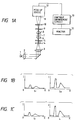
- FIG. 2 illustrates a reflection (vertical illumination) type of differential interference microscope by way of a second embodiment of this invention.
- a beam of light from a light source 21 is collimated into parallel beams of light through a collector lens 22. Thereafter, an image thereof is formed by a lens 24 on the pupil plane of an objective lens 27.
- a specimen surface 28 is illuminated with the light through the objective lens 27.
- a beam of light reflected from the specimen surface 28 passes again through the objective lens 27, thereby obtaining an image 30.
- the thus constructed reflection type microscope incorporates a polarizer 23, an analyzer 29 and a Wollaston prism 26.
- the Wollaston prism 26 is disposed on the pupil plane of the objective lens 27.
- the Wollaston prism 26 is constructed so that the shear quantity is, as in the same way with the first embodiment, set to satisfy the above conditional expression (1).
- the rectilinear polarized light is taken out of the light emerging from the light source 21 by means of the polarizer 23.
- This rectilinear polarized light is separated into two beams of rectilinear polarized light which are orthogonal to each other by the Wollaston prism 26 via the lens 24 and a half-mirror 25.
- the image on the image surface 30 is, as in the same way with the first embodiment, photoelectrically detected by a pick-up element such as a CCD and an image pick-up tube.
- a contrast thereof is enhanced by a contrast enhancement circuit 32 and thereafter displayed on a screen of the monitor 33. This displayed image exhibits a sharpness and a high contrast.
- the embodiment discussed above takes the construction in which the objective lens is of a finite system, and the second birefringent element and the second polarizing element are disposed between the objective lens and the image surface.
- the present invention is not, however, confined to this construction.
- the construction may be such that the objective lens 8 is of the finite system as in the first embodiment, the second birefringent element 9 is located between the specimen 7 and the objective lens 8, and a second polarizing element 10 is disposed between the objective lens 8 and the image surface 11.
- the first birefringent element 5 is disposed between the condenser lens 6 and the specimen 7.
- the first polarizing element 4 is located on the side of the light source (between the lens 3 and the condenser lens 6) of the condenser lens 6.
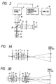
- the objective lens 8 shown in FIG. 3A is structured in the form of a two-lens system consisting of lenses 81, 82, and a parallel system (infinity system) is provided between the respective lenses.
- the second birefringent element 9 and the second polarizing element 10 may be disposed sequentially from the side of the specimen 7 in the parallel beams of light thereof.
- the condenser lens 6 is structured, as in the same way with the objective lens 8, in the form of the two-lens system consisting of lenses 61, 62, and the parallel system (infinity system) is provided between the respective lenses.
- the first birefringent element 5 and the first polarizing element 4 are disposed sequentially from the side of the specimen 7 in the parallel beams of light thereof.
- FIGS. 3A and 3B illustrate examples of the transmitted illumination type differential interference microscope.
- the reflective illumination type differential interference microscope as shown in FIG. 2 may also be employed by such an arrangement that the condenser lens 6 and the objective lens 8 are used in common, the birefringent elements 5, 9 are used in common, and the polarizing elements 4, 10 are also used in common.
- the Wollaston prisms are employed as the birefringent elements.
- the present invention is not, however, limited to this case but may be applicable to any arrangement wherein the rectilinear polarized light taken out by the first polarizing element can be separated into the two beams of rectilinear polarized light orthogonal to each other at a predetermined angle of deviation.
- the focal position may exist in the objective lens constructed of a plurality of lens elements.
- a Nomarski prism (a modified Wollaston prism) shown in FIG. 4 is usable.
- This Nomarski prism intends to separate the light into two light beams in a position spaced by a distance d away from the prism.
- a point-of-separation H is set in a position of pupil of the objective lens, there can be obtained the same action as setting the Wollaston prism in the position of pupil.
Landscapes
- Physics & Mathematics (AREA)
- Chemical & Material Sciences (AREA)
- Analytical Chemistry (AREA)
- General Physics & Mathematics (AREA)
- Optics & Photonics (AREA)
- Microscoopes, Condenser (AREA)
- Polarising Elements (AREA)
- Lenses (AREA)
Applications Claiming Priority (2)
| Application Number | Priority Date | Filing Date | Title |
|---|---|---|---|
| JP19671793A JP3656252B2 (ja) | 1993-07-15 | 1993-07-15 | 微分干渉顕微鏡 |
| JP196717/93 | 1993-07-15 |
Publications (2)
| Publication Number | Publication Date |
|---|---|
| EP0634682A2 true EP0634682A2 (de) | 1995-01-18 |
| EP0634682A3 EP0634682A3 (de) | 1996-01-03 |
Family
ID=16362429
Family Applications (1)
| Application Number | Title | Priority Date | Filing Date |
|---|---|---|---|
| EP94304936A Ceased EP0634682A3 (de) | 1993-07-15 | 1994-07-05 | Interferenzmikroskop durch Lichtdifferenz und Beobachtungsverfahren unter Benutzung desselben. |
Country Status (3)
| Country | Link |
|---|---|
| US (1) | US5572359A (de) |
| EP (1) | EP0634682A3 (de) |
| JP (1) | JP3656252B2 (de) |
Cited By (3)
| Publication number | Priority date | Publication date | Assignee | Title |
|---|---|---|---|---|
| DE19626261A1 (de) * | 1995-06-30 | 1997-01-02 | Nikon Corp | Beobachtungsvorrichtung |
| DE10219804A1 (de) * | 2002-04-30 | 2003-11-13 | Zeiss Carl Jena Gmbh | Anordnung und Verfahren zum polarisationsoptischen Interferenzkontrast |
| EP2241920A4 (de) * | 2008-01-23 | 2014-04-23 | Nikon Corp | Mikroskopsystem |
Families Citing this family (24)
| Publication number | Priority date | Publication date | Assignee | Title |
|---|---|---|---|---|
| US5751475A (en) * | 1993-12-17 | 1998-05-12 | Olympus Optical Co., Ltd. | Phase contrast microscope |
| US7218448B1 (en) | 1997-03-17 | 2007-05-15 | The Regents Of The University Of Colorado | Extended depth of field optical systems |
| US6911638B2 (en) | 1995-02-03 | 2005-06-28 | The Regents Of The University Of Colorado, A Body Corporate | Wavefront coding zoom lens imaging systems |
| US20020195548A1 (en) * | 2001-06-06 | 2002-12-26 | Dowski Edward Raymond | Wavefront coding interference contrast imaging systems |
| US20020118457A1 (en) * | 2000-12-22 | 2002-08-29 | Dowski Edward Raymond | Wavefront coded imaging systems |
| US5969855A (en) * | 1995-10-13 | 1999-10-19 | Olympus Optical Co., Ltd. | Microscope apparatus |
| US6038067A (en) * | 1996-05-23 | 2000-03-14 | The Regents Of The University Of California | Scanning computed confocal imager |
| US6005709A (en) * | 1996-06-05 | 1999-12-21 | Marine Biological Laboratory | Microscope system for using transmitted light to observe living organisms |
| JPH10133123A (ja) * | 1996-09-04 | 1998-05-22 | Nikon Corp | 透過照明型微分干渉顕微鏡 |
| JP3708260B2 (ja) * | 1996-12-05 | 2005-10-19 | オリンパス株式会社 | 微分干渉顕微鏡 |
| JPH11212028A (ja) * | 1998-01-26 | 1999-08-06 | Nikon Corp | コントラスト改善機能を有する光学装置およびコントラスト改善方法 |
| SG95602A1 (en) * | 1999-08-07 | 2003-04-23 | Inst Of Microelectronics | Apparatus and method for image enhancement |
| DE50111807D1 (de) * | 2000-06-14 | 2007-02-15 | Deutsch Zentr Luft & Raumfahrt | Verfahren zur quantitativen optischen messung der topographie einer oberfläche |
| US6536898B1 (en) * | 2000-09-15 | 2003-03-25 | The Regents Of The University Of Colorado | Extended depth of field optics for human vision |
| US6873733B2 (en) | 2001-01-19 | 2005-03-29 | The Regents Of The University Of Colorado | Combined wavefront coding and amplitude contrast imaging systems |
| US20060023225A1 (en) * | 2001-06-14 | 2006-02-02 | Carl Zeiss | Microscope and method of measurement of a surface topography |
| US6842297B2 (en) | 2001-08-31 | 2005-01-11 | Cdm Optics, Inc. | Wavefront coding optics |
| DE10247248A1 (de) * | 2002-10-10 | 2004-04-22 | Leica Microsystems Wetzlar Gmbh | Polarisations-Interferenzmikroskop |
| TW201015109A (en) * | 2008-10-03 | 2010-04-16 | Ind Tech Res Inst | Differential interference contrast microscope |
| CN102297722B (zh) * | 2011-09-05 | 2014-08-06 | 西安交通大学 | 一种双通道差分偏振干涉成像光谱仪 |
| CN105959514B (zh) * | 2016-04-20 | 2018-09-21 | 河海大学 | 一种弱目标成像检测装置 |
| WO2019006433A1 (en) * | 2017-06-30 | 2019-01-03 | Preza Chrysanthe | MULTILAYER LIGHT SHEET STRUCTURED LIGHT EMITTING FLUORESCENCE MICROSCOPY SYSTEM |
| CN114778552A (zh) * | 2022-04-14 | 2022-07-22 | 中电科风华信息装备股份有限公司 | 一种用二次分束实现指向无依赖的差分干涉相衬成像系统 |
| CN115166062B (zh) * | 2022-08-22 | 2024-06-11 | 天津大学 | 一种基于差分干涉的全光学超声探测器及探测方法 |
Family Cites Families (6)
| Publication number | Priority date | Publication date | Assignee | Title |
|---|---|---|---|---|
| US3561876A (en) * | 1968-03-11 | 1971-02-09 | Robert Hoffman | Detecting and measuring apparatus using polarization interferometry |
| US4412246A (en) * | 1981-07-13 | 1983-10-25 | Hamamatsu Systems, Inc. | Method of adjusting a video microscope system incorporating polarization or interference optics for optimum imaging conditions |
| US4752567A (en) * | 1984-06-21 | 1988-06-21 | Janssen Pharmaceutica N.V. | Method of visualizing individual submicroscopic metal particles |
| US4795246A (en) * | 1987-07-30 | 1989-01-03 | Loro Albert | Differential interference contrast microscope using non-uniformly deformed plastic birefringent components |
| JPH02151825A (ja) * | 1988-12-05 | 1990-06-11 | Olympus Optical Co Ltd | 微分干渉顕微鏡 |
| GB2235788A (en) * | 1989-09-06 | 1991-03-13 | Asahi Optical Co Ltd | Image stabilizing apparatus |
-
1993
- 1993-07-15 JP JP19671793A patent/JP3656252B2/ja not_active Expired - Lifetime
-
1994
- 1994-06-30 US US08/269,125 patent/US5572359A/en not_active Expired - Lifetime
- 1994-07-05 EP EP94304936A patent/EP0634682A3/de not_active Ceased
Cited By (6)
| Publication number | Priority date | Publication date | Assignee | Title |
|---|---|---|---|---|
| DE19626261A1 (de) * | 1995-06-30 | 1997-01-02 | Nikon Corp | Beobachtungsvorrichtung |
| US5764363A (en) * | 1995-06-30 | 1998-06-09 | Nikon Corporation | Apparatus for observing a surface using polarized light |
| DE10219804A1 (de) * | 2002-04-30 | 2003-11-13 | Zeiss Carl Jena Gmbh | Anordnung und Verfahren zum polarisationsoptischen Interferenzkontrast |
| EP1359453A3 (de) * | 2002-04-30 | 2004-08-11 | CARL ZEISS JENA GmbH | Anordnung und Verfahren zum polarisationsoptischen Interferenzkontrast |
| US7046436B2 (en) | 2002-04-30 | 2006-05-16 | Carl Zeiss Jena Gmbh | Arrangement and method for polarization-optical interference contrast |
| EP2241920A4 (de) * | 2008-01-23 | 2014-04-23 | Nikon Corp | Mikroskopsystem |
Also Published As
| Publication number | Publication date |
|---|---|
| US5572359A (en) | 1996-11-05 |
| EP0634682A3 (de) | 1996-01-03 |
| JPH0735982A (ja) | 1995-02-07 |
| JP3656252B2 (ja) | 2005-06-08 |
Similar Documents
| Publication | Publication Date | Title |
|---|---|---|
| EP0634682A2 (de) | Interferenzmikroskop durch Lichtdifferenz und Beobachtungsverfahren unter Benutzung desselben | |
| US5355252A (en) | Scanning laser microscope | |
| EP0592089B1 (de) | Konfokales Rastermikroskop mit kontinuierlicher Anzeige | |
| JPH11135U (ja) | 共焦点レ―ザ―走査顕微鏡 | |
| EP0353495B1 (de) | Anordnung zur Erzeugung eines optischen Bildkontrastes | |
| US4720191A (en) | Method and apparatus for light span microscopic dark-field display of objects | |
| DE19626261A1 (de) | Beobachtungsvorrichtung | |
| CN110709749B (zh) | 组合式明视场和相衬显微镜系统及配备其的图像处理设备 | |
| US6690520B1 (en) | Optical system for visualizing an object in a light scattering medium | |
| Wilson et al. | Difference confocal scanning microscopy | |
| CH689703A5 (de) | Photomikroskop. | |
| EP1906224B1 (de) | Konfokale Mikroskopvorrichtung | |
| Inoué | Progress in video microscopy | |
| Awamura et al. | Color laser microscope | |
| JP3237023B2 (ja) | 位置検出装置 | |
| JPS60181718A (ja) | 同期走査顕微鏡 | |
| JP3144513B2 (ja) | 蛍光顕微鏡 | |
| JP2004177732A (ja) | 光学測定装置 | |
| JPH09281401A (ja) | 物体検査装置 | |
| JPH09281402A (ja) | 物体観察装置 | |
| DE102010001467A1 (de) | Sondenmikroskop | |
| JP3061758B2 (ja) | 顕微鏡用の自動合焦装置 | |
| Warnke et al. | AN APPLICATION OF REFLECTED‐LIGHT DIFFERENTIAL‐INTERFERENCE MICROSCOPY: BEACH STUDIES IN EASTERN LONG ISLAND (USA) | |
| JP2795142B2 (ja) | 暗視装置 | |
| JPH03131811A (ja) | 共焦点走査型透過顕微鏡 |
Legal Events
| Date | Code | Title | Description |
|---|---|---|---|
| PUAI | Public reference made under article 153(3) epc to a published international application that has entered the european phase |
Free format text: ORIGINAL CODE: 0009012 |
|
| AK | Designated contracting states |
Kind code of ref document: A2 Designated state(s): DE FR GB |
|
| PUAL | Search report despatched |
Free format text: ORIGINAL CODE: 0009013 |
|
| AK | Designated contracting states |
Kind code of ref document: A3 Designated state(s): DE FR GB |
|
| 17P | Request for examination filed |
Effective date: 19960329 |
|
| 17Q | First examination report despatched |
Effective date: 19981230 |
|
| GRAG | Despatch of communication of intention to grant |
Free format text: ORIGINAL CODE: EPIDOS AGRA |
|
| STAA | Information on the status of an ep patent application or granted ep patent |
Free format text: STATUS: THE APPLICATION HAS BEEN REFUSED |
|
| 18R | Application refused |
Effective date: 20000129 |