EP0634648A1 - Device for the optoelectric surface inspection - Google Patents
Device for the optoelectric surface inspection Download PDFInfo
- Publication number
- EP0634648A1 EP0634648A1 EP94104585A EP94104585A EP0634648A1 EP 0634648 A1 EP0634648 A1 EP 0634648A1 EP 94104585 A EP94104585 A EP 94104585A EP 94104585 A EP94104585 A EP 94104585A EP 0634648 A1 EP0634648 A1 EP 0634648A1
- Authority
- EP
- European Patent Office
- Prior art keywords
- light
- chamber
- sensor
- housing
- opening
- Prior art date
- Legal status (The legal status is an assumption and is not a legal conclusion. Google has not performed a legal analysis and makes no representation as to the accuracy of the status listed.)
- Withdrawn
Links
Images
Classifications
-
- G—PHYSICS
- G01—MEASURING; TESTING
- G01N—INVESTIGATING OR ANALYSING MATERIALS BY DETERMINING THEIR CHEMICAL OR PHYSICAL PROPERTIES
- G01N21/00—Investigating or analysing materials by the use of optical means, i.e. using sub-millimetre waves, infrared, visible or ultraviolet light
- G01N21/84—Systems specially adapted for particular applications
- G01N21/88—Investigating the presence of flaws or contamination
- G01N21/8806—Specially adapted optical and illumination features
-
- G—PHYSICS
- G01—MEASURING; TESTING
- G01N—INVESTIGATING OR ANALYSING MATERIALS BY DETERMINING THEIR CHEMICAL OR PHYSICAL PROPERTIES
- G01N21/00—Investigating or analysing materials by the use of optical means, i.e. using sub-millimetre waves, infrared, visible or ultraviolet light
- G01N21/84—Systems specially adapted for particular applications
- G01N2021/845—Objects on a conveyor
-
- G—PHYSICS
- G01—MEASURING; TESTING
- G01N—INVESTIGATING OR ANALYSING MATERIALS BY DETERMINING THEIR CHEMICAL OR PHYSICAL PROPERTIES
- G01N21/00—Investigating or analysing materials by the use of optical means, i.e. using sub-millimetre waves, infrared, visible or ultraviolet light
- G01N21/84—Systems specially adapted for particular applications
- G01N21/86—Investigating moving sheets
- G01N2021/8609—Optical head specially adapted
- G01N2021/8627—Optical head specially adapted with an illuminator over the whole width
-
- G—PHYSICS
- G01—MEASURING; TESTING
- G01N—INVESTIGATING OR ANALYSING MATERIALS BY DETERMINING THEIR CHEMICAL OR PHYSICAL PROPERTIES
- G01N21/00—Investigating or analysing materials by the use of optical means, i.e. using sub-millimetre waves, infrared, visible or ultraviolet light
- G01N21/84—Systems specially adapted for particular applications
- G01N21/88—Investigating the presence of flaws or contamination
- G01N21/8851—Scan or image signal processing specially adapted therefor, e.g. for scan signal adjustment, for detecting different kinds of defects, for compensating for structures, markings, edges
- G01N2021/8887—Scan or image signal processing specially adapted therefor, e.g. for scan signal adjustment, for detecting different kinds of defects, for compensating for structures, markings, edges based on image processing techniques
-
- G—PHYSICS
- G01—MEASURING; TESTING
- G01N—INVESTIGATING OR ANALYSING MATERIALS BY DETERMINING THEIR CHEMICAL OR PHYSICAL PROPERTIES
- G01N2201/00—Features of devices classified in G01N21/00
- G01N2201/10—Scanning
- G01N2201/102—Video camera
Definitions
- Such a unit is described in its own earlier utility model G 92 02 306.
- light sources for diffuse but essentially directed, large-area irradiation of an object are arranged at the edge of a curved reflector, the contours of which are recorded in the radiation direction of the reflector by means of a camera serving as an optronic sensor behind an opening in the center of the reflector.
- This lighting ensures that all partial contours are illuminated equally, that is to say that no lighting-related falsification due to shadow-related reinforcements or overlaps occurs during the recording.
- the invention is based on the object of creating a compact detection unit for optronic surface inspection, which can be integrated retrospectively into the production process, in particular for the classification of rapidly moving workpieces, with which even low-contrast surface imperfections can be reliably detected by different sensor characteristics .
- a stable, compact and therefore logistically unproblematic housing is designed with parallel sensor and light chambers that are easily accessible for the exchange of equipment via the wide side walls and that face towards the workpiece surface to be inspected and moved relative to it with an opposite view opening Complete the inclined light opening.
- the characteristics of the lighting and the sensor aperture in the direction of the workpiece feed are narrow and wide across (i.e. not in the form of a beam, but linear or stripe-shaped), and they therefore intersect along a line on the workpiece surface of interest. The entire lighting intensity is concentrated on this recording line across the workpiece movement.
- the direction of irradiation is inclined so that with a single structure, both high-contrast structures and low-contrast imperfections (such as depressions or holes, but also surface roughness) can be reliably detected, which lead to only small local shadows.
- the housing with ready-to-use equipment adjusted with regard to the light source and sensor also contains a power supply unit for its operation and an interface for evaluating the information recorded by the sensor.
- This compact detection unit which is comparatively narrow in the scanning and transport direction, can, if necessary, be installed at any point in the production process, namely opposite the workpiece surface to be inspected at a distance which is caused by the cutting of the and directions of irradiation is determined, for example below a roller conveyor for the longitudinal transport of planed profile boards or cast plastic and metal parts.
- the detection unit can be equipped with different sensors, so instead of with line or point or area cameras, with color sensors or with active sensors (for laser or radar scanning) and with additional sensors such as light barriers to determine the start and end of a workpiece, with speedometers for sample length evaluation or with monitoring sensors for lighting failure or critical heating of the workpiece surface.
- the light source can be equipped with high-frequency-fed fluorescent tubes in a semi-hollow cylindrical reflector in order to irradiate a streak-free illuminated strip concentrically to a line detected by the sensor on the workpiece surface in the case of oblique light incidence without great heat generation.
- such cold-light noble gas tubes do not in themselves result in a high light density, and the axially parallel arrangement in the semi-cylindrical hollow reflector does not produce a clearly focused, narrow lighting strip on the surface to be inspected for reasons of geometric optics.
- the use of DC-powered halogen spotlights with integrated focusing is more appropriate.
- Two or more spotlights are grouped according to the sensor recording characteristic.
- a line sensor For a line sensor, several concentrated low-voltage lamps are arranged side by side parallel to its orientation.
- a single high-voltage, high-performance halogen tube can also be installed in this orientation, as used in floodlights for site lighting.
- a direct current supply is recommended. This is inexpensively available by rectifying a three-phase AC voltage, since the phase shift produces only a small residual ripple, which then no longer interferes due to the thermal inertia of the tube.
- the tube In order to be able to vary the setting of the focus line, the tube can expediently be adjusted relative to the longitudinal axis (namely transversely against it).
- a significant increase by focusing the light area on the recording region on the inspection surface can still be achieved by replacing or supplementing the glass plate at the end of the light chamber with a lens adapted to the scanning geometry.
- a half cylinder lens Because of the increased light density in the narrow detection strip across the movement of the workpiece scanned by a line scan camera, it allows a reduction in the electrical power of the built-in halogen spotlight and thus a significant reduction in heat loss in the hermetically sealed housing.
- This advantage can also be achieved by a transmissive or reflective focusing built into the light chamber in front of the halogen light source; in the case of transmissive focusing with a lens, the heat loss can be realized more cheaply with an external arrangement on or instead of the glass plate, if the effects of beam deflection and focusing within the light chamber are not to be summarized constructively.
- the radiation geometry on the workpiece surface which is desirable with regard to the sensor geometry, can finally also be realized by cross-sectional transformation using light guides.
- the workpieces 11, the flat surfaces 12 of which are to be optically inspected, for example, for classification purposes or generally for quality control purposes, can be castings made of plastic or metal stretched in the transport direction 13, which have surface defects in the form of cavities and poorly separated sprues can.
- it is preferably planed boards and beams, which are to be classified according to defects 14 in particular in the form of continuous (knot) holes, larger depressions and resin or knot stains that contrast in color with the surroundings.
- imperfections 14 with strong brightness contrast with respect to their surroundings are detected comparatively reliably by an optronic sensor 15, preferably a line scan camera, when the surface 12 is scanned in relative movement between workpiece 11 and sensor 15, mere depressions 14.1 without color contrast to the surroundings are much more difficult to detect to capture.
- This applies correspondingly to holes 14.2 which, in relation to their diameter or to the height of the workpiece 11, are inclined so much with respect to the surface 12 that, for geometric reasons, the contrasting perspective situation in the recording direction does not result.
- the direction of irradiation 17 is inclined by approximately 45 ° (measured against the transport direction 13) with respect to the surface 12 to be inspected and accordingly also by approximately 45 ° with respect to the recording direction 16 oriented transversely to the surface 12. This always results on the edge of depressions 14.1 and of holes 14.2 with respect to the direction of irradiation 17 and thus in the direction of transport 13 a small shadow cast and thus an easily detectable defect contrast even without a view through conditions.
- the light source 18 for the direction of irradiation 17 is located in the two-part housing 19 of an optoelectronic scanning or detection unit 20, in which a not quite as long sensor chamber 21.4 is formed parallel to a light chamber 21.3.
- the chambers 21 are stretched in the receiving direction 16.
- the sensor 15 is arranged opposite the viewing opening 22.5 in the remote area of the sensor chamber 21.4 in order to achieve the largest possible object distance, so that when using a telephoto intermediate ring on the optics 23 of a line sensor 15 the surface 12 across the entire width of the workpiece to the transport direction 13 can be detected.
- the large distance also results in optimal imaging conditions with regard to depth of field and largely independence from the intensity of the illumination retroreflection on the inspected surface 12, which fluctuates per se according to the cosine law.
- the adjacent area of the light chamber 21.3 is closed off with a light opening 22.6.
- Both openings 22 are closed in a dust-tight manner by glass plates 24 which are framed on the housing 19 and are plane-parallel. They are oriented at an obtuse angle to one another orthogonally to the directions of exposure or irradiation 16, 17 in order to avoid scattering and reflections on the glass plates 24 in the object image or when the light passes through, which could otherwise interfere with the surface patterns to be evaluated.
- the sensor 15 is connected via an interface 25 to an evaluation circuit of the type described in the publication "Real time surface grading of profiled wooden boards" by W. Pölzleitner and G. Schwingshakl in INDUSTRIAL METROLOGY Vol. 2, Nos. 3-4, 1992, pp. 283-298, in particular for the classification of planed profiled boards is described in detail.
- Such an evaluation circuit can supply control information 26 to a sorter 27, which, as sketched, can simply be an adjustable stop 28 in front of a cross conveyor 29 for removal of the inspected workpieces 11 or a fully automatic sorting switch.
- the comparatively heavy power supply unit 30 for the operational supply of the sensor 15 together with the interface 25 and in particular for the power supply of the light source 18 is preferably arranged opposite the light opening 22.6 in the lower region of the light chamber 21.3 when the detection unit 20 is designed as a floor-standing device for reasons of stability.
- the power supply unit 30 is, in particular, a frequency converter if the light source 18 is in a trough-shaped, hollow cylindrical reflector 31 with parallel to the reflector axis (and thus corresponding to the narrow strip recorded on the surface 12 by a line scan camera transversely to the plane of illustration 1) extending cold light fluorescent tubes 32 is equipped. To avoid optical beating, they are operated at a high frequency in the order of a few tens of kHz.
- noble gas fluorescent tubes 32 are characterized by a long service life and low heat loss, but do not provide the ideal radiation spectrum and the ideal radiation geometry for some surface inspection requirements (especially when considering the grain pattern in planed wood).
- halogen lamps 33 are preferably not arranged directly in parallel behind the glass plate 24 of the light opening 22.6, but rather is offset considerably along the resulting beam path.
- the halogen emitters 33 are oriented approximately parallel to the light opening 22.6 on the radiation side, with their radiation being deflected at a mirror 34 for perpendicular passage of the irradiation direction 17 through the light opening glass plate 24. This creates a very large air space between the halogen lamps 33 and the glass plate 24 in front of the light opening 22.6 and thus the desirable large heat capacity for the halogen lamp heat loss.
- a fan 35 can counteract heat accumulation behind the glass plate 24 by forced circulation.
- explosion protection safety requirements for example in the woodworking industry, prohibit air exchange with the surroundings outside the hermetically sealed housing 19. Therefore the blower 35 is arranged in the partition 39 between the light chamber 21.3 and the sensor chamber 21.4, as far as possible in the housing 19, ie as close as possible behind the panes 24 and thus close to the heat and light source 18.
- the direction of flow of the circulating air 40 is preferably such that the warm air from the surroundings of the light source 18 is not blown directly onto the camera (sensor 15 with optics 23), but rather that at the sensor 15 only the direction of the convection through the light chamber 21.3 downward circulating air 40 passes after having already experienced a certain cooling in this way.
- part of its outer wall 42 is designed as a heat exchanger 43 with a massive plate 44 and ribs 45 projecting approximately at right angles therefrom and running parallel to the longitudinal extent of the light chamber 21.3, or such a heat exchanger 43 is formed inserted into a recess in the outer wall 42.
- the circulating air flow 40 which is pushed down by the fan 35 in the light chamber 21.3, passes through the ribs 45 for heat emission in the longitudinal direction before it passes through the openings 41 into the sensor chamber 21.4 and is pushed up or sucked up again there as a cooled air flow 40.
- the heat exchanger plate 44 is preferably also equipped with ribs 45 outside the housing 19.
- a ventilation box 46 with a fan 47 can be placed thereon, which causes a forced flow through the outer ribs 45 for increased heat dissipation.
- an air-water heat exchanger can also be provided, which then no longer requires an external fan 47; or as a heat exchanger 43, an air conditioner is used in the outer wall 42, the evaporator of which lies in the circulating air flow 40 through the light chamber 21.3, while the compressor and condenser of the air conditioner are arranged outside the housing 19. If within the light opening 22.6 a number of externally pressurized air jets 48 protrude into the light chamber 21.3, by means of which at least the light disk 24 (but possibly also the sensor disk 24) is blown free of deposits resulting from the circulating air flow 40 air turbulence and thus heat dissipation is additionally promoted.
- a significant increase in efficiency as a result of better, for example, linear focusing of the light radiation on the surface 12 can also be achieved by additionally focusing the halogen lamp radiation by means of a semi-cylindrical lens 38 in this example.
- a light source 18 of lower electrical power and thus also less heat loss can then be used for the same illumination.
- the lens 38 itself can be arranged within the light chamber 21.3 in the beam path between the light source 18 and the glass plate 24 or even combined with the mirror 34, but would reduce the air volume desirable there for reasons of heat capacity. Therefore, it can also be considered, as taken into account in FIG. 2, to arrange the lens 38 on the glass plate 24 in front of the light chamber 21.3 or to replace this glass plate directly with the lens 38.
- the compact, fully functional detection unit 20 can easily be integrated into a production system, for example at the exit of a planing machine 36 under the roller conveyor 37 for the removal of workpieces 11 in shape of profiled boards, the planed underside of which is to be inspected for quality classification.
- the completely closed housing meets 19 requirements for use in potentially explosive environments. Since the recording and viewing directions 16, 17 are already adjusted when the sensor 15 and the light source 18 are installed, the integration of this self-aligned detection unit 20 into the manufacturing process means that no further complex adjustment processes are required.
Landscapes
- Physics & Mathematics (AREA)
- Health & Medical Sciences (AREA)
- Life Sciences & Earth Sciences (AREA)
- Chemical & Material Sciences (AREA)
- Analytical Chemistry (AREA)
- Biochemistry (AREA)
- General Health & Medical Sciences (AREA)
- General Physics & Mathematics (AREA)
- Immunology (AREA)
- Pathology (AREA)
- Investigating Materials By The Use Of Optical Means Adapted For Particular Applications (AREA)
Abstract
Eine Erfassungseinheit (20) als Scan-Box für die optronische Inspektion einer Oberfläche (12) längs einer Folge nebeneinander versetzter paralleler Streifen, insbesondere zur Klassifikation schnell bewegter Werkstücke (11) wie gehobelter Profilbretter, weist ein Gehäuse (19) mit einer Lichtkammer (21.3) und einer parallel dazu sich erstreckenden Sensorkammer (21.4) zur Aufnahme eines Sensors (15) etwa in Form einer Zeilenkamera mit langer Brennweite auf. Die von der Aufnahmerichtung (16) orthogonal durchsetzte Blicköffnung (22.5) und die von der Bestrahlungsrichtung (17) orthogonal durchsetzte Lichtöffnung (22.6) im Gehäuse (19) sind mittels Glasplatten (24) verschlossen, die zwischeneinander einen stumpfen Winkel einschließen, so daß die streifenförmigen Strahlen sich in einem Fokus an der Oberfläche (12) schneiden, die dadurch bei orthogonaler Aufnahmerichtung (16) eine schräge Bestrahlungsrichtung (17) erfährt, um kontrastarme Oberflächen-Fehler wie Vertiefungen, Erhöhungen und Öffnungen von nicht direkt durchblickbaren Löchern durch kleine Schattenränder zuverlässiger zu erfassen. Die Lichtquelle (18) kann mit hochfrequenzgespeisten Leuchtstoffröhren (32) vor einem gestreckt-wannenförmigen Hohlreflektor (31) bestückt sein; zweckmäßiger jedoch mit wenigstens einem punktförmigen (oder mit einem gestreckten) gleichspannungs-betriebenen Halogenstrahler mit Reflektor. Vorzugsweise erfolgt eine Strahlumlenkung in der Lichtkammer (21.3), um einen großen Abstand zwischen Strahler (33) und Glasplatte (24) zu erzielen und die Verlustwärme mittels eines Gebläses (35) für eine Zwangs-Umluft (40) durch die Kammern (21) innerhalb des explosionssicher gekapselten Gehäuses (19) abführen zu können.
Description
Eine solche Einheit ist im eigenen älteren Gebrauchsmuster G 92 02 306 beschrieben. Dort sind am Rande eines gewölbten Reflektors Lichtquellen zu diffuser aber im wesentlichen gerichteter, großflächiger Bestrahlung eines Objektes angeordnet, dessen Konturen in Abstrahlrichtung des Reflektors mittels einer als optronischem Sensor dienenden Kamera hinter einer Öffnung im Zentrum des Reflektors aufgenommen werden. Diese Beleuchtung stellt sicher, daß alle Teilkonturen gleich ausgeleuchtet werden, also bei der Aufnahme keine beleuchtungsbedingte Verfälschung durch schattenbedingte Verstärkungen oder Überdeckungen auftritt.Such a unit is described in its own earlier utility model G 92 02 306. There, light sources for diffuse but essentially directed, large-area irradiation of an object are arranged at the edge of a curved reflector, the contours of which are recorded in the radiation direction of the reflector by means of a camera serving as an optronic sensor behind an opening in the center of the reflector. This lighting ensures that all partial contours are illuminated equally, that is to say that no lighting-related falsification due to shadow-related reinforcements or overlaps occurs during the recording.
Für eine rasche Oberflächen-Inspektion durch dicht gestaffeltes z. B. zeilenförmiges Abtasten quer zur relativen Bewegungsrichtung zwischen Werkstück und Sensor ist eine solche Bestrahlung aber wenig sinnvoll, weil dann nur ein von einer Zeilenkamera gerade aufgenommener zeilenförmiger Bereich inmitten der breit ausgestrahlten Fläche Informationen erbringt. Auch ist eine zur Aufnahmerichtung koaxiale Bestrahlungsrichtung zwar zweckmäßig für die Erfassung gegeneinander kontrastierender Konturen und für die Detektion von in Aufnahmerichtung das Werkstück durchsetzenden Löchern. Dagegen stellen sich Detektionsprobleme ein, wenn es sich statt eines durchgehenden Loches nur um eine Vertiefung handelt, bzw. wenn das Loch das Werkstück so stark geneigt gegenüber der Aufnahmerichtung durchquert, daß sich kein freies Blickfeld durch das Loch hindurch ergibt. Fehlerstrukturen dieser Art, aber auch Informationen über die Oberflächenrauhigkeit, sind deshalb mit der vorstehend erwähnten konzentrischen Anordnung von Lichtquelle und Sensor schwer bis gar nicht zu erfassen.For a quick surface inspection through densely staggered z. B. line-shaped scanning transverse to the relative direction of movement between the workpiece and the sensor, such irradiation is not very useful, because then only a line-shaped area just recorded by a line camera in the middle of the broadly emitted area provides information. An irradiation direction coaxial with the recording direction is also expedient for the detection of contours contrasting against one another and for the detection of holes penetrating the workpiece in the recording direction. In contrast, there are detection problems a, if it is only a recess instead of a through hole, or if the hole crosses the workpiece so strongly inclined with respect to the recording direction that there is no free field of view through the hole. Defect structures of this type, but also information about the surface roughness, are therefore difficult or impossible to detect with the aforementioned concentric arrangement of the light source and sensor.
Aus dem Buch Computer Control Systems For Log Processing And Lumber Manufacturing (Miller Freeman Publications, San Francisco, 1985) von Ed M. Williston, dort Erläuterung zu Fig. 12-1 auf den Seiten 229/230, ist es bekannt, zur meßtechnischen Erfassung des Waldkanten-Verlaufes von Brettern diese von einander gegenüberliegenden Richtungen aus jeweils so schräg anzustrahlen, daß sich längs der Kante ein deutlicher Schattenwurf als kontrastreiche Begrenzungslinie für die optronische Breitenvermessung einstellt. Dabei erfolgt die Bestrahlung zweckmäßigerweise gleich über eine größere Distanz in Richtung der Brett-Länge. Die Bretter-Oberfläche erfährt Beleuchtungen unter Überlagerung der beiden entgegengesetzt geneigten Bestrahlungs-Richtungen, so daß sich dort insgesamt wieder die oben schon erörterte diffuse Beleuchtung mit einer resultierenden Komponente einstellt, die im wesentlichen koaxial zur Aufnahmerichtung des optronischen Sensors quer zur Werkstück-Oberfläche orientiert ist.From the book Computer Control Systems For Log Processing And Lumber Manufacturing (Miller Freeman Publications, San Francisco, 1985) by Ed M. Williston, there explanation to Fig. 12-1 on pages 229/230, it is known for metrological detection the course of the forest edges of boards to illuminate them so diagonally from opposite directions that a clear shadow appears along the edge as a high-contrast boundary line for the optronic width measurement. The irradiation is expediently carried out over a greater distance in the direction of the board length. The board surface is illuminated by superimposing the two oppositely inclined directions of irradiation, so that overall the diffuse illumination discussed above with a resulting component is again obtained, which is oriented essentially coaxially to the recording direction of the optronic sensor across the workpiece surface .
Der Erfindung dagegen liegt die Aufgabe zugrunde, eine kompakte, leicht nachträglich in den produktionsablauf integrierbare Erfassungseinheit für die optronische Oberflächeninspektion, insbesondere zur Klassifikation schnell bewegter Werkstücke, zu schaffen, mit der auch an sich kontrastarme Oberflächen-Fehlstellen von unterschiedlichen Sensor-Charakteristiken zuverlässig erfaßbar sind.The invention, on the other hand, is based on the object of creating a compact detection unit for optronic surface inspection, which can be integrated retrospectively into the production process, in particular for the classification of rapidly moving workpieces, with which even low-contrast surface imperfections can be reliably detected by different sensor characteristics .
Diese Aufgabe ist erfindungsgemäß im wesentlichen dadurch gelöst, daß die gattungsgemäße Erfassungseinheit nach dem Anspruch 1 ausgelegt ist.This object is essentially achieved in that the generic detection unit is designed according to claim 1.
Nach dieser Lösung ist ein stabiles, kompaktes und dadurch logistisch unproblematisches Gehäuse mit zueinander parallelen, zum Bestückungsaustausch über die breiten Seitenwände gut zugänglichen Sensor- und Lichtkammern ausgestaltet, die in Richtung auf die zu inspizierende und relativ dazu bewegte Werkstück-Oberfläche mit einer gegenüber der Blicköffnung geneigten Lichtöffnung abschließen. Das erbringt eine gegenüber der Aufnahmerichtung geneigte Bestrahlungsrichtung. Bei Einsatz eines Zeilensensors sind die Charakteristiken der Beleuchtung und der Sensorapertur in Richtung des Werkstückvorschubs schmal und quer dazu breit (also nicht strahl- sondern linien- oder streifenförmig), und sie schneiden sich somit längs einer Linie auf der interessierenden Werkstück-Oberfläche. Die gesamte Beleuchtungsintensität ist auf diese Aufnahmezeile quer zur Werkstückbewegung konzentriert. Gegenüber der orthogonalen Blickrichtung gegen die Werkstück-Oberfläche ist die Bestrahlungsrichtung so geneigt, daß mit einem einzigen Aufbau sowohl kontrastreiche Strukturen wie auch kontrastarme Fehlstellen (wie Vertiefungen oder Lochansätze, aber auch Oberflächenrauhigkeiten) zuverlässig erfaßbar sind, die zu nur kleinen lokalen Schattenwürfen führen.According to this solution, a stable, compact and therefore logistically unproblematic housing is designed with parallel sensor and light chambers that are easily accessible for the exchange of equipment via the wide side walls and that face towards the workpiece surface to be inspected and moved relative to it with an opposite view opening Complete the inclined light opening. This results in an irradiation direction that is inclined with respect to the recording direction. When using a line sensor, the characteristics of the lighting and the sensor aperture in the direction of the workpiece feed are narrow and wide across (i.e. not in the form of a beam, but linear or stripe-shaped), and they therefore intersect along a line on the workpiece surface of interest. The entire lighting intensity is concentrated on this recording line across the workpiece movement. Compared to the orthogonal viewing direction towards the workpiece surface, the direction of irradiation is inclined so that with a single structure, both high-contrast structures and low-contrast imperfections (such as depressions or holes, but also surface roughness) can be reliably detected, which lead to only small local shadows.
Das Gehäuse mit hinsichtlich Lichtquelle und Sensor einsatzfertig justierter Ausstattung enthält außerdem ein Netzteil zu deren Betrieb und eine Schnittstelle für die Auswertung der vom Sensor aufgenommenen Informationen. Diese kompakte, dabei in Abtast- und Transportrichtung vergleichsweise schmale Erfassungseinheit kann bedarfsweise an beliebiger Stelle des Fabrikationsablaufes installiert werden, nämlich der zu inspizierenden Werkstück-Oberfläche gegenüber in einem Abstand, der durch den Schnitt von Aufnahme- und Bestrahlungsrichtungen bestimmt ist, etwa unterhalb einer Rollenbahn zum in Längsrichtung erfolgenden Abtransport gehobelter Profilbretter oder gegossener Kunststoff- und Metallteile. Die Erfassungeinheit kann bedarfsweise mit unterschiedlichen Sensoren ausgestattet werden, so statt mit Linien- auch mit Punkt- oder Flächenkameras, mit Farbsensoren oder mit aktiven Sensoren (zur Laser- oder Radarabtastung) und mit Zusatzsensoren wie Lichtschranken zum Feststellen des Anfangs und des Endes eines Werkstückes, mit Geschwindigkeitsmessern für die Musterlängenauswertung oder mit Überwachungssensoren für Ausfall der Beleuchtung oder kritische Erwärmung der Werkstück-Oberfläche.The housing with ready-to-use equipment adjusted with regard to the light source and sensor also contains a power supply unit for its operation and an interface for evaluating the information recorded by the sensor. This compact detection unit, which is comparatively narrow in the scanning and transport direction, can, if necessary, be installed at any point in the production process, namely opposite the workpiece surface to be inspected at a distance which is caused by the cutting of the and directions of irradiation is determined, for example below a roller conveyor for the longitudinal transport of planed profile boards or cast plastic and metal parts. If necessary, the detection unit can be equipped with different sensors, so instead of with line or point or area cameras, with color sensors or with active sensors (for laser or radar scanning) and with additional sensors such as light barriers to determine the start and end of a workpiece, with speedometers for sample length evaluation or with monitoring sensors for lighting failure or critical heating of the workpiece surface.
Die Lichtquelle kann für die Zeileninspektion mit hochfrequenz-gespeisten Leuchtstoffröhren in einem halb-hohlzylindrischen Reflektor bestückt sein, um ohne große Wärmeentwicklung einen schwebungsfrei ausgeleuchteten Streifen konzentrisch zu einer vom Sensor an der Werkstück-Oberfläche erfaßten Zeile bei schrägem Lichteinfall zu bestrahlen. Allerdings ergeben solche Kaltlicht-Edelgasröhren schon an sich keine hohe Lichtdichte, und die achsparalle Anordnung im halbzylindrischen Hohlreflektor erbringt aus Gründen der geometrischen Optik auch keinen eindeutig fokussierten, schmalen Beleuchtungsstreifen auf der zu inspizierenden Oberfläche.For the line inspection, the light source can be equipped with high-frequency-fed fluorescent tubes in a semi-hollow cylindrical reflector in order to irradiate a streak-free illuminated strip concentrically to a line detected by the sensor on the workpiece surface in the case of oblique light incidence without great heat generation. However, such cold-light noble gas tubes do not in themselves result in a high light density, and the axially parallel arrangement in the semi-cylindrical hollow reflector does not produce a clearly focused, narrow lighting strip on the surface to be inspected for reasons of geometric optics.
Wegen ihrer hohen und konstanten Lichtenergie ist der Einsatz von gleichstromgespeisten Halogen-Strahlern mit integrierter Fokussierung zweckmäßiger. Zwei oder mehr Punktstrahler werden entsprechend der Sensor-Aufnahmecharakteristik gruppiert. Für einen Zeilensensor sind mehrere konzentrierte Niedervoltlampen parallel zu dessen Orientierung nebeneinander angeordnet. Es kann aber auch eine einzige hochspannungsgespeiste Hochleistungs-Halogenröhre in dieser Orientierung eingebaut sein, wie sie in Flutlichtstrahlern zur Baustellen-Ausleuchtung Einsatz findet. Zur Vermeidung von die Bildaufnahme störenden Schwebungen ist allerdings eine Gleichstromspeisung empfehlenswert. Die ist durch Gleichrichtung einer dreiphasigen Wechselspannung preisgünstig verfügbar, da der Phasenversatz eine nur geringe Restwelligkeit erbringt, die aufgrund der thermischen Trägheit der Röhre dann nicht mehr stört. Um die Einstellung der Fokuslinie variieren zu können, ist die Röhre zweckmäßigerweise relativ zur Längsachse (nämlich quer dagegen) einstellbar.Because of their high and constant light energy, the use of DC-powered halogen spotlights with integrated focusing is more appropriate. Two or more spotlights are grouped according to the sensor recording characteristic. For a line sensor, several concentrated low-voltage lamps are arranged side by side parallel to its orientation. However, a single high-voltage, high-performance halogen tube can also be installed in this orientation, as used in floodlights for site lighting. In order to avoid beats that interfere with image recording, a direct current supply is recommended. This is inexpensively available by rectifying a three-phase AC voltage, since the phase shift produces only a small residual ripple, which then no longer interferes due to the thermal inertia of the tube. In order to be able to vary the setting of the focus line, the tube can expediently be adjusted relative to the longitudinal axis (namely transversely against it).
Wegen der außerordentlich hohen Hitzeentwicklung von punktförmigen oder linienförmigen Halogenlampen werden diese zweckmäßigerweise nicht direkt hinter der die Lichtkammer an ihrer Lichtöffnung abschließenden Glasplatte, sondern in größerem Abstand dazu angeordnet, um durch größeres Luftvolumen zwischen Halogenlampe und Glasplatte eine größere Wärmekapazität und verbesserte Möglichkeiten der Wärmeabfuhr sicherzustellen. Eine zusätzliche Zwangs-Luftumwälzung mittels eines eingebauten Gehäuses ist zweckmäßig. Damit trotz abseits montierter Halogenlampe ein möglichst senkrechter Lichtdurchtritt durch die Glasplatte (mit gegenüber der Sensor-Aufnahmerichtung wie beschrieben geneigter Bestrahlungsrichtung) erfolgt und dadurch Reflexionen und Streuungen an der Glasplatte weitgehend vermieden werden, ist dann wenigstens eine transmissive oder reflektive Umlenkoptik in der Lichtkammer vorgesehen. Die Strahlumlenkung kann über ein Prisma erfolgen, aber der Einsatz eines Spiegels bringt weniger thermisch-konstruktive Probleme mit sich.Because of the extraordinarily high heat development of point-shaped or linear halogen lamps, these are advantageously not arranged directly behind the glass plate that closes the light chamber at their light opening, but rather at a greater distance from it, in order to ensure greater heat capacity and improved possibilities of heat dissipation through a larger air volume between the halogen lamp and glass plate. An additional forced air circulation by means of a built-in housing is appropriate. In order for light to pass through the glass plate as vertically as possible (with the radiation direction inclined with respect to the sensor mounting direction as described) and reflections and scatterings on the glass plate are largely avoided, at least one transmissive or reflective deflecting lens is provided in the light chamber. The beam deflection can be done via a prism, but the use of a mirror causes fewer thermal design problems.
Eine wesentliche Steigerung durch Fokussierung des Lichtbereiches auf die Aufnahmeregion an der Inspektions-Oberfläche ist noch dadurch erzielbar, daß die Glasplatte am Abschluß der Lichtkammer durch eine der Abtastgeometrie angepaßte Linse ersetzt oder ergänzt wird. Eine Halbzylinderlinse erlaubt wegen erhöhter Lichtdichte im schmalen Erfassungsstreifen quer zur Fortbewegung des von einer Zeilenkamera abgetasteten Werkstückes eine Reduzierung der elektrischen Leistung des eingebauten Halogenstrahlers und damit eine wesentliche Verringerung der Verlustwärmeentwickung im hermetisch geschlossenen Gehäuse. Dieser Vorteil läßt sich auch durch eine in die Lichtkammer vor der Halogen-Lichtquelle eingebaute transmissive oder reflekive Fokussierung erzielen; im Falle einer transmissiven Fokussierung mit einer Linse läßt sich die Verlustwärmeabfuhr aber bei externer Anordnung auf der oder anstelle der Glasplatte günstiger realisieren, wenn nicht die Effekte der Strahlumlenkung und der Fokussierung innerhalb der Lichtkammer konstruktiv zusammengefaßt werden sollen. Die hinsichtlich der Sensorgeometrie wünschenswerte Bestrahlungsgeometrie an der Werkstück-Oberfläche läßt sich schließlich auch durch Querschnittstransformation mittels Lichtleitern realisieren.A significant increase by focusing the light area on the recording region on the inspection surface can still be achieved by replacing or supplementing the glass plate at the end of the light chamber with a lens adapted to the scanning geometry. A half cylinder lens Because of the increased light density in the narrow detection strip across the movement of the workpiece scanned by a line scan camera, it allows a reduction in the electrical power of the built-in halogen spotlight and thus a significant reduction in heat loss in the hermetically sealed housing. This advantage can also be achieved by a transmissive or reflective focusing built into the light chamber in front of the halogen light source; in the case of transmissive focusing with a lens, the heat loss can be realized more cheaply with an external arrangement on or instead of the glass plate, if the effects of beam deflection and focusing within the light chamber are not to be summarized constructively. The radiation geometry on the workpiece surface, which is desirable with regard to the sensor geometry, can finally also be realized by cross-sectional transformation using light guides.
Zusätzliche Alternativen und Weiterbildungen sowie weitere Merkmale und Vorteile der Erfindung ergeben sich aus den weiteren Ansprüchen und, auch unter Berücksichtigung der Darlegungen in der nachgeheften Zusammenfassung, aus nachstehender Beschreibung von in der Zeichnung unter Beschränkung auf das Wesentliche stark abstrahiert skizzierten bevorzugten Realisierungsbeispielen zur erfindungsgemäßen Lösung. In der Zeichnung zeigt:
- Fig. 1
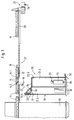
- den Einsatz einer erfindungsgemäß ausgestalteten Erfassungseinheit im Einsatz unter der Rollenbahn für den Abtransport gestreckter Werkstücke im Längsschnitt und
- Fig. 2
- ein hinsichtlich der Lichtquelle und zusätzlicher Lüftungsmaßnahmen abgewandeltes Ausführungsbeispiel für die Erfassungseinheit.
- Fig. 1
- the use of a detection unit designed according to the invention in use under the roller conveyor for the removal of elongated workpieces in longitudinal section and
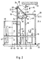
- Fig. 2
- an embodiment of the detection unit modified with regard to the light source and additional ventilation measures.
Bei den Werkstücken 11, deren an sich ebene Oberflächen 12 beispielsweise zu Klassifikationszwecken oder allgemein zur Qualitätskontrolle optronisch inspiziert werden sollen, kann es sich um in Transportrichtung 13 gestreckte Gußteile aus Kunststoff oder Metall handeln, die etwa Oberflächenfehler in Form von Lunkern und schlecht abgetrennten Angüssen aufweisen können. Bevorzugt handelt es sich aber um gehobelte Bretter und Balken, die nach Fehlstellen 14 insbesondere in Form von durchgehenden (Ast-)Löchern, größeren Vertiefungen und farblich gegenüber der Umgebung kontrastierenden Harz- oder Astflecken zu klassifizieren sind. Während Fehlstellen 14 mit starkem Helligkeitskontrast gegenüber ihrer Umgebung vergleichsweise zuverlässig von einem optronischen Sensor 15, vorzugsweise einer Zeilenkamera, erfaßt werden, wenn die Oberfläche 12 in Relativbewegung zwischen Werkstück 11 und Sensor 15 abgetastet wird, sind bloße Vertiefungen 14.1 ohne Farbkontrast zur Umgebung wesentlich schwieriger zu erfassen. Das gilt entsprechend für Löcher 14.2, die im Verhältnis zu ihrem Durchmesser bzw. zur Höhe des Werkstückes 11 so stark geneigt gegenüber der Oberfläche 12 verlaufen, daß sich aus geometrischen Gründen nicht die kontrastreiche Durchblick-Situation in Aufnahmerichtung ergibt.The
Deshalb ist die Bestrahlungsrichtung 17 um etwa 45° (gemessen entgegen der Transportrichtung 13) gegenüber der zu inspizierenden Oberfläche 12 und dementsprechend auch um etwa 45° gegenüber der quer zur Oberfläche 12 orientierten Aufnahmerichtung 16 geneigt. Das ergibt stets am Rande von Vertiefungen 14.1 und von Löchern 14.2 der Bestrahlungsrichtung 17 gegenüber und damit in Transportrichtung 13 einen kleinen Schattenwurf und somit einen problemlos erfaßbaren Fehlstellen-Kontrast auch ohne Durchblick Verhältnisse.Therefore, the direction of
Die Lichtquelle 18 für die Bestrahlungsrichtung 17 befindet sich im zweigeteilten Gehäuse 19 einer optoelektronischen Abtast- oder Erfassungseinheit 20, in der parallel zu einer Lichtkammer 21.3 eine nicht ganz so lange Sensorkammer 21.4 ausgebildet ist. Die Kammern 21 sind in Aufnahmerichtung 16 gestreckt. Der Sensor 15 ist der Blicköffnung 22.5 gegenüber im entlegenen Bereich der Sensorkammer 21.4 angeordnet, um einen möglichst großen Objektabstand zu erzielen, damit bei Einsatz eines Tele-Zwischenringes an der Optik 23 eines Zeilen-Sensors 15 die Oberfläche 12 über die gesamte Werkstück-Breite quer zur Transportrichtung 13 erfaßt werden kann. Der große Abstand erbringt auch optimale Abbildungsverhältnisse hinsichtlich Tiefenschärfe und weitgehende Unabhängigkeit von der an sich nach dem Cosinusgesetz schwankenden Intensität der Beleuchtungs-Rückstrahlung an der inspizierten Oberfläche 12.The
Entsprechend dem Winkel zwischen den streifenförmigen Aufnahme und Bestrahlungsrichtungen 16-17 geneigt gegenüber der Blicköffnung 12.5 ist der benachbarte Bereich der Lichtkammer 21.3 mit einer Lichtöffnung 22.6 abgeschlossen. Beide Öffnungen 22 sind mit am Gehäuse 19 eingefaßten, planparallelen Glasplatten 24 staubdicht verschlossen. Sie sind unter stumpfem Winkel zueinander orthogonal zu den Aufnahme- bzw. Bestrahlungsrichtungen 16, 17 orientiert, um in der Objektabbildung bzw. beim Lichtdurchtritt Streuungen und Reflexionen an den Glasplatten 24 zu vermeiden, die sich sonst den auszuwertenden Oberflächenmustern störend überlagern könnten.Corresponding to the angle between the strip-shaped receptacle and irradiation directions 16-17 inclined with respect to the viewing opening 12.5, the adjacent area of the light chamber 21.3 is closed off with a light opening 22.6. Both openings 22 are closed in a dust-tight manner by
Der Sensor 15 ist über ein Interface 25 an eine Auswerteschaltung etwa der Art angeschlossen, wie sie in der Publikation "Real time surface grading of profiled wooden boards" von W. Pölzleitner und G. Schwingshakl in INDUSTRIAL METROLOGY Vol. 2, Nos. 3-4, 1992, pp. 283 - 298, insbesondere zur Klassifikation gehobelter Profilbretter ausführlich beschrieben ist. Eine solche Auswerteschaltung kann eine Steuerungsinformation 26 an einen Sorter 27 liefern, bei dem es sich wie skizziert einfach um einen einstellbaren Anschlag 28 vor einem Querförderer 29 für Abtransport der inspizierten Werkstücke 11 oder auch um eine vollautomatische Sortierweiche handeln kann. Das vergleichsweise schwere Netzteil 30 für die Betriebsversorgung des Sensors 15 samt Interface 25 und insbesondere für die Leistungsversorgung der Lichtquelle 18 ist bei Auslegung der Erfassungseinheit 20 als Boden-Stand-Gerät aus Stabilitätsgründen vorzugsweise der Lichtöffnung 22.6 gegenüber im unteren Bereich der Lichtkammer 21.3 angeordnet.The
Beim Netzteil 30 handelt es sich insbesondere um einen Frequenzwandler, wenn die Lichtquelle 18 in einem wannenförmig-hohlzylindrischen Reflektor 31 mit parallel zur Reflektorachse (und somit entsprechend dem schmalen an der Oberfläche 12 von einer Zeilenkamera aufgenommenen Streifen quer zur Darstellebene der Fig. 1) sich erstreckenden Kaltlicht-Leuchtstoffröhren 32 bestückt ist. Die werden zur Vermeidung optischer Schwebungserscheinungen mit einer Hochfrequenz in der Größenordnung einiger zehn KHz betrieben. Solche Edelgas-Leuchtstoffröhren 32 zeichnen sich durch lange Lebensdauer und geringe Verlustwärme aus, liefern allerdings für manche Anforderungen an die Oberflächeninspektion (zumal unter Berücksichtigung der Maserungsmuster bei gehobeltem Holz) nicht das ideale Strahlungsspektrum und die ideale Strahlengeometrie.The
Auch mit einer Steigerung der elektrischen Leistung durch eine größere Anzahl von Edelgas-Leuchtstoffröhren 32 läßt sich keine wesentliche Steigerung des Wirkungsgrades der zeilenförmigen Ausleuchtung an der zu inspizierenden Oberfläche 12 erzielen, weil die Leuchtdichte solcher Leuchtstoffröhren 32 an sich schon gering ist und eine derartige Anordnung längs eines halben hohlzylindrischen Reflektors 31 nicht die notwendigen geometrischen Verhältnisse für eine eindeutige Zeilen-Fokussierung erbringt. Deshalb ist die Ausstattung der Lichtquelle 18 durch Halogenstrahler 33 mit integriertem Reflektor zweckmäßiger. Wenn diese aus dem Netzteil 30 mit Gleichspannung betrieben werden, können störende optische Schwebungserscheinungen an der inspizierten Oberfläche 12 nicht auftreten. Für die Zeileninspektion kann es sich bei den Halogenstrahlern 33 gemäß Fig. 2 um eine Zeile von nebeneinander angeordneten kleinen Niederspannungs-Lampen oder um einer gegenüber ihrem Reflektor 31 einstellbare röhrenförmige Hochspannungslampe handeln, wenn nicht bei beliebiger Lampenanordnung eine Lichtquerschnittsanpassung mit Lichtleitern vorgesehen ist. Für die Gleichstromspeisung genügt es, im Netzteil 30 eine dreiphasige Wechselspannung gleichzurichten.Even with an increase in the electrical power due to a larger number of noble gas fluorescent tubes 32, no significant increase in the efficiency of the line-shaped illumination on the
In Hinblick auf ihre enorme Hitzeabstrahlung ist eine Zeile von Halogenstrahlern 33 vorzugsweise nicht unmittelbar parallel hinter der Glasplatte 24 der Lichtöffnung 22.6 angeordnet, sondern längs des resultierenden Strahlenweges erheblich dagegen versetzt. Um dennoch den schlanken Querschnitt der Lichtkammer 21.3 im Interesse kompakten Aufbaues der Erfassungseinheit 20 beibehalten zu können, sind die Halogenstrahler 33 abstrahlseitig etwa parallel zur Lichtöffnung 22.6 orientiert, mit Umlenkung ihrer Strahlung an einem Spiegel 34 für senkrechten Durchtritt der Bestrahlungsrichtung 17 durch die Lichtöffnungs-Glasplatte 24. Dadurch ist ein sehr großer Luftraum zwischen den Halogenstrahlern 33 und der Glasplatte 24 vor der Lichtöffnung 22.6 und damit die wünschenswert große Wärmekapazität für die Halogenstrahler-Verlustwärme erzielt.In view of their enormous heat radiation, a row of
Ein Gebläse 35 kann durch Zwangszirkulation einem Wärmestau hinter der Glasplatte 24 entgegenwirken. Jedoch verbieten Explosionsschutz-Sicherheitsanforderungen etwa in der holzverarbeitenden Industrie einen Luftaustausch mit der Umgebung außerhalb des hermetisch gekapselten Gehäuses 19. Deshalb ist das Gebläse 35 in der Trennwand 39 zwischen Lichtkammer 21.3 und Sensorkammer 21.4 angeordnet, und zwar möglichst weit oben im Gehäuse 19, also möglichst dicht hinter den Scheiben 24 und somit dicht bei der Wärme-und Lichtquelle 18. Für eine Umluft-Zirkulation 40 weist die Trennwand 39 dem Gebläse 35 gegenüber, also im unteren Bereich des Gehäuses 19, eine Aussparung oder sonstige Öffnungen 41 auf. Die Strömungsrichtung der Umluft 40 ist vorzugsweise so, daß die warme Luft aus der Umgebung der Lichtquelle 18 nicht direkt auf die Kamera (Sensor 15 mit Optik 23) geblasen wird, sondern daß an dem Sensor 15 erst die zuvor der Konvektionsrichtung entgegen durch die Lichtkammer 21.3 abwärtsgedrückte Umluft 40 vorbeistreicht, nachdem sie auf diesem Wege bereits eine gewisse Abkühlung erfahren hat. Im Interesse möglichst guter Wärmeabfuhr aus dem unteren Bereich der Lichtkammer 21.3 ist ein Teil von deren Außenwand 42 als Wärmetauscher 43 mit einer massereichen Platte 44 und etwa rechtwinklig davon abstehenden, parallel zur Längserstreckung der Lichtkammer 21.3 verlaufenden Rippen 45 ausgebildet, oder ein solcher Wärmetauscher 43 ist in eine Aussparung der Außenwand 42 eingefügt. So streicht die durch das Gebläse 35 in der Lichtkammer 21.3 abwärtsgedrückte Umluft-Strömung 40 zur Wärmeabgabe in Längsrichtung durch die Rippen 45 hindurch, ehe sie durch die Öffnungen 41 in die Sensorkammer 21.4 übertritt und dort wieder als abgekühlte Luftströmung 40 hochgedrückt bzw. hochgesaugt wird. Zur wirkungsvolleren Abgabe der aufgenommenen Wärmeenergie an die Umluft außerhalb des hermetisch geschlossenen Gehäuses 19 ist die Wärmetauscher-Platte 44 vorzugsweise auch außerhalb des Gehäuses 19 mit Rippen 45 ausgestattet. Zur Steigerung der Konvektionswärmeübertragung kann diesen ein Ventilationskasten 46 mit einem Ventilator 47 aufgesetzt sein, der zur gesteigerten Wärmeabfuhr eine Zwangsströmung durch die äußeren Rippen 45 hervorruft. Zur Abfuhr der Lichtquellen-Wärme aus dem hermetisch geschlossenen Gehäuse 19 kann aber auch ein Luft-Wasser-Wärmetauscher vorgesehen sein, der dann keines externen Ventilators 47 mehr bedarf; oder als Wärmetauscher 43 wird in die Außenwand 42 ein Klimagerät eingesetzt, dessen Verdampfer im Umluftstrom 40 durch die Lichtkammer 21.3 liegt, während Verdichter und Kondensator des Klimagerätes außerhalb des Gehäuses 19 angeordnet sind. Wenn innerhalb der Lichtöffnung 22.6 eine Anzahl von extern mit Druckluft-Stößen beaufschlagten Düsen 48 in die Lichtkammer 21.3 hineinragen, mittels derer zumindest die Licht-Scheibe 24 (ggf. aber zusätzlich auch die Sensor-Scheibe 24) von aus der Umluftströmung 40 resultierenden Ablagerungen freigeblasen wird, dann wird dadurch die Luftverwirbelung und somit die Wärmeabfuhr noch zusätzlich gefördert.A
Eine wesentliche Steigerung des Wirkungsgrades infolge besserer bspw. linienförmiger Fokussierung der Lichtstrahlung auf der Oberfläche 12 ist noch dadurch erzielbar, daß die Halogenlampen-Abstrahlung mittels einer in diesem Beispiel halbzylindrischen Linse 38 zusätzlich fokussiert wird. Für gleiche Ausleuchtung kann dann eine Lichtquelle 18 niedrigerer elektrischer Leistung und damit auch geringerer Verlustwärme eingesetzt werden. Die Linse 38 kann an sich innerhalb der Lichtkammer 21.3 im Strahlenweg zwischen Lichtquelle 18 und Glasplatte 24 angeordnet oder gar mit dem Spiegel 34 kombiniert sein, würde dort allerdings das aus Gründen der Wärmekapazität wünschenswerte Luftvolumen reduzieren. Deshalb kann auch in Betracht gezogen sein, wie in Fig. 2 berücksichtigt, die Linse 38 auf der Glasplatte 24 vor der Lichtkammer 21.3 anzuordnen oder diese Glasplatte direkt durch die Linse 38 zu ersetzen.A significant increase in efficiency as a result of better, for example, linear focusing of the light radiation on the
Die kompakte, in sich voll funktionstüchtige Erfassungseinheit 20 kann leicht in eine Fertigungsanlage integriert werden, etwa am Ausgang einer Hobelmaschine 36 unter der Rollenbahn 37 zum Abtransport von Werkstücken 11 in Form von Profilbrettern, deren gehobelte Unterseite zur Güteklassifizierung zu inspizieren ist. Dabei kommt das völlig geschlossene Gehäuse 19 Anforderungen an Einsatz in explosionsgefährdeter Umgebung entgegen. Da eine Justage der Aufnahme- und Betrachtungsrichtungen 16, 17 schon beim Einbau des Sensors 15 und der Lichtquelle 18 erfolgt, werden bei der Integration dieser in sich abgeglichenen Erfassungseinheit 20 in den Fabrikationsgang keine aufwendigen weiteren Justagevorgänge mehr erforderlich.The compact, fully
Claims (10)
dadurch gekennzeichnet,
daß sich in einem Gehäuse (19) parallel zu einer Sensorkammer (21.4) eine Lichtkammer (21.3) erstreckt, deren quer zur Bestrahlungsrichtung (17) orientierte Lichtöffnung (22.6) stumpfwinklig geneigt ist gegenüber der quer zur Aufnahmerichtung (16) orientierten Blicköffnung (22.5) der Sensorkammer (21.4).Detection unit (20) for the optronic inspection of a surface (12), in particular for classifying rapidly moving workpieces (11), by means of a sensor (15) directed transversely to the direction of movement on the surface (12),
characterized,
that a light chamber (21.3) extends in a housing (19) parallel to a sensor chamber (21.4), the light opening (22.6) oriented transversely to the irradiation direction (17) is inclined at an obtuse angle to the viewing opening (22.5) oriented transversely to the recording direction (16) the sensor chamber (21.4).
dadurch gekennzeichnet,
daß als Sensor (15) in der Sensorkammer (22.4) eine Zeilenkamera mit Tele-Zwischenring für ihre Optik (23) in möglichst großem Abstand von der Blicköffnung (22.5) angeordnet ist.Device according to claim 1,
characterized,
that as a sensor (15) in the sensor chamber (22.4) a line camera with a telephoto intermediate ring for its optics (23) is arranged as far as possible from the viewing opening (22.5).
dadurch gekennzeichnet,
daß in der Lichtkammer (21.3) hinter der von einer Glasplatte (24) hermetisch verschlossenen Lichtöffnung (22.6) als Lichtquelle (18) eine Anzahl von Leuchtstoffröhren (32) auf der konkaven Seite eines halbzylindrischen Hohlspiegels als gestrecktem Reflektor (31) angeordnet ist, die an eine Hochfrequenz-Speisung angeschlossen sind.Device according to claim 1 or 2,
characterized,
that in the light chamber (21.3) behind the light opening (22.6) hermetically sealed by a glass plate (24) as the light source (18) a number of fluorescent tubes (32) is arranged on the concave side of a semi-cylindrical concave mirror as a stretched reflector (31) which are connected to a high-frequency supply.
dadurch gekennzeichnet,
daß in der Lichtkammer (21.3) hinter einer deren Lichtöffnung (22.6) hermetisch abschließenden Glasplatte (24) als Lichtquelle (18) Halogenstrahler (33) in Form von wenigstens zwei nebeneinander angeordneten Niederspannungs-Lampen angeordnet sind, die an eine Gleichspannungs-Speisung angeschlossen sind.Device according to claim 1 or 2,
characterized,
that in the light chamber (21.3) behind a light opening (22.6) hermetically sealing glass plate (24) as light source (18) halogen lamps (33) in the form of at least two juxtaposed low-voltage lamps are arranged, which are connected to a DC voltage supply .
dadurch gekennzeichnet,
daß in der Lichtkammer (21.3) hinter einer deren Lichtöffnung (22.6) abschließenden Glasplatte (24) als Lichtquelle (18) wenigstens eine Hochleistungs-Halogenröhre angeordnet ist, die gegenüber ihrem hohlzylindrischen Reflektor einstellbar und über einen Gleichrichter aus einem dreiphasigen Wechselspannungsnetz gespeist ist.Device according to claim 1 or 2,
characterized,
that at least one high-performance halogen tube is arranged in the light chamber (21.3) behind a glass plate (24) closing its light opening (22.6) as a light source (18), which is adjustable relative to its hollow cylindrical reflector and fed from a three-phase AC voltage network via a rectifier.
dadurch gekennzeichnet,
daß wenigstens eine Strahl-Umlenkeinrichtung in der Lichtkammer (21.3) zwischen dem Halogenstrahler (33) und der Lichtöffnung (22.6) angeordnet ist.Device according to claim 4 or 5,
characterized,
that at least one beam deflection device is arranged in the light chamber (21.3) between the halogen lamp (33) and the light opening (22.6).
dadurch gekennzeichnet,
daß im Strahlengang des Halogenstrahles (33) eine Linse (38) angeordnet ist.Device according to claim 4 or 5,
characterized,
that a lens (38) is arranged in the beam path of the halogen beam (33).
dadurch gekennzeichnet,
daß sie ein explosionssicher ausgelegtes Gehäuse (19) aufweist.Device according to one of the preceding claims,
characterized,
that it has an explosion-proof housing (19).
Applications Claiming Priority (2)
| Application Number | Priority Date | Filing Date | Title |
|---|---|---|---|
| DE9310554U DE9310554U1 (en) | 1993-07-15 | 1993-07-15 | Registration unit for the optronic surface inspection |
| DE9310554U | 1993-07-15 |
Publications (1)
| Publication Number | Publication Date |
|---|---|
| EP0634648A1 true EP0634648A1 (en) | 1995-01-18 |
Family
ID=6895612
Family Applications (1)
| Application Number | Title | Priority Date | Filing Date |
|---|---|---|---|
| EP94104585A Withdrawn EP0634648A1 (en) | 1993-07-15 | 1994-03-23 | Device for the optoelectric surface inspection |
Country Status (2)
| Country | Link |
|---|---|
| EP (1) | EP0634648A1 (en) |
| DE (1) | DE9310554U1 (en) |
Cited By (8)
| Publication number | Priority date | Publication date | Assignee | Title |
|---|---|---|---|---|
| DE19534716A1 (en) * | 1995-09-19 | 1997-03-20 | Autronic Bildverarbeitung | Device for detecting defects on a smooth surface |
| DE19604076A1 (en) * | 1996-02-05 | 1997-08-07 | F & O Electronic Systems | Device for inspecting the surface of wood for the determination of surface features and method therefor |
| DE19604075A1 (en) * | 1996-02-05 | 1997-08-14 | F & O Electronic Systems | Device for inspecting the surface of wood for the determination of surface features and method therefor |
| DE19716468A1 (en) * | 1997-04-21 | 1998-10-29 | Autronic Bildverarbeitung | Unit for surface inspection of wood specimen esp. for quality control-classification |
| DE19716803A1 (en) * | 1997-04-22 | 1998-11-05 | Autronic Bildverarbeitung | Arrangement for optronic inspection of surface of workpiece transported longitudinally |
| DE19827270A1 (en) * | 1998-06-19 | 1999-12-23 | Autronic Bildverarbeitung | Device for detection of surface irregularities on a test sample such as a piece of wood or fabric by illumination of the surface and detection of the reflections |
| US10619921B2 (en) | 2018-01-29 | 2020-04-14 | Norev Dpk, Llc | Dual path kiln and method of operating a dual path kiln to continuously dry lumber |
| CN113567468A (en) * | 2020-04-28 | 2021-10-29 | 宝山钢铁股份有限公司 | Tube and bar surface self-adaptive imaging system and method suitable for V-shaped roller way conveying |
Families Citing this family (2)
| Publication number | Priority date | Publication date | Assignee | Title |
|---|---|---|---|---|
| DE19840061A1 (en) * | 1998-09-03 | 2000-03-09 | Autronic Bildverarbeitung | Method of driving sorting or trimming devices according to classification of elongated wooden product defects involves converting defect location information into control classifications |
| DE102019106218B3 (en) * | 2019-03-12 | 2020-06-18 | Pfeifer Holz Gmbh | Method and device for classifying wood products |
Citations (4)
| Publication number | Priority date | Publication date | Assignee | Title |
|---|---|---|---|---|
| GB894570A (en) * | 1959-07-15 | 1962-04-26 | British Iron Steel Research | Improvements in or relating to the detection of surface abnormalities |
| DE3248782A1 (en) * | 1982-12-31 | 1984-07-05 | Feldmühle AG, 4000 Düsseldorf | Method and device for testing surfaces |
| DE9104596U1 (en) * | 1991-04-16 | 1991-07-04 | Roehm Gmbh, 6100 Darmstadt, De | |
| DE9202306U1 (en) * | 1992-02-22 | 1993-06-17 | Autronic Gesellschaft Fuer Bildverarbeitung Und Systeme Mbh, 7500 Karlsruhe, De |
-
1993
- 1993-07-15 DE DE9310554U patent/DE9310554U1/en not_active Expired - Lifetime
-
1994
- 1994-03-23 EP EP94104585A patent/EP0634648A1/en not_active Withdrawn
Patent Citations (4)
| Publication number | Priority date | Publication date | Assignee | Title |
|---|---|---|---|---|
| GB894570A (en) * | 1959-07-15 | 1962-04-26 | British Iron Steel Research | Improvements in or relating to the detection of surface abnormalities |
| DE3248782A1 (en) * | 1982-12-31 | 1984-07-05 | Feldmühle AG, 4000 Düsseldorf | Method and device for testing surfaces |
| DE9104596U1 (en) * | 1991-04-16 | 1991-07-04 | Roehm Gmbh, 6100 Darmstadt, De | |
| DE9202306U1 (en) * | 1992-02-22 | 1993-06-17 | Autronic Gesellschaft Fuer Bildverarbeitung Und Systeme Mbh, 7500 Karlsruhe, De |
Cited By (16)
| Publication number | Priority date | Publication date | Assignee | Title |
|---|---|---|---|---|
| EP0764845A2 (en) * | 1995-09-19 | 1997-03-26 | AUTRONIC Gesellschaft für Bildverarbeitung und Systeme mbH | Apparatus for detecting defective portion on a smooth surface |
| EP0764845A3 (en) * | 1995-09-19 | 1997-09-17 | Autronic Bildverarbeitung | Apparatus for detecting defective portion on a smooth surface |
| DE19534716A1 (en) * | 1995-09-19 | 1997-03-20 | Autronic Bildverarbeitung | Device for detecting defects on a smooth surface |
| DE19534716C2 (en) * | 1995-09-19 | 1999-06-17 | Autronic Bildverarbeitung | Device for detecting defects on a smooth surface |
| DE19604076A1 (en) * | 1996-02-05 | 1997-08-07 | F & O Electronic Systems | Device for inspecting the surface of wood for the determination of surface features and method therefor |
| DE19604075A1 (en) * | 1996-02-05 | 1997-08-14 | F & O Electronic Systems | Device for inspecting the surface of wood for the determination of surface features and method therefor |
| DE19604076C2 (en) * | 1996-02-05 | 1998-02-19 | F & O Electronic Systems | Device for inspecting the surface of wood for the determination of surface features and method therefor |
| DE19604075C2 (en) * | 1996-02-05 | 1998-02-19 | F & O Electronic Systems | Device for inspecting the surface of wood for the determination of surface features and method therefor |
| DE19716468C2 (en) * | 1997-04-21 | 1999-07-08 | Autronic Bildverarbeitung | Device for surface inspection, especially of wood |
| DE19716468A1 (en) * | 1997-04-21 | 1998-10-29 | Autronic Bildverarbeitung | Unit for surface inspection of wood specimen esp. for quality control-classification |
| DE19716803A1 (en) * | 1997-04-22 | 1998-11-05 | Autronic Bildverarbeitung | Arrangement for optronic inspection of surface of workpiece transported longitudinally |
| DE19716803C2 (en) * | 1997-04-22 | 2000-10-26 | Autronic Bildverarbeitung | Device for the optronic inspection of the surface of a workpiece transported in the longitudinal direction |
| DE19827270A1 (en) * | 1998-06-19 | 1999-12-23 | Autronic Bildverarbeitung | Device for detection of surface irregularities on a test sample such as a piece of wood or fabric by illumination of the surface and detection of the reflections |
| US10619921B2 (en) | 2018-01-29 | 2020-04-14 | Norev Dpk, Llc | Dual path kiln and method of operating a dual path kiln to continuously dry lumber |
| CN113567468A (en) * | 2020-04-28 | 2021-10-29 | 宝山钢铁股份有限公司 | Tube and bar surface self-adaptive imaging system and method suitable for V-shaped roller way conveying |
| CN113567468B (en) * | 2020-04-28 | 2023-11-14 | 宝山钢铁股份有限公司 | Pipe rod surface self-adaptive imaging system and method suitable for V-shaped roller way conveying |
Also Published As
| Publication number | Publication date |
|---|---|
| DE9310554U1 (en) | 1994-11-17 |
Similar Documents
| Publication | Publication Date | Title |
|---|---|---|
| DE19504111C2 (en) | Image reading device | |
| EP0930600B1 (en) | Optical element comprising LED and two lenses for the generation of pointlike light sources for traffic signs and display panels | |
| EP1830178B1 (en) | Device for emitting linear light | |
| DE3130381C2 (en) | ||
| EP0634648A1 (en) | Device for the optoelectric surface inspection | |
| EP2391884A1 (en) | Device for optically inspecting an at least partially reflecting surface of an item | |
| DE102006004003A1 (en) | Infrared gas detector for detecting gas concentration based on light absorption properties using infrared light source and infrared sensor | |
| DE60110764T2 (en) | LIGHTING SYSTEM FOR USE IN A PICTURE RECORDING SYSTEM FOR MOVING OBJECTS | |
| DE112017001072B4 (en) | Light guide, detector with light guide and charged particle beam device | |
| EP0920616B1 (en) | Device for visually inspecting the surface condition of large-dimension surfaces to be matched | |
| EP2793066A2 (en) | Ring illumination device for a microscope lens and microscope lens | |
| AT410711B (en) | SIGNAL OPERATOR OPTICS WITH LED ROWS | |
| EP0180800B1 (en) | Sun simulator | |
| DE4426968C2 (en) | Optical examination device | |
| EP0386795A2 (en) | Lightstand | |
| DE102004035786B4 (en) | Inline inspection systems | |
| DE3938938C2 (en) | Episcope | |
| DE60038293T2 (en) | PORTABLE LIGHT SOURCE | |
| DE102006022351A1 (en) | Device for room temperature regulation and room lighting | |
| DE1622978B1 (en) | OPTICAL PROJECTION DEVICE | |
| DE19603025A1 (en) | Light generator for feeding into optical fibers | |
| EP0947827A1 (en) | Apparatus for inspecting surfaces of bodies lying in different planes | |
| DE102015101252B4 (en) | Illumination device, optical analysis system and method for scanning a surface | |
| WO2001016584A1 (en) | System for inspecting matt, flat and/or slightly curved surfaces | |
| DE19957811A1 (en) | Lighting unit has rectangular box format with reflective top and side walls, with lighting tubes installed in end compartments, together with clear prism plates |
Legal Events
| Date | Code | Title | Description |
|---|---|---|---|
| PUAI | Public reference made under article 153(3) epc to a published international application that has entered the european phase |
Free format text: ORIGINAL CODE: 0009012 |
|
| AK | Designated contracting states |
Kind code of ref document: A1 Designated state(s): AT CH DE DK FR GB IT LI SE |
|
| 17P | Request for examination filed |
Effective date: 19941129 |
|
| 17Q | First examination report despatched |
Effective date: 19961119 |
|
| 19U | Interruption of proceedings before grant |
Effective date: 19991101 |
|
| 19W | Proceedings resumed before grant after interruption of proceedings |
Effective date: 20010409 |
|
| RAP1 | Party data changed (applicant data changed or rights of an application transferred) |
Owner name: KMS VISION SYSTEMS GMBH |
|
| STAA | Information on the status of an ep patent application or granted ep patent |
Free format text: STATUS: THE APPLICATION IS DEEMED TO BE WITHDRAWN |
|
| 18D | Application deemed to be withdrawn |
Effective date: 20011101 |